


880

ADDENDUM SHEET
For Model 880 MAN-027 (December 2005 Revision)
This following provides information on the Model 880 OMEGA radiographic exposure
device and identifies differences for this device not currently addressed in MAN-027.
The Model 880 OMEGA general description is identical to all other Model 880 source
projectors except for the following:
1. The Model 880 OMEGA is identified by a Safety Orange colored optional
jacket.
2. The maximum package weight is as follows:
•With Jacket: 33 lbs (15 kg)
•Without Jacket: 28 lbs (13 kg)
3. The maximum depleted uranium shield weight is 17 lbs (7.7 kg)
4. The maximum radioscope capacity is as follows:
•15 Ci (0.55 TBq) Ir-192
•80 Ci (2.96 TBq) Se-75
•30 Ci (1.1 1 TBq) Yb-169
5. The Model 880 OMEGA is evaluated as a USDOT T ype A T ransport Container .
The Model 880 OMEGA is NOT approved as a T ype B transport package.
Labeling for this device reflects the T ype A information for the p ackage
instead of the the T ype B information referenced for the other versions of the
Model 880 described in MAN-027.
Contact QSA Global, Inc. if additional information is required.
This sheet must be included with all copies of the above referenced manual.
Addendum Sheet issued April 2006
DANGER - IMPORTANT WARNINGS
i
The system must be operated only by trained and qualified radiographers who have
read and understand this Operating Manual or by trained assistants working under their
direct supervision.
WARNING
The use of this radiographic exposure device by unqualified personnel or when safety
procedures are not fully met, could result in life-threatening dangers.
Gamma radiography systems emit high levels of highly penetrating radiation during use.
An unshielded radiation source at close range can cause injury, sickness or death to anyone
who is exposed to it even for a short period of time.
A radiation source (or an unshielded source assembly) must NOT be touched by the hands
under any circumstances.
Since gamma radiation cannot be detected by the human senses, strict operating and
emergency procedures must be followed. The proper use of calibrated and operable survey
meters must be employed to avoid potentially dangerous levels of radiation exposure.
Proper dosimetry including film badges or thermoluminescent dosimeters,
direct reading pocket dosimeters and audible alarm ratemeters must be worn during all
radiographic operations.
During use of this radiography system, never assume the position of the radiation source.
Always conduct a thorough confirmatory survey using a calibrated and operable survey
meter to verify the location of the radiation source. Be reminded that a multitude of
overexposure incidents which include injuries are directly attributed to a failure of the
radiographer to perform or supervise an adequate confirmatory survey.
It is very important and required by national regulations to prevent access by unauthorized
persons to radiographic equipment and to the area where radiography is performed.
Take advantage of the three basic radiation protection methods to minimize
radiation exposure:
TIME
Spend less time near the radiation source.
DISTANCE
Increase your distance in a direction away from the radiation source.
SHIELDING
The use of effective shielding between you and the radiation source.
Do not perform any unauthorized modifications to the radiographic exposure device or
components of the radiography system.
It is important that trained and qualified radiographers perform or supervise a daily safety
inspection of the radiography system for obvious defects prior to operation of the system.
Do not use any components that are not approved for use with the radiography system or
after-market components that may compromise the safety designed into the system.
CONTENTS
ii
1 TECHNICAL SPECIFICATIONS 1.1 - 1.6
2 OPERATING INSTRUCTIONS 2.1 - 2.11
3 DAILY INSPECTION INSTRUCTIONS 3.1 - 3.9
4 MAINTENANCE INSTRUCTIONS 4.1 - 4.16
5 SAMPLE TRANSPORTATION INSTRUCTIONS 5.1 - 5.12
6 DEFINITIONS AND TERMS 6.1 - 6.3
7 EMERGENCIES AND PERSONNEL SAFETY 7.1 - 7.2
8 INSTRUCTIONS FOR DISPOSAL 8.1
iii
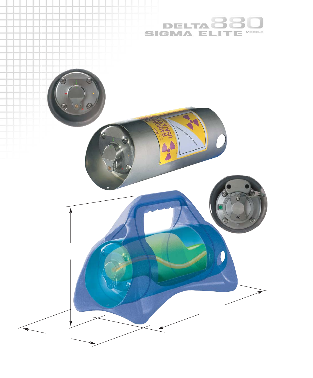
13.3in
338mm
7.5in
191mm
FRONT VIEW
Outlet port
Guide tube connector
880 Delta 150Ci (5.55TBq)
Maximum package weight
With jacket 52lb (24kg)
Without jacket 46lb (21kg)
880 Sigma 130Ci (4.81TBq)
Maximum package weight
With jacket 52lb (24kg)
Without jacket 46lb (21kg)
880 Elite 50Ci (1.85TBq)
Maximum package weight
With jacket 42lb (19kg)
Without jacket 37lb (17kg)
REAR VIEW
Locking mechanism
Remote control connector
9in
229mm
TECHNICAL SPECIFICATIONS
1.1
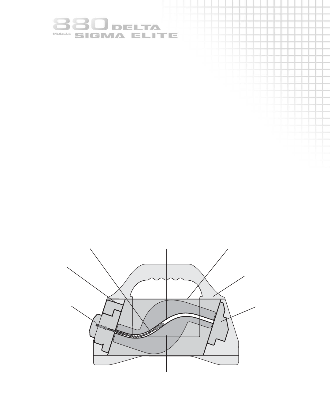
Titanium ‘S’ tubeSource assembly
Plunger lock
Locking mechanism
Remote
control
connector
Outlet port
Guide tube
connector
Depleted Uranium shield
Welded shield container
Protective
plastic jacket with
carrying handle
Exposure device description
The Model 880 Delta, Model 880 Sigma and Model 880 Elite are physically small,
lightweight, portable industrial radiographic exposure devices. The ‘S’ tube design exposure
device consists of a cast depleted Uranium (DU) shield contained and secured within a
300 series stainless steel tube with stainless steel discs welded at each end to form a cylinder
shaped housing. Both discs are recessed into the stainless steel tube to provide protection
for the locking mechanism at the rear side and the outlet port at the front side.
The welded tubular housing is oriented horizontally to provide easy access to the locking
mechanism and source assembly connector and to provide easy access to the outlet port for
connection of projection sheaths. The internal void space of the welded housing is filled
with polyurethane foam to prevent the ingress of water or foreign material but is open to
atmospheric pressure. The stainless steel housing containing the DU shield, locking
mechanism, outlet port, protective covers and required labels comprise the radioactive
material transport package.
A plastic jacket surrounds the welded housing and serves as a protective barrier for the labels
and provides the means for carrying and placement during use as a radiographic exposure
device. The Model 880 Delta is identified by a yellow colored jacket, the Model 880 Sigma is
identified by a black colored jacket and the Model 880 Elite is identified by a blue colored
jacket. The plastic jacket incorporates a carrying handle and a base that is used during
radiographic operations but is not required for transportation purposes. The plastic jacket may
be removed for certain applications such as when the exposure device is securely mounted
to a pipe-crawler locomotive or a pipe-liner sled.
The Model 880 Delta, Sigma and Elite exposure devices are designed, tested, manufactured to
meet the requirements of ANSI N432-1980, ISO 3999-1:2000(E), IAEA-ST1, IAEA TS-R-1 (1996),
USNRC 10CFR34, 10CFR71 and 49CFR173 requirements. Additionally, the exposure device is
designed, manufactured and serviced under a ISO 9001 QA program and a USNRC 10CFR71,
Subpart H QA program. The QA program also includes the reporting requirements of
USNRC 10CFR21 for suppliers of source and byproduct materials.
TECHNICAL SPECIFICATIONS
1.2
Applications
The Model 880 devices are used for industrial applications of gamma radiography, mainly
with Iridium-192, to inspect materials and structures in the density range of approximately
2.71g/cm
3
through 8.53g/cm3. The Model 880 devices also accommodate low energy
isotopes to permit radiography of materials and structures of thin sections of steel and lowdensity alloys. The Model 880 exposure devices are also designed for use with low activity
sources with high photon energies that are used for mass absorption (gamma scanning)
studies of high-density materials up to 18.7g/cm
3
.
Standard source assembly
Metallic Iridium-192 discs and pellets are doubly encapsulated in welded stainless steel or
titanium capsules. The sealed sources are designed and tested to achieve an ISO/ANSI minimum
classification of 77C43515 to comply with the IAEA and USDOT requirements for
‘Special Form’ radioactive material. The ISO/ANSI classification 77C43515 stated in this manual
refers to the complete source assembly . The inner capsule (excluding X.540N) has been tested to
ISO/ANSI 77C64515 and therefore meets all the requirements of the IAEA T ransport Regulations.
The sealed source is swaged to one end of a source holder consisting of a short flexible steel
cable which has the female half of a connector at the other end, used for coupling to a
control cable connector. The source assembly also has a stainless steel stop-ball swaged onto it
slightly forward from the source holder's connector. The purpose of the stop-ball is to provide
mechanical positioning of the source assembly within the exposure device's shielding and to
provide a means of securing the source assembly in the exposure device's locking mechanism.
Model 880 Delta authorized contents
Isotope Assembly Gamma Half life Approximate Device/source
model energy steel working maximum
number range thickness capacity
Ytterbium-169 918 8-308keV 32 days 2-20mm 20Ci 0.74TBq
Selenium-75 A424-25W 66-401keV 120 days 3-29mm 80Ci 3.00TBq
Iridium-192 A424-9 206-612keV 74 days 12-63mm 150Ci 5.55TBq
Cobalt-60 A424-19 1.17-1.33MeV 5.27 years 50-150mm 65mCi 2.40GBq
Model 880 Sigma authorized contents
Isotope Assembly Gamma Half life Approximate Device/source
model energy steel working maximum
number range thickness capacity
Ytterbium-169 918 8-308keV 32 days 2-20mm 20Ci 0.74TBq
Selenium-75 A424-25W 66-401keV 120 days 3-29mm 80Ci 3.00TBq
Iridium-192 A424-9 206-612keV 74 days 12-63mm 130Ci 4.81TBq
Cobalt-60 A424-19 1.17-1.33MeV 5.27 years 50-150mm 25mCi 925MBq
Model 880 Elite authorized contents
Isotope Assembly Gamma Half life Approximate Device/source
model energy steel working maximum
number range thickness capacity
Ytterbium-169 918 8-308keV 32 days 2-20mm 20Ci 0.74TBq
Selenium-75 A424-25W 66-401keV 120 days 3-29mm 80Ci 3.00TBq
Iridium-192 A424-9 206-612keV 74 days 12-63mm 50Ci 1.85TBq
Cobalt-60 A424-19 1.17-1.33MeV 5.27 years 50-150mm 25mCi 925MBq
TECHNICAL SPECIFICATIONS
Source output
At 1m per Ci (37GBq) At 1ft per Ci (37GBq)
Ytterbium-169 0.125R/hr 1.25mSv/hr 1.3R/hr/Ci 13.0mSv/hr
Selenium-75 0.203R/hr 2.03mSv/hr 2.2R/hr/Ci 22.0mSv/hr
Iridium-192 0.48R/hr 4.80mSv/hr 5.2R/hr/Ci 52.0mSv/hr
Cobalt-60 1.30R/hr 13.0mSv/hr 14.0R/hr/Ci 140mSv/hr
Selected attenuation data
Material Approximate Approximate half value thickness
Concrete 2.35g/cm
Aluminum 2.65g/cm
Steel 7.80g/cm
Lead 11.34g/cm
Tungsten 17.80g/cm
DU 18.70g/cm
Operating distance
The distance between the remote control and the exposure head is determined by summing
the length of the remote control conduits plus the total length of source guide tubes used,
and normally should not exceed 47ft (14.2m).
Standard remote controls:
25ft (7.6m), 35ft (10.7m), 50ft (15m).
Standard source guide tubes (projection sheaths):
7ft (2.1m) set of three source guide tubes: 21ft total (6.3m).
NOTE
The total length of source guide tubes utilized must be shorter in length than the remote
controls to ensure the source assembly will project into the working position.
e.g. When using 25ft (7.6m) remote controls, a maximum of three
7ft (2.1m) source guide tubes can be used with a combined length of 21ft (6.4m).
Conversely, when using 35ft (10.7m) remote controls, a maximum of four
7ft (2.1m) source guide tubes can be utilized.
When using 50ft (15m) remote controls, a maximum of six 7ft (2.1m) source guide
tubes can be utilized. This limitation is due to the weight and friction of remote control
cable length.
material inches(mm)
density Ytterbium-169 Selenium-75 Iridium-192 Cobalt-60
3
1.140 (29.0) 1.180 (30.0) 1.700 (43.2) 2.400 (61.0)
3
3
3
3
3
– 1.100 (27.0) – –
0.170 (4.3) 0.315 (8.0) 0.512 (13.0) 0.827 (21.0)
0.032 (0.8) 0.039 (1.0) 0.200 (5.1) 0.500 (12.7)
– 0.032 (0.8) 0.130 (3.3) 0.310 (7.9)
– – 0.050 (1.3) 0.270 (6.8)
1.3
1.4
TECHNICAL SPECIFICATIONS
Control specifications
Complete remote control assemblies
Product code Model number Control cable length Unit weight
TAN66425 664/25 25ft (7.6m) 21lb (10kg)
TAN66435 664/35 35ft (10.7m) 24lb (11kg)
TAN66450 664/50 50ft (15.2m) 27lb (12kg)
TAN69325 693/25 25ft (7.6m) 21lb (10kg)
TAN69335 693/35 35ft (10.7m) 24lb (11kg)
TAN69350 693/50 50ft (15.2m) 27lb (27kg)
TAN69225 692/25 25ft (7.6m) 21lb (10kg)
TAN69235 692/35 35ft (10.7m) 24lb (11kg)
TAN69250 692/50 50ft (15.2m) 27lb (12kg)
88325 883/25 25ft (7.6m)
88335 883/35 35ft (10.7m)
88350 883/50 50ft (15.2m)
Model 664 control storage reel unit size
Length Width Height
21in (533mm) 12in (305mm) 6.6in (168mm)
Source guide tube (with source stop)
Product code Model number Length
TAN48906 48906 7ft (2.1m) male 1-18 threaded fitting
48906-X 48906-X Customer specified length
48931-7 48931-7 7ft (2.1m) with bayonet fitting
48931-X 48931-X Customer specified length
Source guide tube extension
Product code Model number Length
TAN48907 48907 7ft (2.1m) male/female 1-18 threaded fittings
48930-7 48930-7 7ft (2.1m) bayonet fitting/female 1-18
48930-X 48930-X Customer specified length
NOTE
X indicates customer can order lengths The Model 664 reel and 693 pistol-grip
other than the standard length. controls are equipped with odometers.
The Model 692 pistol-grip control
are not equipped with an odometer.
Exposure device specifications
Manufacturer
Sentinel - QSA Global, Inc.
40 North Avenue, Burlington,
Massachusetts, USA 01803.
Primary application
Industrial gamma radiography.
Model number
Model 880 Delta, Model 880 Sigma
and Model 880 Elite.
Length
13.33in (33.8cm) all models.
Width
7.5in (19.1cm) all models.
Height
9in (22.9cm) all models.
TECHNICAL SPECIFICATIONS
Weight of exposure device
Delta 52lb (24kg), Sigma 52lb (24kg)
Elite 42lb (19kg).
Weight of depleted Uranium shield
Delta 34lb (15.4kg), Sigma 34lb (15.4kg)
Elite 25lb (11.4kg).
Activity of depleted Uranium shield
Delta 5.4mCi (200MBq)
Sigma 5.4mCi (200MBq)
Elite 3.8mCi (141MBq).
Construction
A depleted Uranium (DU) shield is encased within a welded tubular stainless steel shell with
stainless steel end plates. The interior void space is filled with rigid polyurethane foam.
The exposure device body is encased in an engineered plastic jacket also consisting of the
handle and a base.
Materials
Titanium ‘S’ tube, DU shield, 300 series stainless steel tubular shell and plate, aluminum,
brass, tungsten and polyurethane.
Maximum capacities
Delta 150Ci (5.55TBq), Sigma 130Ci (4.81TBq), Elite 50Ci (1.85TBq) of Ir-192.
Inspection requirements
Daily pre-operational inspection for obvious damage to the system.
Maintenance requirements
Most national regulations require inspection and maintenance of the system at
quarterly intervals. The complete annual servicing ensures the integrity of the system.
Shorter frequencies of inspection and maintenance are required when the system is
operated under severe operating environments. In some cases, the system should be
serviced immediately after certain jobs in severe environmental working conditions.
Operating temperature range
-40°F to 300°F (-40°C to 149°C)
Source assembly
USNRC Model Number: A424-9 source assembly with a doubly encapsulated Ir-192 sealed
source. The IAEA/USDOT Special Form Certificate number is USA/0335/S. Optional isotopes
that may be utilized in the Model 880 exposure devices are listed in this section.
NOTICE
This industrial radiography system is used as an exposure device and a Type B(U) shipping
container for QSA Global, Inc. source assemblies. The purpose of this manual is
to provide information which will assist qualified radiographers in using the Model 880
Delta, Sigma and Elite gamma radiography system. The user must be thoroughly familiar
with this instruction manual before attempting operation and use of this equipment.
In order to use this equipment or perform source changes, users within the USA must be
specifically licensed to do so. Applications for a license should be filed with the Materials
Licensing Section of the appropriate U.S. Nuclear Regulatory Commission regional office or
with the appropriate Agreement State office. All users within Canada must have a Canadian
Nuclear Safety Commission license.
Certification
Type B(U) package,
Certification Number USA/9296/B(U)-XX
(for XX, enter either 85 or 96 according to
the package certification) and for
Canadian shipments CDN/E199/-XX
(for XX, enter either 85 or 96 according to
the package certification number).
1.5
TECHNICAL SPECIFICATIONS
Prior to the initial use of the exposure device as a shipping container, the user must register
with the Transportation Certification Branch, Office of Nuclear Safety and Security,
U.S. Nuclear Regulatory Commission. The user should have in his possession a copy of the
Certificate of Compliance issued for the exposure device, which may be obtained from
Sentinel, QSA Global, Inc. customer service centers upon request. This also applies to
users from Agreement States and other regulatory jurisdictions.
It is the responsibility of users of this equipment outside of the United States to comply
with all local, national and international regulatory, licensing and transportation rules and
regulations as they apply in their respective countries.
Warranty and limitation of liability
QSA Global, Inc. (herein referred to as the manufacturer) warrants its product
which it manufactures and sells to be free from defects in material and workmanship
for a period of one year from the date of shipment. This warranty shall not apply to any
product or parts which have been subjected to misuse, improper installation, repair,
alteration, neglect, accident, abnormal conditions of operation, or use in any manner
contrary to instructions.
The manufacturer's liability under such warranty shall be limited to replacing or repairing,
at its option, any parts found to be defective in such respects, which are returned
to the manufacturer, transportation prepaid; or at its option, to returning the purchase
price thereof.
The warranty on other manufacturer's components shall be that of the original manufacturer
whose warranty shall be binding.
In no event shall the manufacturer be liable for any incidental or consequential damages,
whether or not such damages are alleged to have resulted from the use of such product in
accordance with instructions given by or referred to by the manufacturer.
QSA Global, Inc. assumes no liability or responsibility for the usage of any
radioactive material or device generating penetrating radiation used in connection with this
product. The use of such material or generators in any manner other than prescribed in the
U.S. Nuclear Regulatory Commission or equivalent Agreement State or permitted by any
regulation of the U.S. Nuclear Regulatory Commission or State Regulation may constitute a
violation of such license terms.
All other warranties, except those warranties expressly stated herein, including without
limitation warranties of, merchantability and implied warranties of fitness,
are expressly excluded.
The warranty on this device is specifically limited to its use only with sealed sources and
connectors, parts, and accessories manufactured by QSA Global, Inc.
QSA Global, Inc. has received equipment approvals for the Model 880 Delta,
Sigma and Elite systems from the Commonwealth of Massachusetts, the USNRC
Transportation Branch, The U.S. Department of Transportation, and the Canadian Nuclear
Safety Commission. This requires use of Agreement State or USNRC registered and
approved remote controls, control cables, projection sheaths, sealed source assemblies,
remote control cranks used in conjunction with the Model 880 Delta, Sigma or Elite.
For additional information on compliance with Type B(U) certifications, USNRC 10CFR34,
ANSI N432-1980 or ISO 3999-1:2000(E) please contact QSA Global, Inc.
Sentinel, QSA Global, Inc. shall not be liable for any errors or omissions contained
herein and the provision by Sentinel, QSA Global, Inc. of the information set out in
this manual does not in itself constitute acceptance of any liability on the part of Sentinel,
QSA Global, Inc.
1.6
2.1
OPERATING INSTRUCTIONS
QCP385 issue 2
Job site safety precautions
Instruments
The radiographer and his assistant must at all times wear a film badge or TLD and pocket
dosimeter with a range of 0-200mRem (0-2mSv). Regulatory requirements in the USA also
require that an audible alarm ratemeter be worn at temporary jobsites. Specifically, those
locations that are not permanent radiographic installations equipped with functional door
interlocks and audible/visual alarms.
Radiographers in the USA must also have a survey meter capable of measuring in the range
2mR/hr (20µSv/hr) up to 1,000mR/hr (10mSv/hr). Canadian regulations require that survey
meters used for industrial radiography be capable of measuring from 2µSv/hr (0.2mR/hr)
and up to 100mSv/hr (10R/hr). In any regulatory jurisdiction, always verify survey meter
requirements affecting the range and calibration requirements prior to engaging in
industrial radiography operations.
An audible ‘chirper’ pocket alarm may be required in some countries.
Restricted Area
Radiography must be performed only in a restricted area which is marked with the
appropriate radiation warning signs and secured against unauthorized entrance.
Distance
Since the source emits high levels of radiation it is good practice to operate the system from
as great a distance as possible.
Shielding
Whenever possible, situate the radiographic exposure area in a room with suitably thick
walls, floor, ceiling and doors. Whenever possible, the use of a collimator provides effective
shielding to reduce radiation levels outside of the central beam. It is recommended that
collimators be used at temporary job sites to minimize occupational exposure to radiation.
Surveillance
Radiography systems must be operated only by trained and qualified radiographers or
assistants working under their direct supervision. The radiographer must be physically
present at the site and able to control and limit access to the restricted area.
Locking
Keep the exposure device locked while assembling the system and when not being used to
perform radiography. Locked is defined as the exposure device's lock is fully engaged with
the key removed. Store the key in a secured location.
OPERATING INSTRUCTIONS
2.2
STEP 1
STEP 2
It is essential that the 5 STEPS set out below are followed
in the correct order to ensure safe operation and compliance
with regulations.
STEP 1 Exposure device survey
STEP 2 Connecting the source guide tube(s)
STEP 3 Connecting the remote control cable
STEP 4 Projecting and retracting the source assembly
STEP 5 Dismantling equipment
Exposure device survey
Check the operation of the survey meter by measuring the radiation level at the surface of
the exposure device. The radiation level measurement should not exceed 200mR/hr
(2mSv/hr) on any surface of the exposure device. Use this measurement for verification
surveys of the source assembly's return to fully shielded/secured position within the exposure
device after each radiographic exposure.
Source guide tube (projection sheath) layout
Ensure all source guide tubes that will be utilized have received a daily inspection according
to the daily inspection section of this manual. Position and secure the source stop (exposure
head) of the terminating source guide tube at the radiographic focal position using the
tripod stand and swivel clamps or some other secure and suitable means.
Ensure that a source stop (end stop) is in place on the terminating source guide tube.
Use a collimator (beam limiter) to limit the primary beam in unwanted directions.
Determine where the exposure device will be positioned and lay out the source guide tubes
as straight as possible, with no bend radius less than 20in (0.5m) to avoid restricting the
movement of the source assembly.
Make sure that the source guide tubes do not contact any heated surface greater than
140ºF (60°C).
Avoid any risk of crushing the source guide tube(s) by falling objects, vehicles or doorways
during set-up and during radiographic exposure.
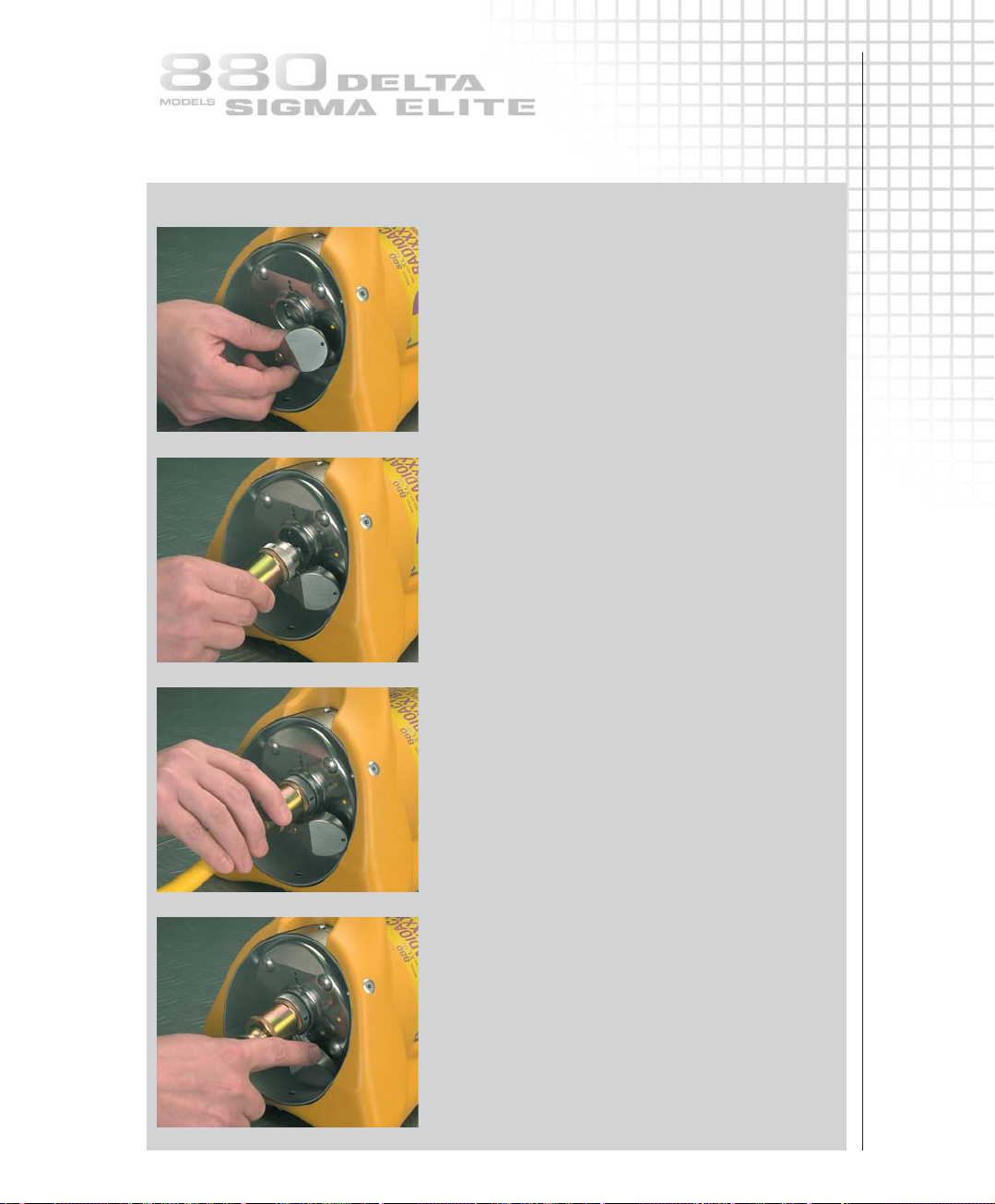
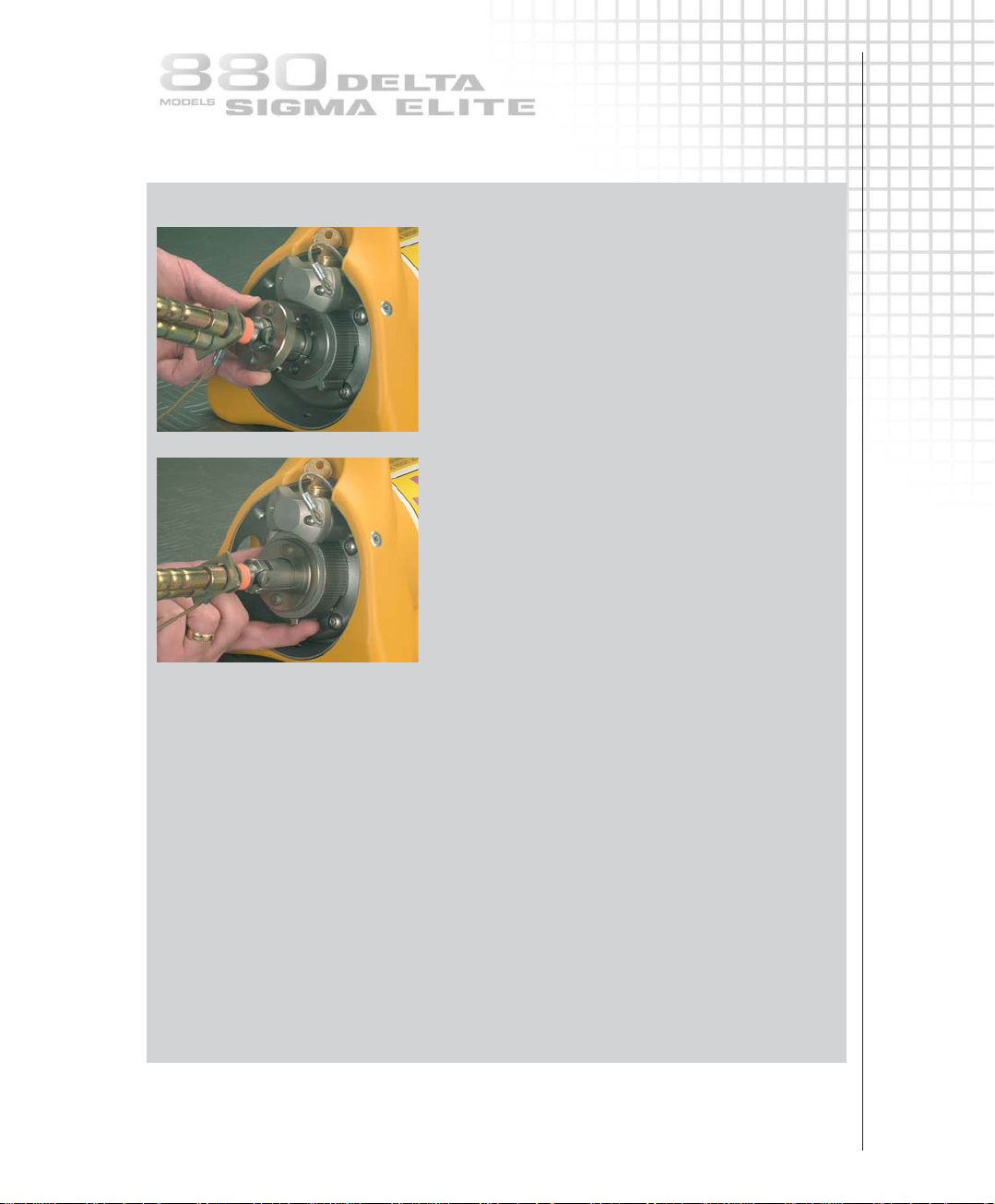
Connecting the source guide tube(s)
The source guide tubes must always be attached to the outlet port of the device before
connecting the remote controls in the set-up for a radiographic exposure.
Connect the source guide tube(s) to the exposure device outlet port as shown.
2.3
OPERATING INSTRUCTIONS
STEP 2
1
2
4
3
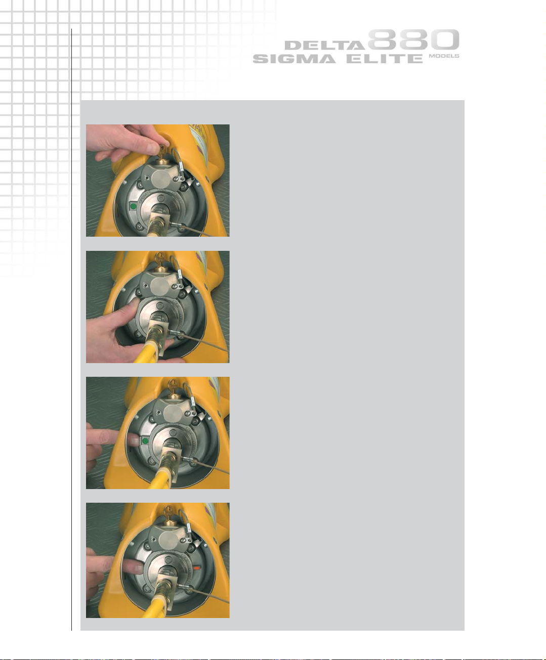
Connecting the source guide tube(s)
Simultaneously pull and rotate the
spring-loaded outlet port cover a quarter of
a turn in a clockwise direction.
Insert the bayonet fitting of the source guide
tube into the exposed outlet port.
Align the GREEN MARKINGS on the bayonet
fitting and outlet port.
Rotate a quarter of a turn counter-clockwise.
Rotate the spring-loaded outlet port cover
an additional 60 degrees in a clockwise direction
until it stops.
STEP 3
OPERATING INSTRUCTIONS
2.4
STEP 2
WARNING
Ensure that the available length of the control cable is greater than the total length
of the source guide tubes. See the technical specifications section for details.
If the remote control conduits are shorter than the total length of the
source guide tubes:
1 The source assembly cannot be projected all the way to the source stop of the
terminating source guide tube and be correctly positioned for the exposure.
2 The source assembly may not reach a collimator; therefore, restricted area dose rates
may be higher than expected.
3 The control cable may be cranked right off the drive wheel of remote controls
that are not be fitted with a safety retaining spring. This scenario must be treated
as an EMERGENCY.
Remote control conduit layout
Lay out the remote control conduits as straight as possible, with no bend radii less than
about 36in (approximately 1m).
Avoid any risk of crushing the remote control conduits by falling objects, moving vehicles or
closing doors, etc.
The remote control crank mechanism (operator's hand-crank) should be placed as far away
from the source focal position as possible (preferably behind shielding).
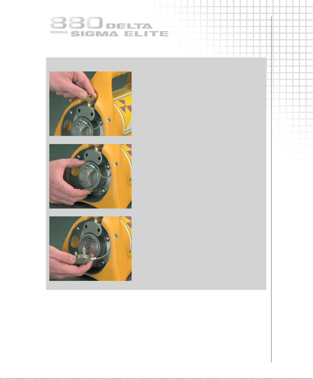
Connecting the remote control cable
Connect the control cable to the source projector as shown.
2.5
OPERATING INSTRUCTIONS
STEP 3
1
2
3
Connecting the remote control cable
Unlock the plunger lock with
the key.
Turn the selector ring
from LOCK to CONNECT.
The protective cover will disengage
from the projector.
STEP 3
OPERATING INSTRUCTIONS
2.6
4
5
6
7
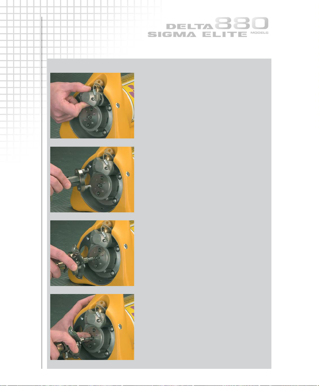
Connecting the remote control cable
Insert the protective cover into the lock housing
during use of the device.
Check the control cable and source assembly
connectors using the NO GO gauge according
to the daily inspection section.
Remove the protective rubber cap from the remote
control connector.
Slide the remote control connector assembly's
collar back and open the jaws to expose the male
portion of the control cable connector
(i.e. the ball-end on the control cable connector).
Press back the spring-loaded locking pin of
the source assembly connector with a thumb-nail
and engage the male and female portions of
the connectors.
Release the locking pin of the source assembly
connector and check that the connection is secure.
Use the NO GO gauge to check the gap between
the joined connectors during the daily inspection.
2.7
OPERATING INSTRUCTIONS
STEP 3
8
9
Connecting the remote control cable
Close the jaws of the control cable connector
over the joined connectors.
Slide the remote control connector assembly collar
over the connector jaws.
NOTE The control cable connector, when properly
installed with the selector ring in the CONNECT
position, displaces anti-rotation lugs which allows
the selector ring to be rotated to the LOCK position
and when required, through to the OPERATE position.
Push and hold the remote control connector
assembly collar flush against the exposure device’s
locking mechanism and rotate the selector ring
from CONNECT to LOCK. The selector ring can
be secured in this position by engaging the
plunger lock.
Do not rotate past LOCK.
The remote control cable connector is now secured
into the exposure device's locking mechanism.
Keep the exposure device in the LOCK position
until ready to start the exposure.
Checks before exposure of the source
Verify that the source guide tubes are attached to the outlet port.
Verify that the remote control connector assembly is correctly connected to the exposure
device’s locking mechanism.
Ensure that no personnel are inside the Restricted Area or exposure room.
Ensure that the proper signs are posted and required warnings are in operation.
NOTE
If the remote control is fitted with an additional lock, release this lock and apply a
forward motion to the control crank handle, as if exposing the source, until a resistance
is felt. Release the control crank handle and proceed with the next step.
CAUTION
Do not apply excessive force to the control crank handle in the expose direction as this could
cause the source assembly to move forward out of the stored position when the lock slide
is released. Do not retract the control cable and apply the control crank brake. Leave the
control crank and the control cable in a neutral tension position.
OPERATING INSTRUCTIONS
2.8
STEP 4
1
2
4
3
Projecting and retracting the source assembly
Unlocking
If engaged, unlock the exposure device's
plunger lock with the key.
Rotate the selector ring to the OPERATE position.
Ensure there is no tension/force in either direction
on the control cable.
Push the lock slide GREEN MARKING laterally
from left to right (as seen behind the projector)
until the lock slide RED MARKING fully appears
on the right side of the selector ring and you
feel or hear the sleeve snap into the slide.
When the GREEN MARKING is visible,
the source assembly is locked into the secured
position within the exposure device.
When the RED MARKING is visible, the source
assembly is free to be projected from, and retracted
to, the projector.
Ensure all personnel leave the immediate area.
Go to the remote control crank.
If an odometer is fitted, adjust the reset knob
to read zero.
The source assembly can now be projected.
STEP 4
2.9
OPERATING INSTRUCTIONS
Projecting
Rapidly rotate the control crank handle in the EXPOSE direction (counter-clockwise) to move
the source assembly out of the exposure device to the radiographic focal position.
The control crank handle will stop turning when the source reaches the source stop.
Do not use excessive force.
The odometer (if fitted) will indicate the approximate total distance traveled,
7ft (2.1m) for each guide tube section.
Set the brake to ON to prevent movement of the source assembly during the
radiographic exposure.
Start timing the radiographic exposure from the moment the source assembly reaches
the exposure head.
Survey meter readings observed during the projection operation should increase
rapidly from background to a high level as the source emerges from the projector.
Then readings should fall as the source moves out towards the focal point,
fall sharply as the source enters a collimator (if used) and remain steady throughout
the exposure.
Actual survey meter readings will depend on the source activity, distance, collimators
and shielding. The sequence of changes should be observed and the readings noted.
During retraction of the source assembly from the exposure head to the exposure device,
the sequence will reverse. The survey meter should indicate a continually increasing
radiation level as the source assembly is retracted, then drop to background when the
source assembly is stored in the exposure device.
During the radiographic exposure, use the survey meter to check the boundary dose
rate, but spend as little time as possible in and near the restricted area to minimize
personal exposure.
STEP 4
OPERATING INSTRUCTIONS
2.10
Retracting
At the end of the required exposure time, set the brake to OFF and rapidly turn
the crank handle in the RETRACT (clockwise) direction until it no longer moves.
You may hear the lock slide ‘click’ back into its original position depending on
the ambient noise level at the job site. From the control crank you may be able
to observe the GREEN MARKING on the slide bar.
Apply a slight amount of forward pressure on the crank handle as if to expose
the source to ensure that the positive locking mechanism has actuated.
Allow the crank handle to return to a neutral position, thereby relieving any tension
(force) on the control cable that would cause source movement when unlocking the
projector. At this point, the source cannot be moved out of the stored position.
In the unlikely event the lock slide moves toward the lock position before the source is
fully stored in the exposure device, turn the crank handle in the RETRACT (clockwise)
direction until it stops turning. (The lock slide is designed to lock on the stop ball, not the
control cable). Do not use excessive force. The source assembly will be in the exposure device
but not in the fully shielded position. Approach the exposure device, from the rear, with a
survey meter. The survey meter will measure approximately 40mR/hr (400µSv/hr) at the rear
plate of the exposure device when a 100Ci. (3.7TBq) source is in use.
CAUTION
Remain clear of the front of the exposure device (outlet port side) to minimize personal
exposure. Reset the lock slide to the open position. Return to the control crank and turn the
crank handle in the RETRACT (clockwise) direction and store the source assembly in the
normal manner.
The odometer (if supplied) should read approximately zero when the source assembly has
returned to the projector.
Confirmatory survey
Approach the exposure device while observing the survey meter - observe the
GREEN MARKING on the lock slide and survey the exposure device. The survey meter should
indicate the same radiation level as observed before the exposure. Note particularly the
outlet port reading.
Survey the entire length of source guide tube with the survey meter. If the meter shows a
sharp increase, the source is exposed or incompletely shielded.
If the source is still exposed, attempt to store it properly by cranking the source a short
distance toward the exposure head and retracting it, repeating if necessary.
Locking the exposure device
When the source assembly is properly stored in the projector, rotate the selector ring
from the OPERATE position to the LOCK position and secure it with the plunger lock.
Remove and safeguard key.
WARNING
If after several attempts to return the source assembly, the selector ring cannot be
rotated to the lock position (do not use excessive force) or the lock slide is not
actuated, one must suspect an accident in which the source assembly may have
become disconnected or stuck outside the projector, giving rise to a very high
radiation field. Treat the situation as an EMERGENCY.
STEP 5
2.11
OPERATING INSTRUCTIONS
Dismantling equipment
Remote control unit
Unlock the exposure device and then rotate the selector ring from LOCK to CONNECT.
The remote control connector will partially disengage from the exposure device's
locking mechanism.
Completely disengage the remote controls from the exposure device by disengaging the
control cable connector from the source assembly connector. Place the protective cover
over the remote control's connecting plug assembly to exclude dirt and protect the control
cable connector from damage. Roll the remote control conduits loosely for easier handling
and transport.
Reinstall the locking mechanism's protective cover, hold in place and rotate the selector
ring to the LOCK position. Push in the plunger lock and remove the key to lock the
exposure device.
Source guide tubes
Remove the source guide tube attached to the exposure device outlet port by:
1 Rotating the spring-loaded outlet cover 60 degrees in a counter-clockwise direction.
2 Grasp the source guide tube fitting and rotate a quarter of a turn in a clockwise direction.
This action will allow removal of the source guide tube from the outlet port.
3 Simultaneously pull and rotate the spring-loaded outlet port cover a quarter of a turn in a
counter-clockwise direction.
Place the protective covers on the fittings of each source guide tube used to exclude dirt and
protect the swaged fittings. Source guide tubes should be rolled up loosely for easier
handling and transport.
Surveying
After installing the locking mechanism’s protective cover and the outlet port cover, survey
the entire circumference of the exposure device with the survey meter to ensure the source
is fully shielded and properly secured. The survey should not measure more than 200mR/hr
(2mSv/hr) on any surface of the exposure device and should indicate the same measurement
as the initial survey.
Storage
Lock the exposure device and secure it in a clean dry storage area where it cannot
be tampered with or removed by unauthorized personnel. Perform a storage survey
on the surface of the exposure device to verify the dose rate is less than 200mR/hr
(2mSv/hr) and record.
A radioactive material warning notice must be posted on the door or entrance of
the storage area. The door or entrance must be locked to prevent access by
unauthorized personnel.
 Loading...