

SEW-Eurodrive MOVIDRIVE compact MCF, MOVIDRIVE Series, MOVIDRIVE compact MCS_4A, MOVIDRIVE compact MCV, MOVIDRIVE MD_60A User Manual
Edition
MOVIDRIVE® Serial Communication
11/2001
Manual
1053 1610 / EN
SEW-EURODRIVE
Contents
1 Important Notes...................................................................................................... 4
2 Introduction ............................................................................................................ 5
2.1 Overview of serial interfaces.......................................................................... 5
2.2 Technical data................................................................................................ 8
2.3 MOVILINK® and system bus......................................................................... 9
3 Installation ............................................................................................................ 12
3.1 System bus (SBus) installation .............................. .... ... ... ... .... ..................... 12
3.2 RS-485 interface installation ........................................................................ 14
3.3 RS-232 interface installation ........................................................................ 16
4 RS-485 Communication....................................................................................... 17
4.1 Telegrams.................................................................................................... 17
4.2 Addressing and transmission proces s ....................... .................................. 20
4.3 Data contents and PDU types...................................................................... 29
P6..
P60.
P600
5 System Bus (SBus) .............................................................................................. 37
5.1 Slave data exchange via MOVILINK® ......................................................... 37
5.2 Setting parameters via the CAN bus............................................................ 42
5.3 Master data exchange via MOVILINK®....................................................... 47
5.4 Master/slave operation via the SBus............................................................ 50
5.5 Data exchange via variable telegrams......................................................... 51
5.6 Project planning example for SBus............................................ ... ... ... ......... 62
6 Operation and Service.......................... ... ... ... ............................................. .... ... .. 64
6.1 Startup problems with the SBus................................................................... 64
6.2 Return codes for parameter setting.............................................................. 65
7 Parameter List .................................................................................... .................. 67
7.1 Explanation of the table header .................................... ... ............................ 67
7.2 Complete parameter list, sorted by parameter numbers.............................. 68
7.3 Quantity and conversion index................................................................ ..... 84
8 Index...................................................................................................................... 87
MOVIDRIVE® Serial Communication
3
1
1 Important Notes
• This manual does not replace the detailed operating instructions!
• Installation and startup only by trained personnel observing applicable
accident prevention regulations and the MOVIDRIVE
®
operating instructions!
Documentation • Read through this manual carefully before you commence installation and startup of
MOVIDRIVE
®
drive inverters with a serial communications link (RS-232, RS-485,
system bus).
• This manual assumes that the user has access to and is familiar with the
MOVIDRIVE
®
documentation, in particular the MOVIDRIVE® system manual.
• In this manual, cross references are marked with "→". For example, (→ Sec. X.X)
means: Further information can be found in section X.X of this manual.
• A requirement of fault-free operation and fulfillment of any rights to claim under
guarantee is that the documentation is observed.
Bus systems General safety notes on bus systems:
This communication system allows you to match the MOVIDRIVE
®
drive inverter to the
specifics of your application to a very high degree. As with all bus systems, there is a
danger of invisible, external (as far as the inverter is concerned) modifications to the
parameters which give rise to changes in the inverter behavior. This may result in
unexpected (not uncontrolled, though!) system behavior.
Safety and
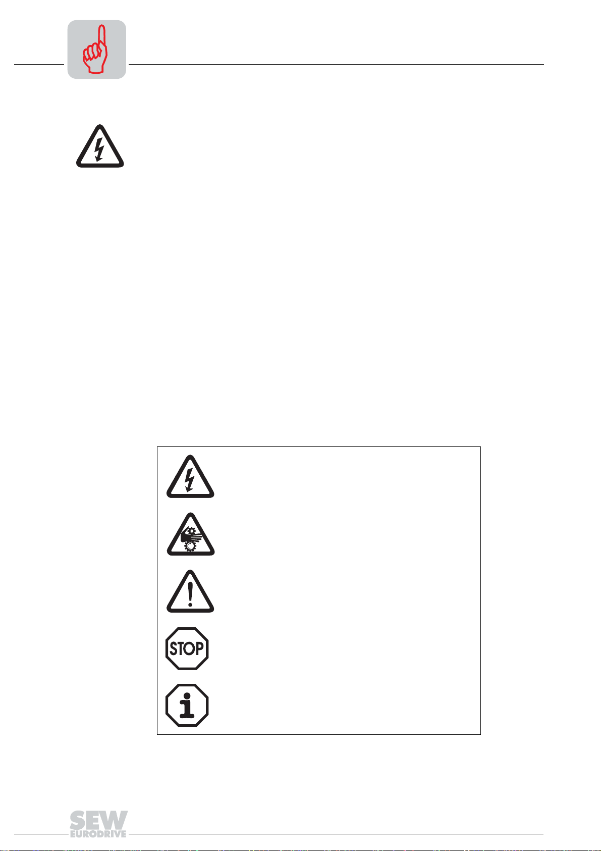
Always follow the safety and warning instructions contained in this publication!
warning
instructions
Electrical hazard
Possible consequences: Severe or fatal injuries.
Hazard
Possible consequences: Severe or fatal injuries.
Hazardous situation
Possible consequences: Slight or minor injuries.
Harmful situation
Possible consequences: Damage to the unit and the
environment.
Tips and useful information.
4
MOVIDRIVE® Serial Communication
2 Introduction
2.1 Overview of serial interfaces
The following serial interfaces are provided as standard with MOVIDRIVE® drive
inverters for serial communication:
1. System bus (SBus) = CAN bus to CAN specification 2.0, parts A and B.
2. RS-485 interface to EIA standard
Overview of serial interfaces
2
MOVIDRIVE
MD_60A
®
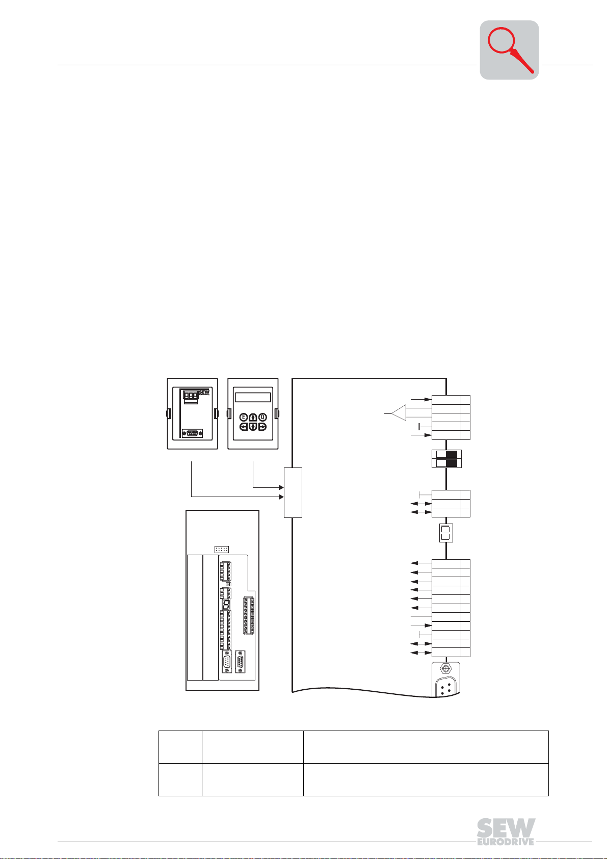
System bus (SBus):
The system bus (SBus) is routed to terminals X12:2/3 in MOVIDRIVE
®
MD_60A drive
inverters.
RS-485 interface:
The RS-485 interface is routed to the TERMINAL option slot and, in parallel, to terminals
X13:10/11 in MOVIDRIVE
®
MD_60A drive inverters.
Either the "DBG11A keypad" or the "USS21A serial interface" can be connected to the
TERMINAL option slot.
0V5 - +
RS485
RS232
USS21A
EQ
DBG11A
CONTROL
TERMINAL
SBusHigh
SBusLow
X11:
1
+
-
REF1
AI11
AI12
AGND
REF2
ON OFF
2
3
4
5
S 11
S 12
X12:
DGND
1
SC11
2
SC12
3
MOVIDRIVE
Fig. 1: Serial interfaces on MOVIDRIVE® MD_60A
X12:1
X12:2
X12:3
X13:10
X13:11
®
Serial Communication
TERMINAL
CONTROL
OPTION2
OPTION1
DGND: Ref. potential
SBus high
SBus low
ST11: RS-485+
ST12: RS-485-
X13:
DIØØ
1
DIØ1
2
DIØ2
3
DIØ3
4
DIØ4
5
DIØ5
6
DCOM
7
VO24
8
DGND
RS-485+
RS-485-
ST11
ST12
9
10
11
X14:
1
6
05274AXX
CAN bus to CAN specification 2.0, parts A and B, transmission
technology to ISO 11898, max. 64 stations, terminating resistor
(120 Ω) can be activated using DIP switches
EIA standard, 9600 baud, max. 32 stations
Max. cable length 200 m (660 ft) in total
Dynamic terminating resistor with fixed installation
5
2
Overview of serial interfaces
MOVIDRIVE®
compact
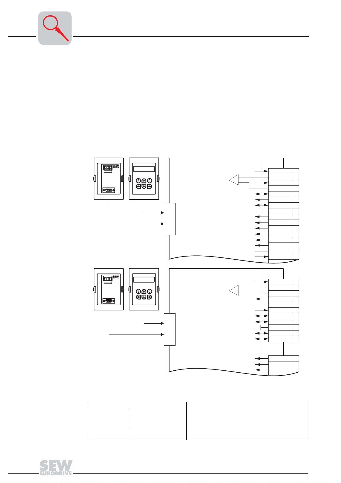
System bus (SBus):
• The system bus (SBus) is routed to terminals X10:5/7 in MOVIDRIVE
®
compact
MCF/MCV/MCS4_A drive inverters.
• The system bus (SBus) is routed to terminals X10:7/8 and X10:10/11 in
MOVIDRIVE
®
compact MCH4_A drive inverters. Terminals X10:7 and X10:10 are
electrically connected, as are terminals X10:8 and X10:11.
RS-485 interface:
The RS-485 interface is routed to the TERMINAL option slot in MOVIDRIVE
®
compact
drive inverters.
Either the "DBG11A keypad" or the "USS21A serial interface" can be connected to the
TERMINAL option slot.
0V5 - +
RS485
RS232
USS21A
EQ
DBG11A
MCF/MCV/MCS4_A
+
-
SBusHigh
SBusLow
TERMINAL
X10:
AGND
DCOM
REF1
AI11
REF2
AI12
SC11
AI21
SC12
DIØØ
DIØ1
DIØ2
DIØ3
DIØ4
DIØ5
VO24
1
2
3
4
5
6
7
8
9
10
11
12
13
14
15
16
MCH4_A
0V5 - +
RS485
RS232
USS21A
EQ
DBG11A
TERMINAL
+
-
SBusHigh
SBusLow
SBusHigh
SBusLow
Fig. 2: Serial interfaces on MOVIDRIVE® compact
* Only use these terminals if S12 = OFF; connect terminating equipment to SC11/SC12.
MOVIDRIVE
X10:5
X10:7
MOVIDRIVE
X10:7/10
X10:8/11
®
compact MCF/MCV/MCS4_A
SBus high
SBus low
®
compact MCF/MCV/MCS4_A
SBus high
SBus low
CAN bus to CAN specification 2.0, parts A and B
Transmission system to ISO 11898
max. 64 stations
Terminating resistor (120 Ω) can be activated using
DIP switches
X10:
AGND
DGND
SC21*
SC22*
X11:
REF1
AI11
AI12
AI21
REF2
SC11
SC12
DIØØ
DIØ1
DIØ2
05275AXX
1
2
3
4
5
6
7
8
9
10
11
1
2
3
6
MOVIDRIVE® Serial Communication
Overview of serial interfaces
2
USS21A (RS-232
and RS-485)
Startup, operation and service are possible from the PC via the serial interface. The
SEW MOVITOOLS software is used for this purpose. It is also possible to transfer
parameter settings to several MOVIDRIVE
MOVIDRIVE
®
can be equipped with isolated RS-232 and RS-485 interfaces. The RS-
®
drive inverters via PC.
232 interface is configured as a 9-pin sub D female connector (EIA standard) and the
RS-485 interface as a terminal connection. The interfaces are accommodated in a
housing for plugging onto the inverter (TERMINAL option slot). The option can be
plugged on during operation. The transmission rate of both interfaces is 9600 baud.
DBG11A and USS21A are connected to the same inverter slot (TERMINAL) and cannot
be used at the same time.
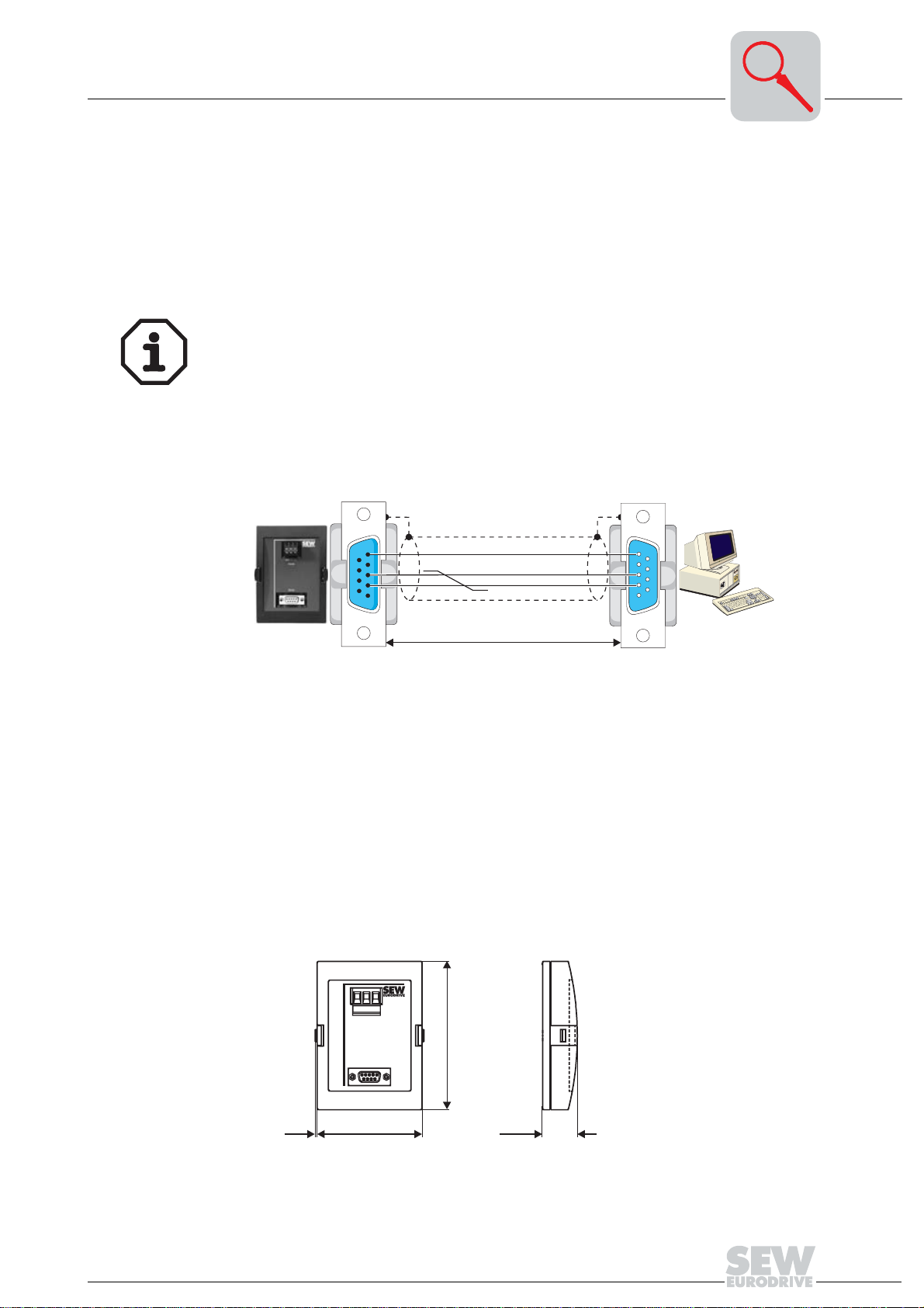
RS-232 interface Use a commercially available serial interface cable (shielded!) for connecting a PC to
MOVIDRIVE
®
with the USS21A option.
Important: 1:1 cabling
USS21A
5
55
3
33
22
2
GND (ground)
TxD
RxD
5
55
3
33
2
22
PC COM 1-4
Fig. 3: Connection cable USS21A – PC
RS-485 interface A maximum of 16 MOVIDRIVE
(max. total cable length 200 m (660 ft)) via the RS-485 interface of the USS21A.
Dynamic terminating resistors are permanently installed, so do not connect any external
terminating resistors.
Unit addresses 0 – 99 are permitted with multipoint connections. In this case, the "peerto-peer connection" must not be selected in MOVITOOLS. The communications
address in MOVITOOLS and the RS-485 address of the MOVIDRIVE
be identical.
Dimensions
0V5 - +
RS485
RS232
max. 5 m (16.5 ft)
9-pin sub D connector (female)9-pin sub D connector (male)
02399AEN
®
units can be networked for communications purposes
®
unit (P810) must
120 (4.72)
MOVIDRIVE
1.5 (0.06)
Fig. 4: USS21A dimensions in mm (in)
®
Serial Communication
85 (3.35)
28.5 (1.12)
01003BXX
7
2
2.2 Technical data
System bus
(SBus)
Technical data
Standard CAN specification 2.0 parts A and B
Baud rate either 125, 250, 500 or 1000 kbaud, factory setting 500 kbaud
ID range 3 – 1020
Address can be set with parameter P813: 0 – 63
Number of process
data words
Line length depending on the baud rate, max. 320 m
Number of stations max. 64
fixed setting: 3 PD
Co
RS-485 interface
RS-232 interface
Only when P816 "SBus baud rate" = 1000 kbaud:
Do not combine MOVIDRIVE
®
compact MCH42A units with other MOVIDRIVE® units in
the same system bus combination.
The units are allowed to be mixed at baud rates ≠ 1000 kbaud.
Standard RS-485
Baud rate 9.6 kbaud
Start bits 1 start bit
Stop bits 1 stop bit
Data bits 8 data bits
Parity 1 parity bit, supplementing to even parity
Line length 200 m between two stations
Number of stations 1 master and max. 31 slaves
Standard DIN 66020 (V.24)
Baud rate 9.6 kbaud
Start bits 1 start bit
Stop bits 1 stop bit
Data bits 8 data bits
Parity 1 parity bit, supplementing to even parity
Line length max. 5 m
Number of stations 1 master + 1 slave (peer-to-peer connection)
8
MOVIDRIVE® Serial Communication

MOVILINK® and system bus
2
2.3 MOVILINK
MOVILINK®
protocol
®
and system bus
This document provides a detailed description of the MOVILINK® serial interface
protocol for the RS-485 interfaces of MOVIDRIVE
®
drive inverters. You can control the
inverter and set its parameters via the RS-485 interface.
However, please bear in mind that this communications variant is a proprietary
communication system for low-end applications.
The low speed of transmission and the significant time and effort needed to implement
the various automation systems mean that SEW recommends the following fieldbus
systems as the professional method of linking SEW inverters to machine control
systems:
• PROFIBUS-DP
• INTERBUS
• INTERBUS with fiber optic cable
•CAN
• CANopen
• DeviceNet
These fieldbus systems are supported by SEW and by all well-known manufacturers of
automation systems.
The MOVILINK
MOVIDRIVE
®
protocol for serial interfaces in the new SEW range of inverters,
®
and MOVIMOT®, enables you to set up a serial bus connection between
a higher-level master and several SEW inverters. For example, masters may take the
form of programmable logic controllers, PCs or even SEW inverters with PLC functions
plus®
(IPOS
). Generally speaking, the SEW inverters function as slaves in the bus
system.
The MOVILINK
®
protocol allows both of the following applications to be implemented:
automation tasks such as control and parameter setting of the drives by means of
cyclical data exchange, startup and visualization tasks.
Features The principal features of the MOVILINK
• Support for the master/slave structure via RS-485 with one master (single master)
and at most 31 slave stations (SEW inverters).
• Support for peer-to-peer connection via RS-232.
• User-friendly implementation of the protocol in a simple and reliable telegram
structure with fixed telegram lengths and a unique start identifier
• Data interface to the basic unit in accordance with the MOVILINK
means the user data sent to the drive are transmitted to the inverter in the same way
as via the other communications interfaces (PROFIBUS, INTERBUS, CAN,
CANopen, DeviceNet, etc.).
• Access to all drive parameters and functions, i.e. it can be used for startup, service,
diagnosis, visualization and automation tasks
• Startup and diagnostic tools on the basis of MOVILINK
SHELL and MOVITOOLS/SCOPE).
®
protocol are:
®
profile. This
®
for PC (e.g. MOVITOOLS/
MOVIDRIVE
®
Serial Communication
9
2
MOVILINK® and system bus
System bus
(SBus)
The SBus is a CAN bus in accordance with the CAN specification 2.0, parts A and B. It
supports all services in the SEW MOVILINK
plus®
IPOS
variables via the SBus independently of the profile.
®
unit profile. In addition, you can exchange
The unit behavior of the inverter which forms the basis of CAN operation is referred to
as the unit profile. It is independent of any particular fieldbus and is therefore a uniform
feature. This provides you, the user, with the opportunity of developing applications
regardless of the fieldbus.
MOVIDRIVE
®
offers digital access to all drive parameters and functions via the SBus.
The drive inverter is controlled via high-speed process data. These process data
telegrams let the user enter setpoints, such as the setpoint speed, ramp generator time
for acceleration/deceleration, etc. and trigger various drive functions such as enable,
control inhibit, normal stop, rapid stop, etc. You can also use these telegrams to read
back actual values from the drive inverter, such as the actual speed, current, unit status,
error number and reference signals.
The exchange of parameter data via the MOVILINK
®
parameter channel lets you create
applications in which all important drive parameters are stored in the programmable
master controller. This means there is no need to manually set the parameters on the
drive inverter itself, which is frequently a rather time-consuming task. IPOS
plus®
provides the MOVLNK command for the exchange of parameter data and process data
with other MOVILINK
via IPOS
plus®
and control other units.
®
stations. As a result, MOVIDRIVE® can operate as the master
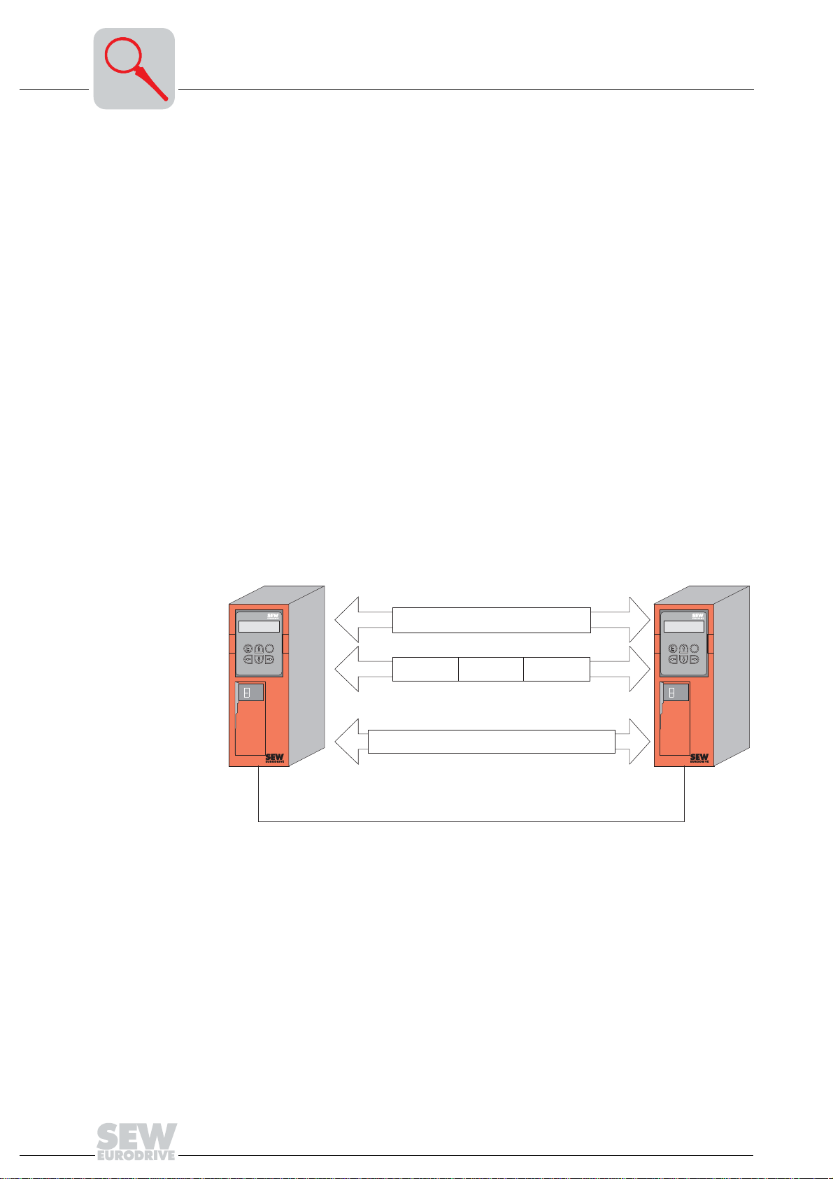
The process data and the drive parameters can be sent to a synchronization telegram
synchronously or asynchronously.
®
Parameter
PD1 PD2 PD3
PD2
PD1 PD2 PD3
PD3
Q
E
02244BEN
plus®
IPOS
Q
E
plus®
IPOS
Max. 8 data bytes = 2 variables, each 32 bit
Fig. 5: Variants of SBus communication
PD1
System bus (SBus)
MOVILINK protocol
Variable exchange
Using the SBus requires additional monitoring functions such as time monitoring (SBus
timeout delay) or special emergency-off concepts. You can adapt the monitoring
functions of MOVIDRIVE
®
specifically to your application. You can determine which
error response the drive inverter should trigger in the event of a timeout. A rapid stop is
a good idea for many applications, although this can also be achieved by "freezing" the
last setpoints so the drive continues operating with the most recently valid setpoints (e.g.
conveyor belt). You can still implement emergency-off concepts which are independent
of the bus and use the terminals of the drive inverter because the functions of the control
terminals are still active when the SBus is in operation.
10
MOVIDRIVE® Serial Communication

MOVILINK® and system bus
The MOVIDRIVE® drive inverter offers you numerous diagnostic options for startup and
service purposes. An easy-to-use diagnostics tool is provided in the MOVITOOLS/
SHELL PC software. This software makes it possible to call up a detailed display of the
bus and unit status as well as setting all drive parameters.
2
Variable telegrams Not only does the cyclical and acyclical variable exchange function create an interface
via which variables can be exchanged between several MOVIDRIVE
possible to implement partial functions for specific profiles in external units. These
external units may support the CANopen or DeviceNet protocol.
®
units, it is also
MOVIDRIVE
®
Serial Communication
11
3
System bus (SBus) installation
3 Installation
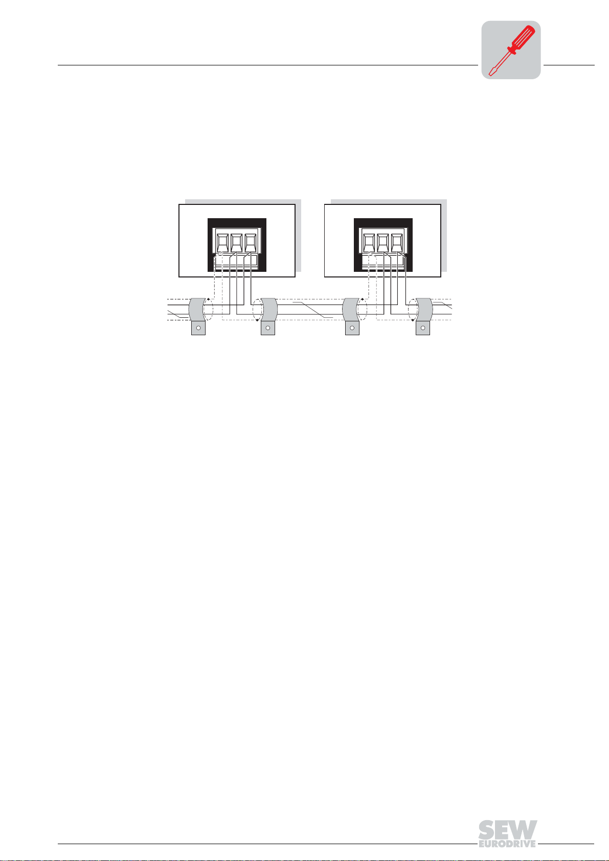
3.1 System bus (SBus) installation
Only when P816 "SBus baud rate" = 1000 kbaud:
Do not combine MOVIDRIVE
the same system bus combination.
The units are allowed to be mixed at baud rates ≠ 1000 kbaud.
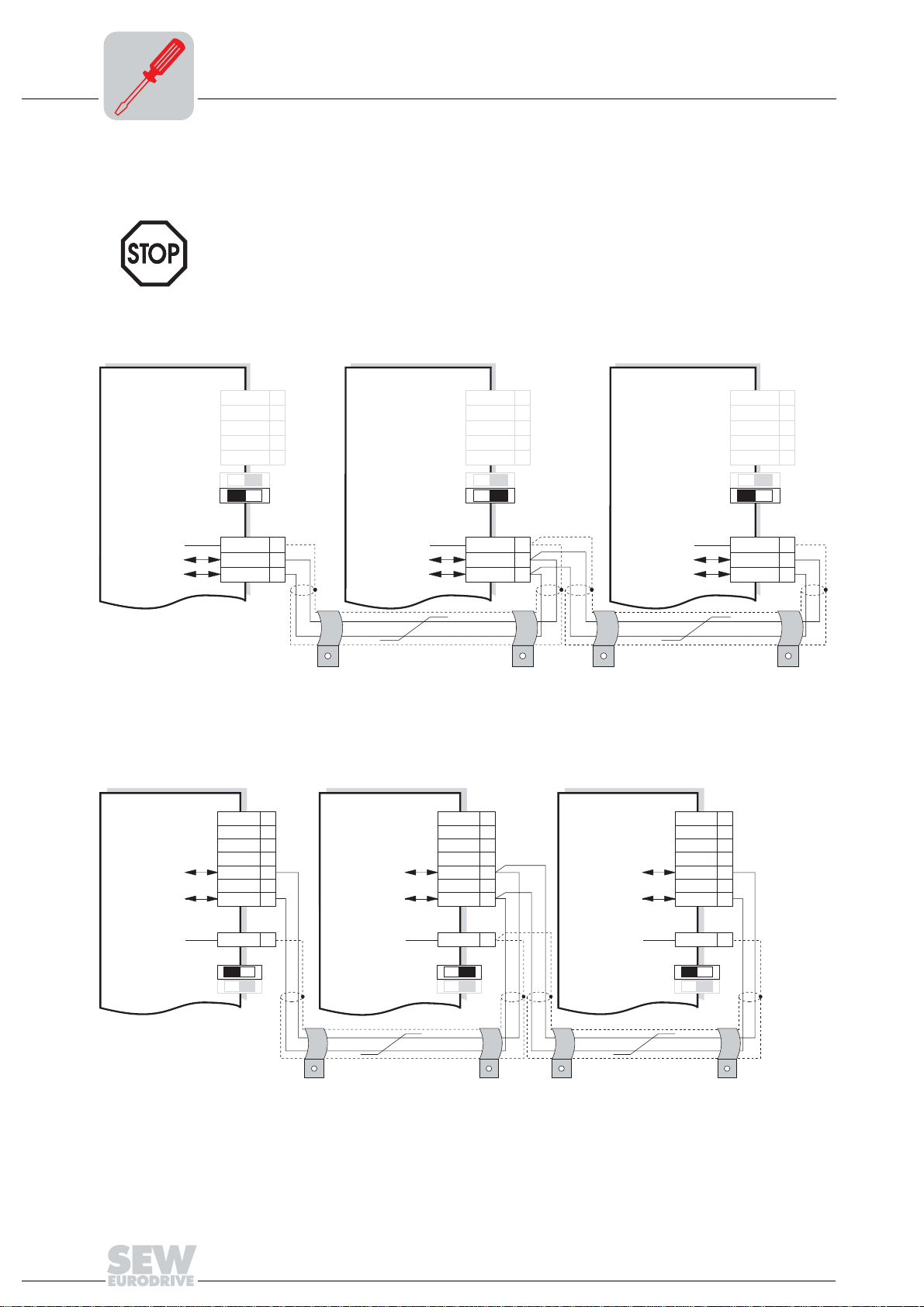
MOVIDRIVE® MD_60A
®
compact MCH42A units with other MOVIDRIVE® units in
Controlunit Controlunit Controlunit
Terminating resistor
Systembus
ref.potential
Systembushigh Systembushigh Systembushigh
Systembuslow Systembuslow Systembuslow
X11:
System bus
X12:
REF1
AI11
AI12
AGND
REF2
ON OFF
DGND
SC11
SC12
1
2
3
4
5
S 11
S 12
1
2
3
X11:
System bus
Terminating resistor
Systembus
ref.potential
X12:
REF1
AI11
AI12
AGND
REF2
ON OFF
DGND
SC11
SC12
1
2
3
4
5
S 11
S 12
1
2
3
Terminating resistor
Systembus
ref.potential
쵰쵰쵰쵰
Fig. 6: System bus connection MOVIDRIVE® MD_60A
MOVIDRIVE
®
compact MCF/MCV/MCS4_A
Controlunit Controlunit Controlunit
X10: X10: X10:
SC11
SC12
1
2
3
4
5
6
7
1
2
3
4
SC11
SC12
5
6
7
Systembushigh Systembushigh Systembushigh
Systembuslow Systembuslow Systembuslow
02205BEN
X11:
System bus
X12:
SC11
SC12
REF1
AI11
AI12
AGND
REF2
ON OFF
DGND
SC11
SC12
1
2
3
4
5
6
7
1
2
3
4
5
S 11
S 12
1
2
3
Reference
potential
System bus
Terminating resistor
DGND
17 17 17
ON OFF ON OFF ON OFF
S 12
S 11
Reference
potential
System bus
Terminating resistor
DGND
쵰쵰쵰쵰
Fig. 7: System bus connection MOVIDRIVE® compact MCF/MCV/MCS4_A
12
Reference
potential
System bus
S 12
S 11 S 11
Terminating resistor
02411AEN
DGND
S 12
MOVIDRIVE® Serial Communication
System bus (SBus) installation
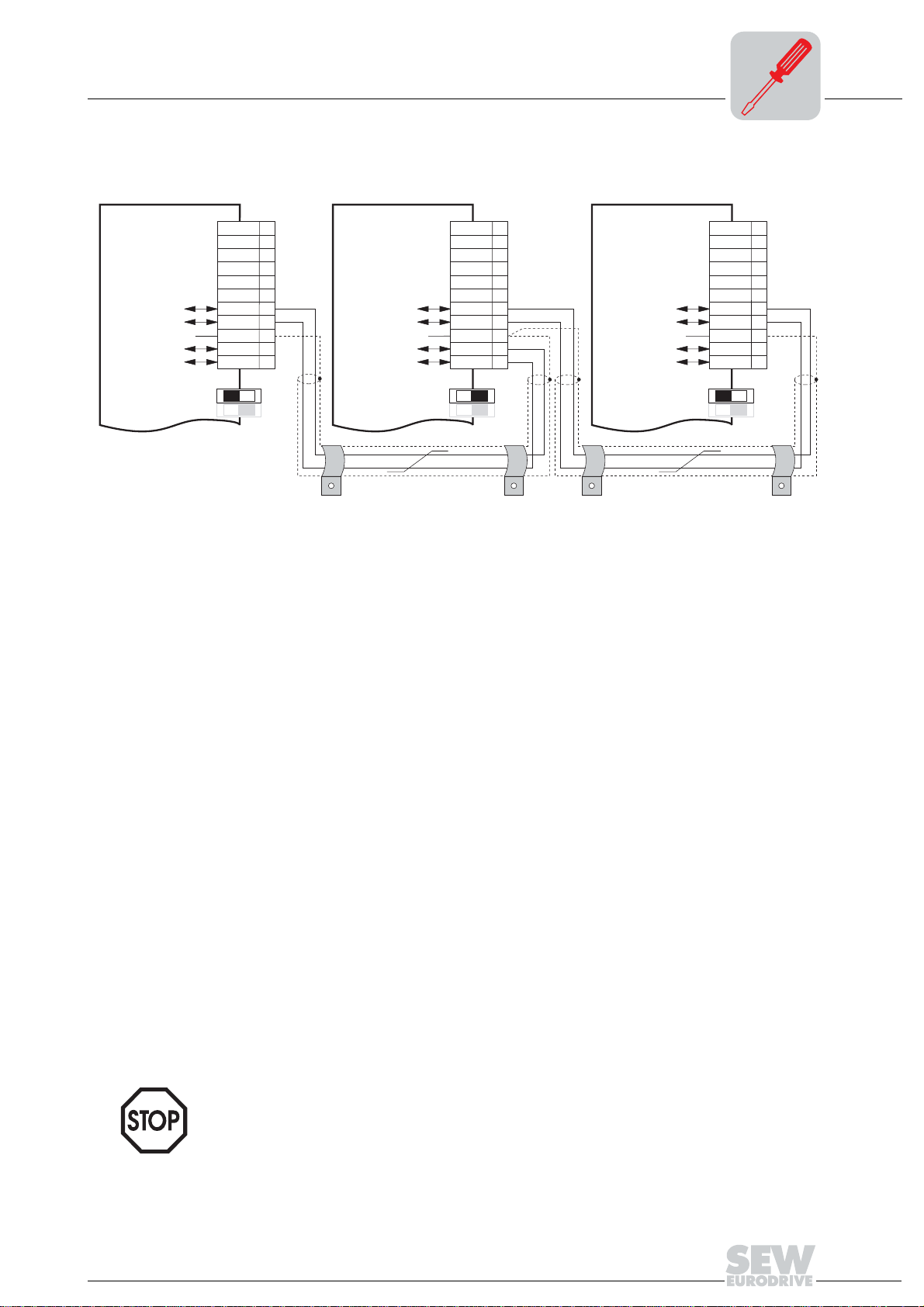
MOVIDRIVE® compact MCHS4_A
Controlunit Controlunit Controlunit
X10: X10: X10:
1
2
3
4
5
6
Systembushigh Systembushigh Systembushigh
Systembuslow Systembuslow Systembuslow
Referencepotential
Systembushigh Systembushigh Systembushigh
Systembuslow Systembuslow Systembuslow
System bus
Terminating resistor
ON OFF ON OFF ON OFF
7
SC11
8
SC12
9
DGND
10
SC21
11
SC22
S 12 S 12 S 12
S 11 S 11 S 11
Referencepotential
System bus
Terminating resistor
쵰쵰쵰 쵰
SC11
SC12
DGND
SC21
SC22
10
11
1
2
3
4
5
6
7
8
9
Referencepotential
Terminating resistor
System bus
SC11
SC12
DGND
SC21
SC22
3
1
2
3
4
5
6
7
8
9
10
11
Fig. 8: System bus connection MOVIDRIVE® compact MCH4_A
05210AEN
SBus MCH4_A: Connect the terminating equipment to SC11/SC12. SC21/SC22 are only active when S12 = OFF.
Cable
specification
• Use a 2-core twisted and shielded copper cable (data transmission cable with shield
comprising copper braiding). The cable must meet the following specifications:
– Conductor cross section 0.75 mm
2
(AWG 18)
– Cable resistance 120 Ω at 1 MHz
– Capacitance per unit length ≤ 40 pF/m (12 pF/ft) at 1 kHz
Suitable cables are CAN bus or DeviceNet cables, for example.
Shield contact • Connect the shield at either end to the electronics shield clamp of the inverter or the
master control and ensure the shield is connected over a large area. Also connect
the ends of the shield to DGND.
Line length • The permitted total line length depends on the baud rate setting of the SBus (P816):
– 125 kbaud → 320 m (1056 ft)
– 250 kbaud → 160 m (528 ft)
– 500 kbaud → 80 m (264 ft)
– 1000 kbaud → 40 m (132 ft)
Terminating
resistor
MOVIDRIVE
®
• Switch on the system bus terminating resistor (S12 = ON) at the start and finish of
the system bus connection. Switch off the terminating resistor on the other units
(S12 = OFF).
• There must not be any potential displacement between the units which are
connected together using the SBus. Take suitable measures to avoid a potential
displacement, e.g. by connecting the unit ground connectors using a separate lead.
Serial Communication
13
3
RS-485 interface installation
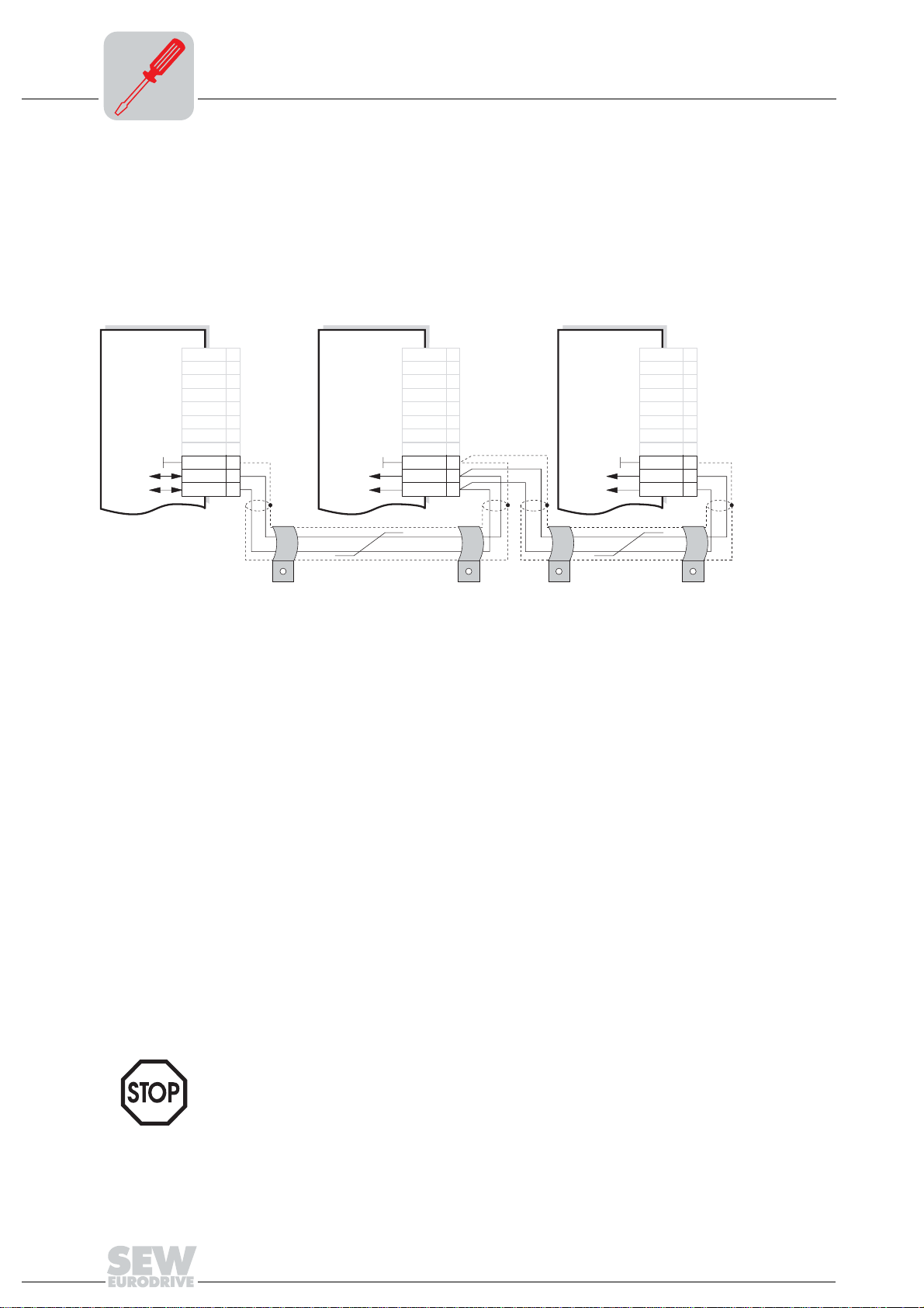
3.2 RS-485 interface installation
MOVIDRIVE®
MD_60A
The RS-485 interface is routed to terminals X13:10/11 and, in parallel, to the TERMINAL
option slot. The RS-485 interface can only be accessed via the TERMINAL option slot
when the "serial interface type USS21A" option is attached.
RS-485 connection via terminals X13:10/11
Controlunit Controlunit Controlunit
X13: X13: X13:
DIØØ
1
DIØ1
2
DIØ2
3
DIØ3
4
DIØ4
5
DIØ5
6
DCOM
7
VO24
8
DGND
RS-485+ RS-485+ RS-485 +
RS-485- RS-485- RS-485-
ST11
ST12
9
10
11
DIØØ
DIØ1
DIØ2
DIØ3
DIØ4
DIØ5
DCOM
VO24
DGND
ST11
ST12
1
2
3
4
5
6
7
8
9
10
11
쵰쵰쵰쵰
Fig. 9: RS-485 connection via X13:10/11
02206AEN
DIØØ
DIØ1
DIØ2
DIØ3
DIØ4
DIØ5
DCOM
VO24
DGND
ST11
ST12
1
2
3
4
5
6
7
8
9
10
11
Cable specification • Use a 2-core twisted and shielded copper cable (data transmission cable with shield
comprising copper braiding). The cable must meet the following specifications:
– Conductor cross section 0.5 – 0.75 mm
2
(AWG 20 – 18)
– Cable resistance 100 – 150 Ω at 1 MHz
– Capacitance per unit length ≤ 40 pF/m (12 pF/ft) at 1 kHz
The following cable is suitable, for example:
– BELDEN (www.belden.com), data cable type 3105A
Shield contact • Connect the shield at either end to the electronics shield clamp of the inverter or the
machine control and ensure the shield is connected over a large area. Also connect
the ends of the shield to DGND.
Line length • The permitted total line length is 200 m (660 ft).
Terminating
resistor
• Dynamic terminating resistors are fitted. Do not connect any external terminating
resistors!
• There must not be any potential displacement between the units which are
connected via RS-485. Take suitable measures to avoid a potential displacement,
e.g. by connecting the unit ground connectors using a separate lead.
14
MOVIDRIVE® Serial Communication
RS-485 interface installation
3
USS21A serial
interface
• With MOVIDRIVE® MD_60A drive inverters, the RS-485 interface can also be
accessed using the "serial interface type USS21A" option.
• With MOVIDRIVE
®
compact drive inverters, the RS-485 interface can only be
accessed using the "serial interface type USS21A" option.
RS-485 connection
via USS21A
USS21A USS21A
++
--
0V5 0V5
1
2
3
1
2
3
쵰쵰 쵰쵰
Fig. 10: RS-485 interface of the USS21A
00997CXX
Cable specification • Use a 2-core twisted and shielded copper cable (data transmission cable with shield
comprising copper braiding). The cable must meet the following specifications:
– Conductor cross section 0.5 – 0.75 mm
2
(AWG 20 – 18)
– Cable resistance 100 – 150 Ω at 1 MHz
– Capacitance per unit length ≤ 40 pF/m (12 pF/ft) at 1 kHz
The following cable is suitable, for example:
– BELDEN (www.belden.com), data cable type 3105A
Shield contact • Connect the shield at either end to the electronics shield clamp of the inverter and
ensure the shield is connected over a large area. Also connect the ends of the shield
to DGND.
EIA standard • Max. transmission rate 9600 baud
• Max. 32 stations (each unit with USS21A counts as two stations)
• Max. cable length 200 m (660 ft) in total
• Dynamic terminating resistor with fixed installation
MOVIDRIVE
®
Serial Communication
15
3
RS-232 interface installation
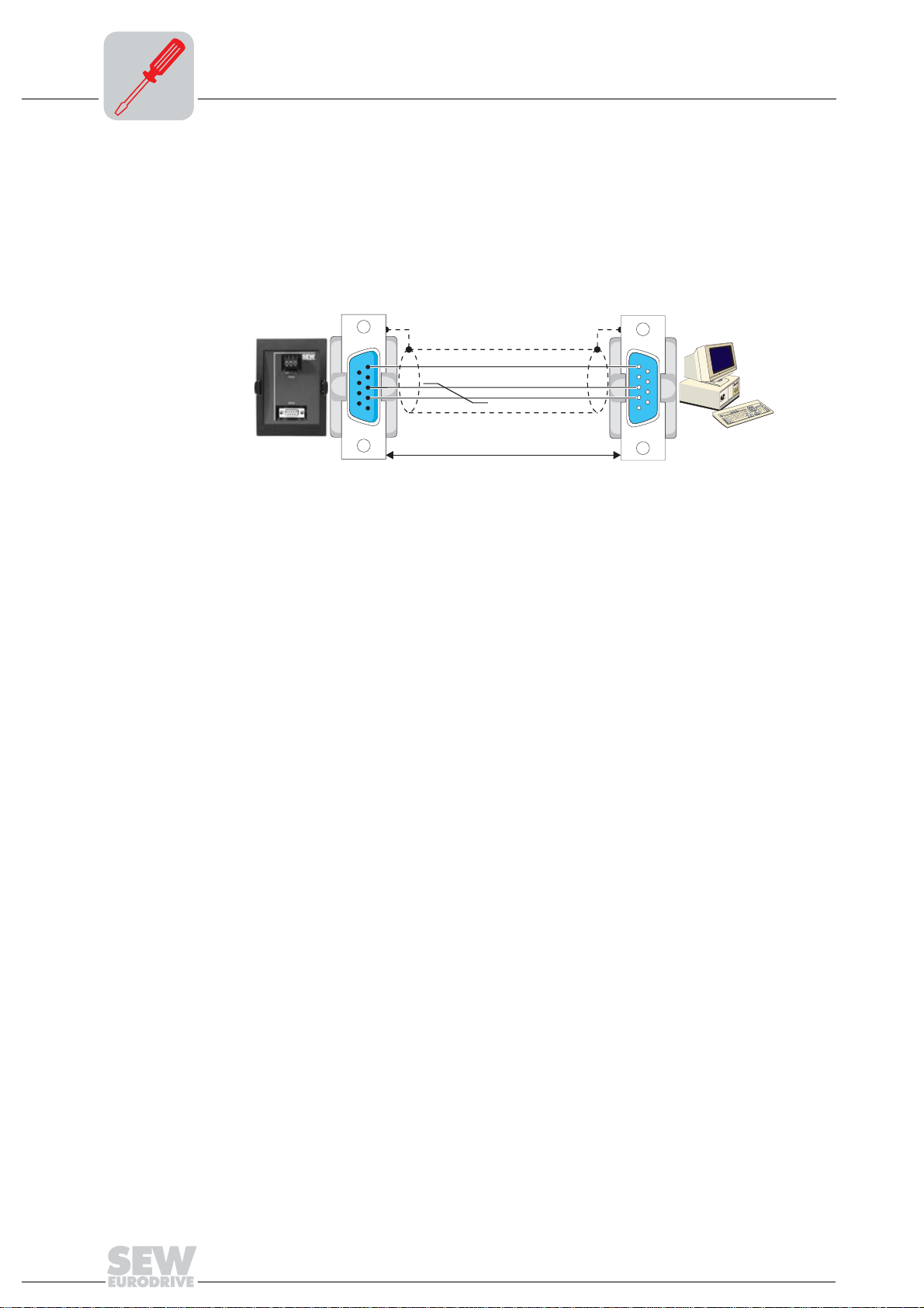
3.3 RS-232 interface installation
With MOVIDRIVE® MD_60A and MOVIDRIVE® compact, the RS-232 interface can only
be accessed using the "serial interface type USS21A" option.
RS-232
connection
• Use a shielded standard interface cable for connecting to the RS-232 interface.
Important: 1:1 cabling
USS21A
5
55
3
33
22
2
Fig. 11: PC connection via RS-232
GND (ground)
TxD
RxD
max. 5 m (16.5 ft)
5
55
3
33
2
22
9-pin sub D connector (female)9-pin sub D connector (male)
PC COM 1-4
02399AENdf
16
MOVIDRIVE® Serial Communication

Telegra ms
4 RS-485 Communication
4.1 Telegrams
Telegram traffic Both cyclical and acyclical data exchange are used in drive engineering. Cyclical
telegrams via the serial interface are used in automation applications, particularly for
drive control. The master station must ensure cyclical data exchange in this case.
4
Cyclical data
exchange
Acyclical data
exchange
Cyclical data exchange is used predominantly for controlling the inverters via the serial
interface. In this process, the master continuously sends telegrams containing setpoints
(request telegrams) to an inverter (slave) and then waits for a response telegram with
actual values from the inverter. After a request telegram has been sent to an inverter,
the master expects the response telegram within a defined length of time (response
delay time). The inverter only sends back a response telegram if it has received a
request telegram sent to its slave address without any errors. The inverter monitors
whether the data communication fails during the cyclical data exchange. If
communication does fail, the inverter triggers a timeout response if it does not receive a
new request telegram from the master within an adjustable time.
MOVILINK
even during cyclical communication without changing the type of telegram.
Acyclical data exchange is principally used for startup and diagnostics. The inverter
does not monitor the communications link in this case. The master can send telegrams
to the inverter at irregular intervals in acyclical mode.
®
also offers the opportunity to perform acyclical service and diagnostic tasks
MOVIDRIVE
®
Serial Communication
17
4
Telegrams
Telegram
structure
Request telegram
structure
The entire data exchange is performed using only two types of telegram. It involves the
master sending a request containing data to the inverter, in the form of a request
telegram. The inverter answers with a response telegram. When word information (16bit) is sent within the user data, the high byte is always sent first and the low byte last.
In the case of double word information (32-bit), the high word is sent first and the low
word last. Coding of the user data is not part of the protocol. The content of the user data
is explained in detail in the MOVIDRIVE
®
Fieldbus Unit Profile manual.
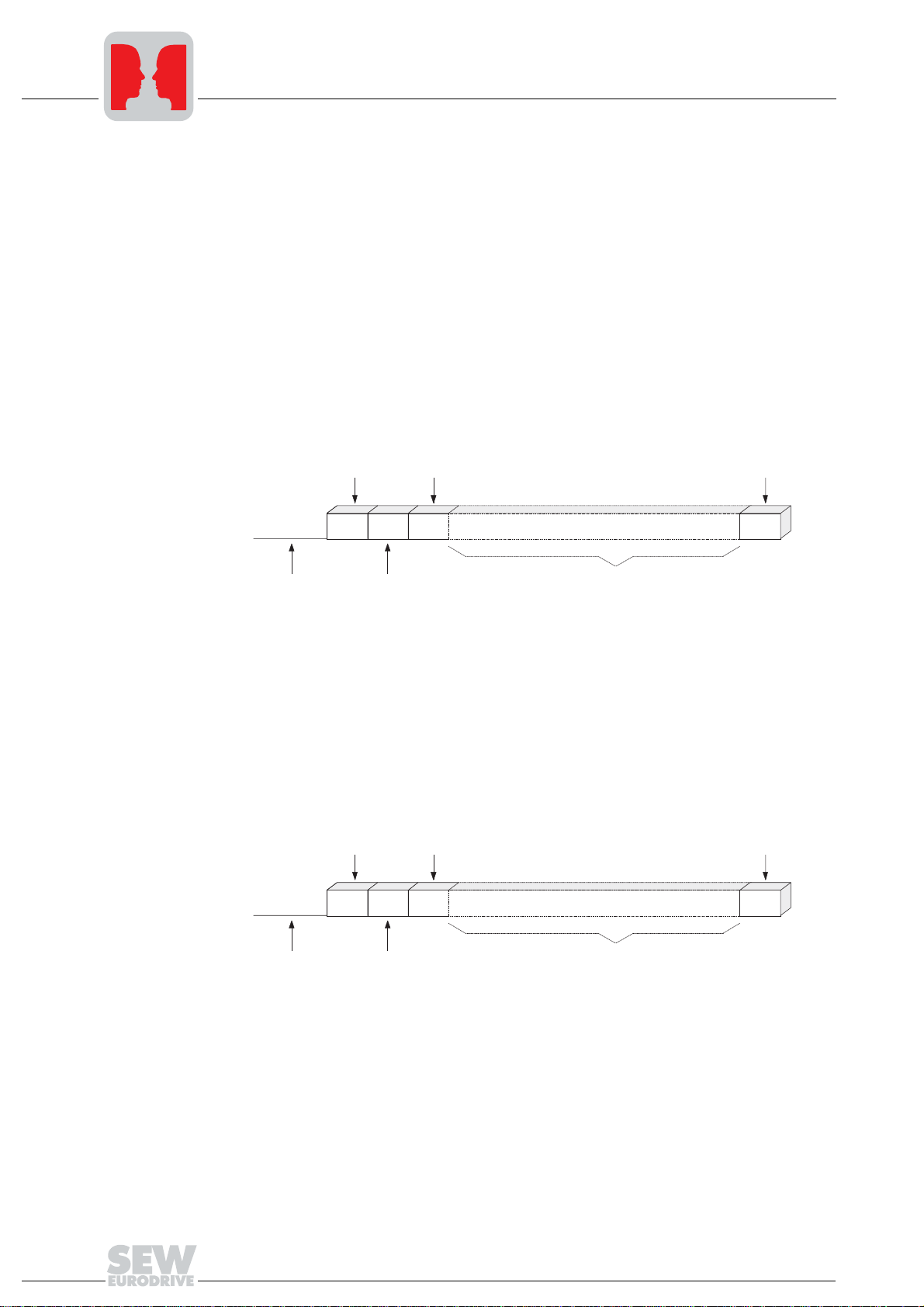
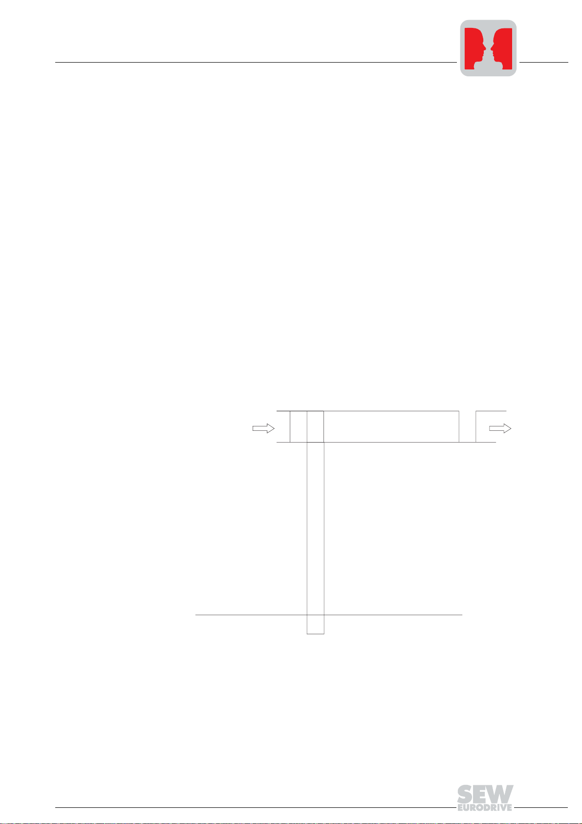
Fig. 12 shows the structure of the request telegram which the master sends to the
inverter. Each telegram starts with an idle time on the bus, referred to as the start pause,
followed by a start character. Different start characters are used so that it is possible to
clearly differentiate between request and response telegrams. The request telegram
starts with the start character SD1 = 02
, followed by the slave address and the PDU
hex
type.
Start delimiter 1
02 hex
....Idle...
Start pause Slave address Protocol data unit
SD1
ADR
PDU type
TYP
Block check character
PDU BCC
Response
telegram structure
Fig. 12: Structure of the request telegram
01485BEN
Fig. 13 shows the structure of the response telegram by means of which the inverter
(slave) responds to a request sent by the master. In turn, each response telegram starts
with a start pause, followed by a start character. The response telegram starts with the
start character SD2 = 1D
, followed by the slave address and the PDU type so that it
hex
is possible to clearly differentiate between request and response telegrams.
Start delimiter 2
02 hex
....Idle...
Start pause Slave address Protocol data unit
Fig. 13: Structure of the response telegram
SD2
ADR
PDU type
TYP
Block check character
PDU BCC
01487BEN
18
MOVIDRIVE® Serial Communication
Telegra ms
Start pause (idle) The master must observe a start pause of at least 3.44 ms before sending the start
character SD1 (02
telegram. This pause prevents the bit combination 02
user data, from being erroneously interpreted as the start character. As a result, the start
pause forms part of the start character. After it has received a valid request telegram,
the inverter waits for an idle time of at least 3.44 ms before sending back the response
telegram with the start character SD2 (1D
the start character of a response telegram as well. In case the transmission of a valid
request telegram is canceled by the master, a new request telegram cannot be sent until
at least two start pauses (6.88 ms) have elapsed.
) so that the inverter can definitively identify the start of a request
hex
). This enables the master to clearly identify
hex
, which may also occur in the
hex
4
Start character
(SD1 / SD2)
The start character and the preceding start pause detect the commencement and the
data direction of a new telegram. The following table shows the allocation of the start
character to the data direction.
SD1 02
SD2 1D
hex
hex
Request telegram Master → inverter
Response telegram Inverter → master
MOVIDRIVE
®
Serial Communication
19
4
Addressing and transmission process
4.2 Addressing and transmission process
Address byte
(ADR)
Individual
addressing
The address byte always specifies the slave address regardless of the data direction.
Therefore, the ADR character in a request telegram specifies the address of the inverter
which is to receive the request. In the opposite direction, the master can tell from which
inverter the response telegram was sent. Generally speaking, there is only one master
in the system. This means the master is not addressed. In addition to individual
addressing, the MOVILINK
®
protocol also offers further addressing options. The
following table shows the address areas and what they mean.
ADR Meaning
0 – 99 Individual addressing within an RS-485 bus
100 –
199
253
254 Universal address for peer-to-peer communication
255 Broadcast address
Group addressing (multicast)
Special case of group address 100: Means "Not assigned to any group", i.e. ineffective
plus®
Local address: Only effective in conjunction with IPOS
command. For communication within the unit.
as master and the MOVILINK
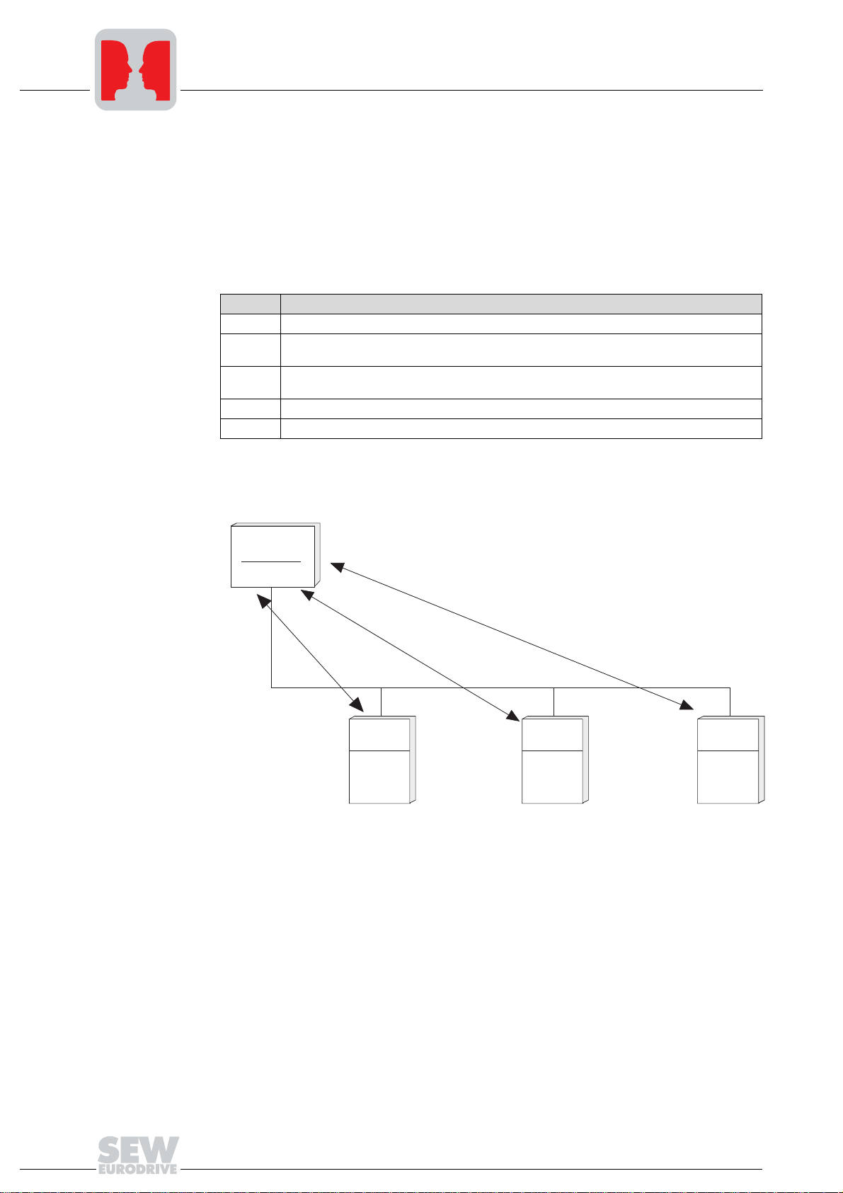
Each inverter can be addressed directly via addresses 0 – 99. Each request telegram
from the master is answered by a response telegram from the inverter.
Master
Request to ADR 1
Response from ADR 1
Request to ADR 3
Response from ADR 3
Request to ADR 12
Response from ADR 12
Slave SlaveSlave
Inverter Inverter
ADR: 1 ADR: 3
Fig. 14: Individual addressing via unit address 232/485
Inverter
ADR: 12
01488BEN
20
MOVIDRIVE® Serial Communication
Addressing and transmission process
4
Group addressing
(multicast)
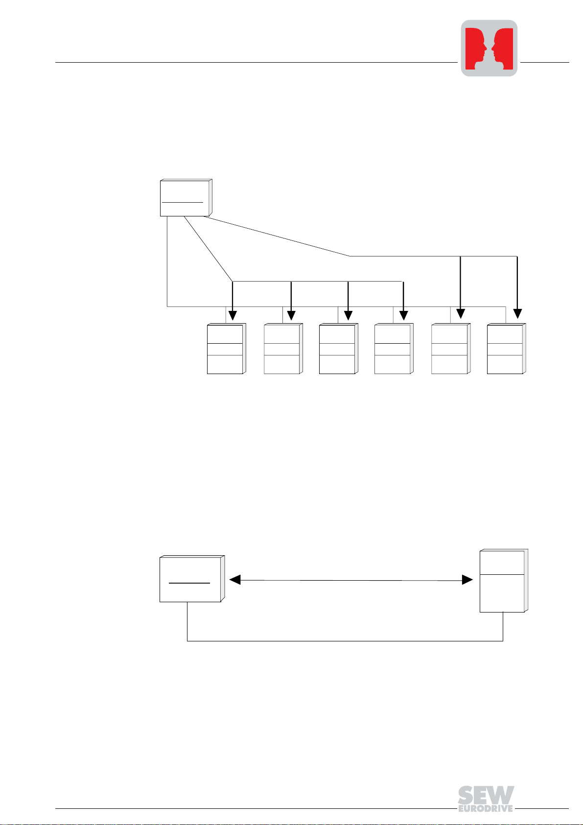
Each inverter possesses an adjustable group address in addtion to its individual
address. This setup enables the user to form groups with various stations and then
address the individual stations in a group simultaneously using the group address. No
response telegram is sent back to the master in the case of group addressing. This
means it is not possible to request data from the inverter. Also, there is no response
when data are written. You can create up to 99 groups.
Master
Request telegram to group adr. 102
Request telegram to group adr. 101
Slave Slave Slave Slave Slave Slave
Inveter
ADR: 1 ADR: 2 ADR: 3 ADR: 4 ADR: 5 ADR: 6
Group
adr.: 101
Inverter Inverter
Group
adr.: 101
Group
adr.: 101
Inverter
Group
adr.: 101
Inverter
Group
adr: 102
Inverter
Group
adr.: 102
Universal
addressing for
peer-to-peer
connection
Fig. 15: Addressing individual groups
01489BEN
Every inverter can be addressed via the universal address 254 regardless of the
individual address which has been set for it. The advantage of this method is that peerto-peer connections can be established via the RS-232 interface without necessarily
knowing the currently set individual address. Every inverter station is addressed with
this universal address, which means this method must not be used in multipoint
connections (e.g. RS-485 bus). Otherwise, there would be data collisions on the bus
because every inverter would send a response telegram after receiving the request
telegram.
Slave
Master
Fig. 16: Addressing in peer-to-peer connections with universal address 254
Request telegram via universal adr. 254
Response telegram from slave
Inverter
ADR: 1
01490BEN
MOVIDRIVE
®
Serial Communication
21
4
Addressing and transmission process
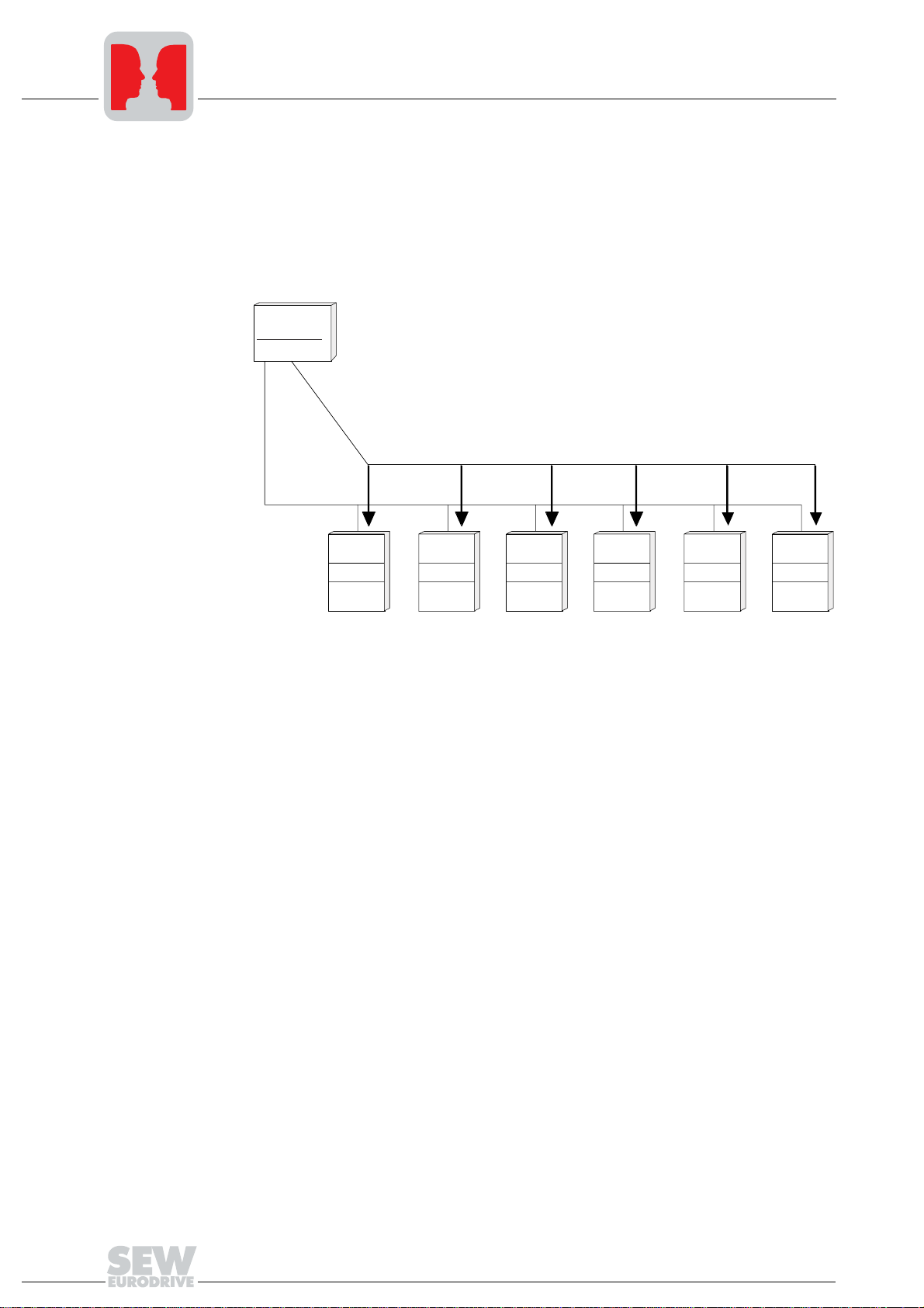
Broadcast address The broadcast address 255 permits a broadcast to all inverter stations. The request
telegram sent out by the master to broadcast address 255 is received by all inverters,
but they do not reply. Consequently, this addressing variant is predominantly used for
transferring setpoints. The master can send broadcast telegrams with a minimum time
interval of 25 ms, i.e. an idle time of at least 25 ms must be observed between the last
character sent in a request telegram (BCC) and the start of a new request telegram
(SD1).
Master
Request telegram to all slaves via broadcast adr. 255
Slave Slave Slave Slave Slave Slave
Inveter
Inverter Inverter
ADR: 1 ADR: 2 ADR: 3 ADR: 4 ADR: 5 ADR: 6
Group
adr.: 101
Group
adr.: 101
Fig. 17: Addressing individual groups
Group
adr.: 101
Inverter
Group
adr.: 101
Inverter
Group
adr: 102
Inverter
Group
adr.: 102
01491BEN
22
MOVIDRIVE® Serial Communication
Addressing and transmission process
Structure and
length of user
data
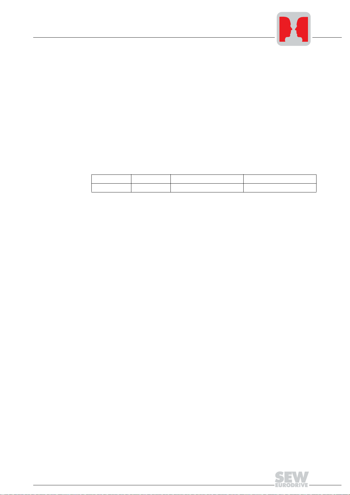
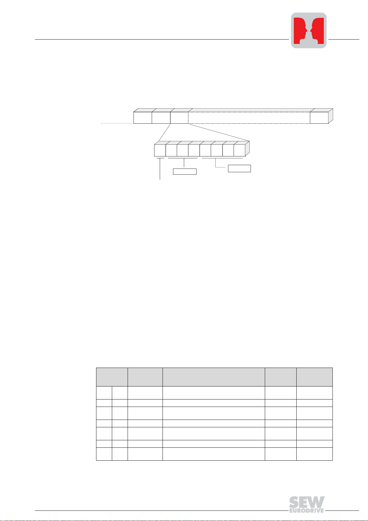
PDU type (TYP) The TYP byte describes the structure and the length of the user data which succeed it
(protocol data unit or PDU). Fig. 18 shows the structure of the type byte.
...Idle... SD1 ADR TYP PDU BCC
Bit: 7 6 5 4 3 2 1 0
4
reserved
transmission variant
0: cyclical
1: acyclical
PDU type
01492BEN
Fig. 18: Structure of the TYP byte
Bit 7 of the TYP byte is used to differentiate between cyclical or acyclical transmission
of user data. A request telegram with the cyclical transmission variant signals to the
inverter that the data sent by the master will be updated cyclically. Consequently, a
response monitoring function can be activated in the inverter. This means a timeout
response is triggered if the inverter does not receive a new cyclical request telegram
within an adjustable timeout delay.
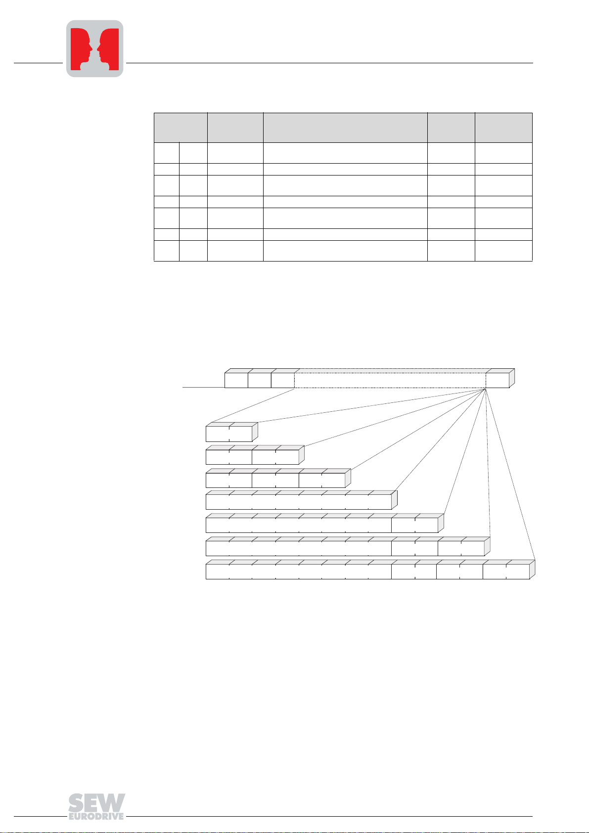
The following tables show the PDU types for cyclical and acyclical transmission.
However, not all PDU types are supported (depending on the type of inverter). The
special PDU types are not significant for general serial communication, and are thus not
included in the operator documentation. The length of the telegram depends on the
related PDU type and is always calculated as follows:
Telegram length = PDU length + 4.
CYCLICAL
transmission
MOVIDRIVE
PDU types in CYCLICAL transmission:
TYP byte PDU name Description
00
hex0dec
01
hex1dec
02
hex2dec
03
hex3dec
04
hex4dec
05
hex5dec
06
hex6dec
®
Serial Communication
PDU length
in bytes
PAR A M + 1 P D
1PD 1 process data word 2 6
PAR A M + 2 P D
2PD 2 process data words 4 8
PAR A M + 3 P D
3PD 3 process data words 6 10
PAR A M + 0 P D
8 bytes parameter channel + 1 process data
word
8 bytes parameter channel + 2 process data
words
8 bytes parameter channel +3 process data
words
8 bytes parameter channel without process
data
10 14
12 16
14 18
812
Tel egr am
length in
bytes
23
4
Addressing and transmission process
ACYCLICAL
transmission
PDU types in ACYCLICAL transmission:
TYP byte PDU name Description
80
81
82
83
84
85
86
hex
hex
hex
hex
hex
hex
hex
128
129
130
131
132
133
134
PAR A M + 1 P D
dec
dec
PAR A M + 2 P D
dec
dec
PAR A M + 3 P D
dec
dec
PAR A M + 0 P D
dec
1PD 1 process word 2 6
2PD 2 process data words 4 8
3PD 3 process data words 6 10
8 bytes parameter channel + 1 process data
word
8 bytes parameter channel + 2 process data
words
8 bytes parameter channel +3 process data
words
8 bytes parameter channel without process
data
The standard PDU types are made up of the MOVILINK
process data channel. Please refer to the MOVIDRIVE
®
Fieldbus Unit Profile for coding
PDU length
in bytes
10 14
12 16
14 18
812
®
parameter channel and a
Tel egra m
length in
bytes
of the parameter channel and the process data.
Fig. 19 shows the structure of a request telegram with the standard PDU types. The
corresponding response telegram has the same structure, except for the start character
SD2.
...Idle... SD1 ADR TYP PDU BCC
TYP 1/129
TYP 3/131
TYP 5/133
TYP 6/134
TYP 0/128
TYP 2/130
TYP 4/132
PD1
PD1
PD1
PD2
PD2
8 byte parameter channel
8 byte parameter channel
8 byte parameter channel
8 byte parameter channel
PD3
PD1
PD1
PD1
Fig. 19: Structure of the request telegram with the standard PDU types
PD2
PD2
PD3
01493BEN
24
MOVIDRIVE® Serial Communication
Block check
character BCC
Transmission
reliability
Addressing and transmission process
The transmission reliability of the MOVILINK
of character parity and block parity. This involves setting the parity bit for each character
of the telegram in such a way that the number of binary ones, including the parity bit, is
even. This means supplementing by the parity bit results in even character parity.
Block parity offers extra security. In this case, the telegram is supplemented by an
additional block check character (BCC). Each single bit of the block check character is
set in such a way that the telegram character is set to even parity again for all equivalent
information bits. Block parity is implemented in the program structure by an EXOR logic
operation of all telegram characters. The result is transmitted at the end of the telegram
in the BCC. The block check character itself is also safeguarded by means of even
character parity.
®
protocol is improved by the combination
4
Creating the block
check character
By way of example, the following table shows how the block check character is created
for a PDU type 5 cyclical telegram with 3 process data words. The EXOR logic operation
on the characters SD1 – PD3
results in the value 57
low
as the block check character
hex
BCC. This BCC is sent as the last character in the telegram. Once the receiver has
received the individual characters, it performs a character parity check. Following this
step, the block check character is created from the received characters SD1 – PD3
low
in accordance with the procedure below. The telegram has been correctly transmitted if
the calculated and received BCCs are identical and there is no character parity error.
Otherwise, a transmission error has occurred.
SD1: 02 hex
ADR: 01 hex
TYP: 05 hex
PD1 high: 00 hex
PD1 low: 06 hex
PD2 high: 3A hex
PD2 low: 98 hex
PD3 high: 01 hex
PD3 low: F4 hex
Stop
Parity
1
1
0
0
0
0
1
1
1
0
0
0
0
0
0
0
0
0
0
0
0
1
0
0
1
1
0
0
0
0
1
0
0
1
EXOR
0
EXOR
0
EXOR
0
EXOR
0
EXOR
1
EXOR
1
EXOR
0
EXOR
1
0
0
0
0
1
0
0
0
0
1
1
0
1
0
1
0
0
1
0
0
0
0
1
0
1
0
0
0
0
0
Start
0
1
1
0
0
0
0
1
0
MOVIDRIVE
calculated BCC:
Fig. 20: Creating the block check character BCC
®
Serial Communication
57 hex
1
1
01494BEN
1
1
0
1
0
1
0
25

4
Addressing and transmission process
Transmission
process
Character frame Each character in the MOVILINK
An asynchronous serial transmission procedure is used. This is supported by the UART
components of digital technology which are generally and commonly employed. This
means the MOVILINK
modules.
structure:
• 1 start bit
• 8 data bits
• 1 parity bit, supplementing to even parity
• 1 stop bit
Each transmitted character starts with a start bit (always logical 0). This is followed by 8
data bits and the parity bit. The parity bit is set in such a way that the number of logical
ones in the data bits, including the parity bit, is an even number. The character is
completed by a stop bit which is always set to the logical level 1. This level remains on
the transmission medium until a new start bit signals the start of a new character
transmission.
®
protocol can be implemented on almost all controls and master
11 bit character frame
®
protocol consists of 11 bits and has the following
01234567
Start
LSB MSB even
Fig. 21: Character frame
8 data bits
Stop
Parity
Start
01495BEN
26
MOVIDRIVE® Serial Communication

Addressing and transmission process
4
Transmission
rate and
transmission
mechanisms
Response delay
time of the master
Character delay
time
RS-485 timeout
delay of the
inverter
The transmission rate is 9600 baud. The communication link is monitored by the master
and the inverter themselves. The master monitors the response delay time; the inverter
monitors the receipt of cyclical request telegrams from the master.
A response delay time is generally programmed on the higher-level master system. The
response delay time is the time interval between the last character in the request
telegram (BCC) being sent and the start of the response telegram (SD2). The maximum
permitted response delay time is 50 ms. There has been a transmission error if the
inverter does not respond within this time. Check the interface cable or the coding of the
transmitted request telegram. For application reasons, the request telegram should now
be repeated again or the next inverter should be addressed.
The time gap between the transmission of the characters in a request telegram must be
shorter than the start pause. Otherwise, the inverter might interpret a character it
receives containing 02
hex
or 1D
as a start character.
hex
The maximum permitted time interval between two cyclical request telegrams is set in
MOVIDRIVE
®
using parameter P812 "RS485 timeout delay". A valid request telegram
must be received within this time interval. Otherwise, the inverter triggers an RS-485
timeout error and performs a defined error response.
The MOVIDRIVE
®
is kept in a safe status until the first request telegram is received once
the power is switched on or an error has been performed. "t" (= timeout active) appears
on the 7-segment display of an enabled inverter; the enable setting does not have any
effect. The enable takes effect once the telegram has been received and the drive starts
moving.
If the inverter is controlled via the RS-485 interface (P100 "Setpoint source" = RS-485 /
P101 "Control signal source" = RS-485) and an error response involving a warning has
been programmed, the process data most recently received take effect following an RS485 timeout and re-establishment of communication.
MOVIDRIVE
The RS-485 timeout acts jointly on both RS-485 interfaces. Timeout monitoring of the
second interface is ineffective when the DBG11A keypad is connected, because the
DBG11A continuously sends request telegrams to the inverter, thereby triggering the
timeout mechanism.
®
Serial Communication
27

4
Addressing and transmission process
Processing the
request/response
telegrams
The inverter only processes request telegrams which have been received without errors
and are correctly addressed. The following reception errors can be recognized:
• Parity error
• Character frame error
• Character delay time exceeded with request telegram
• Address incorrect
• PDU type incorrect
• BCC incorrect
• Response delay time elapsed (master)
• → Possible send repeat
• RS-485 timeout occurred (inverter)
• → Triggering timeout response
The inverter does not respond to incorrectly received request telegrams! These
reception errors have to be evaluated on the master end in order to safeguard data
transmission.
28
MOVIDRIVE® Serial Communication
 Loading...