

SEW-Eurodrive MOVIAXIS MXR81 Series Manual

Drive Technology \ Drive Automation \ System Integration \ Services
Manual MXR81..
*21219796_0414*
MXR81 Supply and Regenerative Module
MOVIAXIS® Multi-Axis Servo Inverter
Block-Shaped Regeneration
Edition 04/2014 21219796 / EN
SEW-EURODRIVE—Driving the world

Contents
Contents
1 General information .................................................................................................................. 6
1.1 Other applicable documentation .................................................................................... 6
1.2 Structure of safety notes ................................................................................................ 6
1.2.1 Meaning of signal words ................................................................................. 6
1.2.2 Structure of the section-related safety notes .................................................. 6
1.2.3 Structure of the embedded safety notes ......................................................... 7
1.3 Rights to claim under limited warranty ........................................................................... 7
1.4 Exclusion of liability ........................................................................................................ 7
1.5 Copyright ........................................................................................................................ 7
2 Safety notes ............................................................................................................................... 8
2.1 General information ........................................................................................................ 8
2.2 Target group ................................................................................................................... 8
2.3 Designated use .............................................................................................................. 9
2.3.1 Safety functions .............................................................................................. 9
2.4 Transportation and storage ............................................................................................ 9
2.5 Installation ...................................................................................................................... 9
2.6 Electrical connection .................................................................................................... 10
2.7 Safe disconnection ....................................................................................................... 10
2.8 Operation ..................................................................................................................... 10
2.9 Unit temperature .......................................................................................................... 11
3 Unit structure ........................................................................................................................... 12
3.1 Important information ................................................................................................... 12
3.2 Nameplate, type designation ........................................................................................ 12
3.3 Unit structure of supply and regenerative modules ...................................................... 14
3.4 Combinations of supply and regenerative modules with other units ............................ 14
3.5 Standard accessories ................................................................................................... 16
4 Installation................................................................................................................................ 18
4.1 Mechanical installation ................................................................................................. 18
4.2 UL-compliant installation .............................................................................................. 18
4.3 Installing/removing the supply and regenerative module ............................................. 19
4.4 Electrical installation ..................................................................................................... 19
4.5 Wiring diagrams ........................................................................................................... 21
21219796 / EN – 04/2014
3.2.1 Nameplate of supply and regenerative modules .......................................... 12
3.2.2 Type designation of supply and regenerative modules ................................ 13
3.3.1 Supply and regenerative module ................................................................. 14
3.5.1 Assignment table for standard accessories .................................................. 17
4.2.1 Permitted tightening torques ......................................................................... 19
4.4.1 Line contactor and cable cross sections ....................................................... 20
4.4.2 Connecting braking resistor and emergency braking resistor....................... 20
4.4.3 Operating braking resistor and emergency braking resistor ......................... 21
4.4.4 Permitted voltage supply systems ................................................................ 21
4.5.1 General information on the wiring diagrams ................................................. 21
4.5.2 Wiring the control electronics........................................................................ 22
Manual MXR81.. – MOVIAXIS® Multi-Axis Servo Inverter
3

Contents
4.5.3 Wiring of power connections ........................................................................ 23
4.5.4 Braking resistor connection........................................................................... 25
4.6 Terminal assignment .................................................................................................... 27
4.6.1 Terminal assignment of the supply and regenerative module ..................... 27
5 Startup ...................................................................................................................................... 30
5.1 General information ...................................................................................................... 30
5.1.1 Requirements................................................................................................ 30
5.2 Settings on the supply and regenerative module with CAN-based system bus ........... 30
5.2.1 Example ........................................................................................................ 31
5.3 Settings on the supply and regenerative module with EtherCAT® compatible system bus
XSE24A ........................................................................................................................ 33
5.4 Settings on the supply and regenerative module with EtherCAT® XFE24A fieldbus
interface ....................................................................................................................... 35
5.5 Starting up MXR81 with MOVITOOLS® MotionStudio .................................................. 36
5.5.1 Unit selection / opening the parameter tree .................................................. 36
5.5.2 Startup .......................................................................................................... 36
5.6 Switch-on/off sequence of the supply and regenerative module .................................. 38
5.6.1 Addendum to the diagram............................................................................. 40
5.6.2 Troubleshooting ............................................................................................ 40
5.7 Process data assignment for fieldbus operation .......................................................... 40
5.7.1 Controlling the supply and regenerative module........................................... 40
5.7.2 Process output data PO................................................................................ 42
5.7.3 Process input data PI.................................................................................... 44
5.8 Parameter description .................................................................................................. 46
5.8.1 Display values............................................................................................... 46
5.8.2 System data .................................................................................................. 49
5.8.3 Communication ............................................................................................. 50
5.8.4 Unit functions ................................................................................................ 53
6 Operation.................................................................................................................................. 54
6.1 General information ...................................................................................................... 54
6.2 Operating modes .......................................................................................................... 54
6.2.1 Normal operation .......................................................................................... 54
6.2.2 Test/emergency mode .................................................................................. 54
6.3 Operating displays and errors of the supply and regenerative module ....................... 55
6.3.1 Table of displays ........................................................................................... 55
6.3.2 Table of MXR errors...................................................................................... 57
7 Technical data.......................................................................................................................... 68
7.1 Technical data of supply and regenerative modules ................................................... 68
7.1.1 General technical data .................................................................................. 68
7.1.2 Power section of supply and regenerative module ...................................... 68
7.1.3 Control section of a supply and regenerative module .................................. 70
7.1.4 Bus communication....................................................................................... 71
7.2 Dimension sheet of supply and regenerative modules ............................................... 72
7.3 Hole pattern of supply and regenerative modules ....................................................... 73
7.4 Technical data of additional components ..................................................................... 74
21219796 / EN – 04/2014
Manual MXR81.. – MOVIAXIS® Multi-Axis Servo Inverter
4

Contents
7.4.1 NF.. line filters for 3-phase systems.............................................................. 74
7.4.2 ND.. line choke.............................................................................................. 76
7.4.3 Braking resistors BW..., BW...-01, BW...-T, BW...-P..................................... 77
8 Project planning ...................................................................................................................... 80
8.1 Components for EMC-compliant installation ................................................................ 80
8.1.1 Interference immunity ................................................................................... 80
8.1.2 Interference emission.................................................................................... 80
8.2 Project planning for supply and regenerative modules ............................................... 80
8.3 Project planning for axis modules and motors ............................................................. 81
8.4 Line contactors and line fuses ...................................................................................... 81
8.4.1 Line contactor ............................................................................................... 81
8.4.2 Line fuse types.............................................................................................. 81
8.5 Projecting the power supply ......................................................................................... 81
8.5.1 50 kW variant ................................................................................................ 84
8.5.2 75 kW variant ................................................................................................ 85
8.5.3 Project planning example.............................................................................. 86
8.5.4 Output power with low line voltage ............................................................... 86
8.6 Projecting the power supply taking account of simultaneities ...................................... 86
8.6.1 Introduction ................................................................................................... 86
8.6.2 Switching sequence between enabled and inhibited output stage ............... 86
8.7 Projecting the cable cross sections .............................................................................. 86
8.7.1 Special regulations........................................................................................ 86
8.7.2 Power cable length ....................................................................................... 86
8.7.3 Cable cross sections and fusing ................................................................... 86
8.7.4 Supply and regenerative modules ............................................................... 86
8.8 Project planning for emergency braking resistor and braking resistor ......................... 86
8.8.1 Notes regarding emergency braking resistors .............................................. 86
8.8.2 Selecting the emergency braking resistor..................................................... 86
8.8.3 Notes regarding braking resistors ................................................................. 86
8.8.4 Selecting the braking resistor........................................................................ 86
8.9 Overload capacity ........................................................................................................ 86
8.10 Selecting the 24 V supply ............................................................................................. 86
8.11 Checklist for project planning ....................................................................................... 86
8.11.1 Checklist ....................................................................................................... 86
Index ....................................................................................................................................... 100
21219796 / EN – 04/2014
Manual MXR81.. – MOVIAXIS® Multi-Axis Servo Inverter
5
General information
Other applicable documentation
1
1 General information
1.1 Other applicable documentation
This manual describes the specific features of the MXR supply and regenerative module.
For any other information and functions of MOVIAXIS, please refer to the
• "MOVIAXIS® Multi-Axis Servo Inverter" operating instructions,
• MOVIAXIS® Multi-Axis Servo Inverter" system manual.
1.2 Structure of safety notes
1.2.1 Meaning of signal words
The following table shows the grading and meaning of the signal words for safety
notes, damage to property warnings, and other notes.
Signal word Meaning Consequences if disregarded
DANGER Imminent hazard Severe or fatal injuries
WARNING Possible dangerous situation Severe or fatal injuries
CAUTION Possible dangerous situation Minor injuries
NOTICE Possible damage to property Damage to the drive system or its
INFORMATION Useful information or tip:
environment
Simplifies handling of the
drive system.
1.2.2 Structure of the section-related safety notes
Section safety notes do not apply to a specific action but to several actions pertaining
to one subject. The symbols used either indicate a general hazard or a specific hazard.
This is the formal structure of a section safety note:
SIGNAL WORD
Type and source of hazard.
Possible consequence(s) if disregarded.
• Measure(s) to prevent the hazard.
21219796 / EN – 04/2014
Manual MXR81.. – MOVIAXIS® Multi-Axis Servo Inverter
6

1.2.3 Structure of the embedded safety notes
Embedded safety notes are directly integrated in the instructions just before the description of the dangerous action.
This is the formal structure of an embedded safety note:
• SIGNAL WORD Type and source of hazard.
Possible consequence(s) if disregarded.
– Measure(s) to prevent the hazard.
1.3 Rights to claim under limited warranty
General information
Rights to claim under limited warranty
1
A requirement of fault-free operation and fulfillment of any rights to claim under limited
warranty is that you adhere to the information in this manual as well as in the
"MOVIAXIS® Multi-Axis Servo Inverter" operating instructions. Therefore, read the
manual and the operating instructions before you start working with the unit.
Make sure that the manual and the operating instructions are available to persons responsible for the system and its operation as well as to persons who work independently on the unit. You must also ensure that the documentation is legible.
1.4 Exclusion of liability
You must comply with the information contained in this manual and in the "MOVIAXIS
Multi-Axis Servo Inverter" operating instructions to ensure safe operation of the MXR
supply and regenerative module in conjunction with the MOVIAXIS® multi-axis servo
inverter and to achieve the specified product characteristics and performance requirements. SEW‑EURODRIVE assumes no liability for injury to persons or damage to
equipment or property resulting from non-observance of the manual and the operating
instructions. In such cases, any liability for defects is excluded.
1.5 Copyright
© 2014 - SEW‑EURODRIVE. All rights reserved.
Copyright law prohibits the unauthorized duplication, modification, distribution, and
use of this document, in whole or in part.
®
21219796 / EN – 04/2014
Manual MXR81.. – MOVIAXIS® Multi-Axis Servo Inverter
7

Safety notes
General information
2
2 Safety notes
The following basic safety notes must be read carefully to prevent injury to persons
and damage to property. The user must ensure that the basic safety notes are read
and observed. Make sure that persons responsible for the plant and its operation, as
well as persons who work independently on the unit, have read through the operating
instructions and manual carefully and understood them. If you are unclear about any
of the information in this documentation, or if you require further information, please
contact SEW‑EURODRIVE.
INFORMATION
Observe the information about the other modules of a MOVIAXIS® axis system in the
"MOVIAXIS® MX Multi-Axis Servo Inverter" operating instructions when installing,
starting up, and operating the MXR regenerative supply module.
2.1 General information
Never install damaged products or put them into operation. Submit a complaint to the
shipping company immediately in the event of damage.
During operation, multi-axis servo inverters can have live, bare and movable or rotating parts as well as hot surfaces, depending on their degree of protection.
Removing required covers without authorization, improper use or incorrect installation
and operation may result in severe injury to persons, or damage to machinery.
Refer to the documentation for more information.
2.2 Target group
Only qualified electricians are authorized to install, start up or service the units or
correct unit faults (observing IEC 60364 or CENELEC HD 384 or DIN VDE 0100 and
IEC 60664 or DIN VDE 0110 as well as national accident prevention guidelines).
Qualified electricians in the context of these basic safety notes are all persons familiar
with installation, assembly, startup and operation of the product who possess the necessary qualifications.
All persons involved in any other work, such as transportation, storage, operation and
disposal, must be trained appropriately.
Manual MXR81.. – MOVIAXIS® Multi-Axis Servo Inverter
8
21219796 / EN – 04/2014

2.3 Designated use
Safety notes
Designated use
2
The MXR supply and regenerative module is designed for integration in the device
network of the MOVIAXIS® MX multi-axis servo inverter.
MOVIAXIS® MX multi-axis servo inverters are units for use in industrial and commercial systems to operate permanent-field synchronous AC motors and asynchronous
AC motors with encoder feedback. The motors must be suitable for operation with servo inverters. Do not connect other loads to the units without prior consultation of the
manufacturer.
MOVIAXIS® MX multi-axis servo inverters are intended for use in metal control cabinets. These metal control cabinets represent the necessary degree of protection for
the application as well as the grounding over a large area required for EMC purposes.
When installed in machines, startup of the multi-axis servo inverters (i.e. start of designated operation) is prohibited until it is determined that the machine meets the requirements stipulated in Directive 2006/42/EC (Machinery Directive); observe EN 60204.
Startup (i.e. the start of designated use) is only permitted under observance of the
EMC directive (2004/108/EC).
Multi-axis servo inverters comply with the low voltage directive 2006/95/EC. The
harmonized standards of the EN 61800-5-1/DIN VDE T105 series in connection with
EN 60439-1/VDE 0660 part 500 and EN 60146/VDE 0558 are applied to these multiaxis servo inverters.
Adhere to the technical data and information on the connection requirements as provided on the nameplate and in the documentation.
2.3.1 Safety functions
MOVIAXIS® multi-axis servo inverters may not take on safety functions without a higher-level safety system. Use higher-level safety systems to ensure protection of equipment and personnel.
For safety applications, refer to the information in the following publication:
• "MOVIAXIS® Multi-Axis Servo Inverters – Functional Safety".
2.4 Transportation and storage
Observe the notes on transportation, storage and proper handling. Observe the climatic conditions as stated in the chapter "General technical data".
2.5 Installation
21219796 / EN – 04/2014
The units must be installed and cooled according to the regulations and specifications
in the corresponding documentation.
Protect multi-axis servo inverters from excessive strain. Ensure that elements are not
deformed and/or insulation spaces are maintained, particularly during transportation.
Avoid contact with electronic elements and contacts.
Multi-axis servo inverters contain components that can be damaged by electrostatic
energy and could be destroyed in case of improper handling. Prevent mechanical
damage or destruction of electric components as this may pose a health risk.
The following applications are prohibited unless explicitly permitted:
• Use in potentially explosive atmospheres.
Manual MXR81.. – MOVIAXIS® Multi-Axis Servo Inverter
9

Safety notes
Electrical connection
2
• Use in areas exposed to harmful oils, acids, gases, vapors, dust, radiation, etc.
• Use in non-stationary applications which are subject to mechanical vibration and
2.6 Electrical connection
impact loads in excess of the requirements in EN 61800-5-1.
Observe the applicable national accident prevention guidelines, such as GBV A3,
when working on live components of multi-axis servo inverters.
Perform electrical installation according to the pertinent regulations (e.g. cable cross
sections, fusing, protective conductor connection). For any additional information, refer
to the applicable documentation.
You will find notes on EMC-compliant installation, such as shielding, grounding, arrangement of filters and routing of lines, in the documentation of the multi-axis servo
inverter. Always observe these notes even for multi-axis servo inverters bearing the
CE marking. The manufacturer of the system or machine is responsible for maintaining the limits established by EMC legislation.
Protective measures and protection devices must comply with the regulations in force,
such as EN 60204 or EN 61800-5-1.
Required preventive measure: Grounding the unit.
Cables may only be connected and switches may only be operated in a de-energized
state.
2.7 Safe disconnection
The unit meets all requirements for reliable isolation of power and electronics connections in accordance with EN 61800-5-1. All connected circuits must also meet the requirements for safe disconnection to ensure reliable isolation.
2.8 Operation
Systems with integrated multi-axis servo inverters might have to be equipped with additional monitoring and protection devices so they comply with applicable safety guidelines, such as the law governing technical equipment, accident prevention regulations,
etc. Changes to the drive inverters using the software are permitted.
Do not touch live components or power connections immediately after disconnecting
the multi-axis servo inverters from the supply voltage because there may still be some
charged capacitors. Note the respective labels on the multi-axis servo inverter.
Cables may only be connected and switches may only be operated in a de-energized
state.
Keep all covers and doors closed during operation.
The unit may still be live and connected to the power supply even if the operation
LEDs and other display elements are no longer illuminated.
Mechanical blocking or internal safety functions of the unit can cause a motor standstill. Eliminating the cause of the problem or performing a reset may result in the drive
re-starting automatically. If this is not permitted for the driven machine for safety reasons, disconnect the unit from the supply system before correcting the fault.
21219796 / EN – 04/2014
10
Manual MXR81.. – MOVIAXIS® Multi-Axis Servo Inverter

2.9 Unit temperature
Safety notes
Unit temperature
2
MOVIAXIS® multi-axis servo inverters are usually operated with braking resistors. The
braking resistors can be installed in the housing of the supply modules.
The braking resistors can reach a surface temperature between 70 °C and 250 °C.
Never touch the housings of MOVIAXIS® modules or the braking resistors during operation or in the cool down phase after the unit has been switched off.
21219796 / EN – 04/2014
Manual MXR81.. – MOVIAXIS® Multi-Axis Servo Inverter
11
Unit structure
[1]
[2]
[3]
[2]
I
[3] III
Important information
3
3 Unit structure
3.1 Important information
Protective measures and protection devices must comply with the regulations in
force.
INFORMATION
Adhere to the specific operating instructions when installing and starting up the motor
and the brake.
WARNING
The following "unit structure" illustrations represent the units without the provided
protection covers and touch guards. The protection cover protects the area of the
line and braking resistor connections; the touch guard protects the area of the DC
link.
Uncovered power connections.
• Never start the unit without protective covers and touch guards.
• Install protective covers and touch guards as instructed.
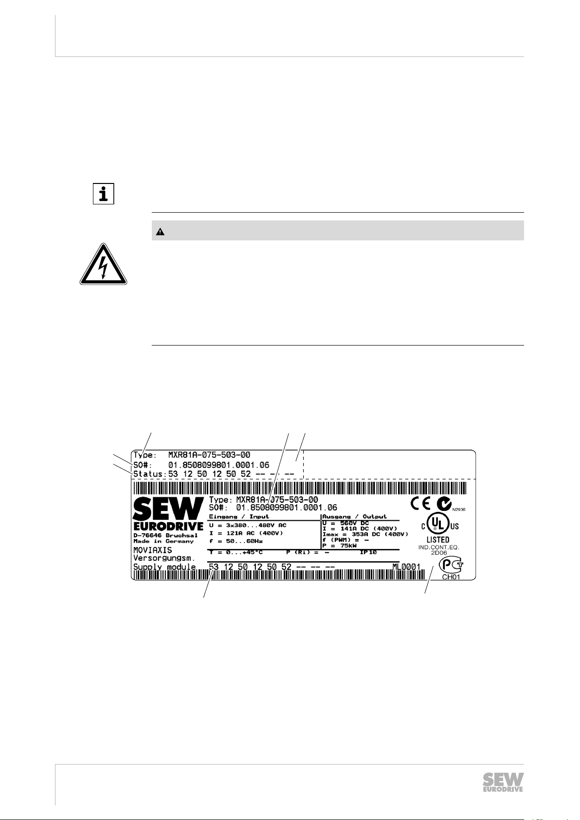
3.2 Nameplate, type designation
3.2.1 Nameplate of supply and regenerative modules
4325009163
I Part "I" of the nameplate: Located on the upper
III Part "III" of the nameplate: Located on the side
fastening plate of the module
of the module housing
[1] Type designation
[2] Production number
[3] Status
12
21219796 / EN – 04/2014
Manual MXR81.. – MOVIAXIS® Multi-Axis Servo Inverter
3.2.2 Type designation of supply and regenerative modules
Example: MXR81A-075-503-00
Product name MX MOVIAXIS
Unit type R Supply and regenerative module
Unit variant 81 • 80 = Sine-shaped regeneration
• 81 = Block-shaped regeneration
Development status A Development status of the unit series
Power 075 • 050 = 50 kW
• 075 = 75 kW
Supply voltage 50 U = AC 400 – 480 V
Connection type 3 3-phase
Design 00 • 00 = Standard design
• xx = Special design
Unit structure
Nameplate, type designation
®
3
Type designations of supply and regenerative modules
• MXR81A-050-503-00
• MXR81A-075-503-00
21219796 / EN – 04/2014
Manual MXR81.. – MOVIAXIS® Multi-Axis Servo Inverter
13
Unit structure
X9a
X9b
B
A
[1]
[4]
[10]
[3]
[15]
C
[2]
[5]
[6]
[8]
[7]
[9]
[11]
[13]
[12]
[14]
Unit structure of supply and regenerative modules
3
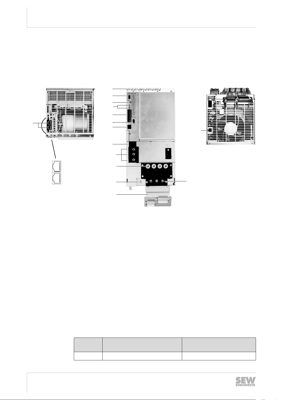
3.3 Unit structure of supply and regenerative modules
The following figure shows the unit without protective cover.
3.3.1 Supply and regenerative module
A View from top B View from front C View from bottom
[1] Signaling bus
X9a: Input, green connector on cable
X9b: Output, red connector on cable
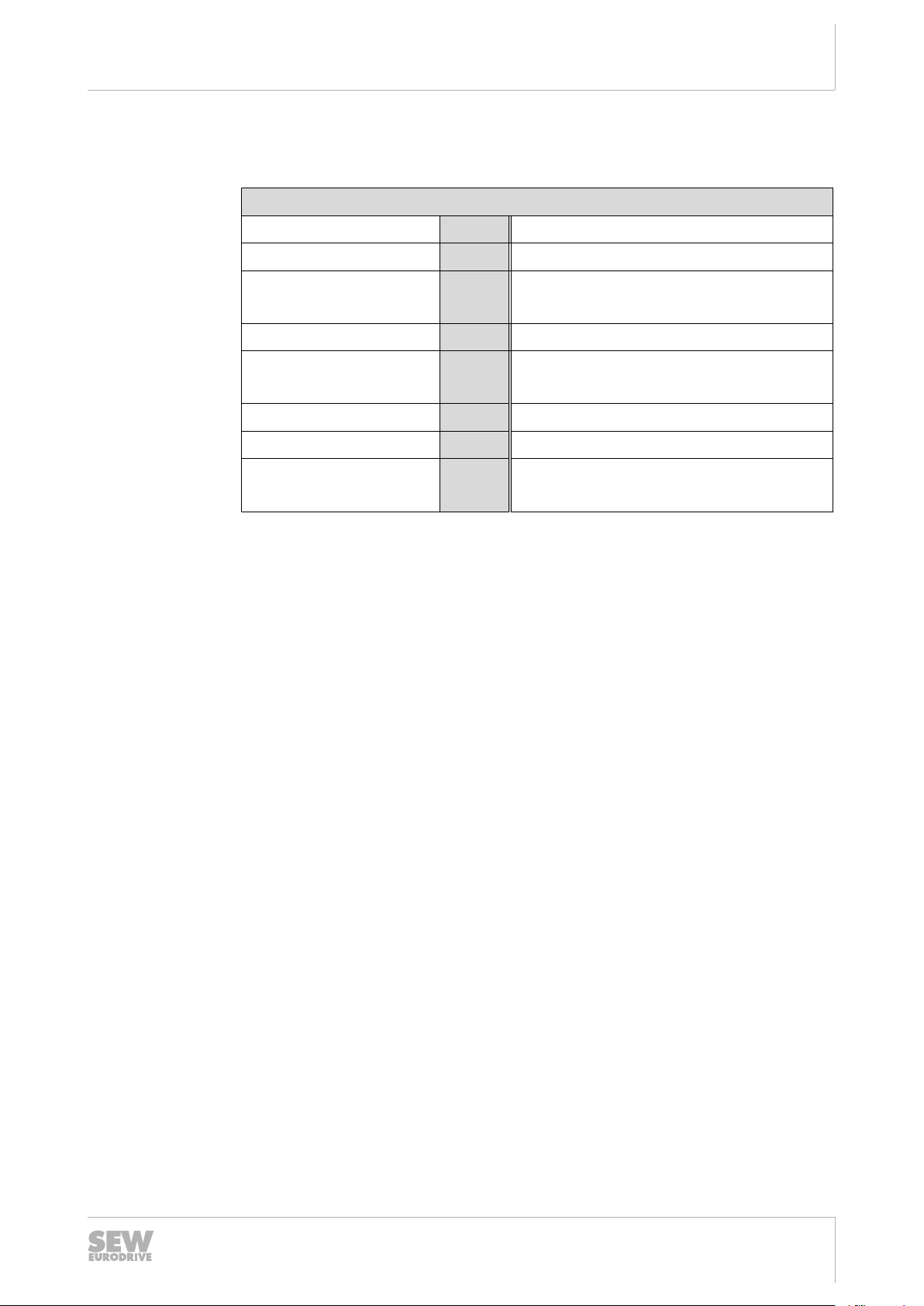
3.4 Combinations of supply and regenerative modules with other units
Unit Possible combination with
MXP – –
[2] Electronics shield terminals [15] X19: Enable contact for line con-
[3] X12: CAN system bus
[4] S1, S2: DIP switches
[5] S3, S4: Address switch
[6] X10: Digital inputs (pins 1 – 6)
X11: Digital outputs (pins 7 – 11)
[7] X17: CAN2 bus
[8] 2 x 7-segment display
[9] X5a, X5b: 24 V voltage supply
[10] X4: DC link connection
[11] X1: Line connection
[12] Housing grounding point
[13] Power shield clamp
[14] X3: Braking resistor connection
tactor
Quantity
MXR81
4324727563
21219796 / EN – 04/2014
14
Manual MXR81.. – MOVIAXIS® Multi-Axis Servo Inverter

Unit structure
Combinations of supply and regenerative modules with other units
3
Unit Possible combination with
MXR81
MXA X 8
MXC – –
MXB –
MXS – –
MXZ –
MXM X 1
1) Please consult SEW‑EURODRIVE
1)
1)
Quantity
1)
–
1)
–
21219796 / EN – 04/2014
Manual MXR81.. – MOVIAXIS® Multi-Axis Servo Inverter
15
Unit structure
[1]
[2]
[3]
[4]
[5]
[6]
[7]
[8]
[9]
[10]
[12]
[15]
[30]
[16]
[11]
[18]
[19]
[20]
[21]
[22]
[24]
[25]
[26]
[27]
[17]
[23]
[29]
[28]
[13]
[14]
Standard accessories
3
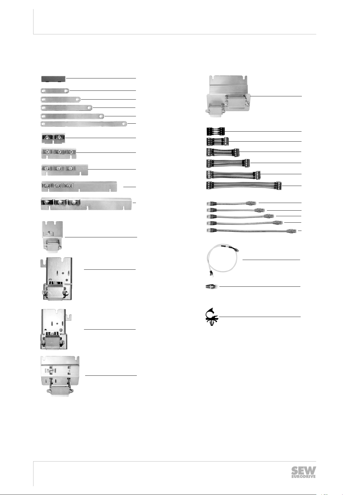
3.5 Standard accessories
Standard accessories are included with the basic unit at delivery.
The mating connectors for all connectors are installed at the factory. An exception are
4324740363
D-sub connectors, which are supplied without mating connector.
16
Manual MXR81.. – MOVIAXIS® Multi-Axis Servo Inverter
21219796 / EN – 04/2014
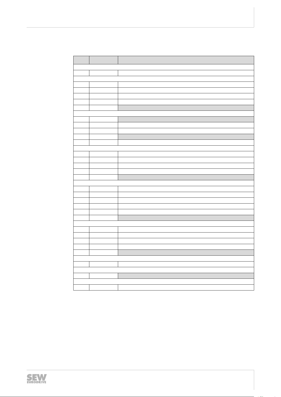
3.5.1 Assignment table for standard accessories
No. Dimension
Touch guard
[1] –
DC link connection
[2] 76 mm –
[3] 106 mm –
[4] 136 mm –
[5] 160 mm –
[6] 226 mm 3x
Electronics shield terminal
[7] 60 mm 1x
[8] 90 mm –
[9] 120 mm –
[10] 150 mm 1x
[11] 210 mm –
Power shield clamp
[12] 60 mm –
[13] 60 mm
[14] 60 mm
[15] 105 mm –
[16] 105 mm 1x
24 V supply cable
[17] 40 mm –
[18] 50 mm –
[19] 80 mm –
[20] 110 mm –
[21] 140 mm –
[22] 200 mm 1x
Signal bus connection cable (suitable for CAN/EtherCAT®-compatible system bus)
[23] 200 mm –
[24] 230 mm –
[25] 260 mm –
[26] 290 mm –
[27] 350 mm 1x
Connection cable between CAN and master module
[28] 520 mm –
CAN terminating resistor
[29] 1x
Cable terminals
[30] –
1) Length of the cables: Length of the bulk cables without connectors
2) Terminal with short support, 60 mm wide
3) Terminal with long support, 60 mm wide
1)
2)
3)
MXR81
–
–
Unit structure
Standard accessories
3
21219796 / EN – 04/2014
Manual MXR81.. – MOVIAXIS® Multi-Axis Servo Inverter
17
Installation
Mechanical installation
4
4 Installation
4.1 Mechanical installation
CAUTION
Never install defective or damaged modules of the MOVIAXIS® MX multi-axis servo
inverter as they can result in injuries or damage parts of the production system.
• Before installing modules of the MOVIAXIS® MX multi-axis servo inverter, check
CAUTION
Danger of burns on the surface of line chokes.
• Do not touch the hot surface of line chokes. Surface temperatures can exceed
• Let the chokes cool down before touching them.
them for external damage. Replace any damaged modules.
100 °C during and after operation.
NOTICE
The mounting plate in the control cabinet must be conductive over a large area for
the mounting surface of the inverter system (metallically pure, good conductivity).
EMC compliant installation of the MOVIAXIS® MX multi-axis servo inverter can only
be accomplished with a mounting plate that is conductive over a large area.
4.2 UL-compliant installation
• Check to see that the delivery is complete.
Note the following information for UL-compliant installation:
• Use only copper conductors with a temperature range of 60 / 75 °C as connection
cable.
• Observe the permitted tightening torques (→ 2 19) of the MOVIAXIS® power terminals.
NOTICE
Possible damage to the supply and regenerative module.
• Use only the stipulated connection elements and adhere to the specified tightening torques. Else, excessive heat can develop which would damage the supply
and regenerative module.
18
Manual MXR81.. – MOVIAXIS® Multi-Axis Servo Inverter
• MOVIAXIS® MX multi-axis servo inverters are suitable for operation in voltage networks with earthed star point (TN and TT networks), a maximum line current of
42000 A and a maximum line voltage of AC 500 V.
• Maximum permitted value of the line fuse:
21219796 / EN – 04/2014

Installing/removing the supply and regenerative module
MXR81 supply and regenerative module
Installation
4
P
N
I
N
Line fuse 100 A 150 A
• Select the cross section of the supply system lead in such a way that it matches
the nominal unit current, see chapter "Technical Data".
• Comply with the country-specific installation regulations in addition to the above
notes.
• The plug-in connections of the 24 V supply are limited to 10 A.
INFORMATION
Observe the technical data for operation of the required line filters (→ 2 74) and line
chokes (→ 2 76).
4.2.1 Permitted tightening torques
Please observe the document "Information regarding UL" on the SEW website
www.sew‑eurodrive.com.
The permitted tightening torques are:
• Line connection X1: 6.0 – 10.0 Nm
• Emergency braking resistor/braking resistor terminals: 3.0 – 4.0 Nm
• X10, X11 signal terminals for all units: 0.5 – 0.6 Nm
• DC link connection X4: 3.0 – 4.0 Nm
• Terminals for 24 V voltage supply: 0.5 – 0.6 Nm
50 kW 75 kW
80 A 121 A
4.3 Installing/removing the supply and regenerative module
Refer to the "MOVIAXIS® MX Multi-Axis Servo Inverter" operating instructions for a description of how to install a module in an axis system and how to remove it. Adhere to
these instructions when installing/removing a module.
4.4 Electrical installation
WARNING
Dangerous voltage levels may still be present inside the unit and at the terminal
strips up to 10 minutes after the complete axis system has been disconnected from
the supply system.
Severe or fatal injuries from electric shock.
• Disconnect the axis system from the supply system and wait 10 minutes before
removing the protective covers.
• After maintenance work, do not operate the axis system unless you have replaced the protective cover and the touch guard. Without protective cover, the
21219796 / EN – 04/2014
unit only has degree of protection IP00.
Manual MXR81.. – MOVIAXIS® Multi-Axis Servo Inverter
19
Installation
Electrical installation
4
WARNING
A leakage current > 3.5 mA can occur during operation of the MOVIAXIS® MX multiaxis servo inverter.
Severe or fatal injuries from electric shock.
• If the supply system lead is < 10 mm2, route a second PE conductor with the
same cross section as the supply system lead via separate terminals. Instead,
you can use a PE conductor with a copper cross section of ≥ 10 mm2 or aluminum ≥ 16 mm2.
• With an incoming supply line ≥ 10 mm2, it is sufficient to install a PE conductor
with a copper cross section ≥ 10 mm2 or aluminum ≥ 16 mm2.
• If an earth leakage circuit breaker can be used for protection against direct and
indirect contact, it must be universal current sensitive (RCD type B).
INFORMATION
Safe disconnection.
The unit meets all requirements for safe disconnection of power and electronics connections in accordance with EN 61800-5-1. The connected signal circuits have to
meet the requirements according to SELV (Safe Extremly Low Voltage) or PELV
(Protective Extra Low Voltage) to ensure safe disconnection. The installation must
meet the requirements for safe disconnection.
4.4.1 Line contactor and cable cross sections
4.4.2 Connecting braking resistor and emergency braking resistor
NOTICE
• Use a line contactor in utilization category AC-3 (IEC 158-1) or better. For information on the current carrying capacity, refer to chapter "Control section
of MXR supply and regenerative module" (→ 2 70).
• Line cable: Cross section according to nominal input current I
load.
NOTICE
When using a braking resistor, observe the notes in chapter "Project Planning".
• SEW‑EURODRIVE recommends to connect the braking resistor as shown in chapter "Wiring diagrams". Install switch F16 close to the unit network. If you use an unshielded cable for connecting switch F16 with the supply and regenerative module,
keep the length as short as possible. Preferably use a shielded power cable or
twisted individual lines as connection cable to the braking resistor. The cross section must be selected depending on the nominal current of the braking resistor/
emergency braking resistor.
at nominal
line
21219796 / EN – 04/2014
20
Manual MXR81.. – MOVIAXIS® Multi-Axis Servo Inverter
• Protect the braking resistor with an overload relay. Set the tripping current according to the technical data of the braking resistor, see "MOVIAXIS® MX MultiAxis Servo Inverter" operating instructions.
• Observe the notes in chapter "UL compliant installation" (→ 2 18).
4.4.3 Operating braking resistor and emergency braking resistor
• The connection lead to the braking resistor/emergency braking resistor carries a
high DC voltage of up to 970 V during nominal operation.
WARNING
The surfaces of the braking resistors/emergency braking resistors reach temperatures of up to 250 °C when the braking resistors are subject to a load of PN.
Risk of burns and fire.
• Choose a suitable installation location. Braking resistors/emergency braking resistors are usually mounted on the control cabinet.
• Do not touch any braking resistor.
Installation
Wiring diagrams
4
4.4.4 Permitted voltage supply systems
• MOVIAXIS® is intended for operation on voltage supply systems with a directly
grounded star point (TN and TT power systems).
• Operation on voltage supply systems with a non-grounded star point (for example
IT power systems) is not permitted.
• Autonomous power systems are not permitted.
An autonomous power system has no connection to the public grid.
4.5 Wiring diagrams
4.5.1 General information on the wiring diagrams
INFORMATION
The technical data of the power and control electronics connections are described in
chapter "Technical Data" in this manual and in the "MOVIAXIS® MX Multi-Axis Servo
Inverter" operating instructions.
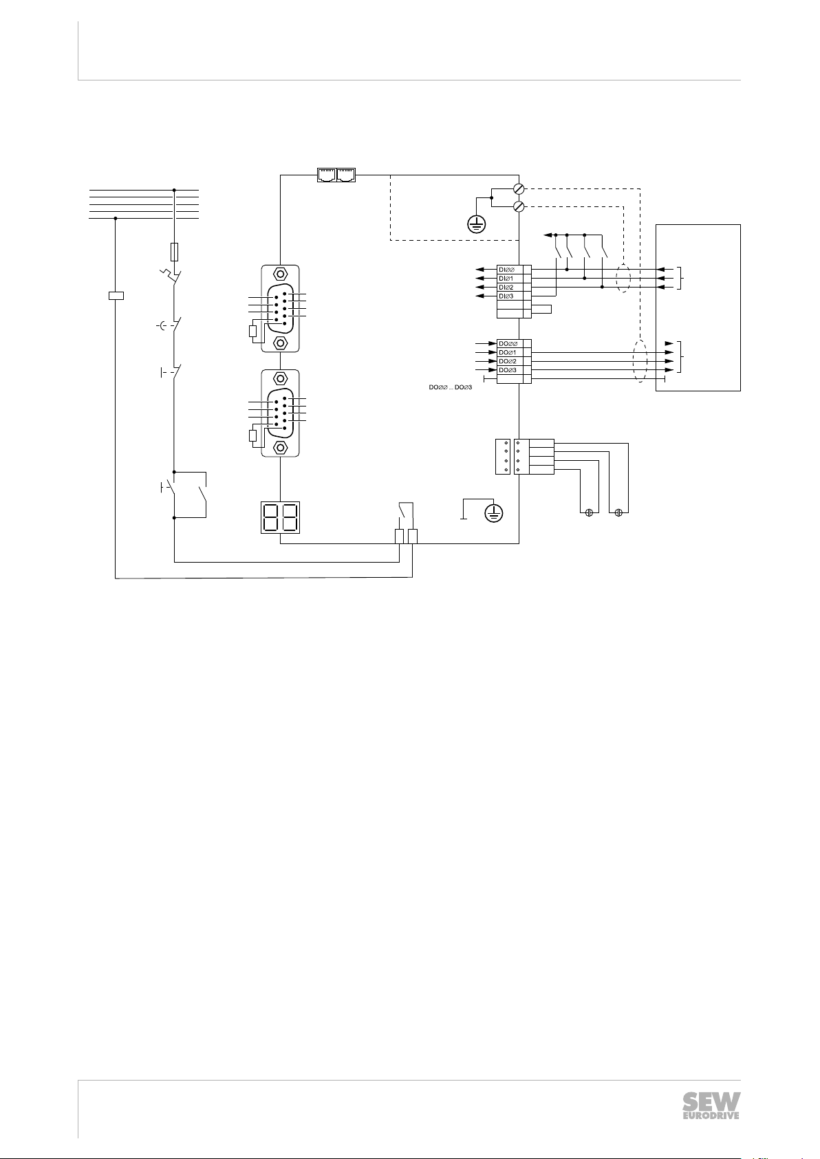
• All units within the axis system have to be connected to each other via the DC link
bus connection (PE, + Uz, –Uz), the 24 V voltage supply (X5a, X5b) and the signaling bus (X9a, X9b).
• The line contactor "K11" must be installed between the supply system and the line
filter.
21219796 / EN – 04/2014
Manual MXR81.. – MOVIAXIS® Multi-Axis Servo Inverter
21
Installation
X9a X9b
X10X12
X17
Input
sign. bus
Output
signaling bus
1
6
7
8
9
2
3
4
5
not connected
CAN L
DGND
CAN L
DGND
CAN H
CAN H
Device-internal
bus terminating
resistor
1
6
7
8
9
2
3
4
5
not connected
CAN L
DGND
CAN L
DGND
CAN H
CAN H
Device-internal
bus terminating
resistor
Electronics
shield terminals
Higher-level
controller/PLC
1
2
3
4
DCOM 5
DGND 6
Output stage enable**
+24V
E
Enable/charge
RESET or test/emergency mode
Line contactor feedback***
Ready
Ready for power ON
K11
X11
1
2
3
4
DCOM 5
freely programmable
freely programmable
Digital inputs
Digital outputs
2 x 7-segment displays
Operating states,
see operating
instructions for
the axis module
2
X5bX5a
1
24V
E
DGND
3
24V
B
4
2
1
3
4
BGND
PEDGND
+
–
+
–
24 V for
brake supply*
24 V supply for PLC
and control electronics *
-^-I -^-I --I
***
CAN1
CAN2
ON
Emerg.
STOP***
K11
14
13
A1
A2
K11
OFF
F16 *
L1
L2
L3
PE
N
Sa
Sb
X19
1
2
Enable contact
line contactor
Line contactor ON
DGND
Digital signals
Wiring diagrams
4
4.5.2 Wiring the control electronics
* F16 only with optional braking resistor
27021600710310411
** Connection via supplied prefabricated cables
*** The signal must also be connected to the hardware if control is realized via
fieldbus.
22
Manual MXR81.. – MOVIAXIS® Multi-Axis Servo Inverter
21219796 / EN – 04/2014
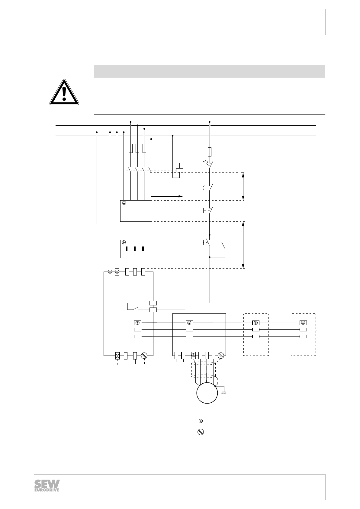
4.5.3 Wiring of power connections
L1 L2 L3
L1´ L2´ L3´
Line filter
L1
ON
L2
L3
PE
N
DC 24 V
X1
1 2 3
L1 L2 L3
PE
X4
–
+
PE
Sa
Sb
X19
1
2
Supply and
regenerative module
X3
–R
+R
PE
1
2
X4
–
+
PE
Axis module
X2
X6
Motor
1 2 3
2
1
Brake
control
PE U V W
X4
–
+
PE
Axis module
–
+
PE
Axis module
1
2
1
2
1
2
X4
Cable length ≤ 1.5 m
PE
= PE (housing grounding point)
= Power shield terminal
Emerg.
STOP***
K11
14
13
12345
6
23
24
A1
A2
K11
K11 **
OFF
F16 *
U1 V1 W1
U2 V2 W2
Choke
1
2
1
Cable length ≤ 5 m
Braking resistor
connection,
see next pages.
NOTICE
Irreparable damage to the supply and regenerative modules
Except for the line filter and the choke, no further components must be installed between the line contactor K11 and the supply and regenerative module. Otherwise,
the switch-on sequence cannot be performed correctly.
Installation
Wiring diagrams
4
9007203579744139
21219796 / EN – 04/2014
* When F16 (trip contact at overload relay) trips, K11 must open and "Output stage enable" must receive
a "0" signal. F16 is a signal contact, which means the resistor circuit must not be interrupted.
Manual MXR81.. – MOVIAXIS® Multi-Axis Servo Inverter
23
Installation
Wiring diagrams
4
** Emergency switching off release delay only in line with applicable system- and country-specific safety
regulations and customer specifications.
See MXR switch-on sequence (→ 2 38)
NOTICE
If the entire system should be disconnected from the supply system with a line disconnector (e.g. via main switch), proceed as follows:
• Decelerate and lock the axes, withdraw the "enable / charge" signal of the supply
and regenerative module.
• Interrupt the control of the line contactor K11 of the supply and regenerative
module.
24
21219796 / EN – 04/2014
Manual MXR81.. – MOVIAXIS® Multi-Axis Servo Inverter
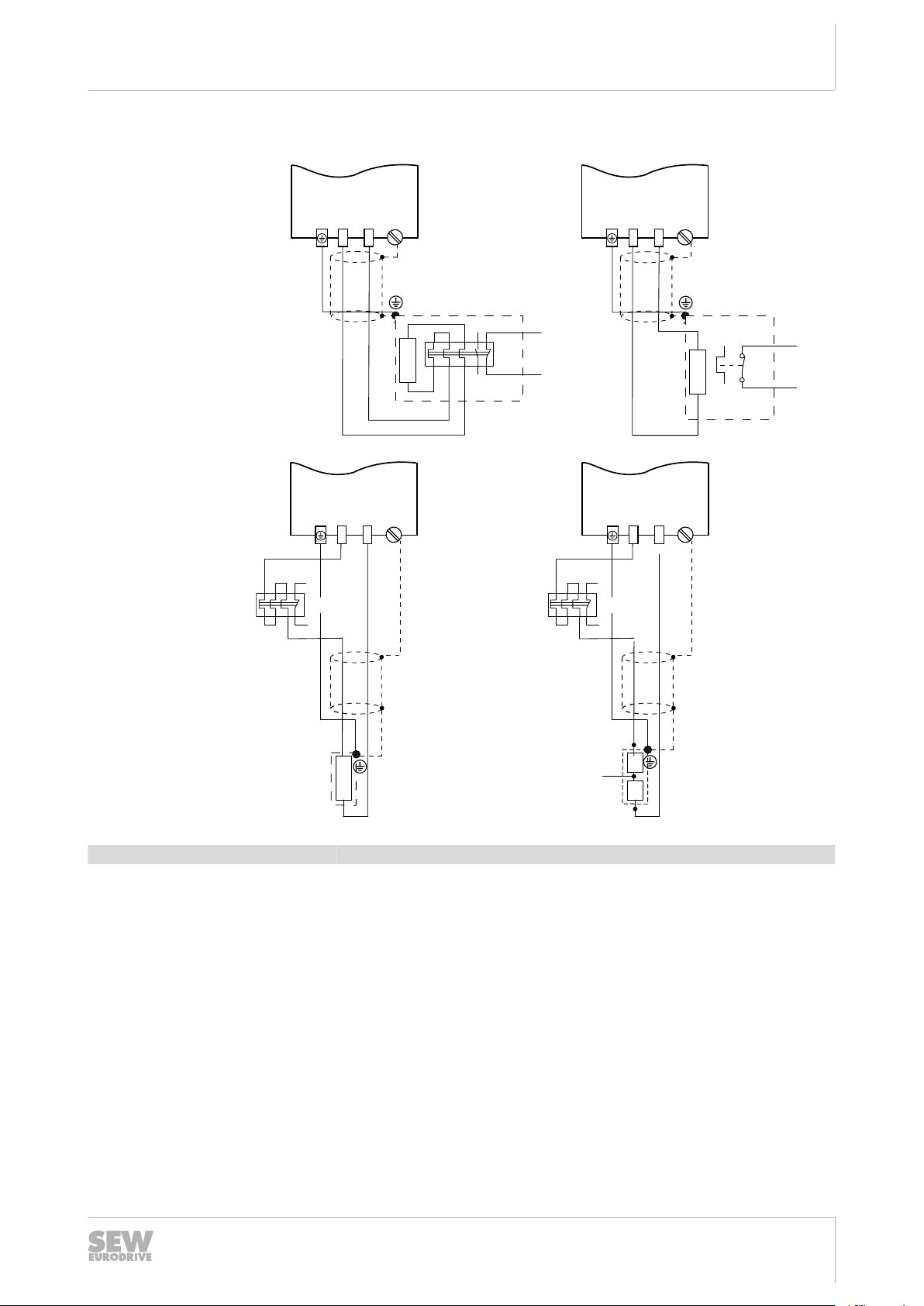
4.5.4 Braking resistor connection
T
2
T
1
affects
K11
BW...-...-T
RB2
RB1
BW...
F16
affects
K11
4 6
BW...-...-P
affects
K11
97
95
98
96
F16
Supply and
regenerative module
X3
–R
+R
PE
1
2
Supply and
regenerative module
X3
–R
+R
PE
1
2
Supply and
regenerative module
X3
–R
+R
PE
1
2
F16
BW...-01
F16
affects
K11
Supply and
regenerative module
X3
–R
+R
PE
1
2
1
2
3
Installation
Wiring diagrams
4
BW...-...-P BW...-...-T BW... , BW...-01
When the signal contact F16 trips, K11 must
open. When F16 (trip contact at overload relay or temperature switch) trips, K11 must
open and "Output stage enable" must receive a "0" signal. F16 is a signal contact,
which means the resistor circuit must not be
interrupted.
When the internal temperature switch trips,
K11 must open. When F16 (trip contact at
overload relay or temperature switch) trips,
K11 must open and "Output stage enable"
must receive a "0" signal. F16 is a signal
contact, which means the resistor circuit
must not be interrupted.
18014401455579147
When the external bimetal relay (F16) trips,
K11 must open. When F16 (trip contact at
overload relay or temperature switch) trips,
K11 must open and "Output stage enable"
must receive a "0" signal. F16 is a signal
contact, which means the resistor circuit
must not be interrupted.
If you want to use a DC link discharge module, it is essential that you contact
SEW‑EURODRIVE.
21219796 / EN – 04/2014
Manual MXR81.. – MOVIAXIS® Multi-Axis Servo Inverter
25

Installation
Wiring diagrams
4
Braking resistor type Overload protection
BW.. through external bimetal relay F16
BW...-01 through external bimetal relay F16
BW..-..-T
BW..-..-P through internal bimetal relay F16
• through internal temperature switch, or
• through external bimetal relay F16
26
21219796 / EN – 04/2014
Manual MXR81.. – MOVIAXIS® Multi-Axis Servo Inverter
4.6 Terminal assignment
PE
3
PE
2
PE
2
1
4
INFORMATION
Reference potentials inside the unit
The designation of the reference potentials is listed in the following table:
Installation
Terminal assignment
4
Designation
DGND
PE
BGND Reference potential for brake connection
RGND Reference potential for safety relay
DCOM Reference potential for digital inputs
Meaning
General reference potential of control electronics. There is a metallic
connection to PE.
INFORMATION
Connection elements:
All connection elements are represented in the following tables as viewed from top.
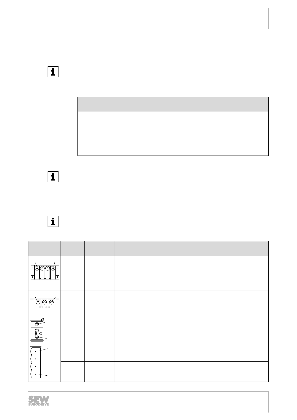
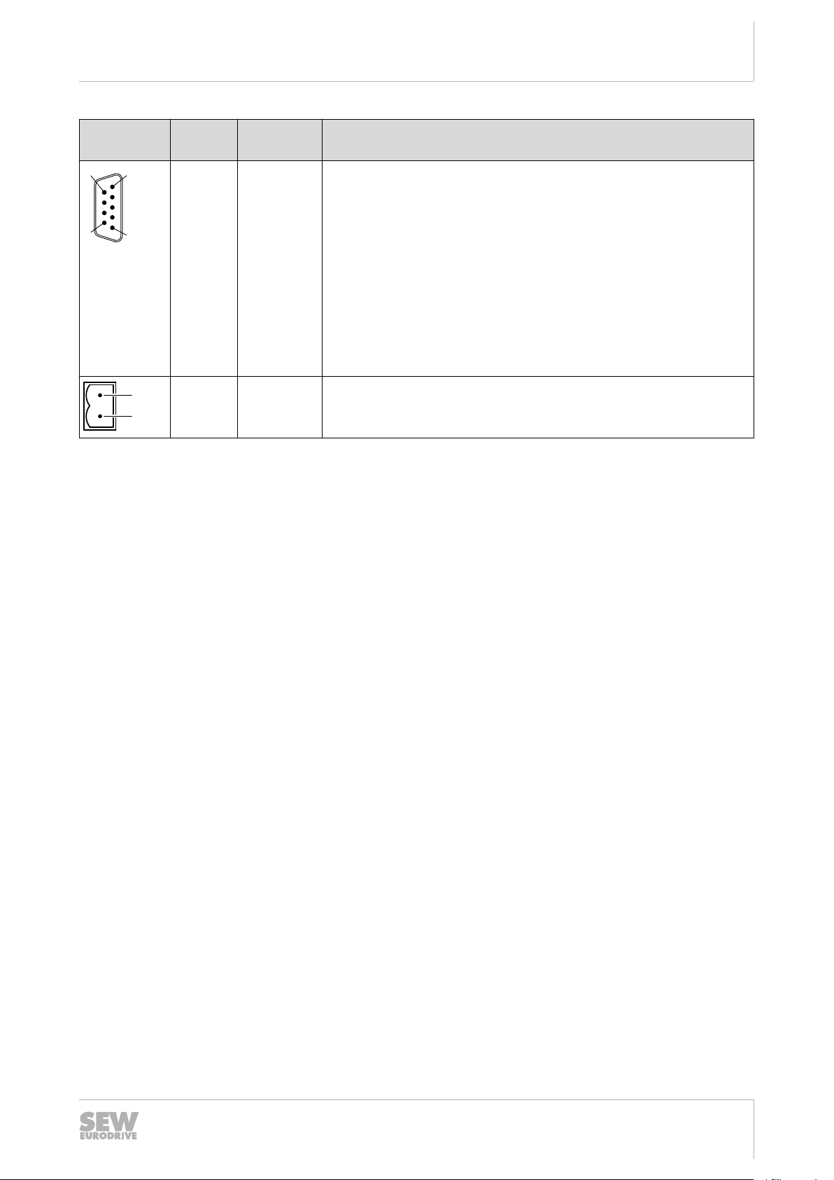
4.6.1 Terminal assignment of the supply and regenerative module
INFORMATION
The technical data of the power and control electronics connections are described in
chapter "Technical Data" in this manual and in the "MOVIAXIS® Multi-Axis Servo Inverter" operating instructions.
21219796 / EN – 04/2014
Terminal Assign-
ment
X1:PE
X1:1
X1:2
X1:3
X3:PE
X3:1
X3:2
X4:PE
X4:1
X4:2
X5a:1
X5a:2
X5a:3
X5a:4
PE
L1
L2
L3
PE
+R
-R
PE
+V
DCL
-V
DCL
+24 V
DGND
+24 V
BGND
E
B
Brief description
Line connection (MXR)
Braking resistor connection
DC link connection
Voltage supply for electronics
Voltage supply for brake
Manual MXR81.. – MOVIAXIS® Multi-Axis Servo Inverter
27
Installation
1
4
X9a
X9b
1
6
1
5
6
9
5
1
Terminal assignment
4
18014401455
736203
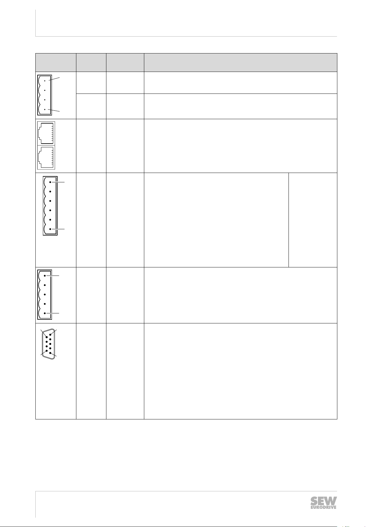
Terminal Assign-
ment
X5b:1
X5b:2
X5b:3
X5b:4
X9a
X9b
X10:1
X10:2
X10:3
X10:4
X10:5
X10:6
+24 V
DGND
+24 V
BGND
DIØØ
DIØ1
DIØ2
DIØ3
DCOM
DGND
E
B
Brief description
Voltage supply for electronics
Voltage supply for brake
a = input: Signaling bus, with green connector
b = output: Signaling bus, with red connector
Digital input 1; with fixed assignment "Output stage
enable"
Digital input 2; with fixed assignment "Enable/
charge"
Digital input 3; freely programmable, default: "Reset"
Digital input 4; freely programmable, default: "Line
contactor feedback"
Reference potential for digital inputs DIØØ – DIØ3
General reference potential of control electronics
Electrically isolated via optocoupler with reference to
DCOM (X10:5).
X11:1
X11:2
X11:3
X11:4
X11:5
X12:1
X12:2
X12:3
X12:4
X12:5
X12:6
X12:7
X12:8
X12:9
DOØØ
DOØ1
DOØ2
DOØ3
DGND
n.c.CAN_L
CAN_H
CAN_L
DGND
R
Abschluss
DGND
CAN_H
R
termination
Digital output 1, with fixed assignment "Ready for operation"
Digital output 2; fixed assignment with "Ready for power on "
Digital output 3; freely programmable
Digital output 4; freely programmable
Reference potential for digital outputs DOØØ – DOØ3
–
CAN1 bus low
Reference potential CAN1 bus
CAN1 bus low
Unit-internal bus terminating resistor
Reference potential CAN bus
CAN1 bus high
CAN1 bus high
Unit-internal bus terminating resistor
28
Manual MXR81.. – MOVIAXIS® Multi-Axis Servo Inverter
21219796 / EN – 04/2014
Installation
6
9
5
1
1
2
Terminal assignment
4
Terminal Assign-
ment
X17:1
X17:2
X17:3
X17:4
X17:5
X17:6
X17:7
X17:8
X17:9
X19:1
X19:2
n.c.CAN_L
CAN_H
CAN_L
DGND
R
Abschluss
DGND
CAN_H
R
termination
Sa
Sb
Brief description
–
CAN2 bus low
Reference potential CAN2 bus
CAN2 bus low
Unit-internal bus terminating resistor
Reference potential CAN2 bus
CAN2 bus high
CAN2 bus high
Unit-internal bus terminating resistor
Enable contact for line contactor
21219796 / EN – 04/2014
Manual MXR81.. – MOVIAXIS® Multi-Axis Servo Inverter
29

Startup
General information
5
5 Startup
This chapter describes in particular the startup of the MXR supply and regenerative
module.
For detailed information on the startup of the MOVIAXIS® axis system, refer to the
"MOVIAXIS® MX Multi-Axis Servo Inverter" operating instructions.
5.1 General information
WARNING
Uncovered power connections.
Severe or fatal injuries from electric shock.
• Never start the unit without protective covers and touch guards.
• Install protective covers and touch guards as instructed.
NOTICE
The MXR supply and regenerative module may only be switched on when the drives
are at standstill.
5.1.1 Requirements
Correct project planning for the drive is a prerequisite for successful startup. For detailed project planning information and an explanation of the parameters, refer to the
"MOVIAXIS® Multi-Axis Servo Inverter" system manual.
For starting up the entire axis system, observe the "Startup" chapter in the
"MOVIAXIS® Multi-Axis Servo Inverter" operating instructions.
INFORMATION
In addition to the requirements specified in the operating instructions and the system
manual for MOVIAXIS®, the MXA8... axis modules must be equipped with firmware .
24 or higher.
5.2 Settings on the supply and regenerative module with CAN-based system bus
The following settings are required:
• The CAN transmission rate is set using the two DIP switches S1 and S2 on the
supply and regenerative module, see the "MOVIAXIS® Multi-Axis Servo Inverter"
operating instructions, chapter "Assigning the CAN transmission rate".
• The address of the supply and regenerative module is set using the two address
switches S3 and S4. The other axis addresses are set automatically based on the
set device address.
21219796 / EN – 04/2014
30
Manual MXR81.. – MOVIAXIS® Multi-Axis Servo Inverter
 Loading...