

Page 1
Drive Technology \ Drive Automation \ System Integration \ Services
Manual
MOVITRAC
®
MC07B
Functional Safety
Edition 12/2011 19396414 / EN
Page 2
SEW-EURODRIVE—Driving the world
Page 3

Contents
Phone: 800.894.0412 - Fax: 888.723.4773 - Web: www.clrwtr.com - Email: info@clrwtr.com
Contents
1 General Information............................................................................................ 4
1.1 How to use this documentation................................................................... 4
1.2 Underlying standards.................................................................................. 4
1.3 Structure of the safety notes......................................... ... ........................... 5
1.4 Rights to claim under warranty ................................................................... 6
1.5 Exclusion of liability..................................................................................... 6
1.6 Copyright notice.......................................................................................... 6
1.7 Document content....................................................................................... 6
1.8 Other applicable publications...................................................................... 6
2 Integrated Safety Technology............................................................................ 7
2.1 Safe condition ........... .... ... ... ... .... ... .......................................... .................... 7
2.2 Safety concept ............................................................................................ 7
2.3 Schematic representation – "safety concept for MOVITRAC
2.4 Safety functions .......................................................................................... 9
2.5 Restrictions ............................................................................................... 11
3 Safety Conditions.............................................................................................. 12
3.1 Approved devices ..................................................................................... 13
3.2 Installation requirements........................................................................... 14
3.3 Requirements on the external safety controller ........................................ 16
3.4 Requirements on startup........................................................................... 17
3.5 Requirements on operation....................................................................... 17
4 Connection Variants ......... .... ... ... ... .... ... ... .......................................... ............... 18
4.1 General information ................................ ... ... ... ... .... ... ...... .... ... ... ... ... .... ... .. 18
4.2 Requirements............................................................................................ 19
4.3 Disconnection of a single drive ................................................................. 20
4.4 Disconnection of group drives................................................................... 26
5 Technical Data .................................................................................................. 30
5.1 Safety characteristics................................................................................ 30
5.2 Electronics data X17: Signal terminal block for STO safety contact......... 30
Index................................................................................................................... 31
®
B"............... 8
Manual – Functional Safety MOVITRAC® MC07B
3
Page 4
1
Phone: 800.894.0412 - Fax: 888.723.4773 - Web: www.clrwtr.com - Email: info@clrwtr.com
General Information
How to use this documentation
1 General Information
Functional Safety MOVITRAC® MC07B
1.1 How to use this documentation
The documentation is an integral part of the product and contains impo rtant information
on operation and service. The documentation is written for all employees wh o assemble,
install, start up, and service this product.
The documentation must be accessible and legi ble. Make sure that persons responsible
for the system and its operation, as well as persons wh o work independently on the unit,
have read through the documentation carefully and understood it. If you are unclear
about any of the information in this documentation, or if you require further information,
contact SEW-EURODRIVE.
Make sure you always use the latest documentation and software version.
Our documentation is available in various languages for download from the SEW
homepage
about any of the info
You can also order the printed documentat io n from SEW-E URODRIVE.
1.2 Underlying standards
The safety assessment of the unit is based on the following standards and safety
classes:
. Consult SEW-EURODRIVE if you are unclear
rmation in this docu
mentation, or if you require further information.
Underlying standards
Safety class/underlying standard
• Performance level (PL) according to EN ISO 138491:2008
• Category 3 according to EN 954-1:1996
4
Manual – Functional Safety MOVITRAC® MC07B
Page 5
1.3 Structure of the safety notes
Phone: 800.894.0412 - Fax: 888.723.4773 - Web: www.clrwtr.com - Email: info@clrwtr.com
1.3.1 Meaning of signal words
The following table shows the grading and meaning of the signal words for safety notes,
notes on potential risks of damage to propert y, an d ot he r no te s.
Signal word Meaning Consequences if disregarded
DANGER Imminent danger Severe or fatal injuries
WARNING Possible dangerous situation Severe or fatal injuries
CAUTION Possible dangerous situation Minor injuries
NOTICE Possible damage to property Damage to the drive system or its
INFORMATION Useful information or tip:
implifies the handling of the
drive system.
1.3.2 Structure of the section safety notes
Section safety notes do not apply to a specific action but to several actions pertaining to
one subject. The symbols used either indicate a general hazard or a specific hazard.
General Information
Structure of the safety notes
environment
1
This is the formal structure of a section safety note:
SIGNAL WORD
Type and source of danger.
Possible consequence(s) if disregarded.
• Measure(s) to prevent the danger.
1.3.3 Structure of the embedded safety notes
Embedded safety notes are directly integrated in the instructions just before the description of the dangerous action.
This is the formal structure of an embedded safety note:
• SIGNAL WORD Type and source of danger.
Possible consequence(s) if disregarded.
– Measure(s) to prevent the danger.
Manual – Functional Safety MOVITRAC® MC07B
5
Page 6

1
Phone: 800.894.0412 - Fax: 888.723.4773 - Web: www.clrwtr.com - Email: info@clrwtr.com
General Information
Rights to claim under warranty
1.4 Rights to claim under warranty
A requirement of fault-free operation and fulfillment of any rights to claim under limited
warranty is that you adhere to the information in the MOVITRAC
Therefore, read the operating instructions before you start working with the unit.
Make sure that the documentation is available to persons responsible for the system and
its operation as well as to persons who work independently on the unit. You must also
ensure that the documentation is legible.
1.5 Exclusion of liability
Adherence to the operating instructions is essential to ensure safe operation of
MOVITRAC
performance features. SEW-EURODRIVE assumes no liability for injury to persons or
damage to equipment or property resulting from non-adherence to these operating
instructions. In such cases, any liability for defects is excluded.
1.6 Copyright notice
© 2010 – SEW-EURODRIVE. All rights reserved.
Copyright law prohibits the unauthorized duplication, modification, distribution, and use
of this document, in whole or in part.
®
documentation.
®
MC07B units and to achieve the specified product characteristics and
1.7 Document content
This publication contains conditions and amendments related to MOVITRAC® MC07B
units in safety-related applications.
The system comprises a drive inverter with AC motor and safety-tested external
disconnecting device.
1.8 Other applicable publications
This document supplements the MOVITRAC® MC07B operating instructions and limits
the application notes according to the fo llowing information. It may only be used togeth er
with the MOVITRAC
®
MC07B operating instructions.
6
Manual – Functional Safety MOVITRAC® MC07B
Page 7

2 Integrated Safety Technology
Phone: 800.894.0412 - Fax: 888.723.4773 - Web: www.clrwtr.com - Email: info@clrwtr.com
The safety technology of MOVITR AC®MC07B units described below has been developed and tested in accordance with the following safety requirements:
• Category 3 according to EN 954-1: 1996
• PL d according to EN ISO 13849-1: 2008
This was certified by TÜV Nord. Copies of the TÜV certificate can be obtained from
SEW-EURODRIVE.
2.1 Safe condition
For safety-related operation of MOVITRAC®MC07B, safe torque off is defined as safe
condition (see STO safety function). The safety concept is based on this definition.
2.2 Safety concept
Integrated Safety Technology
Safe condition
2
• In the event of danger, any potential risk related to a machine must be eliminated as
quickly as possible. Standstill with restart prevention is generally the safe condition
for preventing dangerous movements.
®
• The MOVITRAC
external safety relay. This safety relay disconnects all active ele ments (disconnection of the safety-related 24 V power supply of the outpu t stage control) that generate
the pulse trains to the power output stage (IGBT) when a connected control device
(E-STOP button with latching function) is activated.
• Disconnecting the safety-related 24 V supply voltage ensures that the supply
voltages required for operating the inverter and consequently for generating a rotating field of pulse patterns (w hich allow the generation of a rotating field) are s afely
interrupted, preventing automatic restart.
• Instead of galvanic separation of the drive from the power supply by means of relays
or switches, the disconnection of the 24 V supply described here safely prevents the
control of the power semiconductors in the drive inverter. This process disconnects
the rotating field generation for the respective motor. The individual motor cannot
develop any torque in this state even though the line voltage is still present.
MC07B inverter is characterized by the option to connect an
Manual – Functional Safety MOVITRAC® MC07B
7
Page 8
2
Phone: 800.894.0412 - Fax: 888.723.4773 - Web: www.clrwtr.com - Email: info@clrwtr.com
Integrated Safety Technology
Schematic representation – "safety concept for MOVITRAC® B"
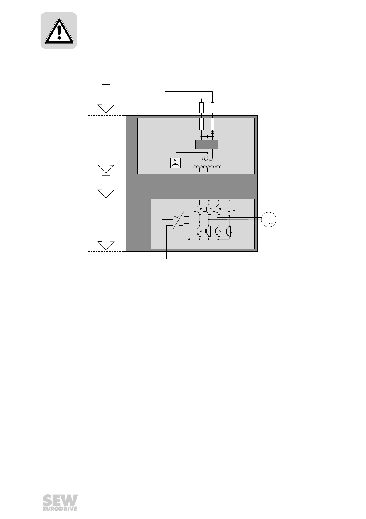
2.3 Schematic representation – "safety concept for MOVITRAC® B"
[1]
[2]
[3]
[4]
[1] Safety-related DC 24 V voltage supply
[2] Electrical isolation
[3] Voltage supply for control of power transistors
[4] Pulse width modulated signals for the output stage
L1 L2 L3
S24V
S0V24
Uz+
Uz-
GND
S0V24
SNT
24V
SVI24
M
1797262603
8
Manual – Functional Safety MOVITRAC® MC07B
Page 9
2.4 Safety functions
v
t
t
1
Phone: 800.894.0412 - Fax: 888.723.4773 - Web: www.clrwtr.com - Email: info@clrwtr.com
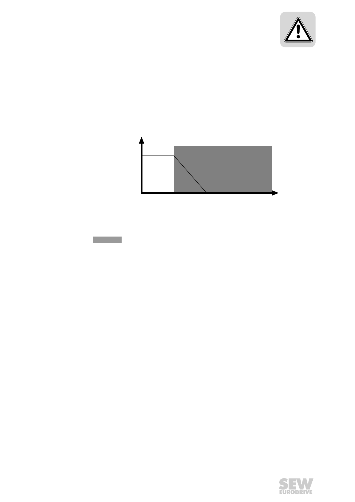
The following drive-related safety functions can be used:
• STO (safe torque off according to EN 61800-5-2) by disconnecting the STO input.
If the STO function is activated, the frequency inverter no longer supplies power to
the motor for generating torque. This safety function corresponds to a non- controlled
stop according to EN 60204-1, stop category 0.
The STO input must be disabled by a suitable external safety controller/safety relay.
The following figure shows the STO function:
Integrated Safety Technology
Safety functions
2
v Velocity
tTime
t
1
Time at which STO is triggered
Disconnection range
2463228171
Manual – Functional Safety MOVITRAC® MC07B
9
Page 10
2
v
t
t
1
tt
2
Phone: 800.894.0412 - Fax: 888.723.4773 - Web: www.clrwtr.com - Email: info@clrwtr.com
Integrated Safety Technology
Safety functions
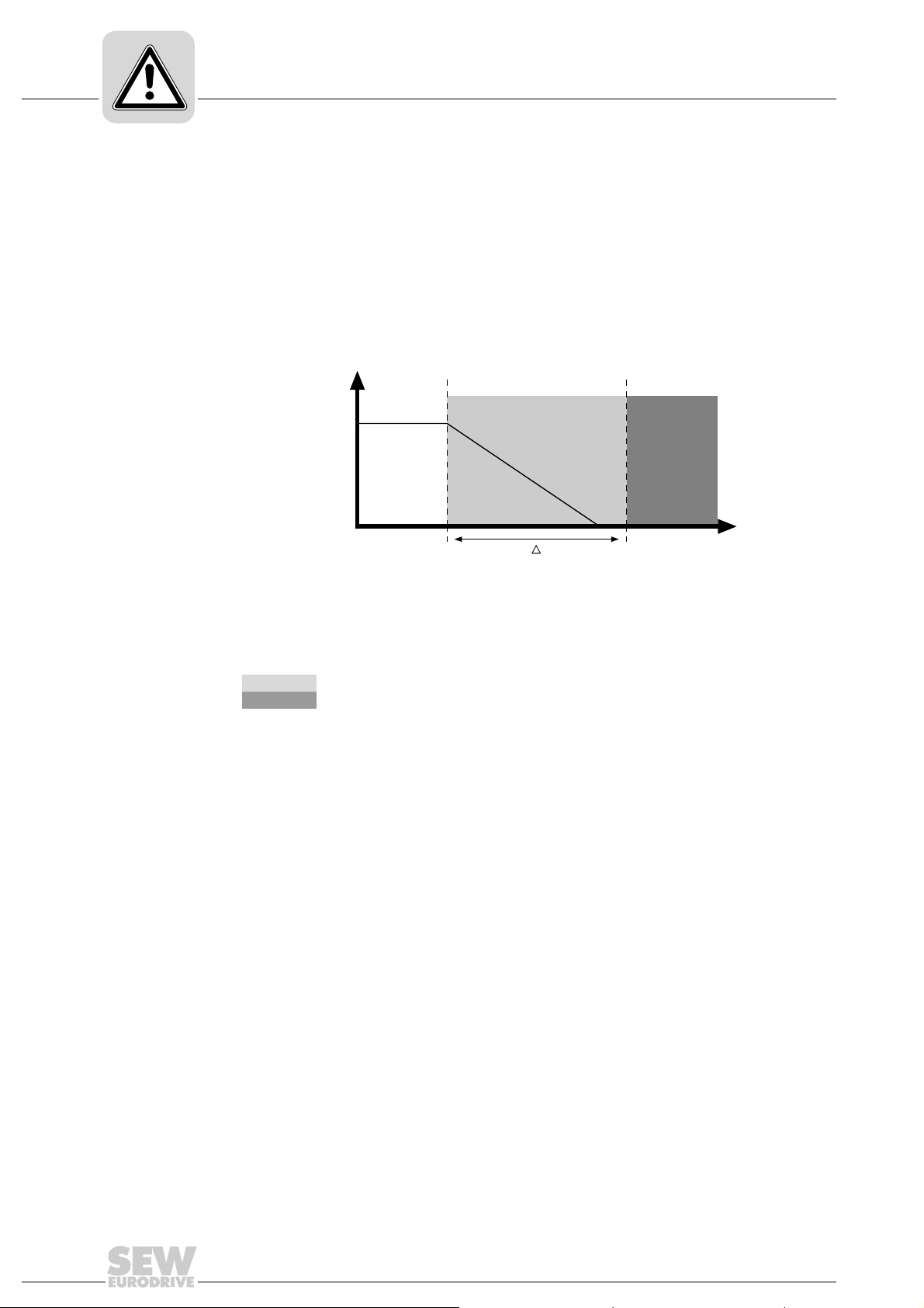
• SS1(c) (safe stop 1, function variant c according to EN 61800-5-2) by means of
suitable external control (e.g. safety relay with delayed disconnection)
The following sequence is mandatory:
– Decelerate the drive using an appropriate brake ramp specified via setpoints.
– Disconnect the STO input (= triggering the STO function) after a specified safety-
related time delay.
This safety function corresponds to a controlled stop according to EN 602041, stop
category 1.
The following figure illustrates the SS1(c) function:
v Velocity
tTime
t
1
t
2
∆t Time between initiating the brake ramp and STO
Point of time when the brake ramp is initiated
Point of time when STO is triggered
Safe time delay range
Disconnection range
2463226251
10
Manual – Functional Safety MOVITRAC® MC07B
Page 11

2.5 Restrictions
Phone: 800.894.0412 - Fax: 888.723.4773 - Web: www.clrwtr.com - Email: info@clrwtr.com
Integrated Safety Technology
Restrictions
• Note that if the drive does not have a mechanical brake, or if the brake is defective,
the drive may coast to a halt (depending on the friction and mass moment of inertia
of the system). In case of regenerative loads, the drive can even accelerate. This
must be taken into account in a risk assessment of the system/machine. Additional
safety measures might have to be implemented (e.g. safety brake system).
®
MOVITRAC
cation-specific safety functions that require active deceleration (braking).
• When using the SS1(c) function as described in chapter "Safety functions", the brake
ramp of the drive is not monitored with respect to safety. In case of a fault, the drive
might not be decelerated after the delay time, or it might be accelerated in the worst
case. In this case, th e STO function (s ee chapter "Safety functions") is only activated
after the set time delay has elapsed. The re sulting danger must be taken into account
in the risk assessment of the system/machine. Additional safety measures might
have to be implemented.
MC07B cannot be used without an additional brake system for appli-
2
WARNING
The safety concept is only suitable for performing mechanical work on the system/
machine components.
When the STO signal is disconnected, the line voltage is still present at the DC link of
MOVITRAC
Severe or fatal injuries from electric shock.
• Before working on the electric part of the drive system, disconnect it from the
supply system using an appropriate external disconnecting device and secure it
against unintentional reconnection to the power supply.
®
MC07B.
INFORMATION
In case of safety-related disconnection of the DC 24 V supply at X17 (STO activated),
the brake is always applied. The brake control in MOVITR AC
related.
®
MC07B is not safety-
Manual – Functional Safety MOVITRAC® MC07B
11
Page 12

3
Phone: 800.894.0412 - Fax: 888.723.4773 - Web: www.clrwtr.com - Email: info@clrwtr.com
Safety Conditions
3 Safety Conditions
The requirement for safe operation is that the safety functions of MOVITRAC® MC07B
are properly integrated into an application-specific higher-level safety function. A
system/machine-specific risk assessment must be carried out by the system/machine
manufacturer and taken into account for operating the drive system with MOVITRAC
MC07B.
The system/machine manufacturer and the operator are responsible for compliance of
the system/machine with applicable safety regulations.
The following requirements are mandatory when installing and operating MOVITRAC
MC07B units in safety-related applications.
The requirements are divided into:
• Approved devices
• Requirements on the installation
• Requirements on external safety controllers and safety relays
• Requirements on startup
®
®
• Requirements on operation
12
Manual – Functional Safety MOVITRAC® MC07B
Page 13

3.1 Approved devices
Phone: 800.894.0412 - Fax: 888.723.4773 - Web: www.clrwtr.com - Email: info@clrwtr.com
The following unit variants of MOVITRAC® MC07B are permitted for safety-related
applications:
®
3.1.1 MOVITRAC
MC07B for a supply voltage of 3 × AC 380 – 500 V
Safety Conditions
Approved devices
3
3.1.2 MOVITRAC
Power
kW
0.55 0S MC07B0005-5A3-4-S0
0.75 0S MC07B0008-5A3-4-S0
1.1 0S MC07B0011-5A3-4-S0
1.5 0S MC07B0015-5A3-4-S0
2.2 0L MC07B0022-5A3-4-S0
3.0 0L MC07B0030-5A3-4-S0
4.0 0L MC07B0040-5A3-4-S0
5.5 2S MC07B0055-5A3-4-00
7.5 2S MC07B0075-5A3-4-00
11 2 MC07B0110-5A3-4-00
15 3 MC07B0150-503-4-00
22 3 MC07B0220-503-4-00
30 3 MC07B0300-503-4-00
37 4 MC07B0370-503-4-00
45 4 MC07B0450-503-4-00
55 5 MC07B0550-503-4-00
75 5 MC07B0750-503-4-00
®
MC07B for a supply voltage of AC 200 – 240 V
Power
kW
0.55 0S MC07B0005-2A3-4-S0
0.75 0S MC07B0008-2A3-4-S0
1.1 0L MC07B0011-2A3-4-S0
1.5 0L MC07B0015-2A3-4-S0
2.2 0L MC07B0022-2A3-4-S0
3.7 1 MC07B0037-2A3-4-00
5.5 2 MC07B0055-2A3-4-00
7.5 2 MC07B0075-2A3-4-00
11 3 MC07B0110-203-4-00
15 3 MC07B0150-203-4-00
22 4 MC07B0220-203-4-00
30 4 MC07B0300-203-4-00
Size Type
Size Type
Manual – Functional Safety MOVITRAC® MC07B
13
Page 14

3
Phone: 800.894.0412 - Fax: 888.723.4773 - Web: www.clrwtr.com - Email: info@clrwtr.com
Safety Conditions
Installation requirements
3.2 Installation requirements
• For size 0 units of the type MC07B...-S0, an external 24V supply must always be
connected because the control electronics can only be powered in this way.
• The safety-related DC 24 V supply voltage must be routed according to EMC guidelines as follows:
– Outside an electrical installation space, shielded cables must be routed perma-
– Individual conductors can be routed inside an electrical installation space.
– Adhere to the regulations in force for the application.
• Power lines and safety-related control lines have to be installed in separate cables.
• Make sure that no parasitic voltages can be generated in the safety-related control
lines.
• Wiring technology must comply with EN 60204-1.
• Use only grounded voltage sources with safe isolation (PELV) according to VDE0100
and EN 60204-1. In case of a single fault, the voltage between the outputs or
between any output and grounded parts must not exceed DC 60 V.
• Observe the notes in the "MOVITRAC
tion on EMC-compliant cabling. It is essential that you connect the shield of the
safety-related DC 24 V supply cable to the housing at both ends.
nently (fixed) and protected against external damage, or other equivalent measures have to be taken.
®
MC07B" operating instructions for informa-
• The lines of the safety-related 24 V voltage supply (terminal X17) must be clamped
under the signaling electronics shield clamp.
®
• When planning the installation, observe the technical data of MOVITRAC
• Observe the values specified for safety components when designing the safety circuits.
• The cable length of the safety-related DC 24 V supply may not exceed 100 m.
• The safety-related DC 24 V supply may not be used for feedback.
MC07B.
14
Manual – Functional Safety MOVITRAC® MC07B
Page 15

Safety Conditions
Phone: 800.894.0412 - Fax: 888.723.4773 - Web: www.clrwtr.com - Email: info@clrwtr.com
Installation requirements
• All connections (such as lines or data communication using bus systems) must
already have been taken into account in the performance level of one of the subsystems involved, or it must be possible that faults in the connections can be
excluded or neglected.
The fault assumption "short circuit between any two conductors" can be excluded
according to EN ISO 13849-2: 2008 under the following cond itions:
The conductors are
– permanently (fixed) installed and protected against external dam age (for example
using a cable duct or armored conduit)
– installed in different light plastic-sheathed cables in an electrical installation space
provided that both the lines and the installation space meet the relevant require-
ments, see EN 60204-1
– protected individually by a ground connection
The fault assumption "short circuit between any conductor and an exposed conduc-
tive part or earth or a protective conductor" can be excluded under the following
conditions:
3
– Short circuit between conductor and any exposed conductive part in an installa-
tion space.
• For applications with safety-related disconnection of the drive, remove the jumpers
on X17:1 to X17:4 (→ following figure).
X17
SVI
24V
GND
SOV
1797603595
Removing jumpers
Manual – Functional Safety MOVITRAC® MC07B
15
Page 16

3
Phone: 800.894.0412 - Fax: 888.723.4773 - Web: www.clrwtr.com - Email: info@clrwtr.com
Safety Conditions
Requirements on the external safety controller
3.3 Requirements on the external safety controller
[6]
[3]
[2] U
[1] Safety relay with approval
[2] DC 24 V voltage supply
[3] Fuses in accordance with the manufacturer's specifications of the safety relay
[4] Safety-related DC 24 V voltage supply
[5] Reset button for manual reset
[6] Approved EMERGENCY STOP actuating device
[1]
[4]
[5]
1593958923
A safety relay can be used as an alternative to a safety controller. The following requirements apply analogously.
• The safety controller and all other safety-related subsystems must be approved for
at least that safety class which is required in the overall system for the respective,
application-related safety function.
The following table shows an example of the required safety class of the safety
controller:
Application Safety controller requirements
Performance level d according to EN ISO
13849-1
16
Performance level d according to EN ISO
13849-1
SIL 2 according to EN 61508
Manual – Functional Safety MOVITRAC® MC07B
Page 17

Safety Conditions
Phone: 800.894.0412 - Fax: 888.723.4773 - Web: www.clrwtr.com - Email: info@clrwtr.com
Requirements on startup
• The wiring of the safety controller must be suitable for the re quired safety class, (see
manufacturer documentation).
– If the DC 24 V supply is safely disconnected at the positive pole only, no test
pulses must be applied to this pole in disconnected condition.
If the DC 24 V supply is disconnected at both poles, the test pulses must not be
applied at the same time at the plus and minus outputs. In this ca se, the test pulse
must be applied with a time delay.
– SEW-EURODRIVE recommends to switch off the 24 V supply at two poles.
• The values specified for the safety controller must be strictly adhered to when designing the circuit.
• The switching capacity of the safety relays or the relay outputs of the safety controller
must correspond at least to t he maximally permitted, limited output current of the
24 V voltage supply.
Observe the manufacturer's instructions concerning the permitted contact loads and
fusing that may be required for the safety contacts. If the manufacturer provides no
specific information, the contacts must be protected with 0.6 times the nominal value
of the maximum contact rating specified by the man uf ac tu re r.
3
• To ensure protection against unintended restart in accordance with EN 1037, the
safe control system must be designed and conn ected in such a way that resetting the
control device alone does not lead to a restart. A restart may only be carried out after
a manual reset of the safety circuit.
3.4 Requirements on startup
• To validate the implemented safety functions, they must be documented and
checked after successful startup (validation).
Observe the limitations for safety functions in chapter "Limitations" for the validation
of the safety functions. Non-safety-related parts and components that affect the
result of the validation test (e.g. motor brake) must be deactivated, if necessary.
• For using MOVITRAC
perform and record startup checks for the disconne cting device and for proper wiring.
3.5 Requirements on operation
• Operation is only allowed within the limits specified in the data sheets. This principle
applies to the external safety control as well as toMOVITRAC
options.
• You must check the safety functions on a regular basis to ensure proper functioning.
The test intervals should be specified in accordance with the risk assessment.
®
MC07B in safety-relevant applications, it is essential that you
®
MC07B and approved
Manual – Functional Safety MOVITRAC® MC07B
17
Page 18

4
Phone: 800.894.0412 - Fax: 888.723.4773 - Web: www.clrwtr.com - Email: info@clrwtr.com
Connection Variants
General information
4 Connection Variants
4.1 General information
Generally, all the connection variants listed in this documentation are permitted for
safety-relevant applications as long as the basic safety concept is met. This means you
have to make sure that the DC 24 V safety inputs are operated by an external safety
relay or a safety controller, thus preventing an automatic restart.
All safety conditions mentioned in chapter 2, 3 and 4 of this documentation must be met
for the basic selection, installation, and application of the safety components, such as
safety relay, EMERGENCY STOP switch, etc., and the approved connection variants.
The wiring diagrams are block diagrams whose only purpose is to show the safety
function(s) with the relevant components. Circuit-related measures, which usually
always have to be implemented additionally, are not shown in the diagrams to enhance
clarity. Such measures are tak en, fo r exa mple, to ensure protection against contact, to
handle overvoltage and undervoltage, to detect insulation faults, line-to-ground faults
and short circuits, which can occur on externally installed lines, or to ensure the necessary immunity against electromagnetic interference.
4.1.1 X17 terminal on MOVITRAC
The following figure shows the X17 terminal at the bottom of the control unit.
®
MC07B
[1]
X17
[1]
* View of the underside of the unit
[1] X17: Signal terminal block for STO safety contacts
18
Manual – Functional Safety MOVITRAC® MC07B
3210370059
Page 19

4.2 Requirements
<1ms >1000ms
High
Low
t
Phone: 800.894.0412 - Fax: 888.723.4773 - Web: www.clrwtr.com - Email: info@clrwtr.com
4.2.1 Use of safety relays
The requirements of the manufacturers of safety relays (such as protecting the output
contacts against welding) or other safety components must be strictly observed. For
cable routing, the basic requirements apply as described in this publication.
For connecting MOVITRAC
ments in chapter "Installation requirements" (page 14).
Other instructions by the manufacturer on the use of safety relays for specific applications must also be observed.
4.2.2 Use of safety relays
Observe the ZVEI specifications for safety sensors if you use a safety PLC.
The starting and stopping pulses of the safe digital outputs ( F-DO) used must be ≤ 1ms.
The ratio must not fall below 1:1000.
Connection Variants
Requirements
®
with the safety relays, observe the installation require-
4
3211043979
INFORMATION
If the DC 24 V supply at X17 is switched off safely (STO activated), you must observe
chapter "Requirements on the ex ternal safe ty contro ller (page 16)" with regard to the
test pulses.
Manual – Functional Safety MOVITRAC® MC07B
19
Page 20

4
t
n
X17
X12:4
X12:1
Phone: 800.894.0412 - Fax: 888.723.4773 - Web: www.clrwtr.com - Email: info@clrwtr.com
Connection Variants
Disconnection of a single drive
4.3 Disconnection of a single drive
4.3.1 STO according to PL d (EN ISO 13849-1)
The procedure is as follows:
• Recommendation: X12:1 and X12:4 are discon nected at the same time, e.g. in case
of an emergency stop.
• The 24 V safety input X17 is disabled.
• The motor coasts to a halt, if no brake is installed.
STO – Safe Torque Off (EN 61800-5-2)
4949829771
INFORMATION
• The illustrated STO disconnections can be used up to PL d according to
EN ISO 13849-1 taking account of chapter "Requirements" (page 19).
•MOVITRAC
®
MC07B size 0 requires an external DC 24 V voltage supply.
20
Manual – Functional Safety MOVITRAC® MC07B
Page 21

Binary control with safety relay (dual-channel)
+24 V
Feedback
emergency stop
Reset
Higher-level
controller
PLC
IN
OUT
Safety
relay
Emerg. stop
Start
Stop
GND
Mains
MC07B
2
X12
1
4
X17
456
1
2
3
4
'0'=Controller inhibit
'1'=Controller enable
'0'=Stop
'1'=START CW
'0'=Rapid stop
'1'=Enable
8
24VIO
9
GND
DGND
VO24
SVI24
SOV24
X2
M
UVW
+24 V
Feedback
emergency stop
Reset
Higher-level
controller
PLC
IN
OUT
Safety
relay
Emerg. stop
Start
Stop
Mains
MC07B
2
X12
1
4
X17
456
1
2
3
4
'0'=Controller inhibit
'1'=Controller enable
'0'=Stop
'1'=START CW
'0'=Rapid stop
'1'=Enable
8
24VIO
9
GND
DGND
VO24
SVI24
SOV24
X2
M
UVW
Phone: 800.894.0412 - Fax: 888.723.4773 - Web: www.clrwtr.com - Email: info@clrwtr.com
Connection Variants
Disconnection of a single drive
4
Binary control with safety relay (single-channel)
4891650443
4891648523
INFORMATION
With single-channel disconnection, certain fault assumptions have to be made and
handled through fault exclusion. Observe the "Requirements" (page 19) chapter.
SEW-EURODRIVE recommends to switch off the 24 V supply of the STO input X17
at two poles.
Manual – Functional Safety MOVITRAC® MC07B
21
Page 22

4
+24 V
Higher-level
controller
Standard Safe
IN
OUT
Emerg. stop
Start
Stop
GND
Mains
IN
OUT
MC07B
2
X12
1
4
X17
456
1
2
3
4
'0'=Ctrl. inhibit
'1'=Ctrl. enable
'0'=Stop
'1'=START CW
'0'=Rapid stop
'1'=Enable
8
9
24VIO
GND
DGND
VO24
SVI24
SOV24
X2
M
UVW
+24 V
Higher-level
controller
Standard
Safe
IN
Emerg. stop
Start
Stop
GND
GND
Mains
IN
MC07B
X12
X30
DFS 21B
X17
456
1
2
3
4
DGND
VO24
SVI24
SOV24
(GND)
(24 V_LS)
GND
(F_DO_M)
(F_DO_P)
24VIO
X2
M
UVW
1
2
3
4
8
9
PROFINET
PROFIsafe
Phone: 800.894.0412 - Fax: 888.723.4773 - Web: www.clrwtr.com - Email: info@clrwtr.com
Binary control with safety PLC
Connection Variants
Disconnection of a single drive
Fieldbus control with safety PLC
4891654283
4891656203
INFORMATION
• Controller inhibit/enable and rapid stop/enable are set via fieldbus.
• Note the respective fieldbus manuals, e.g.
– "DFS11B PROFIBUS DP-V1 Fieldbus Interface with PROFIsafe" manual
– "DFS21B PROFINET IO Fieldbus Interface with PROFIsafe" manual
22
Manual – Functional Safety MOVITRAC® MC07B
Page 23

4.3.2 SS1(c) according to PL d (EN ISO 13849-1)
Phone: 800.894.0412 - Fax: 888.723.4773 - Web: www.clrwtr.com - Email: info@clrwtr.com
The procedure is as follows:
• X12:1 must not be disconnected.
• X12:4 is disconnected, e.g. in case of an emergency stop.
• During the safety time interval t
ramp.
Connection Variants
Disconnection of a single drive
, the motor decelerates to a complete stop along the
1
4
• After t
has elapsed, the safety input X17 is disconnected. The safety time interval t
1
must be sufficient for the motor to reach a complete stop.
SS1(c) – Safe Stop 1 (EN 61800-5-2)
X12:1
X12:4
X17
n
t
1
t
4949929739
INFORMATION
• The illustrated SS1(c) disconnections can be used up to PL d according to
EN ISO 13849-1 taking account of chapter "Requirements" (page 19).
•MOVITRAC
®
MC07B size 0 requires an external DC 24 V voltage supply.
1
Manual – Functional Safety MOVITRAC® MC07B
23
Page 24

4
+24 V
Feedback
emergency stop
Reset
Higher-level
controller
PLC
IN
OUT
Safety
relay
Emerg. stop
Start
Stop
GND
Mains
MC07B
2
X12
1
4
X17
456
1
2
3
4
'0'=Controller inhibit
'1'=Controller enable
'0'=Stop
'1'=START CW
'0'=Rapid stop
'1'=Enable
8 24VIO
9 GND
DGND
VO24
SVI24
SOV24
X2
M
UVW
t
1
+24 V
Feedback
emergency stop
Reset
Higher-level
controller
PLC
IN
OUT
Safety
relay
Emerg. stop
Start
Stop
Mains
MC07B
2
X12
1
4
X17
456
1
2
3
4
'0'=Controller inhibit
'1'=Controller enable
'0'=Stop
'1'=START CW
'0'=Rapid stop
'1'=Enable
8
24VIO
9
GND
DGND
VO24
SVI24
SOV24
X2
M
UVW
t
1
Phone: 800.894.0412 - Fax: 888.723.4773 - Web: www.clrwtr.com - Email: info@clrwtr.com
Connection Variants
Disconnection of a single drive
Binary control with safety relay (dual-channel)
Binary control with safety relay (single-channel)
4891646603
INFORMATION
With single-channel disconnection, certain fault assumptions have to be made and
handled by fault exclusion. Observe the "Requirements" (page 19) chapter.
SEW-EURODRIVE recommends to switch off the 24 V supply of the STO input X17
at two poles.
24
Manual – Functional Safety MOVITRAC® MC07B
4891658123
Page 25

Binary control with safety PLC
+24 V
Higher-level
controller
Standard Safe
IN
OUT
Emerg. stop
Start
Stop
GND
Mains
IN
OUT
MC07B
2
X12
1
4
X17
456
1
2
3
4
'0'=Ctrl. inhibit
'1'=Ctrl. enable
'0'=Stop
'1'=START CW
'0'=Rapid stop
'1'=Enable
8
9
24VIO
GND
DGND
VO24
SVI24
SOV24
X2
M
UVW
+24 V
Higher-level
controller
Standard
Safe
IN
Emerg. stop
Start
Stop
GND
GND
Mains
IN
MC07B
X12
X30
DFS 21B
X17
456
1
2
3
4
DGND
VO24
SVI24
SOV24
(GND)
(24 V_LS)
GND
(F_DO_M)
(F_DO_P)
24VIO
X2
M
UVW
1
2
3
4
8
9
PROFINET
PROFIsafe
Phone: 800.894.0412 - Fax: 888.723.4773 - Web: www.clrwtr.com - Email: info@clrwtr.com
Connection Variants
Disconnection of a single drive
4
Fieldbus control with safety PLC
4891654283
4891656203
INFORMATION
• Controller inhibit/enable and rapid stop/enable are set via fieldbus.
• Note the respective fieldbus manuals, e.g.
– "DFS11B PROFIBUS DP-V1 Fieldbus Interface with PROFIsafe" manual
– "DFS21B PROFINET IO Fieldbus Interface with PROFIsafe" manual
Manual – Functional Safety MOVITRAC® MC07B
25
Page 26

4
Phone: 800.894.0412 - Fax: 888.723.4773 - Web: www.clrwtr.com - Email: info@clrwtr.com
Connection Variants
Disconnection of group drives
4.4 Disconnection of group drives
This chapter describes how several MOVITRAC® MC07B units are controlled safely.
INFORMATION
SEW-EURODRIVE does not recommend group disconnection via safety PLC.
4.4.1 Requirements
For group drives, the 24 V safety inputs of several MOVITRAC
be made available by a single safety relay. The maximum number of axis modules
results from the maximum permitted contact load of the safety rela y or safety controller .
Other requirements of the manufacturers of safety relays (s uch as protecting the output
contacts against welding) or other safety components must be strictly observed. For
cable routing, observe the basic requirements in chapter "Installation requirements"
(page 14).
For connecting MOVITRAC
requirements in chapter "Installation requirements" (page 14).
Other instructions by the manufacturer on the use of safety relays for specific applications must also be observed.
®
MC07B inverters can
®
inverters with safety relays, observe the installation
Determining the maximum number of MOVITRAC
The number (n units) of MOVITRAC
disconnection is limited by the following points:
1. Switching capacity of the safety relay.
A fuse must be connected in front of the safety contacts according to the specifica-
tions of the emergency stop relay manufacturer to prevent contact welding.
The project planner is responsible for ensuring that the specifications for the switch-
ing capacity to EN 60947-4-1, 02/1 and EN 60947-5-1, 11/97 as well as on contact
fuse protection given in the operating instructions of the safety relay manufacturer
are strictly observed.
2. Maximum permitted voltage drop in the 24 V power supply cable.
Values concerning cable lengths and permitted voltage drops must be observed
during project planning for axis systems.
3. Maximum cable cross section of 1 × 1.5 mm
4. Power consumption of STO input X17: Input voltage, see chapter "Technical Data"
(page 30).
5. When using self-testing semiconductor outputs, the increased capacitances of STO
input X17 caused by group disconnection (parallel connection) might result in
diagnostics errors.
®
units for group disconnection
®
MC07B units that can be controlled with group
2
or 2 × 0.75 mm2.
26
Manual – Functional Safety MOVITRAC® MC07B
Page 27

Disconnection of group drives
MC07B
Safety
relay (SG)
®
Control cabinet
X17
X17
X17
BG0BG0
BG3 BG3
X17 X17
BG3
SG1
MOVITRAC
MC07B
MC07B
MC07B
MC07B
MC07
Safety
relay (SG)
®
Control cabinet
X17
X17
X17
BG0BG0
BG3
MC07
BG3
X17 X17
BG3
MOVITRAC
SG1 SG1
MC07 MC07
MC07
P
i
f
kVA
Hz
n
Phone: 800.894.0412 - Fax: 888.723.4773 - Web: www.clrwtr.com - Email: info@clrwtr.com
4.4.2 Implementing group disconnection with a safety relay
Group disconnection with one safety relay
The safety inputs of all MOVITRAC
®
MC07B can be controlled with one safety relay.
Connection Variants
4
Group disconnection with two safety relays
The safety inputs of the assigned MOVITRAC
several safety relays. In the following example, MOVITRAC
®
and MOVITRAC
MC07B size 0 inverters each form one group, and each group is
controlled by a safety relay.
4892037259
®
MC07B inverters can be controlled with
®
MC07B size 3 inverters
Manual – Functional Safety MOVITRAC® MC07B
4891918091
27
Page 28

4
t
n
X17
X12:4
X12:1
Phone: 800.894.0412 - Fax: 888.723.4773 - Web: www.clrwtr.com - Email: info@clrwtr.com
4.4.3 STO according to PL d (EN ISO 13849-1)
Connection Variants
Disconnection of group drives
The procedure is as follows:
• Recommendation: X12:1 and X12:4 are discon nected at the same time, e.g. in case
of an emergency stop.
• The 24 V safety input X17 is disconnected.
• The motor coasts to a halt, if no brake is installed.
STO – Safe Torque Off (EN 61800-5-2)
4949829771
INFORMATION
The displayed STO disconnections can be used up to PL d according to EN ISO
13849-1.
28
Manual – Functional Safety MOVITRAC® MC07B
Page 29

Connection Variants
Phone: 800.894.0412 - Fax: 888.723.4773 - Web: www.clrwtr.com - Email: info@clrwtr.com
Disconnection of group drives
Example: Group disconnection with three MOVITRAC® MC07B
4
Mains
Safety
relay
+24 V
Emergency stop
GND
Stop
Start
Feedback
emergency stop
Reset
Higher-level
controller
PLC
IN
OUT
Power supply connection
X12
'0'=Controller inhibit
1
'1'=Controller enable
'0'=Stop
2
'1'=START CW
'0'=Rapid stop
4
'1'=Enable
8
24VIO
9
GND
X17
DGND
1
VO24
2
3
SOV24
SVI24
4
Power supply connection
X12
'0'=Controller inhibit
1
'1'=Controller enable
'0'=Stop
2
'1'=START CW
'0'=Rapid stop
4
'1'=Enable
8
24VIO
9
GND
X17
DGND
1
VO24
2
3
SOV24
SVI24
4
Power supply connection
1
MC07B
1
2
X1
2
X1
MC07B
L3L2L1
3
X2
4 56
UVW
M
L3L2L1
3
X2
4 56
UVW
M
Manual – Functional Safety MOVITRAC® MC07B
X12
'0'=Controller inhibit
1
'1'=Controller enable
'0'=Stop
2
'1'=START CW
'0'=Rapid stop
4
'1'=Enable
8
24VIO
9
GND
X17
DGND
1
VO24
2
3
SOV24
SVI24
4
1
2
X1
MC07B
L3L2L1
3
X2
4 56
UVW
M
29
Page 30

5
P
i
f
kVA
Hz
n
Phone: 800.894.0412 - Fax: 888.723.4773 - Web: www.clrwtr.com - Email: info@clrwtr.com
5 Technical Data
Technical Data
Safety characteristics
The table below shows the technical data of MOVITRAC® MC07B related to integrated
safety technology. The technical data and approvals in the respective MOVITRAC
MC07B operating instructions must also be observed.
5.1 Safety characteristics
Safety characteristics
Tested safety class / underlying standards • Category 3 according to EN 954-1
Probability of dangerous failure per hour (PFH
value)
Service life 20 years, after which the component must be replaced with a new one.
Safe condition Safe torque off (STO)
Safety function STO, SS1
1) With suitable external control
• Performance Level d according to EN ISO 13849-1
0 (fault exclusion)
1)
according to EN 61800-5-2
5.2 Electronics data X17: Signal terminal block for STO safety contact
MOVITRAC® MC07B General electronics data
Safety contact X17:1
X17:2
X17:3
X17:4
Permitted cable cross section
DGND: Reference potential for X17:2
VO24: : V
supply other units.
SOV24: Reference potential for DC +24 V "STO" input (safety contact)
SVI24: DC+24 V "STO" input (safety contact)
One core per terminal: 0.08...1.5 mm
Two cores per terminal: 0.25 ... 1.0 mm
= DC 24 V, only to supply X17:4 of the same unit; cannot be used to
OUT
2
(AWG28...16)
2
(AWG23...17)
®
Power consumption X17:4
Input capacitance X17:4
Technical data of the STO input Min. Typical Max.
Input voltage range DC 19.2 V DC 24 V DC 30 V
Time to inhibit the output stage BG0 = 20 ms
Time for restart 200 ms
Size 0: 3 W
Size 1: 5 W
Size 2: 6 W
Size 3: 7.5 W
Size 4: 8 W
Size 5: 10 W
Size 0: 27 µF
Sizes 1 to 5: 270 µF
BG1 – 5 = 100 ms
30
Manual – Functional Safety MOVITRAC® MC07B
Page 31

Index
Phone: 800.894.0412 - Fax: 888.723.4773 - Web: www.clrwtr.com - Email: info@clrwtr.com
Index
A
Approved devices ..................................................13
C
Checking the disconnection device. ... .... ... ...... .... ...17
Connection variants ...............................................18
Copyright notice.......................................................6
D
Disconnection of a single drive .... ... ... .... ... ... ... .......20
STO according to PL d (EN 13849-1)... ... ... .... ...20
Disconnection of group drives................................26
Requirements.....................................................26
Disconnection of single drive
Requirements.....................................................19
Document content..................... ... ... ... .... ... ... ... .... ... ..6
E
Embedded safety notes ...........................................5
Exclusion of liability..................................................6
External safety controller........................................16
G
Group disconnection
STO according to PL d (EN 13849-1)... ... ... .... ...28
With safety relay ................................... ... ... .... ...27
H
How to use this documentation....... ... .... ... ... ... .........4
I
Information, general.................................................4
Installation
Notes on routing the control leads.....................14
Requirements.....................................................14
O
Operation, requirements ........................................17
P
Publications, applicable ............... ... ... .... ... ... ... ....... ..6
R
Requirements
External safety controller...................................16
Installation..........................................................14
Operation...........................................................17
Startup...............................................................17
Right to claim under warranty..................................6
S
Safe condition..........................................................7
Safe stop 1, function variant c (SS1(c)).................10
Safe torque off (STO) ..............................................9
Safety concept........................................................ .7
Restrictions........................................................11
Schematic representation....................................8
Safety conditions ....................... ... .........................12
Safety controllers, requirements............................19
Safety controller, external......................................16
Requirements ....................................................16
Safety control, requirements......................... ....... ..19
Safety notes
Designation in the documentation .......................5
Structure of the embedded safety notes..............5
Structure of the section safety notes ...................5
Safety notes, structure.............................................5
Safety technology
Safe condition......................................................7
Scope.......................................................................4
Section safety notes ................................................5
Signal words in safety notes... ... ... .... ... ... ... ... .... ... ... .5
Single disconnection
SS1 according to PL d (EN 13849-1) ................23
SS1 according to PL d (EN 13849-1) ....................23
SS1(c) (safe stop 1, function variant c)..................10
Standards ................................................................4
Startup, requirements ................... .... ... ... ... ... .... ... ..17
STO according to PL d (EN 13849-1)..............20, 28
STO input................... .......................................... ..30
STO (safe torque off)...............................................9
Structure of the safety notes....................................5
Switching capacity of the safety relay....................17
V
Validation...............................................................17
Verification of safety functions...............................17
Manual – Functional Safety MOVITRAC® MC07B
31
 Loading...