


Drive Technology \ Drive Automation \ System Integration \ Services
Operating Instructions
*23507268_1217*
MAXOLUTION® System Solution
Automated Guided Vehicle
MAXO-MTS-T005-P-00-B04-04-C-VR0-A-00
Edition 12/2017 23507268/EN

SEW-EURODRIVE—Driving the world

Table of contents
Table of contents
1 General information.................................................................................................................. 5
1.1 About this documentation ...............................................................................................5
1.2 Structure of the safety notes ...........................................................................................5
1.3 Rights to claim under limited warranty ............................................................................6
1.4 Exclusion of liability.........................................................................................................7
1.5 Other applicable documentation ..................................................................................... 7
1.6 Product names and trademarks......................................................................................7
1.7 Copyright notice ..............................................................................................................7
2 Safety notes .............................................................................................................................. 8
2.1 Preliminary information ................................................................................................... 8
2.2 Working on the system solution ......................................................................................8
2.3 Target group ...................................................................................................................8
2.4 Designated use ...............................................................................................................9
2.5 Functional safety...........................................................................................................10
2.6 Bus systems..................................................................................................................10
2.7 Transport.......................................................................................................................11
2.8 Electrical installation .....................................................................................................11
2.9 Startup and operation ...................................................................................................11
2.10 Inspection and maintenance ......................................................................................... 12
2.11 Storage .........................................................................................................................12
3 Vehicle ..................................................................................................................................... 13
3.1 Type designation...........................................................................................................13
3.2 Short designations ........................................................................................................ 13
3.3 Nameplates...................................................................................................................14
3.4 Structure .......................................................................................................................15
3.5 Detailed drawings .........................................................................................................19
3.6 Functional principle .......................................................................................................20
3.7 Caution signs on the vehicle .........................................................................................21
3.8 Load handling device interfaces ...................................................................................21
4 Warning and safety devices .................................................................................................. 23
4.1 Safety concept .............................................................................................................. 23
4.2 Safety functions ............................................................................................................23
4.3 Safety laser scanner ..................................................................................................... 24
4.4 Emergency stop button .................................................................................................25
4.5 Optical and acoustic warning signals............................................................................26
4.6 Key switch.....................................................................................................................27
5 Operation................................................................................................................................. 28
5.1 Notes on safe operation................................................................................................28
5.2 Operating modes of the vehicle .................................................................................... 29
5.3 Control elements on the vehicle....................................................................................30
5.4 Switching on the vehicle ...............................................................................................30
23507268/EN – 12/2017
5.5 Switching off the vehicle ...............................................................................................30
5.6 DOP operator panel ......................................................................................................30
Operating Instructions – Automated Guided Vehicle
3

Table of contents
6 Maintenance............................................................................................................................ 40
6.1 Inspection and maintenance work ................................................................................40
6.2 Failures ......................................................................................................................... 43
6.3 Status and error messages...........................................................................................44
6.4 Replacing the battery ....................................................................................................46
6.5 Transport.......................................................................................................................48
6.6 Spare parts ...................................................................................................................49
6.7 Electronics Service .......................................................................................................49
7 Technical data......................................................................................................................... 51
7.1 Ambient conditions........................................................................................................51
7.2 Vehicle .......................................................................................................................... 51
7.3 Startup parameters ....................................................................................................... 52
7.4 Dimension sheets .........................................................................................................55
8 MAXOLUTION® Competence Center ..................................................................................... 56
Operating Instructions – Automated Guided Vehicle
4
23507268/EN – 12/2017
1 General information
1.1 About this documentation
The current version of the documentation is the original.
This documentation is an integral part of the product. The documentation is written for
all employees who assemble, install, start up, and service this product.
Make sure this documentation is accessible and legible. Ensure that persons responsible for the machinery and its operation as well as persons who work on the product
independently have read through the documentation carefully and understood it. If you
are unclear about any of the information in this documentation or require further information, contact SEW‑EURODRIVE.
1.2 Structure of the safety notes
1.2.1 Meaning of signal words
The following table shows the grading and meaning of the signal words for safety
notes.
General information
About this documentation
1
Signal word Meaning Consequences if disregarded
DANGER Imminent hazard Severe or fatal injuries
WARNING Possible dangerous situation Severe or fatal injuries
CAUTION Possible dangerous situation Minor injuries
NOTICE Possible damage to property Damage to the product or its envir-
onment
INFORMATION Useful information or tip: Simplifies
handling of the product.
1.2.2 Structure of section-related safety notes
Section-related safety notes do not apply to a specific action but to several actions
pertaining to one subject. The hazard symbols used either indicate a general hazard
or a specific hazard.
This is the formal structure of a safety note for a specific section:
SIGNAL WORD
Type and source of hazard.
Possible consequence(s) if disregarded.
• Measure(s) to prevent the hazard.
Meaning of the hazard symbols
The hazard symbols in the safety notes have the following meaning:
Hazard symbol Meaning
23507268/EN – 12/2017
General hazard
Operating Instructions – Automated Guided Vehicle
5

General information
Rights to claim under limited warranty
1
Hazard symbol Meaning
Warning of dangerous electrical voltage
Warning of hot surfaces
Warning of risk of crushing
Warning of suspended load
Warning of automatic start-up
No access to persons with pacemakers
Do not ride on vehicle
1.2.3 Structure of embedded safety notes
Embedded safety notes are directly integrated into the instructions just before the description of the dangerous action.
This is the formal structure of an embedded safety note:
SIGNAL WORD Type and source of hazard. Possible consequence(s) if disreg-
arded. Measure(s) to prevent the hazard.
1.3 Rights to claim under limited warranty
Read the information in this documentation. This is essential for fault-free operation
and fulfillment of any rights to claim under limited warranty. Read the documentation
before you start working with the product.
Operating Instructions – Automated Guided Vehicle
6
23507268/EN – 12/2017

1.4 Exclusion of liability
Read the information in this documentation, otherwise safe operation is impossible.
You must comply with the information contained in this documentation to achieve the
specified product characteristics and performance features. SEW‑EURODRIVE assumes no liability for injury to persons or damage to equipment or property resulting
from non-observance of these operating instructions. In such cases,
SEW‑EURODRIVE assumes no liability for defects.
1.5 Other applicable documentation
Observe the corresponding documentation for all further components.
1.6 Product names and trademarks
The brands and product names in this documentation are trademarks or registered
trademarks of their respective titleholders.
General information
Exclusion of liability
1
1.7 Copyright notice
©2017SEW‑EURODRIVE. All rights reserved. Unauthorized reproduction, modification, distribution or any other use of the whole or any part of this documentation is
strictly prohibited.
23507268/EN – 12/2017
Operating Instructions – Automated Guided Vehicle
7

Safety notes
Preliminary information
2
2 Safety notes
2.1 Preliminary information
The following basic safety notes must be read carefully to prevent injury to persons
and damage to property.
The safety notes refer to the use of the system solution described in this document.
This document does not replace the detailed documentation of the products and software used. You therefore have to observe the documentation of the products and software used.
Ensure that all safety notes are observed.
2.2 Working on the system solution
Make sure that all work steps described in this documentation are only performed by
qualified specialists.
Observe the following:
• National and regional safety and accident prevention regulations
• Personal protective equipment, e.g. safety shoes
• Caution signs on the products
• All system-specific specifications and conditions
The system solution may only be operated in systems equipped with the required
monitoring and protection devices.
2.3 Target group
Operation The product must only be operated by qualified personnel. Qualified personnel in this
context are persons who have the following qualifications:
• Appropriate instruction
• Knowledge of this documentation and all other referenced documentation
• Participation in a product training for the system solution
Specialist for
mechanical work
Specialist for electrotechnical work
Any mechanical work may only be performed by adequately qualified specialists. Specialists in the context of this documentation are persons familiar with the design,
mechanical installation, troubleshooting, and maintenance of the product who possess
the following qualifications:
• Qualification in the mechanical area in accordance with the national regulations
• Familiarity with this documentation
Any electrotechnical work may only be performed by electrically skilled persons with a
suitable education. Electrically skilled persons in the context of this documentation are
persons familiar with electrical installation, startup, troubleshooting, and maintenance
of the product who possess the following qualifications:
• Qualification in the electrotechnical area in accordance with the national regulations
• Familiarity with this documentation
23507268/EN – 12/2017
Operating Instructions – Automated Guided Vehicle
8

Safety notes
Designated use
Software specialist Any work with the software may only be performed by adequately qualified personnel.
Qualified personnel in this context are persons who have the following qualifications:
• Appropriate instruction
• Knowledge of this documentation and other applicable documentation
• Participation in a product training for the software and the products operated with
it.
Additional qualification
Instructed persons All work in the areas of transportation, storage, operation and waste disposal must be
In addition to that, these persons must be familiar with the valid safety regulations and
laws, as well as with the requirements of the standards, directives, and laws specified
in this documentation. The persons must have the express authorization of the company to operate, program, parameterize, label, and ground units, systems, and circuits
in accordance with the standards of safety technology.
carried out by persons who are trained appropriately. The purpose of the instruction is
that the persons are capable of performing the required tasks and work steps in a safe
and correct manner.
2
2.4 Designated use
The system solution consists of one or several vehicles. The vehicle is designed for
material transport within industrial and commercial systems using an active or passive
load handling device.
The system solution is intended for integration in electrical systems and machines in
covered industrial use.
In case of installation in electrical systems or machines, startup of the system solution
is prohibited until it is determined that the system or machine meets the requirements
stipulated in the valid laws and directives.
The standards included in the declaration of conformity are applied for the system
solution.
Persons in the system
Restrictions Adhere to the following restrictions:
23507268/EN – 12/2017
Observe the following notes regarding the protection of persons:
• Instruct employees and visitors on how to act when accessing the system.
• The vehicle always takes priority to forklifts or other industrial trucks.
• Entering the hazardous areas is not permitted.
• Access to the closed off areas is only permitted to trained personnel.
• The system solution must only be used indoors and outside of potentially explosive
areas.
• Do not operate the system solution in environments containing harmful substances
(e.g. oils, acids, gases, vapors, dusts, radiation).
• Operate the system solution in a dry environment. Remove liquids from the floor.
• Do not operate the system solution in environments with conductive dirt.
• The vehicles are only suitable for transporting materials using the designated carriers.
• Transporting persons or animals is not permitted.
• Make sure that there are no obstacles on the track and that no objects protrude in
the track.
• Obstacles on the floor must have a minimum height of 200mm to be detected by
the safety laser scanner (risk of collision).
Operating Instructions – Automated Guided Vehicle
9

Safety notes
Functional safety
2
2.5 Functional safety
• Moving obstacles are detected. However, it is possible that the vehicle may not
come to a stop in due time. The braking distance is dimensioned for standing
obstacles.
• Do not step into the travel range of the vehicle.
• Keep a distance to the vehicle during load transfer (risk of crushing).
• Do not reach or walk into the pivoting/curved area of the vehicle.
• Adhere to the technical data, e.g. the maximum permitted total weight.
• Make sure no undetectable staircases, loading bays, or gaps in the floor are within
the range of the vehicle. Fence off areas that cannot be detected.
• Make sure the specified functional and safely test is completed before you start the
vehicle.
• Observe the travel range of adjacent systems.
• Operation is only permitted when the notes on safe operation are adhered to.
2.5.1 Safety-relevant conditions
To ensure that the emergency stop buttons can be used in case of danger, observe
the following notes:
• Do not block or cover the emergency stop buttons.
• Use the emergency stop buttons only in case of danger.
• Replace defective emergency stop buttons immediately.
2.5.2 Validation
The purpose of the validation is to confirm the specification and conformity of the drive
solution described in this document within the overall specification for the safety requirements of the machine/plant.
The validation must confirm that every safety-related component of the different safety
functions fulfills the required safety guidelines.
The validation process comprises the analysis and tests in accordance with a validation plan. Consult the various standards (e.g. ISO 13849-1) and corresponding resources.
If safety-relevant components and/or software is modified, the system/machine must
be validated again.
2.6 Bus systems
10
Operating Instructions – Automated Guided Vehicle
A bus system makes it possible to adapt electronic drive components to the particulars
of the machinery within wide limits. There is a risk that a change of parameters that
cannot be detected externally may result in unexpected (but not uncontrolled) system
behavior and may have a negative impact on operational safety, system availability, or
data security.
Especially in Ethernet-based networked systems and with engineering interfaces,
make sure that unauthorized access is prevented.
Use IT‑specific safety standards to increase access protection to the ports. For a port
overview, refer to the respective technical data of the device in use.
23507268/EN – 12/2017

Safety notes
Transport
2.7 Transport
Observe the following information to avoid damage to the product:
Before transport • Before you lift the product, read the safety notes on transport.
• Always use suitable, sufficiently rated handling equipment.
• Observe the ambient conditions of the components included in the product in the
SEW‑EURODRIVE documentation or in the documentation of the respective
manufacturer for third-party components.
During transport • Ensure that the product is not subject to mechanical impact during transportation.
After transport • Inspect the shipment for eventual damage as soon as you receive the delivery. In-
form the shipping company immediately about any damage. Do not startup any
device if it has been damaged during transport.
• Remove transport protection prior to startup.
2.8 Electrical installation
2
Ensure that all of the required covers are correctly attached after carrying out the electrical installation.
Make sure that preventive measures and protection devices comply with the applicable regulations (e.g. EN60204-1 or EN61800-5-1).
2.9 Startup and operation
Do not deactivate monitoring and protection devices even for a test run. When in
doubt, switch off the unit whenever changes occur in relation to normal mode (e.g. increased temperatures, noise, oscillation). Determine the cause. It may be necessary
to contact SEW‑EURODRIVE.
Where required, systems with these devices integrated must be equipped with additional monitoring and protection devices in accordance with the applicable safety regulations, e.g. the legislation governing technical equipment, accident prevention regulations, etc.
Additional preventive measures may be required for applications with increased hazard potential. You must check the functionality of protection devices each time you
change the configuration.
Do not touch live components or power connections immediately after disconnecting
the device from the voltage supply because some capacitors may still be charged. Observe the corresponding minimum switch-off time on the device labels and in the component documentation.
For further information on separating the power supply, refer to chapter Disconnecting
the power supply.
When the unit is switched on, dangerous voltages are present at all power connections as well as at any connected cables and motor terminals. This also applies even
when the unit is inhibited and the motor is at standstill.
The fact that the operation LED and other display elements are no longer illuminated
does not indicate that the device has been disconnected from the supply system and
no longer carries any voltage.
23507268/EN – 12/2017
Operating Instructions – Automated Guided Vehicle
11

Safety notes
Inspection and maintenance
2
Mechanical blocking or internal safety functions of the unit can cause a motor standstill. Eliminating the cause of the problem or performing a reset may result in the drive
re-starting automatically. If, for safety reasons, this is not permitted for the drive-controlled machine, first disconnect the device from the supply system and discharge it
completely. Only then, start troubleshooting.
Electric arcs may damage electrical components. Do not disconnect power connections during operation. Do not connect power connections during operation.
2.10 Inspection and maintenance
Carry out maintenance and repair work only on a secured and de-energized machine/
system. Ensure a de-energized state of the machine/system before you start working
on it. Ensure a de-energized state for the entire time you work on the system.
2.11 Storage
Observe the following instructions when shutting down or storing the product:
• Make sure that the product is not subject to mechanical impact during storage.
• In case of extended storage, connect the product to the relevant supply voltage for
at least 8hours every 2years.
• Observe the note of the manufacturer regarding the shelf life of the energy storage
device in the vehicle.
• To avoid damage to the wheels, move the vehicles at least 2times a year or store
the vehicle without load being applied to the wheels.
Adhere to the notes on storage temperature:
• In chapter "Technical Data".
• In the manufacturer documentation if third-party components are installed.
12
23507268/EN – 12/2017
Operating Instructions – Automated Guided Vehicle

3 Vehicle
3.1 Type designation
The type designation of the vehicle contains the following data:
MAXO MAXOLUTION® system solution
-
MTS Mobile transport system
-
T 3-wheel drive
005 Load capacity 500kg
-
P Standardized platform
-
00 No load handling device
Vehicle
Type designation
3
-
B04 Lead crystal battery bundle 48V
-
04 DC link voltage DC48V
-
C Energy supply with contact
-
V Optical navigation
R Navigation via RFID transponder
-
A Vehicle software AGVbasic
-
00 Version
3.2 Short designations
The following short designations are used in this documentation:
23507268/EN – 12/2017
Component Short designation
MAXO-MTS-T005-P-00-B04-04-C-VR0-A-00 Vehicle
Operating Instructions – Automated Guided Vehicle
13

Vehicle
D-76646 Bruchsal
Made in Germany
Ernst-Blickle-Str. 42
Typ:
S#:
Leergewicht:
Max. Zuladung:
Max. Geschw.:
MAXOLUTION®-Projekt-Nr.:
Versorgungsspg.:
[1] [3] [4][2]
[5]
[6]
D-76646 Bruchsal
Made in Germany
Ernst-Blickle-Str. 42
Typ:
S#:
Batterien Anzahl / Gewicht:
Spannung Batteriesatz:
Batterie Typ:
Fahrerloses Transportfahrzeug
Kapazität Batteriesatz:
[1] [2]
[3]
[4]
Nameplates
3
3.3 Nameplates
3.3.1 Main nameplate
The main nameplate lists information about the product. The following figure shows an
example of a main nameplate:
9007219191538955
[1] Type designation
[2] Serial number
[3] Data matrix code
[4] CE marking
[5] Technical data, such as no-load weight, max. velocity, max. payload, and sup-
ply voltage
[6] MAXOLUTION® project no.
3.3.2 Battery nameplate
The nameplate contains information on the battery. The following figure shows an example of a nameplate:
[1] Type designation
[2] Serial number
[3] Technical data, such as number and weight of the batteries, battery type,
[4] Designation of the system solution
20099741835
voltage of the battery set, and capacitance of the battery set.
14
Operating Instructions – Automated Guided Vehicle
23507268/EN – 12/2017

3.4 Structure
[2]
[1]
[3]
[2]
[3]
[4]
[3]
[5]
[1]
[1]
3.4.1 Vehicle structure
Vehicle
Structure
3
[1] Load handling device module (project-specific)
[2] Energy module
[3] Technology module
3.4.2 Front of the vehicle
No. Component Function
[1] Caution signs Warning about hazards.
[2] WLAN antenna Communication with the higher-level controller.
9007220061939595
18014418711452299
[3] Emergency stop button Stopping the vehicle in case of emergency.
[4] Safety laser scanner Detecting persons and objects.
23507268/EN – 12/2017
Operating Instructions – Automated Guided Vehicle
15

Vehicle
[9]
[2]
[3]
[1]
[5]
[4]
[6]
[3]
[2][1] [4]
[8]
[3]
[3]
[7]
[10]
Structure
3
No. Component Function
[5] Attachment point for the
vehicle
3.4.3 Bottom of the vehicle
Transporting the vehicle.
No. Component Function
[1] Travel drive Driving the drive wheel
[2] Drive wheel Moving the vehicle
[3] LED lights Optical display of the vehicle status
[4] Auxiliary wheel Vehicle stability
[5] Safety laser scanner Recognition of persons in the direction of travel
[6] Read head Optical track guidance
[7] Read/write head Reading and writing the RFID transponder.
Distance read/write head (center) to the central axis of the vehicle: 175mm
Distance read/write head (center) to the front edge of the vehicle: 735mm
[8] Positive terminal char-
ging contact
[9] Read head (optional) Optical track guidance
[10] Negative terminal char-
ging contact
Charging the battery. The positive terminal is on the left in the direction of
travel.
Only required for vehicles with reverse motion.
Charging the battery. The negative terminal is on the right in the direction of
travel.
18014418711455755
16
Operating Instructions – Automated Guided Vehicle
23507268/EN – 12/2017

3.4.4 Back of the vehicle
[1] [2] [4][3]
[7]
[5] [6][6]
[8]
No. Component Function
Vehicle
Structure
9007219456717067
3
[1] Multi-function button Flashing green lighted pushbutton
[2] Acknowledgment button Flashing blue lighted pushbutton
[3] Emergency stop button Stopping the vehicle in case of emergency
[4] Key switch Keyswitch mode
DANGER!Danger due to safety functions that can be bypassed via
keyswitch. Serious injuries.
Do not bypass safety functions in normal operation!
[5] WLAN antenna Communication with the higher-level controller
[6] Attachment point for the
vehicle
[7] DOP operator terminal Operating and display element for manual mode and diagnostics
[8] Safety switching strip
(optional)
Transporting the vehicle
Safety measure to avoid crushing.
Only required for vehicles with reverse motion.
23507268/EN – 12/2017
Operating Instructions – Automated Guided Vehicle
17

Vehicle
[1]
[3]
[4]
[5]
[2]
Structure
3
3.4.5 Vehicle backside – drawer
No. Component Function
[1] I/O module I/O system of the MOVI‑PLC
[2] Safety relays Safe brake control
[3] MOVISAFE® UCS
safety controller
[4] MOVI‑PLC
[5] WLAN client Communication of the vehicle with the logistics controller
®
Processing the signals of all safety components on the vehicle.
Vehicle controller
®
20811159691
18
Operating Instructions – Automated Guided Vehicle
23507268/EN – 12/2017

3.5 Detailed drawings
X32
X42
X11
X21
X12
X22
X13
X31
UCS12B
X6
DI 01 02 03 04
DO K1 K2 02 03
DI 05 06 07 08
DI 09 10 11 12
ENTER
STATUS
DI 13 14 P1 P2
X7
X8
1
6
5
1
6
5
9
XCS
XCD
/PS
RUN
SYSFault
X41
UCS23B
DI 01 02 03 04
DIO 03 04 05 06 DI 05 06 07 08
DI 09 10 11 12
STATUS
DIO 13 14 P1 P2
DIO 07 08 09 10
X35
X45
X36
X46
X15
X25
X16
X26
UCS23B
DI 01 02 03 04
DIO 03 04 05 06 DI 05 06 07 08
DI 09 10 11 12
STATUS
DIO 13 14 P1 P2
DIO 07 08 09 10
X35
X45
X36
X46
X15
X25
X16
X26
DHP11B
X30
2
2
2
2
0
1
2
3
2
2
2
4
5
6
[1]
[2]
[1]
[3]
[3]
[1]
[7]
[1]
[15]
[14]
[26]
[25]
[5]
[6]
[10]
[5]
[9]
[24]
[9]
[5]
[23]
[22]
[11]
[6]
[18]
[19]
[20]
[21]
[13]
[4]
[17]
[8]
[12]
[16]
3.5.1 Technology module
Vehicle
Detailed drawings
3
21477269771
[1] LED strip [10] Read/write head for RFID
[19] LED switch
transponder
[2] Safety switching strip [11] MOVI‑PLC
®
[20] Fuse
[3] Motor CMP ELVCD [12] Safety relays [21] OCC11C bus coupler
[4] Energy module interface [13] Relay [22] Access Point
[5] Emergency off button [14] MOVISAFE® UCS23B [23] DOP operator terminal
[6] WLAN antenna [15] MOVISAFE® UCS12B/PS [24] Multi-function button
[7] Safety laser scanner [16] Relay [25] Key switch
[8] Charging contacts [17] Horn [26] Acknowledgment button
[9] Optical track guidance with
[18] MOVI‑PLC® I/O system
PGV data matrix positioning
system
23507268/EN – 12/2017
Operating Instructions – Automated Guided Vehicle
19

Vehicle
A
[2]
[3]
[4]
[6]
[1]
[5]
Functional principle
3
3.5.2 Energy module
[1] Measuring transducer [4] Technology module interface
[2] Batteries [5] DC/DC converter
[3] Load handling device module inter-
face
3.6 Functional principle
3.6.1 Information
The following pages illustrate all options. Observe the information applicable to your
vehicle according to the type code.
3.6.2 Control and communication
The vehicle communicates with the higher-level controller (logistics controller) using
the WLAN infrastructure. The software transferring the travel order to the vehicle is installed on the logistics controller.
After having received a travel task, the vehicle warns persons close to it before it
starts its travel by means of warning and safety measures.
The vehicle transmits operating data of the vehicle to the logistics controller.
21483207051
[6] Relay
3.6.3 Energy supply
3.6.4 Navigation
Optical
20
Operating Instructions – Automated Guided Vehicle
The vehicle is supplied with energy by batteries. The batteries are charged via charging contacts.
The track guidance is realized optically via a read head and via track marks glued to
the floor.
23507268/EN – 12/2017

3.6.5 Referencing
RFID
The positioning is realized using RFID transponders and a read/write head. The read/
write head detects the RFID transponders embedded in the floor and uses them to determine the position.
Data matrix code
The positioning is realized using a data matrix positioning system. The read head for
optical track guidance detects the data matrix code and thus determines the absolute
vehicle position in the system.
3.6.6 Service and diagnostics
Status and commands of the vehicle can be read using the DOP operator panel. Furthermore, the DOP operator panel shows further information regarding faults.
You can control the vehicle manually in the operating mode "manual mode". Use the
DOP operator panel to switch to the operating mode "manual operation". For further
information on the operating modes, refer to chapter "Operation".
Vehicle
Caution signs on the vehicle
3
3.7 Caution signs on the vehicle
Caution signs waring about potential hazards must be attached to multiple areas on
the vehicle. Ensure that the following hazard symbol for identifying hazardous areas
are complete and legible:
Hazard symbol Meaning
Warning of injury to the hand
Do not ride on vehicle
3.8 Load handling device interfaces
The following interfaces can be routed from the energy module to the outside to the
load handling device:
Voltage
23507268/EN – 12/2017
Terminal Function
3X9.1 DC48V
3X3.10 2A, DC24V, 48W
Housing DC0V (DC24V + DC48V)
Operating Instructions – Automated Guided Vehicle
21

Vehicle
Load handling device interfaces
3
CANBus
Terminal Function
3X3.1 CAN ground
3X3.2 CAN high
3X3.3 CAN low
Safe inputs/outputs
Terminal Function
3X0.1 – 3X0.8 DI 1 – 8 (8 inputs)
3X0.9 – 3X0.12 DIO 1 – 4 (4 inputs/outputs)
3X0.13 – 3X0.14 DO 2 (2 outputs)
Emergency stop button
Terminal Function
3X3.4 P1 (pulse 1)
3X3.5 P2 (pulse 2)
3X3.6 P1 output
3X3.7 P1 input
3X3.8 P2 output
3X3.9 P2 input
22
23507268/EN – 12/2017
Operating Instructions – Automated Guided Vehicle

4 Warning and safety devices
4.1 Safety concept
INFORMATION
Do not perform any changes to the safety concept. Changes require a new validation
and a new conformity procedure.
The safety concept of the system solution is based on the principle of functional safety
and is realized using the following safety technology:
• Safety laser scanner
• Emergency stop button
• Optical and acoustic warning signals
The machine/system manufacture is responsible for performing a risk assessment and
the resulting construction measures, such as for example:
• Putting up safety fences at the travel section
• Attaching warning signs to hazardous areas
Warning and safety devices
Safety concept
4
4.2 Safety functions
Application Safety function Description
Monitoring the maximum velocity
Speed-dependent safety
zone switchover
Safety zone switchover by
the vehicle controller
Monitoring the direction of
movement
Indicating the direction of
travel
Restart after emergency
stop
SLS (Safely Limited
Speed)
SCA (Safe Cam) The safety zones of the safety laser scanner are
SCA (Safe Cam) The controller can perform safety zone switchovers.
SDI – Safe Direction In order to switch the safety zones in the direction of
– When the vehicle moves, the direction of travel is in-
The speed of the vehicle is monitored. If the defined
maximum travel speed is exceeded, the enable of the
drive is revoked.
switched depending on the actual vehicle speed of the
vehicle.
This is necessary to travel underneath trestles, for example. For this reason, it cannot be ensured that the
safety zones are activated for speeds below 0.3m/s.
movement, the direction of movement I monitored (forward and backward).
If no protection device for backward motion is installed
(safety switching strip), backward motion is safely prevented.
dicated by optical displays in the direction of travel.
An acoustic signal indicates if the vehicle is started
again after an STO.
Safe standstill
Safe brake control
23507268/EN – 12/2017
SS2c (Safe Stop 2),
SOS (Safe Operating Stop)
SBC (Safe Brake
Control), STO (Safe
Torque Off)
If the systems for person detection trip, the SS2c
safety function is activated and the safe operational
stop (SOS) is monitored. If the safety functions SS2c
or SOS are violated, an STO is trigged and safe brake
control is activated.
Operating Instructions – Automated Guided Vehicle
23

Warning and safety devices
[1]
[2]
[3]
Safety laser scanner
4
Application Safety function Description
Emergency stop SS2c (Safe Stop 2)
SBC (Safe Brake
Control), STO (Safe
Torque Off)
Safety switching strip evaluation
Emergency stop
SBC (Safe Brake
Control), STO (Safe
Torque Off)
4.3 Safety laser scanner
Basic functional
principle
The safety laser scanner is a device for protecting persons and systems. The safety
laser scanner monitors the route of the vehicle and detects obstacles in areas that are
defined as hazardous.
The scan field of the safety laser scanner is a two-dimensional layer. The scan field is
generated in the vehicle environment through an opening in the vehicle cover and is
positioned in a specific height. Objects above or below this scan field cannot be detected.
The monitored area is defined in so-called zone sets. A zone set consists of one or
several warning and safety zones.
Depending on the travel speed, the applicable zone set is activated automatically.
The following specifications depend on the safety requirements of the application:
• Number and position of used safety laser scanners at the vehicle.
• Number, shape, and dimensions of the warning and safety zones.
• Reaction in case of violations to warning or safety zones.
The width of the scan field is always 250mm from the edge of the vehicle. The length
of the scan field is variable.
Several emergency stop buttons allow for switching off
all travel, conveying, and hoist movements.
The safety switching strip is used for switching off
movements.
24
INFORMATION
The specifications are defined at the project start and must not be changed afterwards.
The following figure depicts the example of assembly variants for a vehicle, as well as
the resulting warning and safety zones.
[1] Warning zone
[2] Safety zone
[3] Travel direction
Operating Instructions – Automated Guided Vehicle
20740427531
23507268/EN – 12/2017

Warning and safety devices
For further information, refer to the following documentation:
• Operating instructions of the safety laser scanner
Emergency stop button
4
Warning zone
breach
Safety zone
breach
If a safety laser scanner recognizes an obstacle in the warning zone, the vehicle
speed is reduced.
If the safety zone of the safety laser scanner is breached, an emergency stop of the
vehicle is triggered. The vehicle is decelerated with the rapid stop ramp until standstill.
If the vehicle does not reach standstill within a defined time, the brake of the travel
drive is activated and the vehicle is brought to a complete stop.
During standstill, the vehicle is monitored by the safety function "Safe Operational
Stop (SOS)".
As soon as the obstacle is removed from the safety zone of the safety laser scanner,
the vehicle sends an optical signal and starts moving again after a waiting time of
2seconds.
4.4 Emergency stop button
Emergency stop buttons are installed at the vehicle in positions that are easy to reach,
so that the vehicle can be manually stopped in hazardous situations. If you push the
emergency stop button, the vehicle will be brought to standstill in a controlled way.
23507268/EN – 12/2017
Operating Instructions – Automated Guided Vehicle
25

Warning and safety devices
Optical and acoustic warning signals
4
4.4.1 Starting the vehicle after an emergency stop
To restart the vehicle in automatic mode after an emergency stop, proceed as follows:
ü The hazardous situation is eliminated.
1. Unlock the activated emergency stop button.
ð The acknowledgment key (blue) is flashing.
2. Press the acknowledgment key (blue) on the vehicle.
ð The emergency stop has been acknowledged.
ð The vehicle is ready for operation again.
ð The vehicle gives a warning signal and automatically restarts after a waiting time
of 2seconds.
ð The vehicle resumes the last pending travel command.
4.5 Optical and acoustic warning signals
4.5.1 LED lights
The LED lights have the following meaning:
Lighting State
Green/
white
Blue The right and left side are illuminated in
Yellow The right or left side is flashing yellow. The vehicle turns in the direction of the LED light.
Green light The vehicle is supplied with energy by the energy
storage unit.
White light The energy storage unit of the vehicle is charged.
One side illuminated in green or white. The vehicle travels in the direction of the LED light.
One side flashes green or white. Startup warning
The lights on the vehicle sides are flashing in green or white around the vehicle
circumference, in clockwise or counterclockwise direction.
The vehicle is illuminated in white at the
front and the back.
blue.
The right and left side are flashing yellow.
The vehicle is illuminated in green or
white at the front and the back.
The vehicle rotates in the direction of the LED light.
The vehicle stands still and the energy storage unit
is charged.
The vehicle is in the station.
The vehicle is in manual mode and travels in the
direction of the green or white LED lights.
26
All sides illuminated yellow. The safety laser scanner or emergency stop has
been triggered.
All sides flashing yellow. The keyswitch has been activated.
Red All sides illuminated red. A fault at the vehicle occurred.
23507268/EN – 12/2017
Operating Instructions – Automated Guided Vehicle

4.5.2 Horn
The vehicle is equipped with a horn, to warn persons near the vehicle. After the
vehicle has been reset in the event of emergency stop or actuation of the safety
switching strip, the vehicle gives an acoustic warning signal and starts moving again
after a waiting time of 2seconds.
4.6 Key switch
4.6.1 Using keyswitches
Certain safety functions of the vehicle can be jumpered using the keyswitch.
1. DANGER!No monitoring due to jumpered safety functions. Severe or fatal in-
juries. Use is only permitted for trained persons.
Turn the keyswitch to position1.
ð The acknowledgment key (blue) is flashing.
2. Press the acknowledgment key (blue).
ð The existing safety laser scanner is not active.
Warning and safety devices
Key switch
4
ð The travel speed is safely limited (max. 0.1m/s).
ð The emergency stop safety function remains active.
4.6.2 Resetting time monitoring
To prevent unauthorized use, manual mode is limited to a maximum time of 120s. To
restart the time monitoring of the safety controller, proceed as follows:
1. Turn the keyswitch to position0.
2. Turn the keyswitch to position1.
ð The acknowledgment key (blue) is flashing.
3. Press the acknowledgment key (blue).
ð The time monitoring has been restarted.
4.6.3 No longer use keyswitch
1. Turn the key to position 0.
ð The safety laser scanners are active again.
2. Remove the key to prevent unauthorized use.
3. Press the acknowledgment key (blue) on the vehicle.
ð The emergency stop has been acknowledged.
23507268/EN – 12/2017
ð The vehicle is ready for operation again.
ð If automatic mode has been activated previously, the vehicle gives a warning sig-
nal and automatically restarts after a waiting time of 2seconds.
Operating Instructions – Automated Guided Vehicle
27

Operation
Notes on safe operation
5
5 Operation
5.1 Notes on safe operation
WARNING
Risk of crushing if persons are present in the assembly areas when the vehicle
enters.
Severe or fatal injuries.
• Do not sit or stand in the vehicle entry area.
WARNING
An insufficient stopping distance may lead to collision, e.g. due to entering the safety
zone from the side.
Severe or fatal injuries.
ü The vehicle takes the stopping distance to stop. The stopping distance depends
on the speed.
• To ensure that the stopping distance is sufficient and to prevent a collision, do
not enter the safety zone of the safety laser scanner from the side.
• Do not move toward the vehicle against the travel direction.
CAUTION
Risk due to tilting of the vehicle because the center of gravity is too high.
Serious injuries.
• Always adhere to the maximum permitted weight of the transported goods (see
chapter "Technical data").
• Adhere to the maximum center of gravity of the loading (project-specific).
• Make sure the weight is distributed evenly and centered.
• Use the vehicle exclusively in accordance with the intended use.
CAUTION
Risk if the load falls down if it shifts.
Serious injuries.
• Make sure the weight is distributed evenly and centered.
• Ensure that the load does not protrude on any side.
• Secure the load.
• Make sure the load carrier is in flawless condition.
• Make sure no parts of the stationary system protrude via the outer edge of the
vehicle.
28
23507268/EN – 12/2017
Operating Instructions – Automated Guided Vehicle

CAUTION
Danger due to insufficient floor quality.
Serious injuries.
• Operate the vehicle only on floors that ensure sufficient traction of the vehicle.
• Keep the travel section clean and dry.
NOTICE
Risk of collision with obstacles that the safety laser scanner does not detect.
Damage to the vehicle and/or parts of the system.
• Remove all obstacles from the travel section.
• Especially flat objects that cannot be detected by the safety laser scanner.
5.2 Operating modes of the vehicle
Operation
Operating modes of the vehicle
5
5.2.1 Automatic mode
After the system was started up the vehicle automatically is in the operating mode
"Automatic mode".
In "Automatic mode" the logistics controller coordinates travel orders during operation,
and ensures the priority rules. In addition, travel orders can be transferred to the
vehicle using the control elements.
5.2.2 Manual mode
The DOP operator panel can be used to interrupt the automatic mode and manually
operate the vehicle functions.
5.2.3 Keyswitch mode
Risk of crushing due to limited safety zone in keyswitch mode.
Risk of injury.
• Keyswitch mode must only be executed by especially trained personnel (e.g.
Use the keyswitch to start the keyswitch mode. Note that this jumpers some safety
functions (e.g. safety laser scanners).
CAUTION
maintenance staff).
23507268/EN – 12/2017
Operating Instructions – Automated Guided Vehicle
29

Operation
Control elements on the vehicle
5
5.3 Control elements on the vehicle
The control elements may have various functions assigned, depending on the operating mode and location of the vehicle within the track.
5.3.1 Multi-function button
The multi-function button (green) has the following functions:
• Switching the vehicle on and off.
• Starting the vehicle movement after an emergency stop has been acknowledged
(in automatic mode).
• Sending the vehicle to the next station (in automatic mode).
5.3.2 Acknowledgment button
In automatic mode, the acknowledgment (blue) has the following functions:
• Acknowledgment of pending vehicle faults at the safety module.
5.4 Switching on the vehicle
ü The vehicle is switched off or in "Standby".
1. Press the multi-function button for 3 seconds, until the LED at the DOP operator
panel lights up.
ð The vehicle is ready for operation.
ð If the vehicle is in automatic mode and an order is pending, the vehicle will start
moving.
5.5 Switching off the vehicle
ü The vehicle is not in a charging station, or the charging station is switched off.
1. Push an emergency stop button at the vehicle.
2. Press the multi-function button for 5seconds until it stops blinking.
3. Release the multi-function button.
5.6 DOP operator panel
The DOP operator panel can be used to manually operate the vehicle functions and
components (e.g. hoist). Status and fault messages can be displayed for diagnostic
purposes.
Note that some functions are initiated via the DOP interface and completed via the
multi-function button.
30
23507268/EN – 12/2017
Operating Instructions – Automated Guided Vehicle
5.6.1 Initial screen
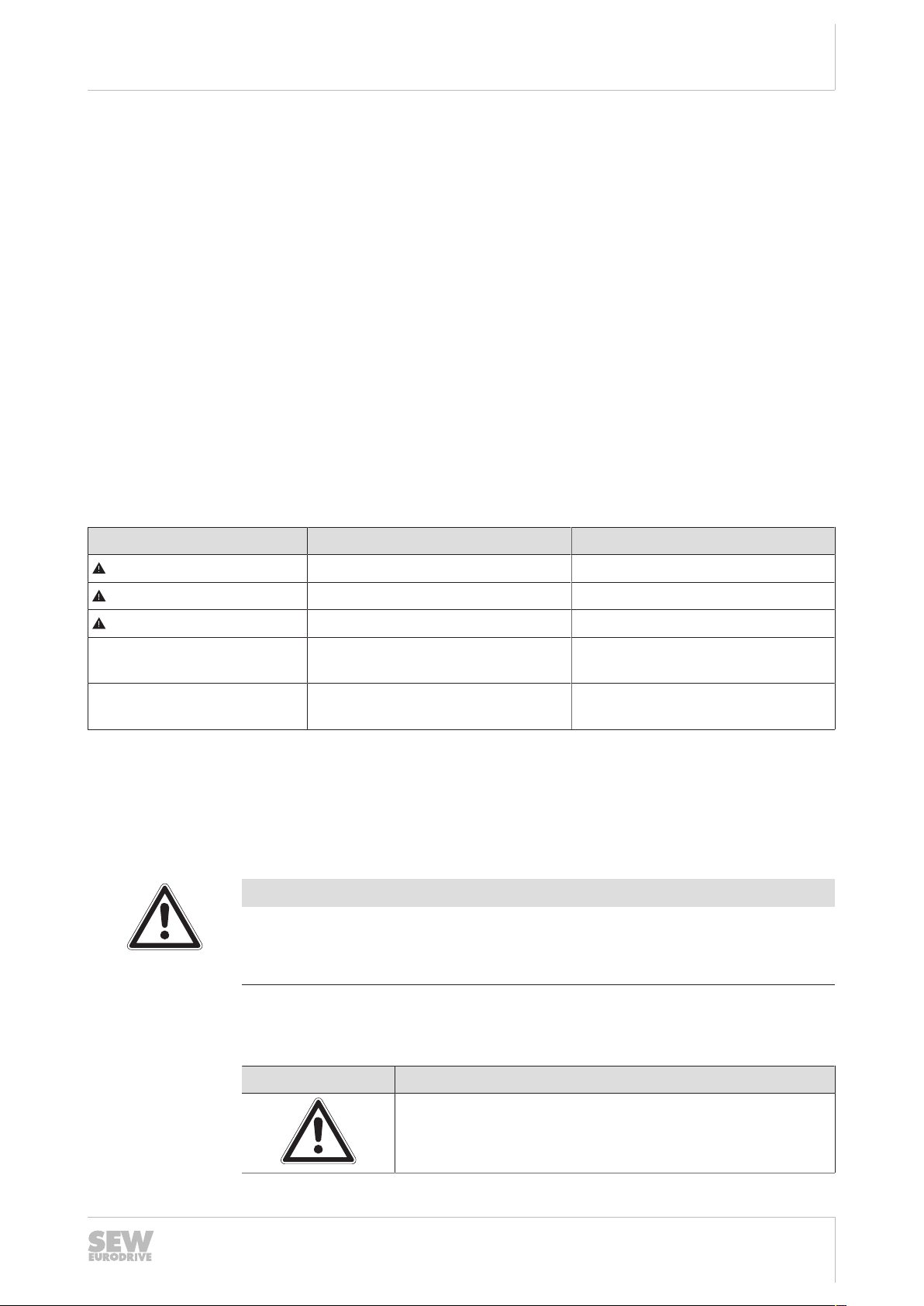
[5]
[4]
[1]
[3][2]
[6]
Operation
DOP operator panel
If the power supply of the vehicle is switched on, the DOP interface shows important
status information of the vehicle:
5
No. Meaning
[1] Currently selected part data
[2] Current position
[3] Current power rating of the vehicle
[4] Charging state of the battery
[5] Name of the vehicle
[6] Status and error messages
[7] Speed
Meaning of the background colors
The background colors have the following meaning:
Color Meaning
21228349067
• Address of the last successfully read transponder/data matrix code
• Distance (mm) that the vehicle travelled after the last position was read.
• Setpoint: Setpoint speed according to the settings in manual mode or automatic mode
• Actual: Current speed
• Limit: Maximum speed according to the settings in the safety controller
23507268/EN – 12/2017
Gray Software not ready.
No communication to the DOP operator panel.
Purple Timeout to higher-level controller
Green The vehicle is ready for operation.
Blue The vehicle has stopped at the target position in automatic mode.
Operating Instructions – Automated Guided Vehicle
31

Operation
[1]
[2]
[3][4][5]
DOP operator panel
5
5.6.2 Menu and navigation bar
Tap onto the initial screen to switch to the menu level. A window opens with the menu
and the navigation bar:
Color Meaning
Yellow The safety controller has stopped the vehicle (e.g. caused by
safety zone breach or emergency stop).
Red The vehicle is not ready to move due to a fault.
21283259915
No. Meaning
[1] Buttons to selected operating modes/functions
[2] The control elements in the navigation bar vary depending on the operating
level:
• On all levels:
Navigation buttons [3] and [5]
• Menu level (top level):
Language selection [4]
• Levels of the operating modes/functions (submenu):
Buttons for submenus (if available) and display of the current operating
mode/function
[3] Back to initial screen
[4] Select one of the following languages:
• English
• English
• French
[5] Back to the last operating level
32
Operating Instructions – Automated Guided Vehicle
23507268/EN – 12/2017

5.6.3 Automatic mode
[6]
[5]
[4]
[3]
[1]
[2]
In the "automatic mode" menu item, the following elements are available:
Operation
DOP operator panel
21286286603
5
Changing parameters
No. Meaning
[1] Information on the used program.
[2] Part data
[3] Current velocity
[4] Resume automatic mode
[5] To identify the position, the following values are displayed:
• Last transponder: Address of the last successfully read transponder/data
matrix code
• Distance: Distance (mm) that the vehicle travelled after the last position
was read.
[6] To change parameters, deactivate automatic mode, see chapter "Changing
parameters".
To change parameters, switch off automatic mode. The following procedure requires
the vehicle to remain at standstill after the automatic mode is switched off.
If the vehicle moves, changing parameters requires a special authorization (expert
mode) that is only granted to trained employees of SEW‑EURODRIVE and is therefore not described in this documentation.
1. Click the [Deactivate automatic mode] button.
ð The designation on the button changes to [Activate automatic mode]. The
vehicle stops.
23507268/EN – 12/2017
2. Click on the edit box of a parameter (e.g. Cmd).
ð A screen keyboard is displayed.
3. Enter a value. Apply the value using the enter key.
ð After the value has been changed successfully, the value "0" will be displayed
for the parameter "Cmd".
4. Reactivate the automatic mode.
Operating Instructions – Automated Guided Vehicle
33

Operation
[4]
[2]
[1]
[3]
[5]
DOP operator panel
5
5.6.4 Manual mode
In the "manual mode" menu item, the following elements are available:
9007219365621131
No. Meaning
[1] Select the track direction:
• CCW
• Straight forward
• CW
The selection must correspond to the track guidance ([2] or [4]) for the vehicle
to move in the desired direction of travel.
[2] Select the speed of the travel drive:
• Slow
• Fast
[3] Select the available track guidance (forwards):
• No track guidance: Vehicle travels without track guidance.
• Optical track guidance: Vehicle travels along an optical track.
[4] Specify the direction of travel of the travel drive:
• Turning (CCW/CW)
• Forward/reverse
[5] Select the available track guidance (backwards):
• No track guidance: Vehicle travels without track guidance.
• Optical track guidance: Vehicle travels along an optical track.
Executing travel commands
34
Operating Instructions – Automated Guided Vehicle
Proceed as follows:
1. Select the desired manual mode function.
ð Selected elements are highlighted in green on the software interface.
ð The multi-function button at the back of the vehicle flashes if you execute the
function by pushing the button (start and stop).
23507268/EN – 12/2017

ð The multi-function button is lit if you execute the function by continuously push-
[2]
[1]
ing the button.
2. Push the multi-function button (push and hold) to execute the travel command.
Measure when leaving track guidance
If the vehicle leaves track guidance unintentionally, proceed as follows:
ü Error number "110" displayed, background color is red.
ü The vehicle is in automatic mode.
1. Switch to manual mode.
2. Execute travel commands in manual mode to return to the track.
3. DANGER!
Switch to automatic mode.
ð The vehicle continues in automatic mode after a warning signal.
5.6.5 Diagnostics
Operation
DOP operator panel
5
In the "diagnostics" menu item, the following elements are available:
No. Meaning
[1] Button for selecting a submenu.
[2] Button for performing the following functions:
• Reset fault.
• Restarting the vehicle controller.
• Shut down the vehicle controller. DC24V supply is switched off.
9007219335920779
Meaning of the status LEDs
23507268/EN – 12/2017
The following table shows the meaning of the status LEDs if diagnostics information is
displayed:
Color Meaning
Gray No communication to the component.
Operating Instructions – Automated Guided Vehicle
35

Operation
[4]
[2]
[1]
[5]
[3]
DOP operator panel
5
Status
Color Meaning
Green Fault-free communication to component.
Red A fault occurred at the component.
In the "status" menu item, the following elements are available:
21284733963
No. Meaning
[1] Displays the active settings for track guidance
[2] Status code/fault code of the vehicle. For further information about the codes,
refer to the documentation of the devices.
[3] Displays the current status of the drives
[4] Displays the current status of the batteries
[5] Displays the current status for:
• Availability of MOVITRANS® (optional)
• Multi-function button
• UCS safety module
• Transponder read head
• EKK energy interface
36
Operating Instructions – Automated Guided Vehicle
23507268/EN – 12/2017

Position
[3]
[2]
[1]
[4]
In the "position" menu item, the following elements are available:
Operation
DOP operator panel
5
21284851083
No. Meaning
[1] Displays the relative position:
• Last transponder: Address of the last successfully read transponder/data
matrix code
• Distance: Distance (mm) that the vehicle travelled after the last position
was read.
[2] Displays the absolute position in directions X and Y, as well as the rotation of
the vehicle.
• Displays the single track ID
[3]
• Virtual track ID: No. of the virtual track the vehicle travels on.
[4] Displays the area:
• Area ID: Can be set to a defined position in automatic mode.
• Position in track: traveled distance from Area ID in mm
23507268/EN – 12/2017
Operating Instructions – Automated Guided Vehicle
37
Operation
[1]
[2]
[1] [2] [3] [4]
[7]
[5]
[6]
[8]
DOP operator panel
5
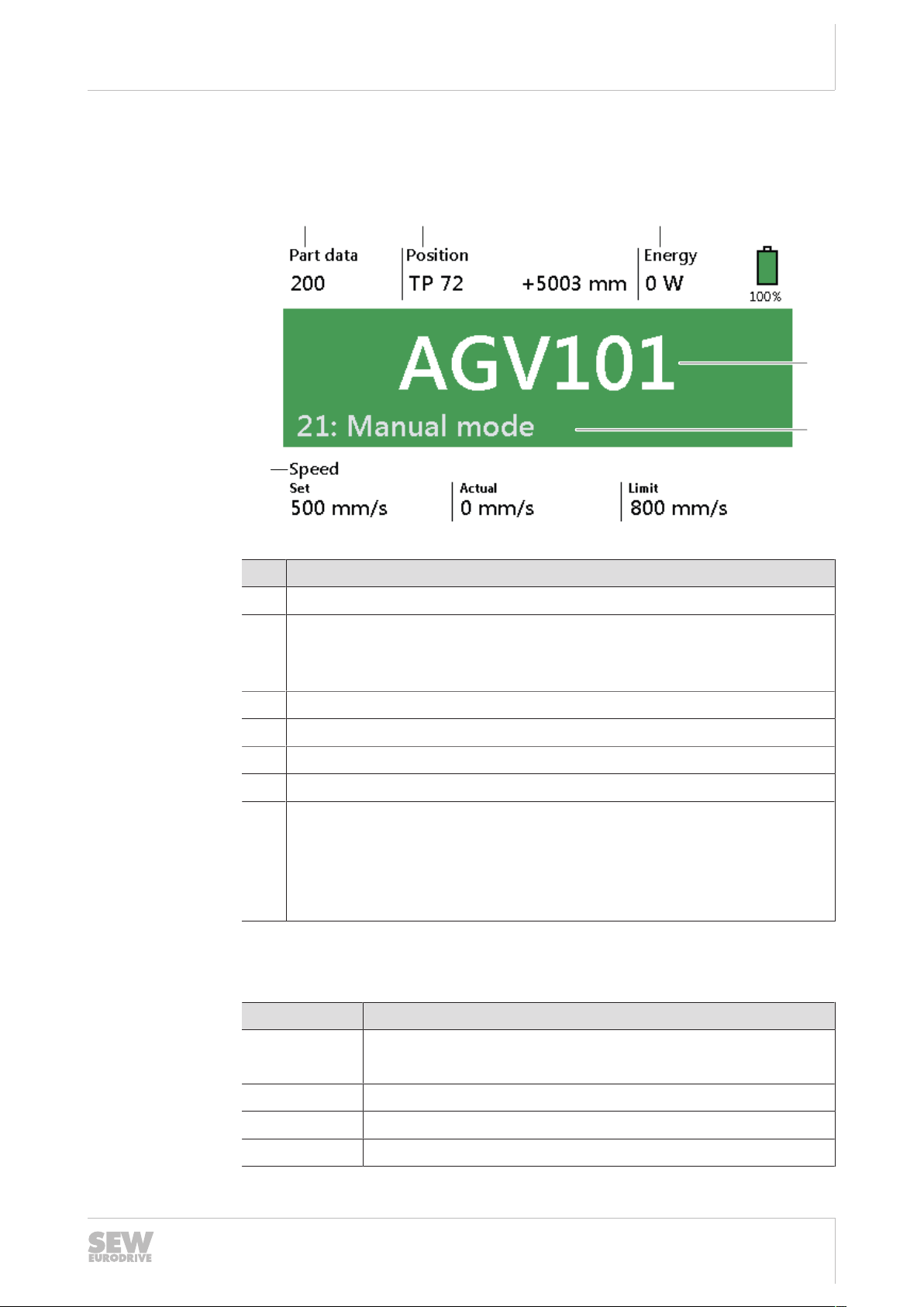
Version information
In the "Version information" menu item, the following elements are available:
No. Meaning
[1] Shows the used software products
[2] Software version
Safety
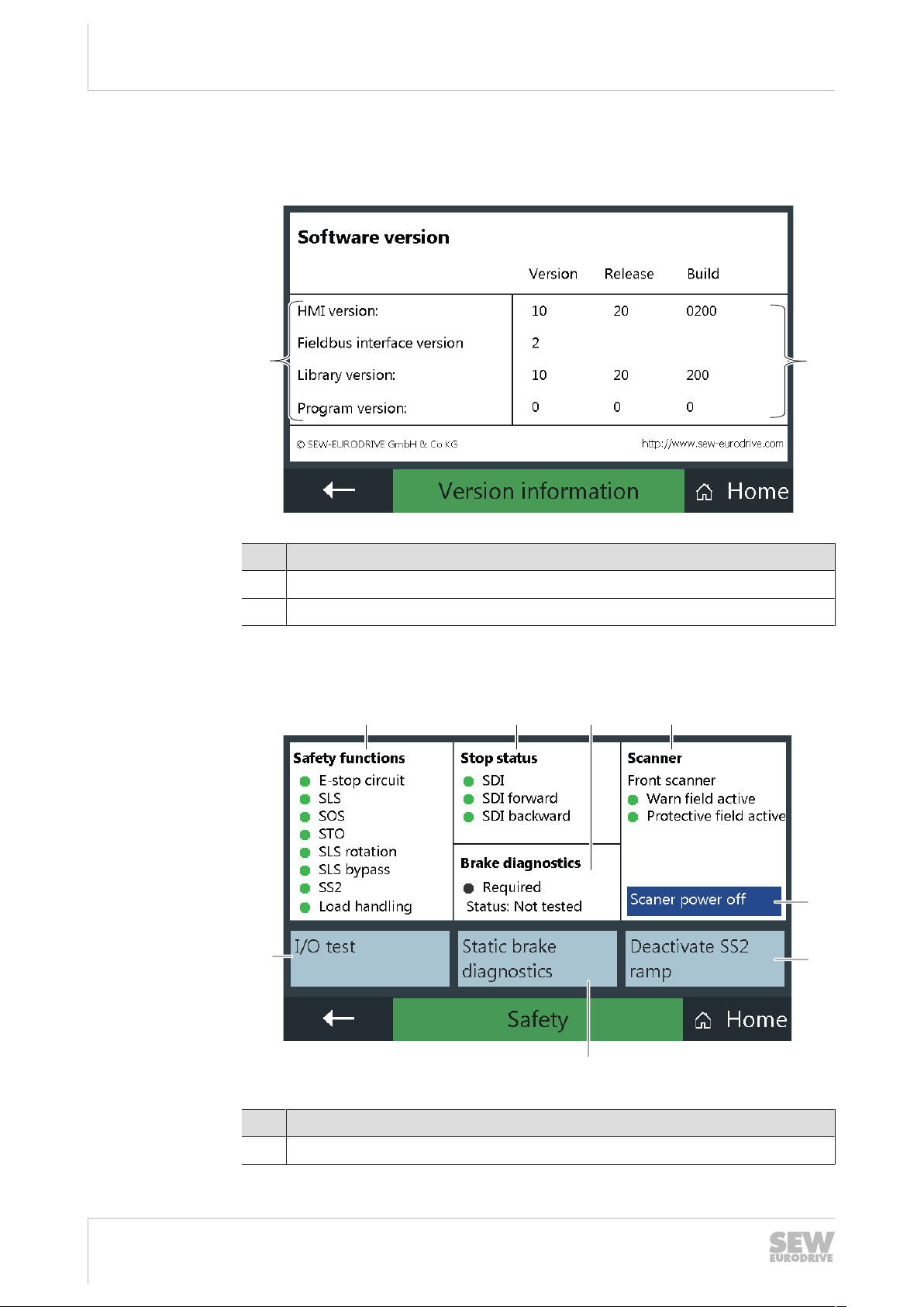
In the "Safety" menu item, the following elements are available:
21669909259
38
No. Meaning
[1] Displays the current status of the safety functions.
Operating Instructions – Automated Guided Vehicle
9007219329108107
23507268/EN – 12/2017

Operation
DOP operator panel
No. Meaning
[2] Displays the current status of the safety functions for stopping the vehicle in
hazardous situations.
[3] Displays if brake diagnostics is required:
• LED red: required.
• LED gray: not required.
Displays the current status of the brake diagnostics:
• Not tested
• OK
• Warning
• Failed
[4] Displays the current status of the safety laser scanner.
[5] Switch off scanner.
[6] Deactivate SS2 ramp.
This function is safety-relevant and may only be performed by qualified personnel (password-protected).
5
Brake diagnostics
[7] Start static brake diagnostics.
[8] Test inputs/outputs.
Brake diagnostics is started by the logic controller (project-specific deviations possible). Brake diagnostics is performed after every start and is repeated every 24hours.
If the brake diagnostics could not be performed in the defined time period or the test
was not passed, the travel speed of the vehicle is limited.
23507268/EN – 12/2017
Operating Instructions – Automated Guided Vehicle
39

Maintenance
Inspection and maintenance work
6
6 Maintenance
6.1 Inspection and maintenance work
6.1.1 Requirements
Qualification requirements
The work steps at the system solution described in the following chapters may only be
performed by trained and authorized employees.
For this reason, SEW‑EURODRIVE demands that the following minimum qualification
requirements are met, according to the roles of the employees:
Role Qualification Working
Operator Participation in the basic train-
ing(L1) for system operators, or
in the training for advanced system operators(L2):
• By specialist from
SEW‑EURODRIVE
• Or by maintenance personnel of the operator trained
by SEW‑EURODRIVE
Maintenance staff Participation at a training for
maintenance personnel taught
by SEW‑EURODRIVE specialist.
The system solution was installed and taken into operation by SEW‑EURODRIVE employees. Companies wanting to re-install or expand the system solution must first consult SEW‑EURODRIVE.
Types of inspection and maintenance work
The product includes components that require inspection and maintenance. This
chapter provides an overview of the following inspection and maintenance work:
• Inspection work
Work that may be performed by the operating personnel.
• Inspection and maintenance work
Work that may only be performed by service engineers.
If stationary components fail, they can be replaced independently by the relevant specialists. The vehicle may only be completely replaced. If you are not sure which components you can install by yourself, the staff of SEW‑EURODRIVE will be glad to help.
Simple inspection and maintenance work, that is usually performed daily.
All inspection and maintenance
work included in the training.
40
Keeping purchased parts in stock
Third-party components used in this project have deviating replacement and repair
times than standard components by SEW‑EURODRIVE. The operator is responsible
of keeping sufficient numbers of spare parts in stock.
23507268/EN – 12/2017
Operating Instructions – Automated Guided Vehicle

6.1.2 Inspection (operators)
The operator is responsible for the following inspection work:
1 day
Clean the vehicle cover.
Use teflon spray for dirt-repellent surfaces.
Check the caution signs at the vehicle for damages and dirt.
The safety notes attached to the vehicle must be complete and legible.
Check the operating and display elements for damages and dirt.
The check includes the following components:
• DOP operator terminal
• Buttons at the vehicle and carrier
Check the warning and safety devices for damages and dirt.
The check includes the following components:
• Safety laser scanner
• Safety switching strip (if installed)
• Emergency stop button
• LED lights
Maintenance
Inspection and maintenance work
6
Check the wheels for damage and wear.
The wheel lining is 22mm thick. If the lining is down to 19mm, replace the wheel.
Check the WLAN antenna for damages.
Defective WLAN antennas may cause communication problems.
Check the markings of the hazardous areas along the tracks.
Labels and markings on the floor must be complete, legible and visible.
Check the tracks for obstacles and remove them.
It is possible that work equipment (e.g. boxes or lifting carriages) were put down after
the operation has been interrupted.
Check if the tracks are clean.
Dirt on the tracks influences the travel/braking behavior.
Check if the track markings are clean and visible.
Dirty or damaged track markings influence the optical track guidance.
6.1.3 Inspection and maintenance (service engineers)
The service engineer performs the following inspection and maintenance works:
1 week
23507268/EN – 12/2017
Check the warning and safety devices for damages and dirt.
The check includes the following components:
• Safety laser scanner
• Safety switching strip (if installed)
• Emergency stop button
• LED lights
Operating Instructions – Automated Guided Vehicle
41

Maintenance
Inspection and maintenance work
6
1 week
Check if the vehicle is clean/contaminated and clean it.
Check the optical track for damages and replace it if necessary.
6months
Check the function of the safety devices and clean them.
The check and cleaning work includes the following components:
• Safety laser scanner
• Safety switching strip (if installed)
• Emergency stop button
• LED lights
Check the function of the sensors and clean them.
Check the drive wheels and auxiliary wheels for damage, such as pitting, cracks, or
wear. Check if the non-driven wheels run smoothly.
Visual inspection of motors and gear units.
6.1.4 Inspection and maintenance (SEW-EURODRIVE)
SEW‑EURODRIVE performs the following inspection and maintenance works:
1 year
Visually check the cabling and power supply chains (in drawer).
Clean the inside of the vehicle using a vacuum cleaner, and clean the electronic
components (using compressed air).
Inspection of entire drive: Check for running noise. Visual check of oil level.
Inspection of entire motor: Brake function and wear check. Check for running noise.
Clean the cooling air ducts.
Check the FS04 encoders for functional safety according to ENISO13849‑1.
Check the auxiliary wheels of the pivot bearings and lubricate them if necessary.
Check to see if the bearings and wheels run smoothly and for signs of wear. Replace
them if necessary.
Check the parameters/project data according to the project documentation.
Charge and discharge the batteries under supervision, then check the batteries.
Perform brake test on SS2 ramp.
3years
42
Replace auxiliary wheels (optional).
Replace drive wheels (optional).
Extensive maintenance of the travel drive: Replacing wear parts. Change the oil. Replace oil seal. Check the bearings for clearance and replace them if necessary.
23507268/EN – 12/2017
Operating Instructions – Automated Guided Vehicle

6.2 Failures
Fault Possible cause Measure
Oil leaking from vehicle. Gear unit leaking. Contact
SEW‑EURODRIVE.
Maintenance
Failures
6
Touching the vehicle or the
load carriers might result in
electrostatic discharge.
Unusual noises at the
vehicle during travel.
Vehicle stops on the travel
section.
Vehicle swings during
travel.
Vehicle does not move. Emergency stop not un-
Static charge of the vehicle
due to insufficient electrical
discharge capacity of the
floor.
Gear unit or travel drive defective.
Safety controller detects an
error.
Drive wheels are worn or
dirty.
• Insufficient traction of
the drive wheels.
• Wheels aligned incorrectly.
locked or reset.
• Improve the electrical
discharge capacity of
the floor.
• Install ESD protection.
• Contact
SEW‑EURODRIVE.
Contact
SEW‑EURODRIVE.
• Eliminate cause of error
(e.g. unlock emergency
stop button).
• Acknowledge the error
using the acknowledgment key.
Check and clean the drive
wheels.
Contact
SEW‑EURODRIVE.
Unlock the emergency
stop. Reset the emergency
stop.
6.2.1 Acknowledging faults
Faults that were triggered by an activated safety function can be acknowledged directly at the vehicle using the acknowledgment button (blue).
23507268/EN – 12/2017
• There is an obstacle in
the safety zone of the
safety laser scanner
(safety zone violation).
• The protection devices
of the load handling
device has tripped.
• Safety controller detects an error.
• Brake, swivel caster, or
drives defective.
• Remove the obstacle.
• Check the protection
devices of the load
handling device.
Contact
SEW‑EURODRIVE.
Operating Instructions – Automated Guided Vehicle
43

Maintenance
Status and error messages
6
The following table lists measures to acknowledge a failure at the vehicle:
State Control element Measure
Fault present. Acknowledgment button (blue):
lights up
Fault eliminated. Acknowledgment button (blue):
flashing at 1Hz
INFORMATION
Faults that cannot be acknowledged.
In case of faults on the vehicle that cannot be acknowledged, the acknowledgment
button is lit permanently, despite pressing it.
• Contact SEW‑EURODRIVE.
Faults that were not triggered by an activated safety function can be acknowledged at
the vehicle using the operator panel DOP.
6.3 Status and error messages
The system solution can display different error messages. This chapter offers help for
troubleshooting.
Codes and meaning of the faults and status are displayed on the initial screen of the
operator panel.
Eliminate fault.
Unlock the emergency stop
button if it has been pushed
during a failure.
Press the acknowledgment
button to acknowledge the
measure.
6.3.1 Status reports
Code Meaning Description
001 Vehicle travels. Vehicle executes travel command.
002 Initialization Vehicle controller reboots.
003 Standby The vehicle is in energy-saving mode.
004 Motion pending. The vehicle will start moving soon.
011 "Single track" occupied. The higher-level controller prevents a vehicle
012 In station The vehicle is at the target position.
(If the vehicle does not move, check on the initial screen if the speed setpoint and the speed
limit are set ≠"0".)
The vehicle movement can be started using
the multi-function button or by a travel command of the higher-level controller.
from entering a reserved area ("Single track").
The number of the transfer station is displayed
after the "/" character.
23507268/EN – 12/2017
44
Operating Instructions – Automated Guided Vehicle

Code Meaning Description
Maintenance
Status and error messages
6
013 Stop due to higher-level
controller.
014 Waiting for command. The vehicle is in automatic mode and waits for
021 Manual mode The vehicle is in manual mode.
022 Target transponder
reached.
023 Waiting for travel com-
mand.
6.3.2 Error messages
Code Meaning Possible cause Measure
091 Safety function The internal monitoring function
of the safety controller (UCS) has
tripped.
092 Emergency stop The vehicle was stopped by the
safety controller due to an actuated emergency stop button.
The vehicle is stopped by the higher-level controller.
a command.
The vehicle has reached the target position.
The vehicle is in automatic mode and waits for
a travel command.
Contact SEW‑EURODRIVE.
• Eliminate the cause of the
error.
• Unlock the emergency stop
button.
• Acknowledge the fault using
the acknowledgment button.
093 Obstacle on the track Safety laser scanner detected
safety zone violation because of
an obstacle.
099 Application error Error in program sequence.
The special error code is displayed after the "/" character.
100 Left drive The inverter of the left/right travel
101 Right drive
103 Optical sensor Device and communication error Contact SEW‑EURODRIVE.
106 Transponder reader Device and communication error Contact SEW‑EURODRIVE.
107 Safety controller Device and communication error
drive signals an error.
The special error code is displayed after the "/" character.
• Remove the obstacle.
• If the obstacle cannot be removed, deactivate the safety
laser scanner using the keyswitch.
Contact SEW‑EURODRIVE.
• Eliminate the fault as described in the documentation
of the drive.
• Reset the error by clicking the
[Reset] button on the initial
screen.
• Eliminate the fault as described in the documentation
of the safety controller.
• Acknowledge the fault in the
software.
23507268/EN – 12/2017
Operating Instructions – Automated Guided Vehicle
45

Maintenance
[1]
Replacing the battery
6
Code Meaning Possible cause Measure
110 Track not detected The selected track sensor does
not detect a track.
111 DC link too low
112 Transponder distance The read value of the transpon-
113 Position window The vehicle stops after a travel
114 Invalid track guidance The selected track sensor is no
115 Battery service life The battery is at the end of its
116 I/O module Device and communication error Contact SEW‑EURODRIVE.
• DC48V voltage supply interrupted.
• Energy storage unit discharged.
der distance does no longer
match the configured value.
command but the position is outside the position window.
longer available.
service life.
• Position the vehicle on the
track correctly.
• Select the correct track
sensor.
• Look for damages or dirt on
the optical track.
Contact SEW‑EURODRIVE.
Contact SEW‑EURODRIVE.
Contact SEW‑EURODRIVE.
Contact SEW‑EURODRIVE.
Contact SEW‑EURODRIVE.
117 Brake diagnostics re-
quired
6.4 Replacing the battery
Proceed as follows:
1. Move the vehicle to a suitable position away from the travel section, charging station, and MOVITRANS® line cables if present.
2. Switch off the vehicle.
3. Remove the screws on the cover plate of the vehicle.
The internal brake diagnostics
failed or is overdue.
Contact SEW‑EURODRIVE.
46
[1] Cover
Operating Instructions – Automated Guided Vehicle
9007220210067083
23507268/EN – 12/2017

4. Remove the cover plate of the vehicle.
[1]
[2] [2][2] [2]
[1] Fuse
[2] Battery
Maintenance
Replacing the battery
9007220212218507
6
5. Remove the fuses.
6. DANGER!Danger due to arcing. Severe injuries and damage to property. Disconnect the batteries in the correct sequence. Do not disconnect the cables from
the vehicle, but directly from the battery.
7. Disconnect the minus pole (blue) from the battery.
8. Disconnect the plus pole (red) from the battery.
9. Disconnect the wire jumpers between the batteries.
10. Remove the batteries.
11. Insert the new batteries.
12. Connect the wire jumpers between the batteries.
13. DANGER!Danger due to arcing. Severe injuries and damage to property. Connect the batteries in the correct sequence. Do not connect the cables to the
vehicle, but directly to the battery.
14. Connect the plus pole (red) to the battery.
15. Connect the minus pole (blue) to the battery.
16. Insert the fuses.
17. Place the cover plate onto the vehicle.
18. Screw the cover plate onto the vehicle.
19. Switch on the vehicle.
23507268/EN – 12/2017
Operating Instructions – Automated Guided Vehicle
47

Maintenance
[1]
[1]
[1]
[1]
Transport
6
6.5 Transport
WARNING
Hazard from suspended load.
Severe or fatal injuries.
• Do not stand under the load.
• Secure the area where loads can fall down.
• Use all lifting eyebolts.
• Align the lifting eyebolts with the direction of tension.
• Use adequately dimensioned lifting devices and lashing straps.
Proceed as follows:
Lifting the vehicle ü The vehicle is switched off.
1. Install the lifting eyebolts at the attachment points [1] on the cover plate, as shown
in the figure.
Wrapping the
vehicle
18014418711506187
2. Use the specified attachment points [1] to carry the load.
3. Select suitable lifting devices.
4. Lift the vehicle.
NOTICE
Damage to components at the vehicle frame (e.g. LED lights).
Damage to property.
• Place the vehicle on the wheels for transport.
• Make sure that the wheels carry the vehicle load. Components that are damaged
by the load are attached to the vehicle frame.
23507268/EN – 12/2017
48
Operating Instructions – Automated Guided Vehicle

5. Place the vehicle in the supplied transport box.
Maintenance
Spare parts
6
6. Secure the vehicle against rolling away.
6.6 Spare parts
Component Part number
Label "Do not ride on vehicle" 19112955
Label "CAUTION hand injuries" 19112998
Lifting eyebolt for attachment point 19085427
6.7 Electronics Service
Contact the SEW‑EURODRIVE Electronics Service in Bruchsal if a malfunction cannot
be rectified.
If you send the vehicle in for repair, provide the following information:
• Serial number (nameplate)
• Type designation
• Project number
• Brief description of the application
• Nature of the fault
• Accompanying circumstances
• Your own assumptions
23507268/EN – 12/2017
21457645067
Operating Instructions – Automated Guided Vehicle
49

Maintenance
Electronics Service
6
• Any unusual events preceding the problem, etc.
• Name of the affected vehicle
50
23507268/EN – 12/2017
Operating Instructions – Automated Guided Vehicle

7 Technical data
7.1 Ambient conditions
Data Value
Floor quality According to DIN18560 Floor screeds in
Floor leakage resistance <108Ω
Ambient temperature during operation +5–+40°C
Ambient temperature during storage +10–+40°C
Climate class according to EN60721‑3‑3 Class 3K3, no condensation
Vibration and shock load during operation According to EN61800-5-1
Technical data
Ambient conditions
building construction – Part 7: Heavy duty
floor screeds (industrial screeds)
7
7.2 Vehicle
Data Value
Dimensions (L×W×H) 845×600×305mm (without batteries)
Mass technology module without load 150kg
System voltages DC48V
For further information, refer to the vehicle nameplate.
7.2.1 Vehicle with energy module (55Ah)
Data Value
Dimensions (L×W×H) 845×600×415mm
Mass entire vehicle without load 225kg
Maximum payload 520kg
Electric charge 55Ah
Travel time without charging ≈ 4h
7.2.2 Vehicle with energy module (100Ah)
23507268/EN – 12/2017
Data Value
Dimensions (L×W×H) 845×600×535mm
Mass entire vehicle without load 320kg
Maximum payload 430kg
Electric charge 100Ah
Travel time without charging ≈ 8h
Operating Instructions – Automated Guided Vehicle
51

Technical data
Startup parameters
7
7.2.3 Vehicle with energy module (170Ah)
Data Value
Dimensions (L×W×H) 845×600×635mm
Mass entire vehicle without load 380kg
Maximum payload 370kg
Electric charge 170Ah
Travel time without charging ≈ 13h
7.3 Startup parameters
The following table lists the parameters for startup via the MOVITOOLS® MotionStudio
software:
Window Parameter Value
General settings Device type ELVCD
Kinematic model Center drive
Vehicle type 0
Remote IP Customer-specific IP ad-
dress of the logistics controller
Receiving port 51000
Timeout 1000ms
Travel axis scaling parameters
Monitoring/system limits Position window 100mm
Gear ratio i 21.98
Drive wheel diameter 200mm
Direction of rotation reversal right wheel
Direction of rotation reversal left wheel
Rapid stop deceleration 2000mm/s
Ramp set acceleration 250mm/s
Ramp set deceleration 700mm/s
Ramp set jerk 5000mm/s
Activated
Deactivated
2
2
2
3
52
Operating Instructions – Automated Guided Vehicle
Minimum radius 1000mm
Maximum speed forward 1400mm/s
Maximum speed reverse 180mm/s
Maximum speed turning 200mm/s
Maximum track gap 100mm
Maximum angle of rotation
for track scanning
45°
23507268/EN – 12/2017

Window Parameter Value
Technical data
Startup parameters
7
Maximum transponder spacing
Geometry/sensors Center distance 530mm
MOVITRANS® sensor front Deactivated
Distance from front sensor
to axis
MOVITRANS® sensor back Deactivated
Distance from rear sensor
to axis
Front optical sensor Activated
Reverse assembly Deactivated
Distance from sensor to
axis
Track color (move downwards)
Rear optical sensor Activated
Reverse assembly Activated
RFID sensor Activated
0mm (project-specific)
–
–
500 mm
Blue (RAL 5015)
Optional: red (RAL 3001)
Distance from sensor to
axis
Distance from sensor to
center
Energy management Drive lock when not active 10000ms
Number of energy interfaces
Safety technology UCS activated Active
Keyswitch speed 80mm/s
Warning zone speeds:
Field set 1 90mm/s
Field set 2 90mm/s
Field set 3 270mm/s
Field set 4 540mm/s
Ignore rear warning zone Deactivated
Brake diagnostics Brake diagnostics active Activated
Speed 300mm/s
Ramp set 1
0
0
None
23507268/EN – 12/2017
Standstill torque M0 of the
motor
Current I0 at standstill
torque M0
Operating Instructions – Automated Guided Vehicle
3.5Nm
32A
53

Technical data
Startup parameters
7
Window Parameter Value
Diagnostic mode Forwards/backwards
Test distance "Brake
opens"
Test time 2000ms
Test torque "Level 1" 2.4Nm
Test torque "Level 2" 2.4Nm
Maximum deviation 90°
50mm
54
23507268/EN – 12/2017
Operating Instructions – Automated Guided Vehicle

7.4 Dimension sheets
846
609 415
The following drawing shows the dimensions of the vehicle with 55 Ah battery capacity. The height of vehicles with other battery capacities varies as specified in the technical data.
Technical data
Dimension sheets
7
23507268/EN – 12/2017
9007219456721675
Operating Instructions – Automated Guided Vehicle
55

MAXOLUTION® Competence Center
8
8 MAXOLUTION® Competence Center
Germany
Bruchsal SEW-EURODRIVE GmbH & Co KG
Ernst-Blickle-Straße 42
76646 Bruchsal
Kirchheim SEW-EURODRIVE GmbH & Co KG
Domagkstraße 5
85551 Kirchheim (München)
Australia
Melbourne SEW-EURODRIVE PTY. LTD.
27 Beverage Drive
Tullamarine, Victoria 3043
Brazil
São Paulo SEW-EURODRIVE Brasil Ltda.
Estrada Municipal José Rubim, 205 – Rodovia Santos Dumont Km 49
Indaiatuba – 13347-510 – SP
China
Tianjin SEW-EURODRIVE (Tianjin) Co., Ltd.
No. 78, 13th Avenue, TEDA
Tianjin 300457
France
Hagenau SEW-USOCOME
48-54 route de Soufflenheim
B. P. 20185
67506 Haguenau Cedex
India
Chennai SEW-EURODRIVE India Private Limited
Plot No. K3/1, Sipcot Industrial Park Phase II
Mambakkam Village
Sriperumbudur - 602105
Kancheepuram Dist, Tamil Nadu
Italy
Solaro SEW-EURODRIVE di R. Blickle & Co.s.a.s.
Via Bernini,14
20020 Solaro (Milano)
Poland
Tychy SEW-EURODRIVE Polska Sp.z.o.o.
ul. Strzelecka 66
43-109 Tychy
South Africa
Johannesburg SEW-EURODRIVE (PROPRIETARY) LIMITED
Eurodrive House
Cnr. Adcock Ingram and Aerodrome Roads
Aeroton Ext. 2
Johannesburg 2013
P.O.Box 90004
Bertsham 2013
South Korea
Ansan SEW-EURODRIVE KOREA CO., LTD.
7, Dangjaengi-ro,
Danwon-gu,
Ansan-si, Gyeonggi-do, Zip 425-839
Tel. +49 7251 75-0
Fax +49 7251 75-1970
http://www.sew-eurodrive.de
maxolution@sew-eurodrive.de
Tel. +49 89 909552-10
Fax +49 89 909552-50
dtc-sued@sew-eurodrive.de
Tel. +61 3 9933-1000
Fax +61 3 9933-1003
http://www.sew-eurodrive.com.au
enquires@sew-eurodrive.com.au
Tel. +55 19 3835-8000
sew@sew.com.br
Tel. +86 22 25322612
Fax +86 22 25323273
http://www.sew-eurodrive.cn
info@sew-eurodrive.cn
Tel. +33 3 88 73 67 00
Fax +33 3 88 73 66 00
http://www.usocome.com
sew@usocome.com
Tel. +91 44 37188888
Fax +91 44 37188811
saleschennai@seweurodriveindia.com
Tel. +39 02 96 9801
Fax +39 02 96 79 97 81
http://www.sew-eurodrive.it
sewit@sew-eurodrive.it
Tel. +48 32 32 32 610
Fax +48 32 32 32 648
Tel. +27 11 248-7000
Fax +27 11 248-7289
http://www.sew.co.za
info@sew.co.za
Tel. +82 31 492-8051
Fax +82 31 492-8056
http://www.sew-eurodrive.kr
master.korea@sew-eurodrive.com
23507268/EN – 12/2017
56
Operating Instructions – Automated Guided Vehicle

Sweden
Jönköping SEW-EURODRIVE AB
Gnejsvägen 6-8
553 03 Jönköping
Box 3100 S-550 03 Jönköping
USA
Lyman SEW-EURODRIVE INC.
1295 Old Spartanburg Highway
P.O. Box 518
Lyman, S.C. 29365
MAXOLUTION® Competence Center
8
Tel. +46 36 34 42 00
Fax +46 36 34 42 80
http://www.sew-eurodrive.se
jonkoping@sew.se
Tel. +1 864 439-7537
Fax +1 864 439-7830
http://www.seweurodrive.com
cslyman@seweurodrive.com
23507268/EN – 12/2017
Operating Instructions – Automated Guided Vehicle
57


SEW-EURODRIVE—Driving the world
SEW-EURODRIVE GmbH & Co KG
Ernst-Blickle-Str. 42
76646 BRUCHSAL
GERMANY
Tel. +49 7251 75-0
Fax +49 7251 75-1970
sew@sew-eurodrive.com
www.sew-eurodrive.com
 Loading...