

SEW-Eurodrive MOVIDRIVE MDX60B, MOVIDRIVE MDX61B, INTERBUS DFI11B User Manual
MOVIDRIVE® MDX61B
Edition
INTERBUS DFI11B Fieldbus Interface
03/2004
Manual
1126 3717 / EN

SEW-EURODRIVE
1 Important Notes...................................................................................................... 4
2 Introduction ............................................................................................................ 5
3 Assembly / Installation Instructions..................................................................... 7
3.1 Installing the DFI11B option card................................................................... 7
3.2 Connection and terminal description of the DFI11B option............................ 9
3.3 Pin assignment ............................................................................................ 10
3.4 Shielding and routing bus cables................................................................. 11
3.5 Setting the DIP switches.............................................................................. 11
3.6 Display elements.......................................................................................... 14
I
00
4.1 Startup of the drive inverter.......................................................................... 16
4.2 Configuring the INTERBUS system............................................................. 18
4.3 Testing the PCP connection ........................................................................ 24
5 The PCP Interface................................................................................................. 26
5.1 Basic structure ............................................................................................. 26
5.2 PCP services ............................................................................................... 27
5.3 Parameters in the object list......................................................................... 29
5.4 Return codes for parameter setting.............................................................. 35
6 Application Examples.......................................................................................... 37
6.1 Control via process data ..............................................................................37
6.2 Setting parameters via the PCP interface.................................................... 37
6.3 Presentation of coding examples................................................................. 38
6.4 Process of a parameterization sequence..................................................... 38
6.5 Reading a drive parameter........................................................................... 39
6.6 Writing a drive parameter............................................................................. 40
4 Project Planning and Startup.............................................................................. 16
®
6.7 Writing IPOS variables/parameters via MOVILINK
6.8 Reading IPOS variables/parameters via MOVILINK
parameter channel.....41
®
parameter channel... 41
6.9 Writing IPOS variables/parameters using the download parameter block... 43
kVA
i
n
f
Hz
P
7 Technical Data...................................................................................................... 44
7.1 DFI11B option.............................................................................................. 44
8 Index...................................................................................................................... 45
Manual – MOVIDRIVE® MDX61B INTERBUS DFI11B Fieldbus Interface
3
1
Important Notes
1 Important Notes
Handbuch
• This manual does not replace the detailed operating instructions!
• Only electrical specialists are allowed to perform installation and startup
observing relevant accident prevention regulations and the MOVIDRIVE
MDX60B/61B operating instructions!
Documentation
Bus systems
• Read through this manual carefully before you start installation and startup of
MOVIDRIVE
• This manual assumes that the user has access to and is familiar with the
MOVIDRIVE
manual.
• In this manual, cross references are marked with "→". For example, (→ Sec. X.X)
means: Further information can be found in section X.X of this manual.
• A requirement of fault-free operation and fulfillment of any rights to claim under
guarantee is that you observe the information in the documentation.
General safety notes on bus systems:
This communication system allows you to adjust the MOVIDRIVE
specific application very accurately. As with all bus systems, there is a danger of
invisible, external (as far as the inverter is concerned) modifications to the parameters
which give rise to changes in the inverter’s behavior. This may result in unexpected (not
uncontrolled) system behavior.
®
drive inverters with the INTERBUS DFI11B option card.
®
documentation, in particular the MOVIDRIVE ® MDX60B/61B system
®
drive inverter to your
®
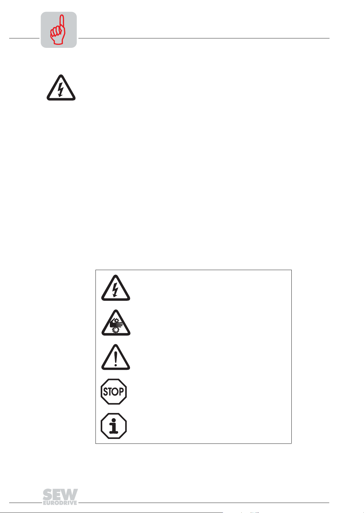
Safety and
warning notes
Always observe the safety and warning instructions in this publication!
Electrical hazard
Possible consequences: Severe or fatal injuries.
Hazard
Possible consequences: Severe or fatal injuries.
Hazardous situation
Possible consequences: Slight or minor injuries.
Harmful situation
Possible consequences: Damage to the unit and the
environment.
Tips and useful information.
4
Manual – MOVIDRIVE® MDX61B INTERBUS DFI11B Fieldbus Interface

2 Introduction
Introduction
2
Contents of this
manual
Additional
documentation
MOVIDRIVE® and
INTERBUS
This user manual describes how to install the INTERBUS DFI11B option card in the
MOVIDRIVE
INTERBUS fieldbus system.
It also contains an explanation of all settings on the fieldbus option card and connection
variants with INTERBUS in the form of small startup examples.
For a simple and effective connection of MOVIDRIVE® to the INTERBUS fieldbus
system, you should request the following publications from SEW-EURODRIVE about
the fieldbus technology in addition to this manual:
•MOVIDRIVE
•MOVIDRIVE
The manual for the MOVIDRIVE
and their coding. It also explains the whole range of control concepts and application
options in the form of small examples.
The parameter list is a list of all drive inverter parameters that can be read and written
via various communication interfaces such as RS-485, SBus and even the fieldbus
interface.
The MOVIDRIVE® drive inverter together with the DFI11B option and its highperformance universal fieldbus interface enable the connection to master
programmable controllers via the open and standardized INTERBUS fieldbus system.
®
MDX61B drive inverter and how to start up MOVIDRIVE® with the
®
Fieldbus Unit Profile manual
®
MDX60/61B system manual
®
fieldbus unit profile describes the fieldbus parameters
Unit profile
Drive parameters
READ/WRITE
The performance of the inverter (also referred to as the unit profile) that forms the basis
for INTERBUS operation, is fieldbus-independent and, therefore, uniform. This allows
the user to develop fieldbus-independent drive applications. This makes it much easier
to change to other bus systems, such as PROFIBUS (DFP 21B option) or DeviceNet
(DFD 21B option).
MOVIDRIVE® offers digital access to all drive parameters and functions via the
INTERBUS interface. The drive inverter is controlled via the fast, cyclical process data.
This process data channel offers the opportunity to initiate various drive functions such
as enable, controller inhibit, normal stop, rapid stop, and to specify setpoint values such
as setpoint speed, integrator time for acceleration/ramp down.
At the same time you can also use this channel to read back actual values from the drive
inverter, such as actual speed, current, unit status, fault number or reference signals.
While the process data exchange generally occurs cyclically, the drive parameters can
be read or written only acyclically via the READ and WRITE services. This parameter
data exchange enables you to implement applications in which all the important drive
parameters are stored in the master programmable controller, so that there is no need
to make manual parameter settings on the drive inverter itself.
Manual – MOVIDRIVE® MDX61B INTERBUS DFI11B Fieldbus Interface
5
2
Introduction
Startup
Monitoring
functions
Diagnostics
Generally, the INTERBUS DFI11B option card has been designed so that all
INTERBUS-specific settings, such as process data length and baud rate can be made
using the hardware switch on the option card. This manual setting means the drive
inverter can be integrated into the INTERBUS system and switched on quickly.
The parameter setting process can be performed automatically by the higher-level
INTERBUS master (parameter download). This forward-looking variant shortens the
system startup time and simplifies the documentation of your application program
because all the important drive parameters can now be stored directly in your control
program.
The use of a fieldbus system requires additional drive system monitoring such as time
monitoring of the fieldbus (fieldbus timeout) or even special emergency stop concepts.
The MOVIDRIVE
®
monitoring functions can be customized to your application. You can
determine, for instance, which of the drive inverter’s fault responses should be triggered
in the event of a bus error. A rapid stop is useful for many applications, although this can
also be achieved by 'freezing' the last setpoint values so the drive continues operating
with the most recently valid setpoint values (for example, conveyor belt). As the
functions of the control terminals are still active in fieldbus operation, you can still
implement fieldbus-independent emergency stop concepts via the terminals of the drive
inverter.
The MOVIDRIVE® drive inverter offers numerous diagnostic options for startup and
service.
For example, you can use the integrated fieldbus monitor to control both setpoint values
sent from the higher-level controller as well as the actual values. The MOVITOOLS
software package offers a convenient diagnostic option that allows for a detailed display
of fieldbus and device state information in addition to the settings of all drive parameters
(including fieldbus parameters).
®
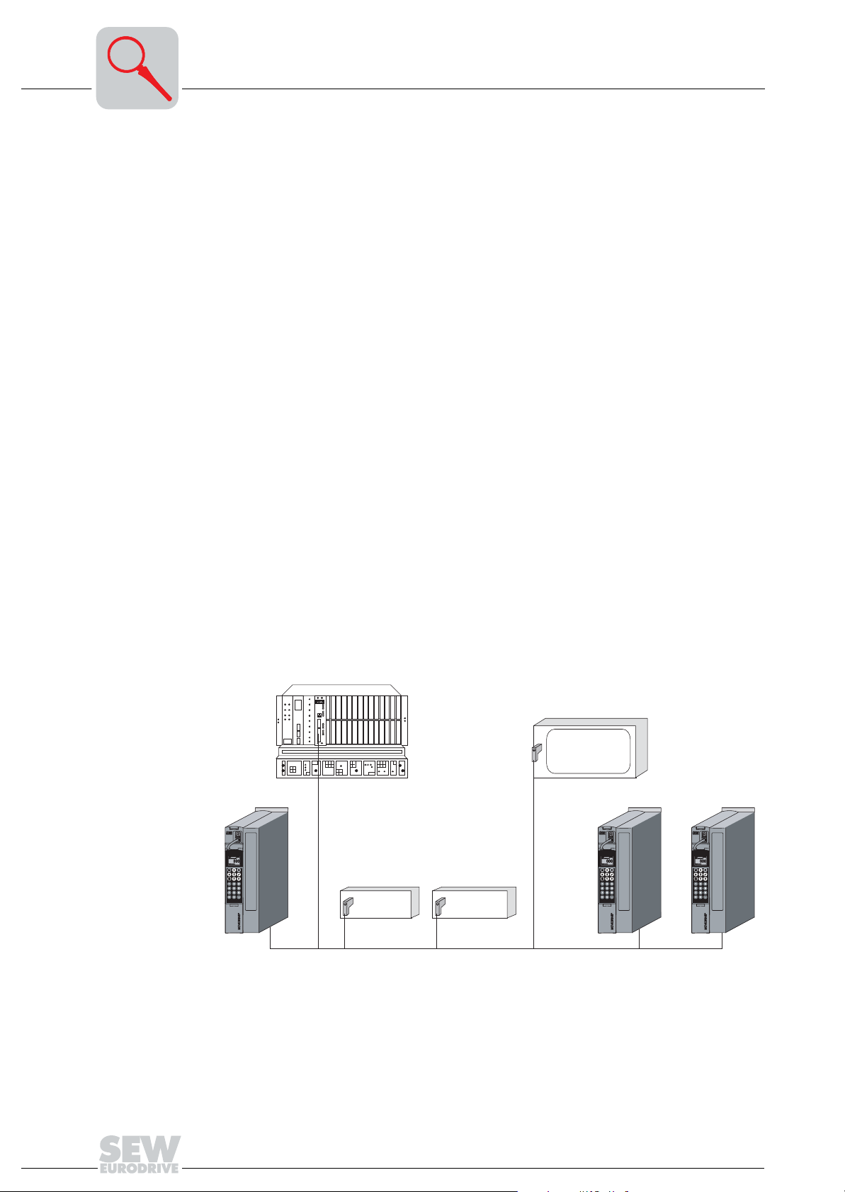
[1]
INTERBUS Master
Digital I/O Analog I/O
INTERBUS
Figure 1: INTERBUS with MOVIDRIVE® MDX61B
6
Manual – MOVIDRIVE® MDX61B INTERBUS DFI11B Fieldbus Interface
53568AXX

Assembly / Installation Instructions
Installing the DFI11B option card
3 Assembly / Installation Instructions
3.1 Installing the DFI11B option card
• Option cards can only be installed and removed for MOVIDRIVE® MDX61B
sizes 1 to 6.
• Only SEW-EURODRIVE engineers can install or remove option cards for
MOVIDRIVE
®
MDX61B size 0.
3
Before you begin
The DFI11B option card must be plugged into the fieldbus slot.
Observe the following notes before installing or removing an option card:
• De-energize the inverter. Switch off the DC 24 V and the supply voltage.
• Take appropriate measures to protect the option card from electrostatic charge (use
discharge strap, conductive shoes, etc.) before touching it.
• Before installing the option card, remove the keypad and the front cover.
• After installing the option card, replace the front cover and the keypad.
• Keep the option card in its original packaging. Do not remove the option card from
the packaging until immediately before you are ready to install it.
• Hold the option card by its edges only. Do not touch any components.
Manual – MOVIDRIVE® MDX61B INTERBUS DFI11B Fieldbus Interface
7
3
Installing and
removing the
option card
Assembly / Installation Instructions
Installing the DFI11B option card
2.
1.
3.
4.
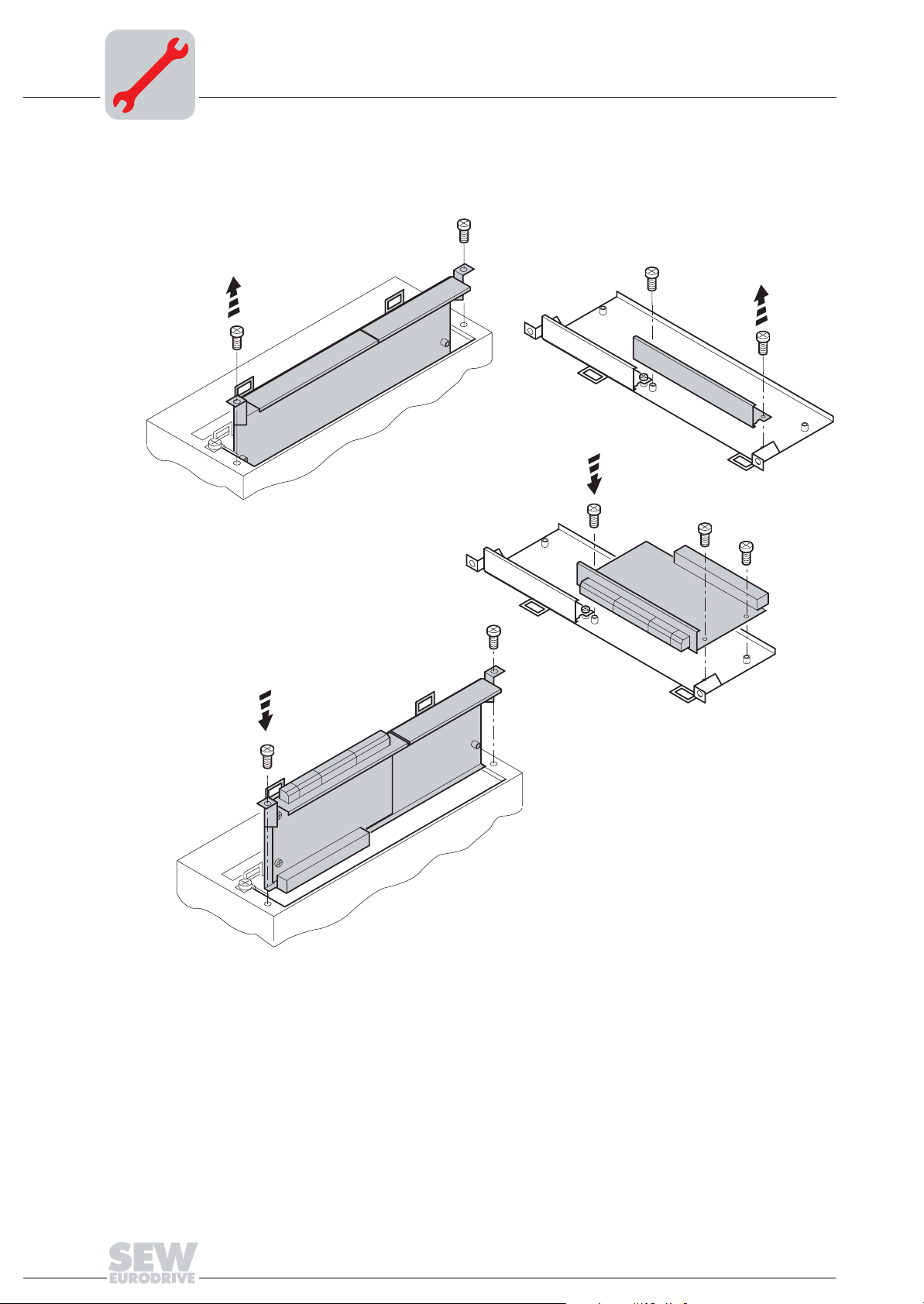
Figure 2: Installing an option card in MOVIDRIVE® MDX61B sizes 1 to 6
1. Remove the two retaining screws holding the card retaining bracket. Evenly pull the
card retaining bracket out from the slot (do not twist!).
2. Remove the two retaining screws of the black cover plate on the card retaining
bracket. Remove the black cover plate.
3. Position the option card onto the retaining bracket so that the three retaining screws
fit into the corresponding holes on the card retaining bracket.
4. Insert the retaining bracket with installed option card into the slot, pressing slightly so
it is seated properly. Secure the card retaining bracket with the two retaining screws.
5. To remove the option card, follow the instructions in reverse order.
53001AXX
8
Manual – MOVIDRIVE® MDX61B INTERBUS DFI11B Fieldbus Interface
Assembly / Installation Instructions
Connection and terminal description of the DFI11B option
3.2 Connection and terminal description of the DFI11B option
3
Part number
Front view of
DFI11B
DFI 11B
01
0
2
1
2
2
2
1
22M4
0,5M
U
L
RC
BA
RD
TR
X30X31
INTERBUS interface type DFI11B option: 824 309 3
The "INTERBUS interface type DFI11B" option is only possible in conjunction with
MOVIDRIVE
®
MDX61B, not with MDX60B.
The DFI11B option must be plugged into the fieldbus slot.
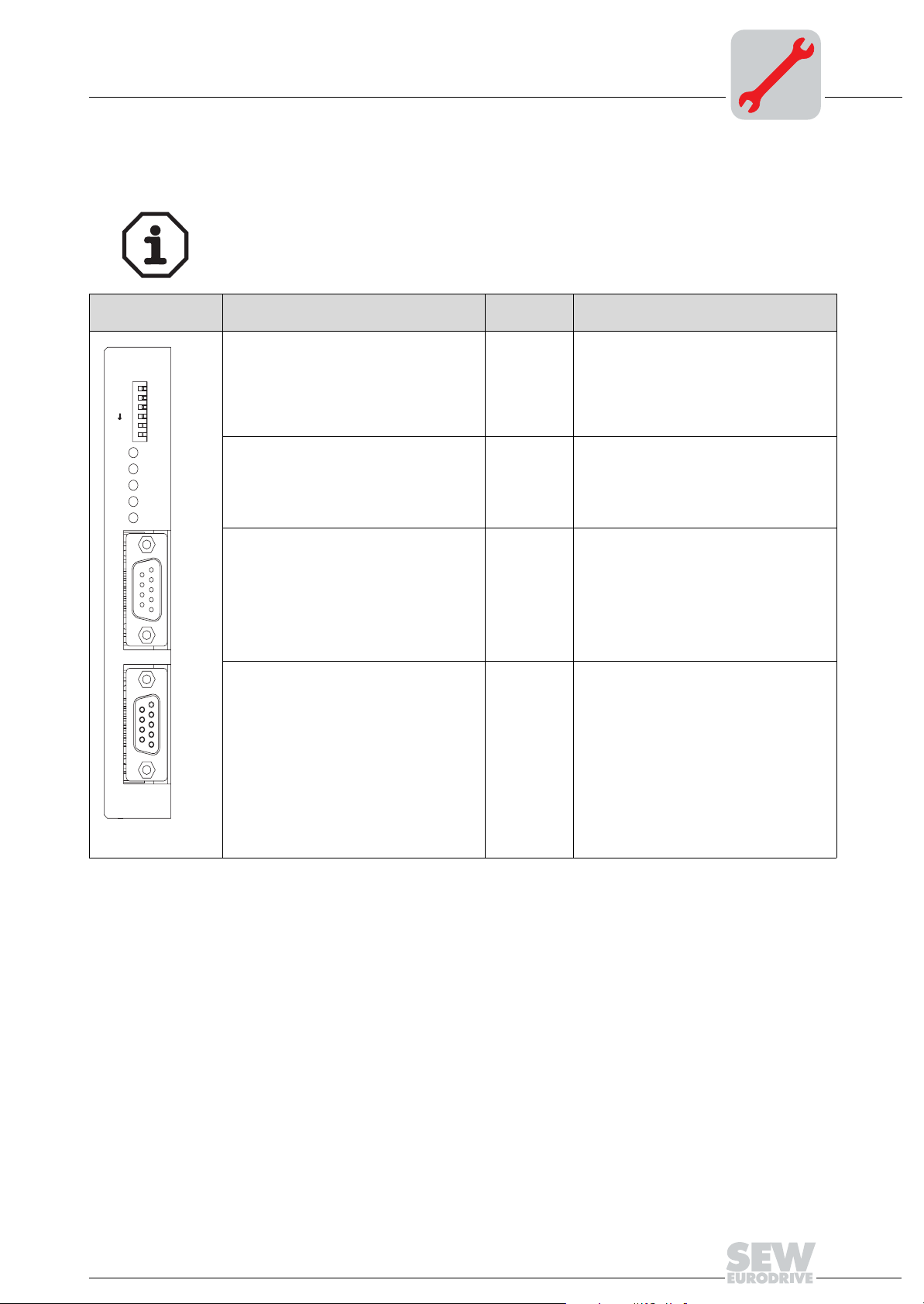
Description
Six (6) DIP switches for setting the
process data length, PCP length and baud
rate
U
= Logic voltage (green = OK)
L
RC = Remote cable check (green = OK)
BA = Bus active (green = OK)
RD = Remote bus disabled (orange = OK)
TR = Transmit (green = PCP active)
X30: INTERBUS interface
incoming
X31: INTERBUS interface
outgoing
DIP switch
Terminal
0
2
2
, 21, 2
1, 2, 4
2M / 0,5M
X30:1
X30:2
X30:3
X30:4
X30:5
X30:6
X30:7
X30:8
X30:9
X31:1
X31:2
X31:3
X31:4
X31:5
X31:6
X31:7
X31:8
X31:9
Function
Number of process data (1 to 6 words)
Number of PCP words (1, 2 or 4 words)
Baud rate:
0 = 2 MBaud
1 = 0.5 MBaud
The INTERBUS LEDs display the current
status of the fieldbus interface and the
INTERBUS system:
DO
DI
COM
N.C.
N.C.
/DO
/DI
N.C.
N.C.
DO
DI
COM
N.C.
Jumper to X31:9
/DO
/DI
N.C.
Jumper to X31:5
52287AXX
Manual – MOVIDRIVE® MDX61B INTERBUS DFI11B Fieldbus Interface
9
3
3.3 Pin assignment
Assembly / Installation Instructions
Pin assignment
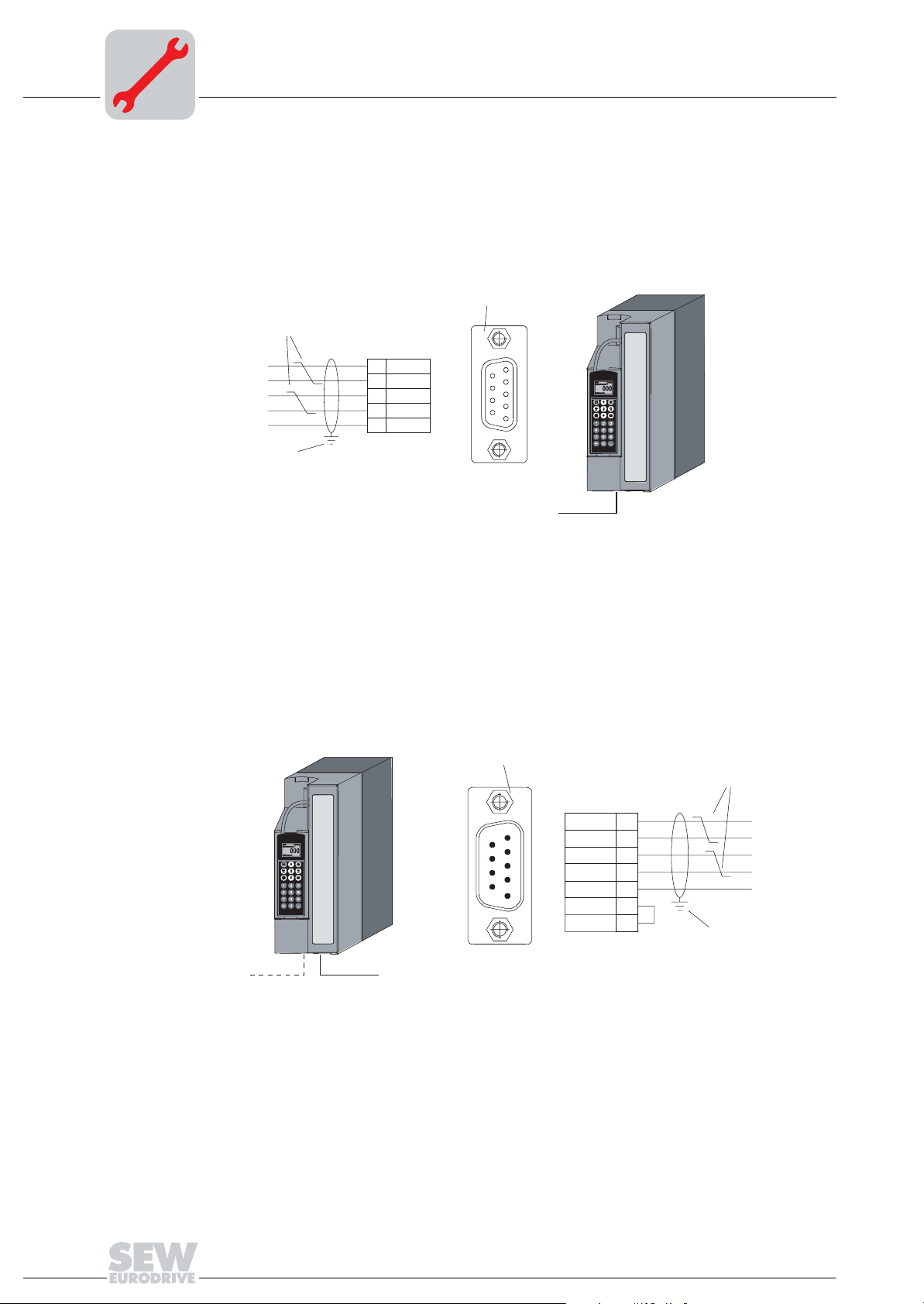
Connection to the INTERBUS network is realized using a 9-pin sub D coupling for the
incoming remote bus and a 9-pin sub D plug for the outgoing remote bus according to
IEC 61158. The following figures show the connection assignment of the 9-pole Sub D
coupling/plug for the incoming and outgoing remote bus as well as the signal wire colors
of the bus cable used for the INTERBUS.
[1]
[2]
GN
YE
PK
GY
BN
[3]
6
/DO
1
DO
7
/DI
2
DI
3
COM
5
691
52296AXX
Figure 3: Assignment of 9-pin sub D coupling of the incoming remote bus cable
GN = Green BN = Brown
YE = Yellow [1] 9-pin sub D coupling
PK = Pink [2] Signal cable, twisted
GY = Gray [3] Conductive, wide area connection is necessary between the
plug housing and the shield
[1]
[2]
10
6
1
6
9
5
/DO
DO
/DI
DI
COM
1
7
2
3
5
9
GN
YE
PK
GY
BN
[3]
52297AXX
Figure 4: Assignment of 9-pin sub D plug of the outgoing remote bus cable
GN = Green BN = Brown
YE = Yellow [1] 9-pole sub D connector
PK = Pink [2] Signal line, twisted
GY = Gray [3] Conductive, wide area connection is necessary between the
plug housing and the shield
As a rule, the DFI11B option is connected to the INTERBUS system using the 2-wire
remote bus with a 6-core shielded cable with twisted signal wire pairs.
Manual – MOVIDRIVE® MDX61B INTERBUS DFI11B Fieldbus Interface
Assembly / Installation Instructions
The 2-wire remote bus chiefly comprises an RS-485 data out channel (signal wires "DO"
and "/DO") and the RS-485 data in channel (signal wires "DI" and "/DI").
3.4 Shielding and routing bus cables
The INTERBUS interface DFI11B supports RS-485 transmission technology and requires the cable type A to IEC 61158 specified as the physical medium for INTERBUS.
This cable must be a 6-core shielded and twisted pair cable.
Correct shielding of the bus cable attenuates electrical interference that may occur in
industrial environments. The following measures ensure the best possible shielding:
• Tighten the mounting screws on the connectors, modules and equipotential bonding
conductors by hand.
• Only use connectors with a metal housing or a metallized housing.
• Connect the shielding in the connector with the greatest possible surface area.
• Attach the shielding of the bus line on both sides.
• Do not route signal and bus cables parallel to power cables (motor leads). They must
be routed in separate cable ducts.
• Use metallic, grounded cable racks in industrial environments.
• Route the signal cable and the corresponding equipotential bonding in close proximity using the shortest way possible.
• Avoid using plug connectors to extend bus cables.
• Route the bus cables closely along existing grounding surfaces.
Shielding and routing bus cables
3
In case of fluctuations in the earth potential, a compensating current may flow via the
bilaterally connected shield that is also connected to the protective earth (PE). Make
sure you supply adequate equipotential bonding according to relevant VDE regulations
in such a case.
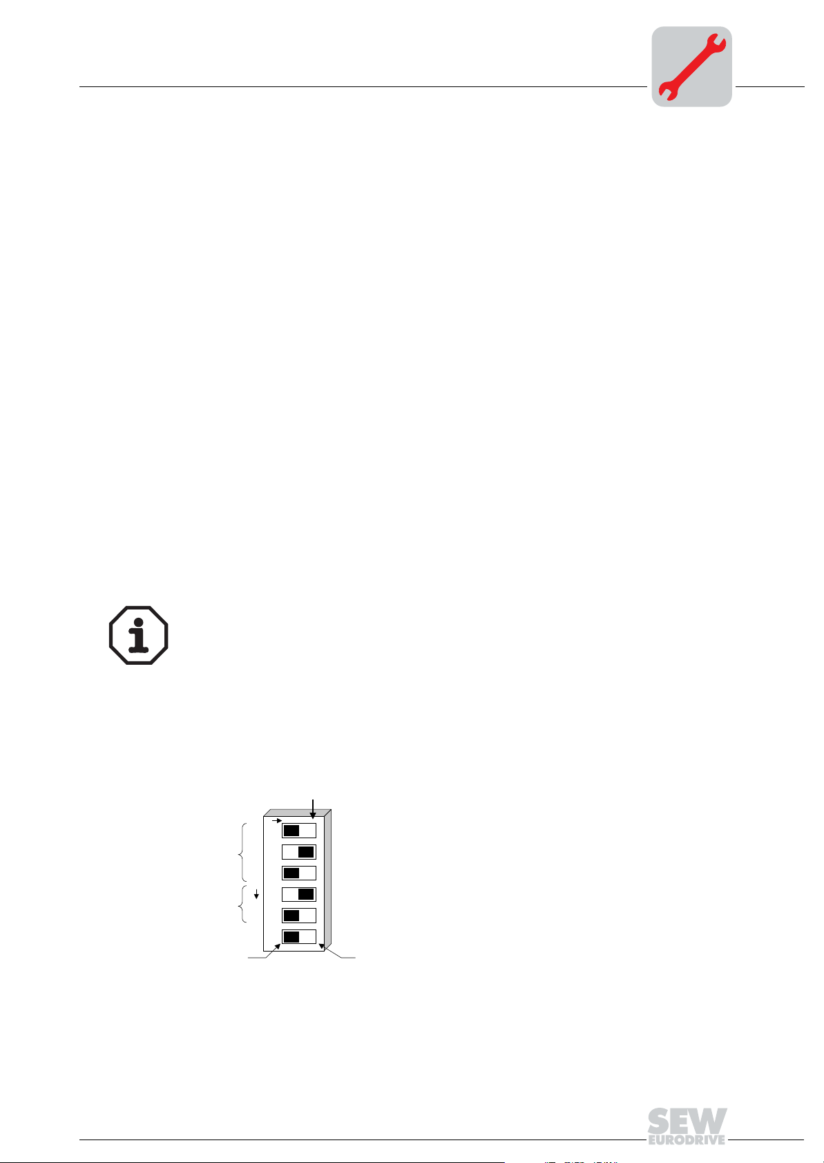
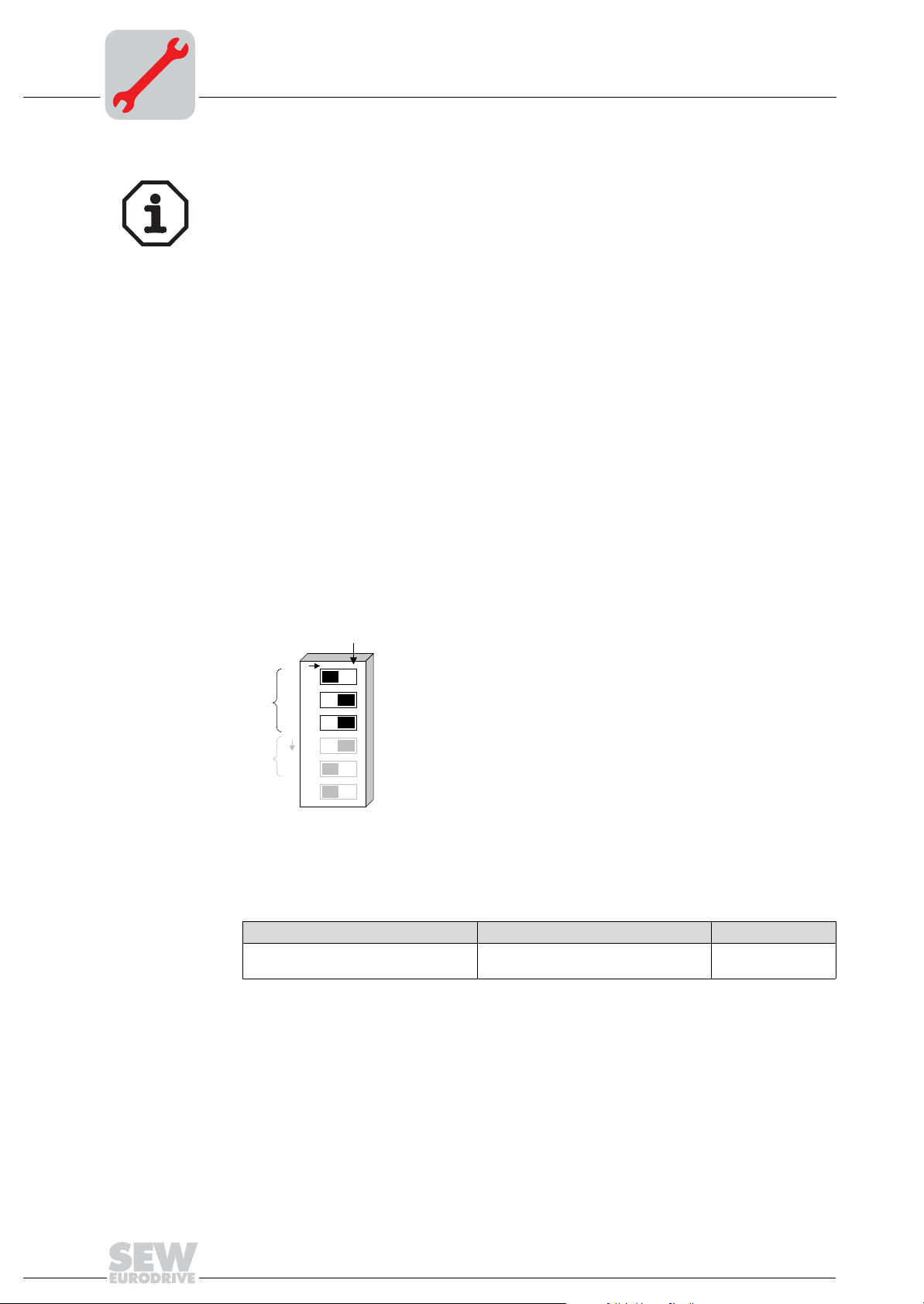
3.5 Setting the DIP switches
The six DIP switches S1 to S6 on the front side of the option are used for setting the
process data length, the PCP length and for selecting the baud rate.
ON
ON
1234
0
2
1
2
[1]
2
2
[2]
DIP switch assignment for DFI11B
[3]
56
PAC ER
2M
0.5M
1
42
[4]
03700AXX
[1] Number of process data (1 to 6 words)
[2] Number of PCP words (1, 2 or 4 words)
Baud rate: [3] OFF: 2 MBaud / [4] ON: 0.5 Mbaud
Setting shown in the figure:
Process data width: 2 PD
Number of PCP words: 1 PCP
Baud rate: 2 Mbaud
Manual – MOVIDRIVE® MDX61B INTERBUS DFI11B Fieldbus Interface
11
3
Assembly / Installation Instructions
Setting the DIP switches
Note
De-energize the drive inverter (mains and 24 V backup supply) every time before you
change the DIP switch settings. The settings of DIP switches S1-1 to S1-5 only become
effective during initialization of the drive inverter.
The drive inverter signals the "Microprocessor not ready" ID code (38 hex) if the DIP
switch settings are incorrect.
Setting the baud
rate
Setting the process data and
PCP length
The baud rate is selected using DIP switch S1-6. The selected baud rate takes effect
immediately and might therefore interrupt an existing data communication of the Interbus.
Up to six INTERBUS data words can be exchanged between the INTERBUS interface
and the DFI11B. These data words can be divided between the process data channel
and the PCP channel using DIP switches S1-1 to S1-5. Because of the restriction to six
data words, some settings cannot be reproduced on the Interbus.
The DFI11 signals the "Microprocessor not ready" ID code (38hex) if the setting is incorrect. The incorrect setting is indicated by the red TR LED. The following figure shows
the peripheral conditions for setting the process data and PCP lengths. The following
restrictions apply:
ON
ON
1234
0
2
1
6PD
2
2
2
[A]
56
PAC ER
1
42
12
2M
0.5M
ID: 03hex (3dez)
Figure 5: Settings for operating the DFI11B with 6 process data
[A]PCP setting ineffective!
Process data length in words PCP length ID code
6 PCP setting ineffective;
no PCP channel can be used
Manual – MOVIDRIVE® MDX61B INTERBUS DFI11B Fieldbus Interface
03hex (3dec)
03701AXX

Assembly / Installation Instructions
Setting the DIP switches
3
max.
5 DP
0 PCP
O
N
1
0
2
2
1
2
3
2
2
4
5
P
A
C
E
6
R
2M
ID: 38 hex (56 dez)
ON
0.5M
ON
O
N
1
0
2
max.
5 DP
1
1 PCP
42
2
1
2
3
2
2
4
5
P
A
C
E
6
R
0.5M
2M
max.
4 DP
1
2 PCP
42
ID: E3 hex (227 dez)
O
N
0
2
1
2
2
2
P
A
C
E
R
ID: E0 hex (224 dez)
ON
1
2
3
4
5
6
0.5M
2M
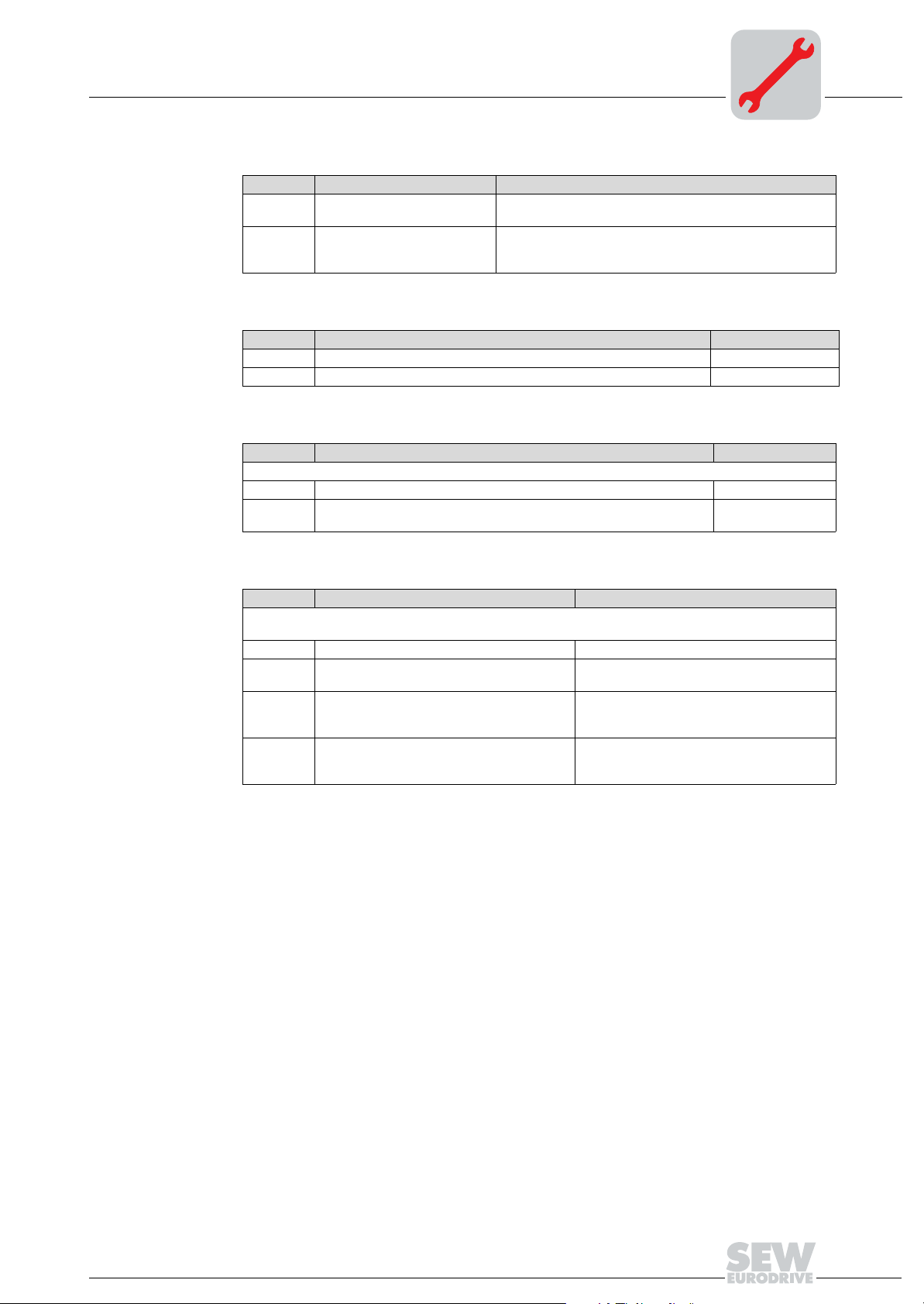
Figure 6: Examples for setting the PCP length and the maximum process data length
PCP length Maximum process data length ID code
1 word 5 words E3 hex (227dec)
2 words 4 words E0 hex (224dec)
4 words 2 words E1 hex (225dec)
If the max. length is exceeded or the setting is 0 or 7 PD
38 hex (56dec) = "Microprocessor not
ready"
All settings that have not been mentioned result in the "Microprocessor not ready" ID
code. The inverter then signals 0PD in parameter P090 "PD configuration" and indicates
that the setting is incorrect by means of the red TR LED on the DFI11B option card.
ON
O
N
1
0
2
max.
2 DP
1
4 PCP
42
2
1
2
3
2
2
4
5
P
A
C
E
6
R
2M
1
42
0.5M
ID: E1 hex (225 dez)
53597AXX
Manual – MOVIDRIVE® MDX61B INTERBUS DFI11B Fieldbus Interface
13
3
3.6 Display elements
Assembly / Installation Instructions
Display elements
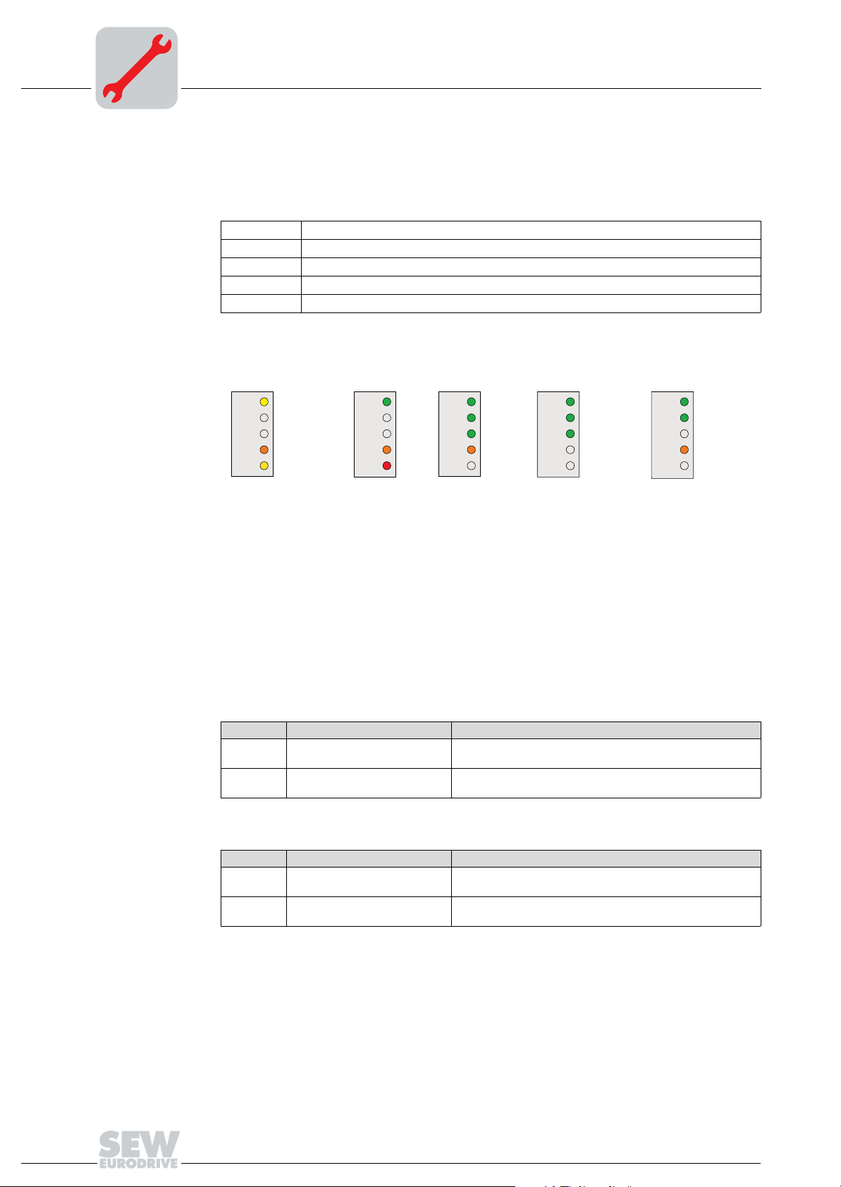
INTERBUS LEDs
The INTERBUS interface DFI11B option card has five LEDs for diagnosing the INTERBUS system. These LEDs indicate the current status of the DFI1B and the INTERBUS
system.
U
L
RC Remote Cable Check (green = OK)
BA Bus Active (green = OK)
RD Remote Bus Disabled (red = OFF)
TR Transmit (green = PCP active)
Logic Voltage (green = OK)
The following figure shows frequently occurring LED patterns of the diagnostic LEDs.
The following tables provide a detailed description of the LEDs.
yellow
U
L
OFF
RC
OFF
BA
orange
RD
yellow flash, OFF
TR TR TR TRTR
U
RC
BA
RD
green
L
U
OFF
RC
OFF
BA
orange
RD
red OFF OFFOFF / PCP: green
green
L
green
green flash
orange
U
RC
BA
RD
green
L
green
green
OFF
U
CC
BA
RD
green
L
green flash
OFF
orange
[A] [B] [C] [D] [E]
Figure 7: Frequently occurring LED patterns
06515AEN
[A] Inverter power-on (INTERBUS not yet active)
[B] Incorrect DIP switch setting (INTERBUS not yet active)
[C] Initialization phase of the INTERBUS system
[D] Correct INTERBUS operation
[E] Incorrectly set baud rate
LED UL "U Logic"
(green)
LED RC "Remote
Cable Check"
(green)
State Meaning Fault correction
On Supply voltage applied to bus
electronics
Off Supply voltage for bus
electronics missing
State Meaning Fault correction
On Incoming remote bus
connection OK
Off Incoming remote bus
connection not OK
-
Check that the connection unit is correctly seated and the
DC 24 V voltage supply for the inverter is present.
-
Check the incoming FO remote bus.
14
Manual – MOVIDRIVE® MDX61B INTERBUS DFI11B Fieldbus Interface
LED BA "Bus
Active" (green)
LED RD "Remote
Bus Disable" (red)
LED TR "Transmit" (green)
Assembly / Installation Instructions
Display elements
State Meaning Fault correction
On Data transfer active on
INTERBUS
Off No data transfer; INTERBUS
stopped
State Meaning Fault correction
On Outgoing remote bus switched off Off Outgoing remote bus not switched off -
State Meaning Fault correction
The color of the LED TR corresponds to the INTERBUS standard.
Off No PCP communication Green PCP communication active or INTERBUS startup (parameter access via
INTERBUS PCP channel)
-
Check the incoming remote bus cable. Use the diagnostic
display of the INTERBUS interface module (master) for
further fault localization
-
3
LED TR "Transmit" (yellow or red)
State Meaning Fault correction
The yellow or red LED TR indicates states within the system that usually do not occur during INTERBUS
operation.
Off or green Normal mode (see table for TR = green) Yellow
flashing
Steady red Incorrect DIP switch configuration selected, no
Flashing
red
Inverter in initialization phase -
INTERBUS operation possible.
Incorrect DIP switch configuration or INTERBUS interface defective, no INTERBUS
operation possible.
Check the settings of DIP switch S1. Correct
the DIP switch settings if necessary and switch
the unit on again.
Check the setting of DIP switches S1 to S6.
Contact SEW Electronics Service if the fault
persists although the setting is correct.
Manual – MOVIDRIVE® MDX61B INTERBUS DFI11B Fieldbus Interface
15
 Loading...