


 Loading...
DPU-414
SERIAL THERMAL PRINTER
SERVICE MANUAL
U00100139501
Seiko Instruments Inc.
DPU-414 SERVICE MANUAL
Document Number U00100139501
First Edition |
December 1996 |
Second Edition January 2006
Copyright 1996,2006 by Seiko Instruments Inc.
All rights reserved.
Seiko Instruments Inc. (SII) has prepared this manual for use by Sll personnel, Iicensees, and customers. The information contained herein is the property of Sll and shall not be reproduced in whole or in part without the prior written approval of SII.
Sll reserves the right to make changes without notice to the specifications and materi-als contained herein and shall not be responsible for any damages (including consequential) caused by reliance on the materials presented, including but not limited to typographical, arithmetic, or listing errors.
Sll is a trademark of Seiko Instruments Inc.
ii
TABLE OF CONTENTS
Section |
Page |
|
|
CHAPTER 1 |
|
|
GENERAL SPECIFICATIONS................................... |
1-1 |
1.1 |
PRINTER SPECIFICATIONS ............................................................ |
1-1 |
1.2 |
THERMAL PAPER SPECIFICATIONS ........................................... |
1-2 |
1.3 |
BATTERY PACK (OPTION) SPECIFICATIONS ............................. |
1-3 |
1.4 |
AC ADAPTER (OPTION) SPECIFICATIONS ........ ............................ |
1-3 |
|
CHAPTER 2 |
|
|
DISASSEMBLY.............................................. |
2-1 |
|
CHAPTER 3 |
|
|
ADJUSTMENT............................................... |
3-1 |
3.1ADJUSTING THE APPLIED ENERGY FOR THE THERMAL HEAD . 3-1
3.2 |
ADJUSTING THE CHARGING TIME FOR THE BATTERY ............ |
3-4 |
|
CHAPTER 4 |
|
|
TROUBLESHOOTING......................................... |
4-1 |
|
CHAPTER 5 |
|
|
CIRCUIT DIAGRAM .......................................... |
5-1 |
5.1 |
MAIN BOARD CIRCUIT DIAGRAM ................................................... |
5-2 |
5.2 |
SWITCH BOARD CIRCUIT DIAGRAM ........................................... |
5-5 |
|
CHAPTER 6 |
|
|
BOARD DIMENSIONS ........................................ |
6-1 |
6.1 |
MAIN BOARD DIMENSION ............................................................ |
6-2 |
6.2 |
SWITCH BOARD DIMENSION ....................................................... |
6-3 |
|
CHAPTER 7 |
|
|
PARTS LIST ................................................ |
7-1 |
|
CHAPTER 8 |
|
|
PACKING SPECIFICATIONS ................................... |
8-1 |
iii
|
TABLES |
|
Table |
Page |
|
1-1 |
Printer Specifications ...................................................................... |
1-2 |
1-2 |
Thermal Paper Specifications ......................................................... |
1-3 |
1-3 Battery Pack (OPTION) Specifications ........................................... |
1-3 |
|
1-4 AC Adapter (OPTION) Specifications ............................................... |
1-3 |
|
7-1 |
Parts List ........................................................................................... |
7-3 |
8-1 |
Packing List ....................................................................................... |
8-3 |
|
FIGURES |
|
Figure |
Page |
|
2-1 Remaining the Screws of the Upper Cover |
......................................... 2-1 |
|
3-1 |
Head Rank Mark ............................................................................... |
3-1 |
5-1 Main Board Circuit Diagram (1/3) ...................................................... |
5-2 |
|
5-2 Main Board Circuit Diagram (2/3) ....................................................... |
5-3 |
|
5-3 Main Board Circuit Diagram (3/3) .................................................... |
5-4 |
|
5-4 Switch Board Circuit Diagram ........................................................... |
5-5 |
|
6-1 Main Board Wiring Pattern (Heads side) ......................................... |
6-2 |
|
6-2 Main Board Wiring Pattern (Tails side) ............................................ |
6-2 |
|
6-3 Main Board Parts Layout (Heads side) ........................................... |
6-3 |
|
6-4 Main Board Parts Layout (Tails side) .............................................. |
6-3 |
|
6-5 |
Switch Board Dimensions ............................................................... |
6-4 |
7-1 |
Parts Developments .......................................................................... |
7-2 |
8-1 |
Packing Materials Developments ...................................................... |
8-2 |
iv
CHAPTER 1
GENERAL SPECIFICATIONS
1.1PRINTER SPECIFICATIONS
|
|
Table 1-1 Printer Specifications |
|
|
|
|
|
|
Item |
Specification |
|
|
|
|
|
Model number |
|
|
DPU-414-30B -E |
|
|
|
|
Print method |
|
|
Thermal serial dot method |
Image mode selection |
|
|
Swichable to character mode or bit-image |
|
|
|
graphic mode through program. |
|
|
|
JIS special patterns: 222 kinds |
|
|
Fonts |
International (Country) characters: 28 kinds |
|
|
Special characters: 6 kinds |
|
|
|
|
|
|
|
|
Total: 256 kinds |
|
|
Total number of dots |
9 x 320 dots / Iine |
|
|
|
|
|
|
Character matrix |
9 dot high x 7 dot wide |
|
|
|
|
Character mode |
|
Character dimension |
2.47 x I .88 mm: at 40 column (normal) |
specifications |
|
2.47 x 0.94 mm: at 80 column (condensed) |
|
|
|
||
|
|
Columns |
40 column (normal) |
|
|
80 column (condensed) |
|
|
|
|
|
|
|
Line space |
Programable (default: 6 dots) |
|
|
|
|
|
|
Printing direction |
Unidirectional or bidirectional logical seek |
|
|
|
|
|
|
Printing speed |
Max. 52.5 cps (normal) |
|
|
Max. 80 cps (condensed) |
|
|
|
|
|
|
|
Total number of dots |
8 x 320 dots / Iine (single density) |
|
|
8 x 640 dots / Iine (double density) |
|
|
|
|
|
Bit-image graphics |
|
Horizontal dot pitch |
0.28 mm (single density) |
|
0.14 mm (double density) |
||
|
|
||
mode specifications |
|
|
|
|
Vertical dot pitch |
0.28 mm |
|
|
|
||
|
|
Printing width |
89.6 mm |
|
|
|
|
|
|
Printing direction |
Unidirectional logical seek |
|
|
|
|
1-1
|
|
Table 1-1 Printer Specifications (Continued) |
|
|
|
|
|
|
Item |
Specification |
|
Life |
|
|
500 thousand lines or over |
|
|
|
(“8” 40 digit continuous printing) |
|
|
|
|
Interface |
|
|
8-bit parallel and RS-232C serial |
External dimensions |
160 mm x 170 mm x 66.5 mm |
||
Mass |
|
|
approx. 580 g |
|
|
(excluding the battery pack and thermal roll paper) |
|
|
|
|
|
|
|
Operating |
0 to 40 °C (32 to 104 °F) |
|
|
temperature |
|
|
|
|
|
Environmental |
|
Strage |
-20 to +60 °C (-4 to 140 °F) |
|
temperature |
||
conditions |
|
|
|
|
Operating |
30 to 80 % RH (non-condensing) |
|
|
|
||
|
|
humidity |
|
|
|
|
|
|
|
Strage humidity |
5 to 90 '% RH (non-condensing) |
|
|
|
|
Chargeable |
|
Charging time |
approx. 10 hours through the AC adapter at power |
|
OFF the printer. |
||
battery |
|
|
|
|
Battery life |
approx. 3,000 Iines in character printing. |
|
|
|
||
|
|
|
|
|
|
Serial interface |
RDED-9SE-LN (Hirose) or equivalent |
Connectors |
|
|
|
|
Parallel interface |
57LE-40360-7700 (D29) (DDK) or equivalent |
|
(printer side) |
|
|
|
|
Power |
HEC0470-01 -630 (Hosiden) or equivalent |
|
|
|
||
|
|
(AC adapter) |
|
|
|
|
|
|
|
|
|
Input buffer |
|
|
28 Kbytes |
1.2THERMAL PAPER SPECIFICATIONS
Table 1-2 Thermal Paper Specifications
Item |
Specification |
Product No. |
TP411 -28CL (TP-411 L) |
|
|
Type |
Normal thermal paper |
|
|
Paper width |
112 mm |
Roll external diameter |
48 mm (maximum) |
|
|
Paper length |
approx. 28 m |
|
|
Paper thickness |
64 ± 4 µm |
1-2
CHAPTER 1 GENERAL SPECIFICATIONS
1.3 BATTERY PACK (OPTION) SPECIFICATIONS
|
Table 1-3 Battery Pack (OPTION) Specifications |
|
|
|
|
Item |
|
Specification |
Product No. |
|
BP-4005-E |
|
|
|
Battery type |
|
Ni-MH battery |
|
|
|
Output voltage |
|
4.8 V |
Weight |
|
approx. 0.26 lbs (approx. 120 g) |
1.4AC ADAPTER (OPTION) SPECIFICATIONS
Table 1-4 AC Adapter (OPTION) Specifications
Item |
|
Specification |
||
|
|
|
|
|
Model number |
PW-4007-U1-E |
|
PW-4007-E1-E |
|
External dimensions |
100 mm × 58mm |
× 49 mm |
1 14 mm × 74 mm × 61 mm |
|
(W × D × H) |
||||
|
|
|
||
Weight |
approx. 690 |
|
approx. 1000 |
|
Cable length |
approx.1.9m |
|
approx.1.9m, 1.9m |
|
|
|
|
|
|
Input power voltage |
AC 120 V |
|
AC 230 V |
|
|
|
|
|
|
Frequency |
60 Hz |
|
50 Hz |
|
Rated output voltage |
DC 6.5 V |
|
DC 6.5 V |
|
|
|
|
|
|
Rated output current |
2.0 A |
|
2.0 A |
|
|
|
|
|
|
Safety regulation |
UL, CSA |
|
CE |
|
|
|
|
|
|
1-3
1-4
CHAPTER 2
DISASSEMBLY
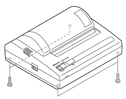
How to disassembly the DPU-414 Serial Thermal Printer is given in this chapter.
Procedure:
1.Remove the 4 screws in the bottom of the printer.
2.Lift the upper cover straight up to remove.
Figure 2-1 Remaining the Screws of the Upper Cover
2-1
2-2

CHAPTER 3
ADJUSTMENT
How to adjust the applied energy for the thermal head and the charging time for the battery are given in this chapter.
3.1ADJUSTING THE APPLIED ENERGY FOR THE THERMAL HEAD
Procedure:
1.Check the head rank mark (A, B or C) displayed on the FPC of the printer mechanism
Figure 3-1 Head Rank Mark
3-1
2.Initialize the dipswitches with the following procedure:
1.Remove the AC adapter from the power plug.
2.Connect the AC adapter to the power plug.
3.Power ON the printer while pressing the ONLINE and PAPER FEED buttons on the printer.
4.Release the ONLINE and PAPER FEED buttons after the ONLINE and OFFLINE Iamps blink. It takes approx. 30 seconds.
3.Initialize the applied energy for the thermal head with the following procedure:
1.Prepare a parallel interface communication between the printer and the computer.
2.Send the following command from the computer: ESC + "!" + FF16 + FF16
4.Set the head rank and the dipswitches with the following procedure:
1.Prepare a parallel interface communication between the printer and the computer.
2.2. Send one of the following commands from the computer according to the head rank used:
Head rank |
Command |
A |
ESC + "." + EB16 + FF16+ FF16+ 7316 |
B |
ESC + "." + EB16 + FF16+ FF16+ 7216 |
C |
ESC + ". " + EB16 + FF16+ FF16+ 7116 |
5.Make sure that the printing density is OK by printing a test print.
3-2
Loading...