


BUSINESS PRINTER
OWNER'S MANUAL

Warning
“This equipment has been tested and found to comply with the limits for a Class B digital device, pursuant to Part 15 of the FCC Rules. These limits are designed to provide reasonable protection against harmful interference in a residential installation. This equipment generates, uses, and can radiate radio frequency energy and, if not installed and used in strict accordance with the instructions, may cause harmful interference to radio communications. However there is no guarantee that interference will not occur in a particular installation. If this equipment does cause harmful interference to radio or television reception, which can be determined by turning the equipment off and on, the user is encouraged to try to correct the interference by one or more of the following measures:
—Reorient the receiving antenna
—Increase the separation between the equipment and receiver.
—Connect the equipment into an outlet on a circuit different from that to which the receiver is connected.
—Consult the dealer or an experienced radio/TV technician for help.
“It is necessary to use shielded interconnect cables to insure compliance with FCC Class B limits for radio frequency emissions."
Caution: Changes or modifications not expressly approved by the party responsible for compliance could void the user’s authority to operate the equipment.
This manual and the program samples described in it are copyrighted by SEIKO Precision Inc. with all rights reserved. No part of this publication may be reproduced, stored in a r e t r i e v a l s y s t e m , o r t r a n s m i t t e d , i n a n y f o r m o r b y a n y m e a n s , m e c h a n i c a l , photocopying, recording or otherwise, without the prior written permission of SEIKO Precision Inc.
*HP is a registered trademark of HEWLETT-PACKARD Company.
*PCL is a registered trademark of HEWLETT-PACKARD Company.
*DeskJet 500/RuggedWriter 480 are a registered trademark of HEWLETT-PACKARD Company.
*Epson is a registered trademark of S.Epson Corporation.
*LQ-2550 is a registered trademark of S.Epson Corporation.
*IBM is a registered trademark of International Business Machines Corporation.
*IBM2931 is a registered trademark of International Business Machines Corporation.
*Windows is a registered trademark of Microsoft Corporation.
Copyright © 1999 by SEIKO Precision Inc.
Chiba, Japan
OWNER'S MANUAL
 24-pin
 wide-carriage


 dot matrix printer
As an ENERGY STAR Partner, SEIKO Precision Inc. has determined that this product meets the ENERGY STAR guidelines for energy efficiency.
- Outline of the International ENERGY STAR Office Equipment Program -
The International ENERGY STAR Office Equipment Program is an international program that promotes energy saving through the use of computers and other office equipment. The program backs the development and dissemination of products with functions that effectively reduce energy consumption. It is an open system in which business proprietors can participate voluntarily. The targeted products are office equipment such as computers, displays, printers, facsimiles, and copiers. Their standards and logos uniform among participating nations.
C 1999 SEIKO Precision Inc.
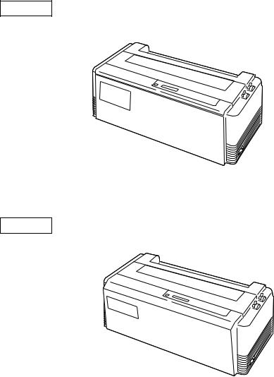
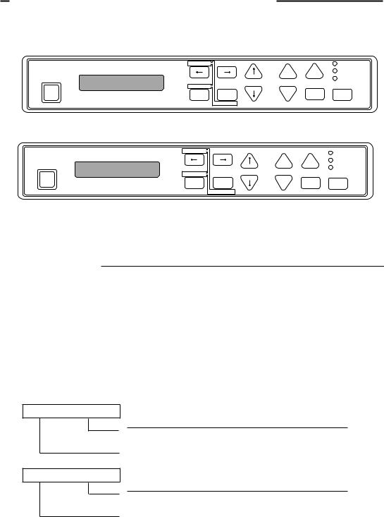
This manual is for the following two models of the printer.
Although these two models, model A and model B, look different,
the difference is only the appearance of the casing areas at the front. The functions of these models are very much the same.
Refer to the manual of the model A, for the manual of the model B.
Model A
Model B

Contents
U n p a c k i n g t h e p r i n t e r. . . . . . . . . . . . . . |
1 |
Q u i c k s t a rt u p.............................. |
2 |
1. Introduction
Features. . . . . . . . . . . . . . . . . . . . . . . . . . . . . . . . . . . . .. |
3 |
Options and expendables. . . . . . . . . .. .. . . .. |
4 |
Printer description. . . . . . . . . . . . . . . . . . . .. . .. . |
6 |
2. Setting up
|
Installing the paper rack . . . . . . . . . . .. . . . . |
1 0 |
|
|
Installing the sound seal cover . . ...... |
1 0 |
|
|
Installing the ribbon cassette . . . . . . . . |
11 |
|
|
Connecting the computer . . . . . . . . . .. . . . . |
1 2 |
|
|
Connecting the power cord . . . . . . . . . . . . . |
1 2 |
|
|
Loading the paper . . . . . . . . . . .. . . . . . . . .. . . . . . |
1 3 |
|
|
Adjusting print head position . . . .. . . . . |
1 5 |
|
3. |
Control panel and operations |
|
|
|
Control panel and indicators . . . . . . . . . |
1 6 |
|
|
Paper parking . . . . . . . . . . . . . . . . . . . . . . . .. . . . . . |
2 0 |
|
|
Printing test pattern . . . . . . . . . . . . .. . . . . . . . . |
2 1 |
|
|
Demonstration print-out . . . . . . . .. . . . . . . . |
2 2 |
|
|
Tearing off a form . . . . . . . . . . . .. . . . . . .. . . . . . . |
2 2 |
|
|
Power-on operation summary . . .. . . . . . |
2 3 |
|
4. |
Basic setup options |
|
|
|
About basic setup options . . . . . . . . . . . . . |
2 4 |
|
|
Printing multipart paper . . . . . .... . . . . . . . |
2 6 |
|
|
Selecting page length |
|
|
|
|
for fanfold paper. . . . . . . . . . . . . . . . . . . . . . |
2 6 |
|
Selecting single sheet |
|
|
|
|
paper size . . . . . . . . . . . . . . . . . .. . . . . . . . . . . . |
2 7 |
|
Selecting font style . . . . . . . . . . . . . . . . . . . . . . |
2 8 |
|
|
Selecting character spacing . . . . . . . . . . . |
2 9 |
|
|
Enlarging/compressing print . . . . . . . . . |
3 0 |
|
|
Setting top of form position . . . . ... . . . . |
3 1 |
|
|
Loading user setup options . . . . . . . . . . . . |
3 1 |
|
5. |
Extended setup options |
|
|
|
About extended setup options . . . ... . . |
3 3 |
|
|
|
P r i n t e n h a n c e m e n t |
|
|
1 0 |
Emulation................................... |
3 6 |
|
11 |
Character table (HP mode)............... |
3 6 |
|
1 2 |
Character table (Epson mode)........... |
3 7 |
|
1 3 |
Character table (IBM mode)............. |
3 7 |
|
1 4 |
National font style........................ |
3 8 |
|
1 5 |
Code page................................... |
3 8 |
|
1 6 |
IBM Alternate graphic mode............ |
3 9 |
|
1 7 |
Carriage return (CR)....................... |
3 9 |
|
1 8 |
Line feed (LF)............................... |
3 9 |
|
1 9 |
Line feed spacing.......................... |
4 0 |
|
2 0 |
Slashed zero................................ |
4 0 |
|
2 1 |
Set default tab stops...................... |
4 0 |
|
2 2 |
Lock-in the page length................. |
4 0 |
|
2 3 |
Print quality ............................... |
4 1 |
|
2 4 |
Lock-in the font........................... |
4 1 |
|
2 5 |
Lock-in the character |
|
|
|
spacing .................................... |
4 1 |
|
2 6 |
Lock-in the print quality................. |
4 1 |
|
B a r c o d e p r i n t e n h a n c e m e n t |
|
2 7 |
Enable barcode print .................... |
4 2 |
2 8 |
Barcode type............................... |
4 2 |
2 9 |
Bar code size................................ |
4 4 |
3 0 |
Enlarged character size................... |
4 4 |
3 1 |
Graphic Print Speed ...................... |
4 5 |
3 2 |
Accent character........................... |
4 5 |
3 3 |
Setting of the FF code at TOF ......... |
4 5 |
|
H P m o d e e n h a n c e m e n t |
|
3 8 |
PCL mode .................................. |
4 6 |
3 9 |
Secondary character table ............ |
4 6 |
|
P a p e r h a n d l i n g e n h a n c e m e n t |
|
4 0 |
Set the top margin........................ |
4 7 |
4 1 |
Set the bottom margin .................. |
4 7 |
4 2 |
Set the left margin........................ |
4 7 |
4 3 |
Set the right margin ..................... |
4 8 |
4 4 |
Fanfold paper width ..................... |
4 8 |
4 5 |
Autoscroll delay........................... |
4 8 |
4 6 |
Override bottom margin ............... |
4 9 |
4 7 |
Label mode................................. |
4 9 |
4 8 |
Paper out detection ....................... |
5 0 |
4 9 |
Cut sheet feeder type ..................... |
5 0 |
5 0 |
Setting of the auto |
|
|
scrolling position ................ |
5 0 |
5 1 |
Line Feed Speed............................ |
5 1 |
|
C o m m u n i c a t i o n e n h a n c e m e n t |
|
6 0 |
Interface type............................... |
5 1 |
6 1 |
SELECT IN signal......................... |
5 1 |
6 2 |
Parity bits.................................. |
5 1 |
6 3 |
Data length................................. |
5 2 |
6 4 |
Stop bit..................................... |
5 2 |
6 5 |
Communication protocol ............. |
5 2 |
6 6 |
Communication speed .................. |
5 2 |
6 7 |
Serial error check ........................ |
5 3 |
6 8 |
CTS signal ................................. |
5 3 |
6 9 |
CD signal .................................. |
5 3 |
7 0 |
DSR signal................................. |
5 3 |
7 1 |
Communication buffer size ........ |
5 4 |
7 2 |
Busy/ACK timing......................... |
5 4 |
7 3 |
Data latch timing.......................... |
5 4 |
7 4 |
Setting of whether ERROR/PE |
|
|
signals are output or not . . . . . . |
5 4 |
|
M i s c e l l a n e o u s |
|
8 0 |
Print direction............................. |
5 5 |
8 1 |
LCD display language.................... |
5 5 |
8 2 |
Invert LCD display ...................... |
5 5 |
8 3 |
Software controlled setup ............. |
5 6 |
8 4 |
Lock the RESET key...................... |
5 6 |
8 5 |
Setting of ENERGY STAR ............. |
5 6 |
8 6 |
Saving user setup options ............. |
5 6 |
8 7 |
Printing list of option settings . . . . . |
5 6 |
6. Setting the application software
About printer driver . . . . . . . . . . . . . . . . . . . . . . |
5 7 |
Printer driver selection . . . . . . . . . . . . . . . . . . |
5 7 |
Connecting the BP-9000 printer |
|
in the HP Environment . . . . . . . . . . . . . |
5 8 |
Saving Your Setup .................... |
5 9 |
7. Troubleshooting
Error messages . . . . . . . . . . . . . . . . . . . . . . |
. . . . . . 6 0 |
Troubleshooting guide . . . . . . . . . . . . . |
. . . . . 6 1 |
Input hexadecimal dump mode |
. . . . . 6 2 |
8. Maintenance
Cleaning. . . . . . . . . . . . . . . . . . . . . . . . . . . . . . . . . . . . . . |
6 3 |
Lubrication. . . . . . . . . . . . . . . . . . . . . . . . . . . . . . . . . . |
6 3 |
Printer cover removal . . . . . . . . . . . . . . . . . . . |
6 4 |
Vertical alignment mode . . . . . . . . . . . . . . . |
6 6 |
9. Bar code and enlarged character function
Bar code function |
|
Outline of bar code function......... . . . .. . . . |
6 9 |
Makeup of bar code................... . ........ |
6 9 |
Bar code command list........................ |
7 0 |
(1) Bar code type........................ |
7 0 |
(2) Element width....................... |
7 1 |
(3) Bar code height..................... |
7 1 |
(4) Setting HRI on and off............. |
7 1 |
(5) HRI font.............................. |
7 2 |
(6) Check character..................... |
7 2 |
(7) Starting the bar code data sequence. . . |
7 2 |
(8) Ending the bar code data sequence. . . . |
7 3 |
(9) Bar code data sequence............. |
7 3 |
(10) Printing density................... |
7 3 |
(11) Guide bar expansion.............. |
7 3 |
(12) Start and stop characters......... |
7 4 |
(13) Barcode rotational angle......... |
7 4 |
(14) Disabling HRI of the start |
|
and stop characters.......... |
7 4 |
(15) Value input mode.................. |
7 4 |
(16) Initializing the bar code mode. . . . |
7 5 |
Data processing in the bar |
|
code data sequence........... |
7 5 |
Printing bar codes.................... |
7 6 |
HRI...................................... |
7 6 |
Error processing...................... |
7 7 |
Code 128 subset transition rule. . . . . . |
7 7 |
UPC-E conversion rule.............. |
7 8 |
Calculating the check character. . . . . . |
7 8 |
Other.................................... |
8 0 |
Element printing................... |
8 0 |
Enlarged |
|
character function |
|
Outline of enlarged |
|
characterfunction............ |
8 2 |
Enlarged character |
|
command list................. |
8 2 |
(1) Executing backspacing............ |
8 3 |
(2) Executing line feeding............. |
8 3 |
(3) Executing form feeding............ |
8 4 |
(4) Executing carriage return.......... |
8 4 |
(5) Initializing the enlarged |
|
character mode............... |
8 4 |
(6) Arrangement of enlarged |
|
characters..................... |
8 5 |
(7) Cell magnification for |
|
enlarged characters.................. |
8 5 |
(8) All-character set for |
|
enlarged characters................... |
8 6 |
(9) Selecting an enlarged |
|
character font......................... |
8 6 |
(10) Height expansion for |
|
enlarged characters.................. |
8 7 |
(11) HMI for enlarged characters.......... |
8 7 |
(12) VMI for enlarged characters........... |
8 8 |
(13) Setting and canceling the |
|
enlarged character mode. . . . . . |
8 8 |
(14) Enlarged character cell offset. . . . . |
8 9 |
(15) Enlarged character pitch......... |
8 9 |
(16) Enlarged character quality....... |
9 0 |
(17)Enlarged character rotational angle.. 9 0
(18)Setting and canceling enlarged
|
character smoothing. . |
9 1 |
(19) |
Enlarged character top offset. . . . . . |
9 1 |
(20) |
Setting and canceling underlining |
|
|
of enlarged characters. . . |
9 2 |
(21) Enlarged character |
|
|
|
widthwise expansition....... |
9 2 |
(22) Horizontal printing position |
|
|
|
for enlarged characters... |
9 3 |
(23) |
Vertical printing position for |
|
|
enlarged characters. . |
9 3 |
Enlarged character print samples. . . . . |
9 4 |
|

Appendices |
|
A. Specifications |
|
Printing specifications . . . . . . . . . . . . . |
9 5 |
Parallel interface |
|
specifications . . . . . . . . . . . . . .. . |
1 0 0 |
Serial interface |
|
specifications . . . . . . . . . . . . . .. . |
1 0 1 |
Other specifications . . . . . .... . . . . . . . |
1 0 2 |
B. Control code summary
IBM mode . . . . . . . . . . . . . . . . . . . . . . . . . . . .. . 1 0 3 Epson mode . . . . . . . . . . . . . . . . . . . . . . . .. . . 1 0 9 PCL mode . . . . . . . . . . . . . . . . . . . . . . . . . .. . . . 11 5 Setup options control codes . . . . . . . . 1 2 2
C.
D.
Character sets. . . . . . . . . . . . .. .. . . . .. . .. . . 1 2 7
Reverse control panel . . . . . . . . . . . |
1 3 6 |
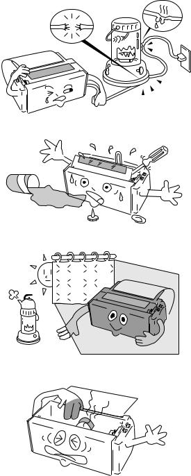
Caution for use
Power sourc e
•Be sure to insert the power plug only in a wall unit of the voltage designated in the voltage selector switch and on the rating plate on the back of the unit.
•Do not place the power cord near heat sources or place heavy objects on it. Do not bend or twist the power cord.
Foreign matter and water
•Keep your hands and personal items, such as scarfs and ties, away from the carriage mechanism while the printer is operating. The carriage moves with considerable force.
•Keep the printer dry. If you accidentally spill water on the machine, turn the power off immediately and wipe it dry. Do not turn t h e p o w e r o n u n t i l t h e m a c h i n e i s completely dry.
Installation environment
•The printer should be used where humidity is low, where there is little dust, and where the printer is not in direct sunlight.
•Avoid placing or leaning anything on top of the printer. If you accidentally drop any object into the machine, turn the power off immediately, then carefully remove the object.
•Do not twist the ribbon while installing it.
Operating condition
•Wait at least two seconds after turning power o ff b e f o r e t u r n i n g i t b a c k a g a i n . T h e initialization process may not be performed correctly if this is not done.
•Do not touch the print head immediately after printing because it is too hot.
•Never operate the printer without paper or paper properly installed.
If you use paper that is not as wide as the platen, be sure that printing does not exceed paper width. Use software control to change the width of the print line.
•Never insert or pull out an interface cable while the power to the printer and computer is on.
•Be sure to turn off the printer before turning off a connected host computer.
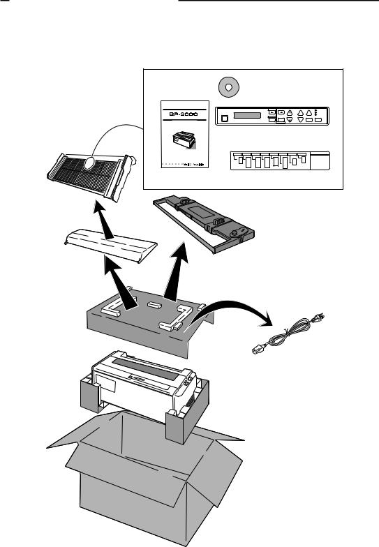
Unpacking the printer
Unpacking the printer
Check the cartons for the following items:
Paper Rack
(See page 10)
|
|
CD-ROM |
|
|
|
|
|
|
|
|
(Driver-CD with Owner's |
|
|
||||
|
|
Manual, printer driver software) |
||||||
BUSINESS PRINTER |
|
|
TOFSET |
LF.M |
LF |
FF |
|
|
|
|
|
POWER |
|
||||
|
|
|
|
|
|
|
LINE |
ON |
|
RESET |
L C D |
PARK |
QUALITY |
|
|
OUT.P |
|
|
|
|
BIN |
RLF.M |
RLF |
ONLINETEAROFF |
|
|
OWNER'SHandbookMANUAL |
|
|
EXIT |
ENTER |
|
|
|
|
|
|
SETUP |
ALT |
|
|
|
|
|
|
|
Reverse Control Panel |
||||||
|
|
(See page 55, 135) |
|
|||||
Handbook |
|
Operation Guide Sheet |
||||||
|
|
|
(See page 7) |
|
|
|||
Sound Seal Cover |
Ribbon Cassette |
(See page 10) |
(#SBP-1051) |
|
(See page 11) |
Printer |
Power Cord |
(See page 12)
1
Quick startup
Quick startup
To make your first print, follow the procedure below . For more detailed instructions on setting your printer, please refer to the page indicated.
To set up the printer
1. Install the paper rack, the sound seal cover, and the ribbon cassette — Pages 10 and 11.
2. Load the single cut sheet paper or fanfold paper. Press the FF key to load the paper — Pages 13 and 14.
Self |
Test |
|
|
||
Self |
Test |
|
|
|
|
To make a test print
1.Set the paper size of the printer in the setup options — Pages 26 and 27.
2.Press the LF key and hold while initializing the printer by the RESET key. Hold the LF key until the self test starts — Page 21.
? ?
?
?
?
?
To connect your computer
1.With all equipment turned off, connect the printer to your computer. Interface cable is purchased separately — Page 12.
2.Use the extended setup options (emulation t y p e a n d c o m m u n i c a t i o n e n h a n c e m e n t section) to match the specification needs between the printer and your computer — Pages 33 to 56.
3.S e l e c t t h e p r i n t e r d r i v e r f r o m y o u r application software — Page 57.
2
|
|
|
1. Introduction |
|
|
1. Introduction |
|
Features |
|
||
|
|
Barcode Print available |
|
|
• 13 resident barcode type |
Industrial 2/5, Interleave 2/5, Codabar, Matrix 2/5, Code 11, Code 39, |
|
|
|
|
Code 93, Code 128, EAN-8, EAN-13, UPC-A, UPC-E, Postnet |
|
|
Enlarged character printing |
|
|
|
|
Characters can be enlarged (by up to 127 times as large x 127 times as |
|
|
|
large) using the enlarged character command unique to this printer. |
|
|
|
Software commands are used for control. |
Contain the 3 kind of emulations
Compatible to major printer emulations, Hewlett Packard, IBM and Epson printers.
• |
Hewlett Packard |
Rugged Writer 480 (PCL3) compatible |
• |
EPSON |
LQ-2550 compatible |
• |
IBM |
2391 compatible |
Wide selection of paper size
• Single cut sheet papers |
A3, A4, B4, B5, Letter, Legal |
|
• |
Fanfold continuous paper |
5 - 15 inch wide and 2 - 16.5 inch long paper |
• |
Multi-part paper |
Original plus 8 copies |
|
|
(total clearance: 0.635mm (0.025”) |
• |
Labeling paper |
Label peel-proof capability |
Full option of font types and variation of character spacings
• |
10 resident fonts |
Courier, Prestige, Script, OCR-A, OCR-B, Gothic, Orator, Orator-S, |
|
|
Roman, and Sans Serif |
• |
8 character spacings |
10, 12, 15, 16.7, 17.1, 20, 24 characters per inch (CPI), and |
|
|
proportional and 1/2 proportional characters |
Enlarge/reduce your layout to fit in any paper size
•you can print the same layout of the document in different paper size.
Easy operation
•Multiple display language for international use.
•Upside down display enables operation from the back of the printer.
Superb compatibility and connectability
•Communication protocols adjustable to any computer.
•Interface connections provided for parallel, RS-232C.
•Parallel and serial interface are switchted automatically when "AUTO" setting is selected.
3
1. Introduction
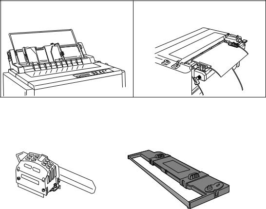
Options and expendables
The Cut Sheet Feeder greatly enhances the speed and |
The Pull Tractor is recommended for applications using |
efficiency of document printing by feeding of up to 80 single |
extra thick forms. |
sheets of paper without reloading. |
|
Paper dimensions |
|
Length: 14.5"~7.0" |
|
Width : 15.0"~5.7" |
|
Weight : 15~21 lbs. |
|
Cut Sheet Feeder |
Pull Tractor (#BP-57008) |
|
1 Bin |
(#BP-78009) |
|
2 Bin |
(#BP-78009E) |
|
|
|
|
|
|
|
Matrix Print Head |
Ribbon Cassette (#SBP-1051) |
4
1. Introduction
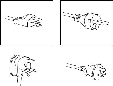
Power cord
One of the following plug types is supplied. See "Connecting the power cord" on page 12.
Please see the rating plate on the back of your printer for appropriate input voltage and consult your dealer for a specific type of power cord, if necessary.
120V For USA
220-240V For Asia and Europe |
240V For U.K. |
|
240V For Australia |
|
|
|
5

1. Introduction
Printer description
Ribbon Cassette |
Paper Guide |
|
|
|
Platen |
Paper Bail
Paper Select Lever
(Friction Lever)
 Head Adjustment Lever
Print head
Power Switch
Sound Seal Cover
Printer Cover
Paper Cutter
Paper Rack
Top Rear Cover 
Operator Panel |
Tractor Lock Lever |
Rear Cover
Tractor Cover
6
1. Introduction
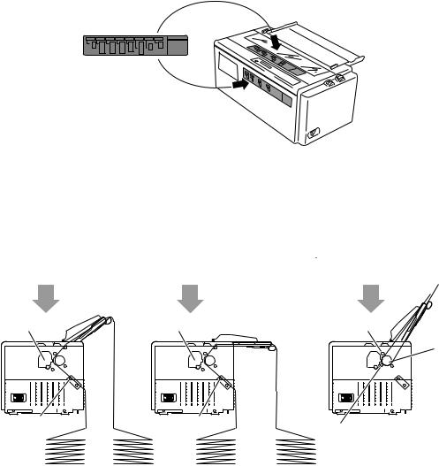
Operation guide sheet
The operation guide sheet helps you to operate some of the basic options on the front control panel. You can peel the adhesive backed paper and stick it anywhere on your printer for convenience.
Precaution for extra-thick paper usage
Extra-thick continuous paper, especially 9-part multi-layer paper may get jammed in the printer due to its stiffness and inflexibility. When using such paper, set the paper rack in the slant position shown in the figure.
|
Push Tractor Method |
|
Friction Feed Method |
|
• Multiple Fanfold Paper |
• Single ply Fanfold Paper |
• Single Sheet Paper |
||
• Label Fanfold Paper |
|
|
|
|
Print Head |
Print Head |
Print Head |
|
|
Platen |
|
|
|
|
|
|
|
|
|
|
|
|
|
|
|
|
|
|
|
|
|
|
|
|
|
|
|
|
|
|
|
|
|
|
|
|
|
|
|
|
|
|
|
|
|
|
|
|
|
|
|
|
|
|
|
|
|
|
|
|
|
|
|
|
|
|
|
|
|
|
|
|
|
|
|
|
|
|
|
|
|
|
|
|
|
|
|
|
|
|
|
|
|
|
|
|
|
|
|
|
|
|
|
|
|
|
|
|
|
|
|
|
|
|
|
|
|
|
|
|
|
|
|
|
|
|
|
|
|
|
|
|
|
|
|
|
|
|
|
|
|
|
|
|
|
|
|
|
|
|
|
|
|
|
|
|
|
|
|
|
|
|
|
|
|
|
|
|
|
|
|
|
|
|
|
|
|
|
|
|
|
|
|
|
|
|
|
|
|
|
|
|
|
|
|
|
|
|
|
|
|
|
|
|
|
|
|
|
|
|
|
|
|
|
|
|
|
|
|
|
|
|
|
|
|
|
|
|
|
|
|
|
|
|
|
|
|
|
|
|
|
|
|
|
|
|
|
|
|
|
|
|
|
|
|
|
|
|
|
|
|
|
|
|
|
|
|
|
|
|
|
|
|
|
|
|
|
|
|
|
|
|
|
|
|
|
|
|
|
|
|
|
|
|
|
|
|
|
|
|
|
|
|
|
|
|
|
|
|
|
|
|
|
|
|
|
|
|
|
|
|
|
|
|
|
|
|
|
|
|
|
|
|
|
|
|
|
|
|
|
|
|
|
|
|
|
|
|
|
|
|
|
|
|
|
|
|
|
|
|
|
|
|
|
|
|
|
|
|
|
|
|
|
|
|
|
|
|
|
|
|
|
|
|
|
|
|
|
|
|
|
|
|
|
|
|
|
|
|
|
|
|
|
|
|
|
|
|
|
|
|
|
|
|
|
|
|
|
|
|
|
|
|
|
|
|
|
|
|
|
|
|
|
|
|
|
|
|
|
|
|
|
|
|
|
|
|
|
|
|
|
|
|
|
|
|
|
|
|
|
|
|
|
|
|
|
|
|
|
|
|
|
|
|
|
|
|
|
|
|
|
|
|
|
|
|
|
|
|
|
|
|
|
|
|
|
|
|
|
|
|
|
|
|
|
|
|
|
|
|
|
|
|
|
|
|
|
|
|
|
|
|
|
|
|
|
|
|
|
|
|
|
|
|
|
|
|
|
|
|
|
|
|
|
|
|
|
|
|
|
|
|
|
|
|
|
|
|
|
|
|
|
|
|
|
|
|
|
|
|
|
|
|
|
|
|
|
|
|
|
|
|
|
|
|
|
|
|
|
|
|
|
|
|
|
|
|
|
|
|
|
|
|
|
|
|
|
|
|
|
|
|
|
|
|
|
|
|
|
|
|
|
|
|
|
|
|
|
Tractor |
|
|
|
|
|
|
|
Tractor |
|
Friction Roller |
|||||||||||||||||||||||||||||||||||||
|
|
|
|
|
|
|
|
|
|
|
|
|
|
|
|
|
|
|
|
|
|
|
|
|
|
|
|
|
|
|
|
|
|
|
|
|
|
||||||||||||||
|
|
Fanfold Paper |
|
|
|
|
|
|
|
|
|
|
|
|
|
|
|
|
|
|
|
|
|
|
|
|
|
|
|
|
|
|
|
|
|
|
|
||||||||||||||
|
|
|
|
|
|
|
|
|
Description |
Single-ply |
|
|
|
Multiple Copies |
Label Paper |
|
|
|
|
|
|
|
|
|
|
|
|
|
|
||||||||||||||||||||||
|
|
|
|
|
|
|
|
|
Paper width |
|
|
|
|
|
|
|
|
|
|
|
|
5~15 inch |
|
|
|
|
|
|
|
|
|
|
|
|
|
|
|
||||||||||||||
|
|
|
|
|
|
|
|
|
Paper length |
|
|
|
|
|
|
|
|
|
|
|
2~16.5 inch |
|
|
|
|
|
|
|
|
|
|
|
|
|
|
|
|||||||||||||||
|
|
|
|
|
|
|
|
|
|
|
Ply |
single |
|
|
Original+8 max. |
single |
|
|
|
|
|
|
|
|
|
|
|
|
|
|
|||||||||||||||||||||
|
|
|
|
|
|
|
|
Total thickness |
0.065~0.12mm |
|
|
|
0.635mm max. |
0.18mm max. |
|
|
|
|
|
|
|
|
|
|
|
|
|
|
|||||||||||||||||||||||
|
|
|
|
|
|
|
|
|
Paper weight |
14lbs.~28lbs. |
|
|
|
|
non-carbon |
125Kg max. |
|
|
|
|
|
|
|
|
|
|
|
|
|
|
|||||||||||||||||||||
|
|
|
|
|
|
|
|
|
|
|
|
|
|
|
|
|
53g/m2 ~105g/m2 |
|
|
|
|
|
|
|
|
|
|
|
|
|
|
|
|
|
|
||||||||||||||||
|
|
|
|
|
|
|
|
|
|
|
|
|
|
|
|
|
|
|
|
|
|
|
|
|
|
|
|
|
|
|
|
|
|
|
|
|
|
|
|||||||||||||
|
|
Single Sheet Paper |
|
|
|
|
|
|
|
|
|
|
|
|
|
|
|
|
|
|
|
|
|
|
|
|
|
|
|
|
|
|
|
|
|
|
|
||||||||||||||
|
|
|
|
|
|
|
|
|
Description |
|
Single-ply |
|
|
|
|
|
|
|
|
|
|
|
|
|
|
|
|
||||||||||||||||||||||||
|
|
|
|
|
|
|
|
|
|
Paper size |
A3, A4, B4, B5 Letter, Legal |
|
|
|
|
|
|
|
|
|
|
|
|
|
|
|
|
||||||||||||||||||||||||
|
|
|
|
|
|
|
|
|
|
|
Ply |
|
|
|
|
single |
|
|
|
|
|
|
|
|
|
|
|
|
|
|
|
|
|||||||||||||||||||
|
|
|
|
|
|
|
|
Total thickness |
0.08~0.12mm |
|
|
|
|
|
|
|
|
|
|
|
|
|
|
|
|
||||||||||||||||||||||||||
|
|
|
|
|
|
|
|
|
Paper weight |
17lbs.~28lbs. |
|
|
|
|
|
|
|
|
|
|
|
|
|
|
|
|
|||||||||||||||||||||||||
|
|
|
|
|
|
|
|
|
|
|
|
|
|
|
|
|
64g/m2~105g/m2 |
|
|
|
|
|
|
|
|
|
|
|
|
|
|
|
|
||||||||||||||||||
7
1. Introduction
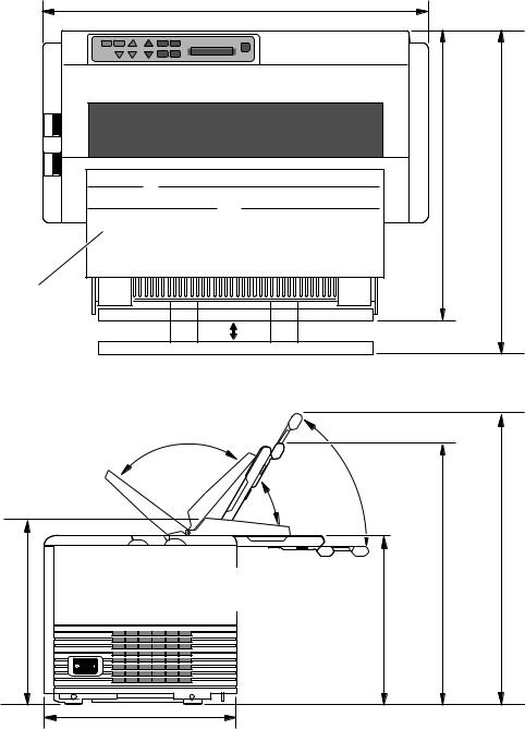
Physical dimension(Model A)
24 .4" (620mm) |
17.9"
(455mm)
19.9"
(505mm)
Paper Rack in flat position (Continuous paper setting)
Sound Seal Cover |
Paper Rack in upright position (Single sheet setting)
|
|
|
17.1" |
|
Paper Rack in flat position |
15.4" |
(435mm) |
|
|
||
|
(390mm) |
|
|
|
(Continuous paper setting) |
|
|
|
|
|
|
11.6" |
|
10.2" |
|
(295mm) |
|
(260mm) |
|
12.0" |
(305mm) |
Weight: 44.1 lbs. (20 kg)
8
1. Introduction
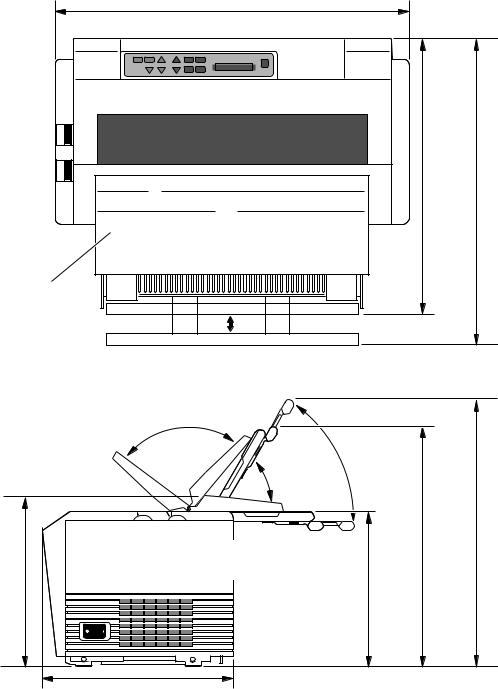
Physical dimension(Model B)
24.4" (620mm) |
18.9"
(480mm)
20.9"
(530mm)
Paper Rack in flat position (Continuous paper setting)
Sound Seal Cover |
Paper Rack in upright position (Single sheet setting)
|
|
|
17.1" |
|
Paper Rack in flat position |
15.4" |
(435mm) |
|
|
||
|
(390mm) |
|
|
|
(Continuous paper setting) |
|
|
|
|
|
|
11.6" |
|
10 .2" |
|
(295mm) |
|
(260mm) |
|
13.0"(330mm) |
Weight: 44.1 lbs. (20 kg)
9
2. Setting up
2. Setting up
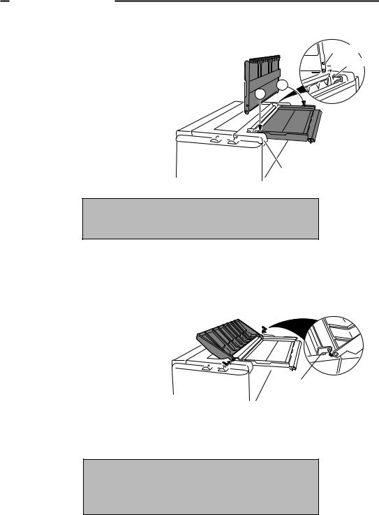
Installing the paper rack
1.S l i d e b o t h p a p e r g u i d e s t o t h e extreme left and right edges of the paper rack.
2.With the two small pivots on either side of the paper rack downward, fit the pivots in the groove on the rear top cover.
3.P l a c e t h e p a p e r r a c k i n u p r i g h t position for single cut sheet paper a n d l a y i t d o w n f o r f a n f o l d continuous paper.
Pivots
Groove
2
1
Rear Top Cover
Note
The paper guides should be placed to the outside edges during the installation or removal of the paper rack.
Installing the sound seal cover
1. Lay the sound seal cover upside down on the printer.
2. Fit one of the holes of the cover to the stud of the L-angle hinge on one side of the printer.
3. Fit the other hole to the other stud
b y p r e s s i n g t h e L - a n g l e h i n g e |
L-angle Hinge |
|
|
inward then out through the hole. |
|
Note
Make sure that both studs are out through the hole completely, otherwise, the sound seal cover will be stuck in place.
10
2. Setting up
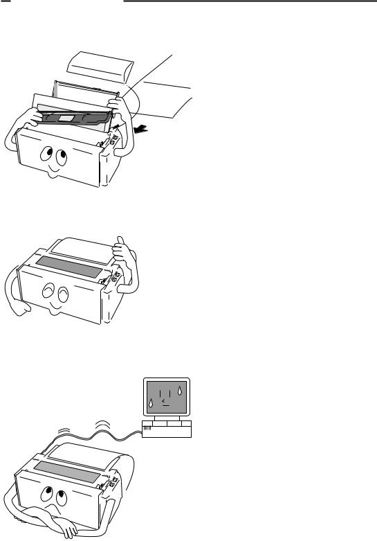
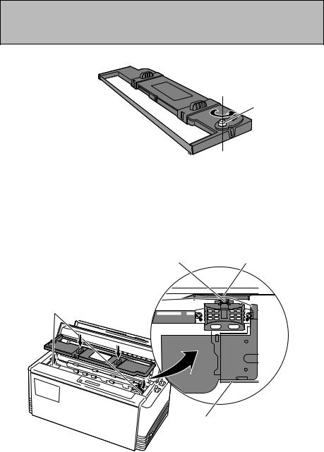
Installing the ribbon cassette
Turn OFF the printer's power and remove the used ribbon cassette, if necessary, by pulling straight upward.
1.Open the printer cover.
2.Manually move the print head to the extreme right side of the printer for easy installation of the ribbon. Do not try to move the print head if the power is on.
CAUTION
Do not touch the print head if the printer has been running for a long time. Wait until the print head is cooled off.
3.Turn the ribbon feed knob in the direction of the arrow on the knob to remove any slack in the ribbon.
Remove any slack from ribbon
Ribbon Feed Knob
4.Place the ribbon cassette on the left and right cassette holders, such that the ribbon rests on the ribbon guide. Check to be sure that the ribbon drive shaft on the left cassette holder is inserted in the hole on the bottom of the ribbon cassette.
5.Turn the ribbon feed knob in the direction of the arrow on the knob to remove any slack in the ribbon.
6.Replace the front printer cover and set the head adjustment lever to the proper position for the best
print quality. |
Ribbon Guide |
Ribbon Mask |
|
Cassette Holders
Cassette Holder
11
2. Setting up
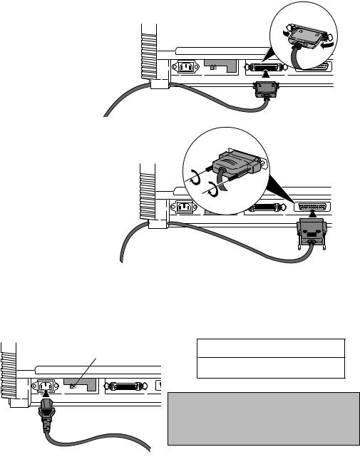
Connecting the computer
The printer has a parallel interface connector (Centronics) and a serial interface connector (RS232C). Before you connect an interface cable to your computer, you need to know what type of printer driver is supported by your software applications and what type of connector is needed to attach the printer to the computer.
Parallel Interface 36-pin plug
CAUTION |
|
220-240V |
120V |
Serial Interface 25-pin plug
13 |
1 |
25 |
14 |
Connecting the power cord
Check the power requirement printed on the rating plate on the rear of the printer before attaching the power cord and turning on the printer. Both POWER and P.OUT lamps light up when the printer is switched on correctly. The voltage selector should be set correctly as follows.
Voltage Selector
120V:USA, Canada
230V:Europe,Asia, Oceania
CAUTION |
|
|
|
13 |
|
220-240V |
120V |
|
|
25 |
1 |
Note
For continued protection against risk of fire and destruction of Power PCB Assembly, switch the voltage selector according to using voltage.
12
2. Setting up
Loading the paper
Fanfold continuous paper
1. |
Move the paper select lever |
toward the front of |
1 |
|
|
the fanfold paper setting. |
|
|
|
2. |
Set the print head adjustment lever |
. In general, |
2 |
|
|
used for one-part paper. (See page 15) |
|
|
|
3.Remove the rear cover  of the printer or open lock the cover in the open position.
4.Release the tractor lock levers  (upward), and
the marked position as shown in the figure, and lock it in place.
5. Open both tractor covers |
and place the fanfold paper so that |
the |
holes in the paper. Carefully close both tractor covers. |
|
|
Caution
Be careful not to catch your finger when closing the tractor covers.
6. |
After the paper is properly installed, re-adjust the left tractor to a |
(but |
|
not too taut) between the left and right tractors. |
|
7. |
To load the paper, press the PARK key or FF key on the front |
the |
|
top-of-form position 14/60 inch (6mm)below the top edge of the |
can |
|
be adjusted from 0/60 inch to 480/60 inches (8 inches = 203mm) |
page |
|
31. |
|
8. |
The paper bail automatically lowers to press the paper against the |
of |
|
the paper feeds more than one inch onto the platen. |
|
3 |
Rear Cover |
|
|
Not Too Taut !! |
|
5 |
Left Tractor Cover |
|
|
Left Margin Marker |
Right Tractor |
|
Releasing direction |
|
|
5 Tractor Cover |
|
|
4 |
Tractor Lock Lever |
13
2. Setting up
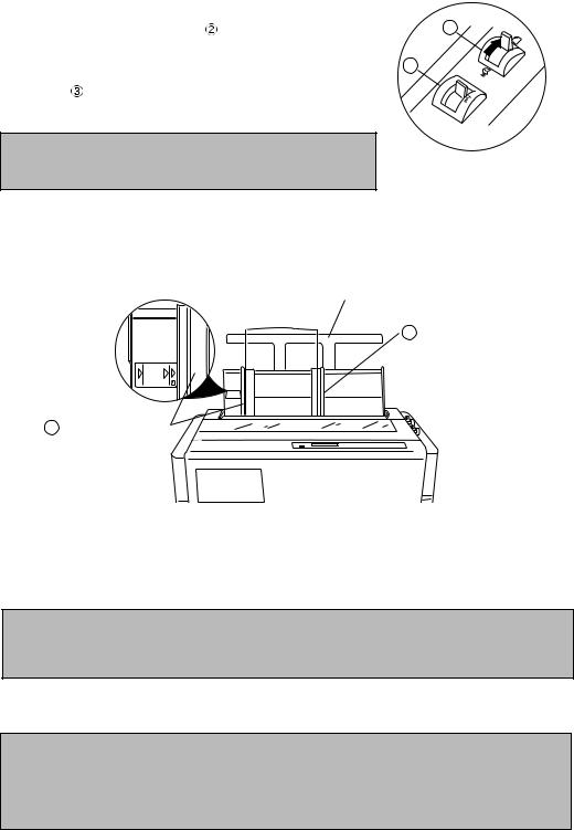
Single sheet paper
1.Move the paper select lever  toward the rear of the printer to the single
|
sheet setting. |
|
|
|
2. |
Set the print head adjustment lever |
. In general, position 1 is used |
1 |
|
|
for one-part paper. See page 15. |
|
|
|
3. |
Raise the paper rack to the vertical position and adjust the left |
2 |
||
|
||||
|
paper guide |
to the proper position for the size of the paper being |
|
|
|
used. |
|
|
|
Note
If the paper is not loaded on the proper mark, the printer may not detect the paper and will issue PAPER ERROR.
4.Place single sheet paper against the paper rack and let it slide behind the platen.
5.Adjust the right paper guide  so that it comfortably holds the paper in between the two paper guides.
Paper Size Marker |
Extension Arm |
4 Right Paper Guide
A3 B4
3Left Paper Guide
6.Press the PARK key or FF key to load the single sheet paper to the top-of-form position 14/60 inch (6mm) below the top edge of the paper. The top-of-form position can be adjusted from 0/60 inch to 480/60 inches (8 inches = 203mm) by using the front panel controls in the basic setup options on page 30.
Note
If the paper is not completely fed in, slightly push the paper downward. If it is still not fed in, look in the TROUBLESHOOTING section.
7.The paper bail automatically lowers to press the paper against the platen when the leading edge of the paper feeds more than one inch onto the platen.
Notes
1.Extension Arm
The extension arm is used to keep large size (Legal, B4) single sheets from falling behind the paper rack. When using the extension arm, pull the arm until it clicks and locks in place.
2.TEAR OFF keys are invalid with single sheet paper.
14
2. Setting up
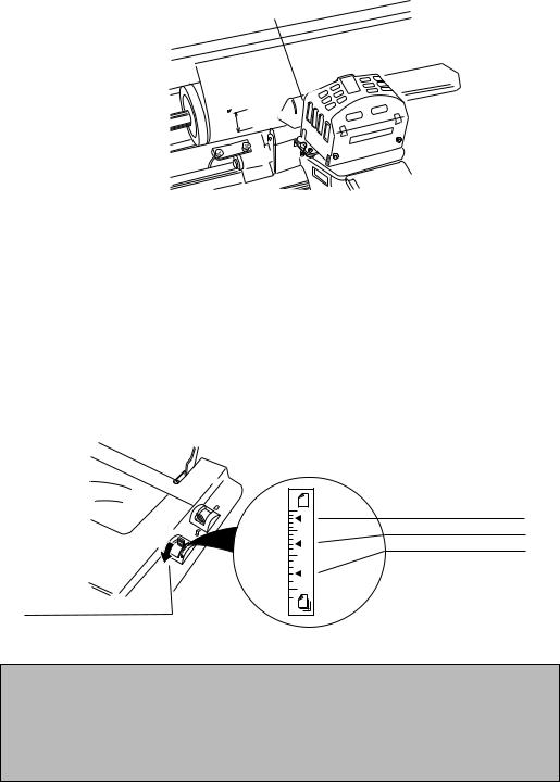
Paper alignment
Current print line location
The current printing line (DDD...) is the third line down from the top of the ribbon guide (line
spacing is 1/6 line: 6 LPI).
Ribbon Guide
0.5
A B C D
A
B
C
D
A
B
C
D
A |
A |
A |
A |
A |
|
||||
|
|
|||
|
|
|
||
B |
|
|
|
|
C |
|
|
|
|
D |
|
|
|
|
Adjusting the print head position
The head adjustment is used to obtain the best print quality possible for the specific paper being used. The print head position can be adjusted to accommodate printing on single and multipart forms. When using multipart forms, move the print head adjustment lever toward the front of the printer to widen the gap between the print head and the platen.
In general, position 1 is used for one-part paper. Moving the head adjustment lever one notch adjusts the print head gap an amount corresponding to the addition of one more paper part.
Re-adjustment of the lever may be required depending on the quality of the actual printout:
•If the ribbon smears on the paper, the gap is too narrow.
•If the printed image is too light to read, the gap is too wide.
1
5
9
Head Adjustment Lever: Move toward the front of the printer for thicker paper
1 |
1 part-paper: 2nd click |
|
5 part-paper: 8th click |
||
|
||
5 |
9 part-paper: 13th click |
|
|
(This scale is the suggested |
|
9 |
number of sheets |
|
|
for non-carbon part-paper.) |
Notes
1.The print head adjustment lever should be set before loading the paper to avoid paper jams.
2.If the printed image on the last copy of a multipart form is too light to read, set the MULTIPART mode in the basic setup options (see page 26). This will increase the striking intensity on multipart forms.
15
3. Control panel and operations
3. Control panel and operations
Control panel and indicators
Standard Panel
|
TOF SET |
|
|
|
|
POWER |
|
|
|
|
|
|
ON LINE |
L C D |
PARK |
QUALITY |
M.LF |
LF |
FF |
P.OUT |
|
||||||
|
BIN |
|
|
|
|
|
|
EXIT |
ENTER |
|
|
|
|
RESET |
SETUP |
ALT |
M.RLF |
RLF |
TEAR OFF ON LINE |
|
Alternate up-side down reverse panel
RESET |
L C D |
|
TOFSET |
LF.M |
LF |
FF |
POWER |
|
|
|
|
|
|
|
|
|
ONLINE |
PARK |
QUALITY |
|
|
OUT.P |
BIN |
RLF.M |
RLF |
ONLINETEAROFF |
|
|
|
|
|
|
EXIT |
ENTER |
|
|
|
SETUP |
ALT |
|
|
|
Note: The alternate reverse panel installation instruction is described in Appendix D.
Indicators
•Display window Liquid Crystal Display (LCD)
Displays status and errors during operation and menus in the setup options.
The followings are some examples of the display messages.
P.OUT FANFOLD |
|
|
Status message |
|
|
|
This indicates that the printer is in offline and paper out status. |
|
|||
|
|
|
Warning message |
COVER OPEN |
|
|
|
|
|
|
|
|
|
|
This indicates that the printer cover is open. Close the cover to |
|
|
|
|
|
|
|
resume the operation . |
If the printer is in the offline mode, the following appears on the display.
FANFOLD 11 15
15
Status message for fanfold continuous paper
This column indicates the page length; and the paper widlh.
This indicates the type of paper selected is fanfold continuous paper.
MANUAL: A4 P
Status message for single sheets paper
This indicates a paper size; B5 through A3 depending on the designated paper size (default A4) selected in the setup options. This indicates the type of paper selected is single sheet paper. MANUAL, BIN 1, BIN 2, BIN 1+2
16
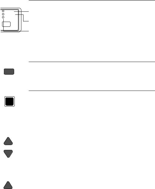
3. Control panel and operations
• Indicator lamps
Lamp |
On |
Off |
Blinking |
POWER
ON LINE
P.OUT
ON LINE
POWER |
Power On |
Power Off |
— |
(green) |
|
|
|
ON LINE |
Online |
Offline |
Cover open, or Head overheat |
(green) |
|
|
protection activating |
P.OUT |
Out-of-paper Paper-in |
Home sensor error, RAM error, |
(umber) |
|
or paper error. |
Function Keys
• ON LINE
ON LINE
• RESET
RESET
Pressing this key places the printer offline so that the printer can perform some functions independent from the host system. In the offline mode, data is not received. When the printer is offline, pressing the key places the printer online and ready to receive data from the host system.
When the RESET key is pressed, the printer immediately enters the reset state and prepares for the initialize operation, which is nearly the same initialize operation as when the power is turned on.
The following keys are active only in the offline mode:
• |
LF/RLF |
(Line feed and reverse line feed) |
|
|
When the LF/RLF key is pressed, paper is fed per the line spacing at the 6 |
|
|
line per inch forward or backward, respectively. |
|
LF |
While this key is pressed and held, the paper is continuously fed forward or |
|
|
backward, respectively. |
|
RLF |
|
• |
FF |
(Form feed) |
|
|
|
|
|
Pressing this key feeds the paper to the next top of form position. Single |
|
|
sheet paper is fed to eject. |
|
FF |
|
17

3. Control panel and operations
• M.LF/M.RLF
M.LF
M.RLF
• TEAR OFF
TEAR OFF
(Micro line feed/micro reverse line feed)
When the M.LF/M.RLF key is pressed, the paper is fed 1/360 inch forward or backward, respectively. This key is used to set the paper position.
To set the TOF SET (top-of-form set) function, press the FF key and then simply advance the loaded paper forward or reverse to your desired print position using the M.LF/M.RLF keys. Hereafter until you reload paper, the first print position of the form is always fed at the same place.
[Used only for fanfold paper]
Pressing this key advances the perforation of the form to the paper cutter so that the leading form can be torn off from the rest.
|
|
|
|
|
|
If this key is pressed after the form is torn off, the paper is fed backwards |
|
|
|
|
|
|
and the mode is returned to offline. If the ON LINE key is pressed instead |
|
|
|
|
|
|
of the TEAR OFF key, the paper is fed backwards and the mode is changed |
|
|
|
|
|
|
to the online mode. |
• |
PARK |
|
(Paper parking) |
|||
|
|
|
|
|
|
|
|
|
|
|
|
|
Pressing this key unloads the paper if the paper is already loaded and loads |
|
|
|
|
|
|
the paper when the paper is not already loaded. |
|
|
|
|
|
|
|
|
|
TOF SET |
|
|
||
|
|
|
|
|
|
Fanfold continuous paper (paper select lever in fanfold setting) |
|
|
PARK |
||||
|
|
|
The paper is moved to the park station in the back of the printer by pressing |
|||
|
|
|
|
|
|
this key. When pressing this key with the paper in the park position, the |
|
|
|
|
|
|
paper will be loaded to the print station between 0 and 8 inches from the top |
|
|
|
|
|
|
edge of the paper, depending on the loading position (TOF Adjust) selected |
|
|
|
|
|
|
in the basic setup options on page 31. |
|
|
|
|
|
|
Single sheet paper (paper select lever in single sheet setting) |
|
|
|
|
|
|
The paper in the print station will be ejected. When paper is in the paper |
|
|
|
|
|
|
rack, the paper is moved to the print station by pressing this key. |
• |
BIN |
|
(ALT+SETUP keys) |
|||
|
|
|
|
|
|
This key is for selecting the active paper tray of the cut sheet feeder or the |
|
|
|
|
paper feed type:MANUAL, BIN1, BIN2 or BIN1+2. BIN1, BIN2, BIN1+2 |
||
|
|
BIN |
|
|||
|
|
EXIT |
|
appears only when the cut sheet feeder (CSF) option is set. |
||
|
|
|
|
|
|
|
|
|
SETUP |
|
|
||
|
+ |
|
Note |
|||
|
|
ENTER |
|
The paper select lever must be switched to the single sheet setting. |
||
|
|
|
|
|||
|
|
|
|
|
|
|
|
|
ALT |
|
|
||
18
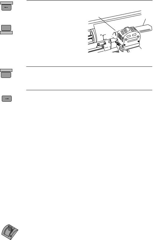
• TOF SET
TOF SET
PARK
+
ENTER
ALT
• SETUP
BIN
EXIT
SETUP
• QUALITY
QUALITY
3. Control panel and operations
(ALT+PARK keys)
The TOF SET key is valid only when paper is loaded. When the TOF SET key is pressed in the offline state, the TOF position is set to the top of the
r i b b o n g u i d e , a n d t h e b u z z e r sounds.
After two seconds, the paper is fed backward so that the TOF p o s i t i o n i s a t t h e c u r r e n t
printing position.
Whe the TOF position is set, the setting of “7 TOF ADJUST” is changed to this set automatically.
Ribbon Guide
|
|
|
|
A |
A |
A |
A |
A |
|
|
|
A |
|
|
|||
|
|
A |
|
|
|
|||
|
A |
B |
|
|
|
|
||
|
B |
|
|
|
|
|||
|
B |
|
|
|
|
|||
0.5 |
B |
C |
C |
|
|
|
|
|
C |
D |
|
|
|
|
|||
C |
D |
|
|
|
|
|||
|
D |
D |
|
|
|
|
|
|
|
|
|
|
|
|
|
|
*TOF:Top of form
When the SETUP key is pressed the printer enters the setup options. The setup options are explained later in the "Basic setup options" section.
This key is for selecting the print quality: LQ, NLQ, HQDR (high quality draft), DRAFT, SD (speed draft), or SSD (super speed draft). To set your d e s i r e d p r i n t q u a l i t y s i m p l y s c r o l l a n d s t o p w h e r e y o u r s e l e c t i o n i s displayed. The printer beeps once for an acknowledgment.
Software commands can override the print quality setting of this key. However, "#26 Quality Lock" option described on page 41 can lock-in the
LCD |
ESC x 1 |
ESC x 0 |
Graphic print speed |
|
LQ is selected |
Draft is selected |
|||
LQ |
LQ |
Draft |
Normal |
|
NLQ |
NLQ |
Draft |
High speed 1 |
|
HQDR |
LQ |
HQDR |
High speed 2 |
|
DRAFT |
LQ |
Draft |
High speed 2 |
|
S.D. |
S.D. |
S.D. |
High speed 2 |
|
S.S.D. |
S.S.D. |
S.S.D. |
High speed 2 |
|
selection by this key and disable software commands.
This key also selects the graphic print speed.
*The graphic print speed is selected only by “31 GRAPHIC QUALITY” in the extended setup options.
•Others
The ← , → , ↓ , ↑ EXIT and ENTER keys become effective only in the setup options entered by pressing the SETUP key. For more information refer to "Basic setup options."
Control Levers
•Head adjustment Lever
1
5
9
This lever adjusts the gap between the print head and the platen. The correct gap adjustment for a different paper thickness is required to obtain optimum print quality. See also page 15.
19

3. Control panel and operations
• Paper Select Lever
The paper select lever serves to switch between the fanfold continuous paper s e t t i n g a n d t h e s i n g l e s h e e t p a p e r s e t t i n g ( o r C S F s e t t i n g w h e n C S F installed).
Note: Switching this lever to continuous paper setting will mechanically release the pressure roller for single sheets and engage gear trains for continuous paper.
Paper parking
This function moves fanfold paper back to the push tractor position (park station) so that single sheet paper can be used. Specifically it is useful when switching from fanfold paper to single sheet paper.
•Pressing the PARK key removes the fanfold paper from the print station so that single sheet paper can be used.
•Switching of the paper select lever is required for the actual mechanical switching of the paper select.
•Pressing the PARK key when the printer is in the paper-out state loads the selected paper (fanfold or single sheet) to the top-of-form position.
The following table explains the paper handling of the PARK key in the offline state:
Friction Lever |
P.OUT Indicator |
Action |
Continuous Paper |
ON |
Autoload the paper (similar to the FF key) |
|
|
|
|
OFF |
Park the paper in the push tractor position |
Single Sheets |
ON |
Autoload the paper (similar to the FF key) |
|
|
|
|
OFF |
Eject the paper (similar to the FF key) |
|
|
|
Notes
1.Make sure that the setting of the paper select lever corresponds to the type of paper being used.
2.The paper park function causes PAPER ERROR in the following situations:
a)when the fanfold paper is not set in the park station (at the push tractors) after moving more than 22 inches backward.
b)when the paper (fanfold or single sheet) is not autoloaded to the print station after feeding more than 8 inches. (At this time, the printer tries to sense the paper in the printer.)
c)when single sheet paper is not ejected from the printer after advancing more than 22 inches.
20

3. Control panel and operations
Printing test pattern
Before performing the printer's self test, be sure the ribbon cassette and paper are properly installed in the printer. The self test prints a continuous pattern of printable characters (ASCII character pattern) in either draft or letter quality (LQ).
While test printing is executed, the ON LINE lamp blinks and the LCD indicates “SELF TEST”.
SELF TEST DRAFT
RESET
TOF SET |
|
|
|
|
POWER |
|
|
|
|
|
ON LINE |
PARK |
QUALITY |
M.LF |
LF |
FF |
P.OUT |
BIN |
|
|
|
|
|
EXIT |
ENTER |
|
|
|
|
SETUP |
ALT |
M.RLF |
RLF |
TEAR OFF |
ON LINE |
To run the draft self test
Press the LF key while turning ON the printer's power. If the printer is already turned ON, the draft self test may be performed by pressing the LF key together with the RESET key.
Keep pressing the LF key until the self test begins.
To run the LQ self test
Press both the LF and ON LINE keys simultaneously while turning ON the printer. If the
printer is already turned ON, the LQ self test may be performed by pressing both the LF and
ON LINE keys simultaneously together with the RESET key.
Keep pressing the LF and ON LINE keys until the self test begins.
To stop the self test temporarily
Press the ON LINE key to stop printing.
To resume the self test
Press the ON LINE key again to restart printing.
To terminate this function
Press the RESET key or turn off the power.
Note
Before initiating the self test, make sure that the width of the paper, especially fanfold paper loaded in the printer corresponds to the setting selected in the extended setup options.
44 PAPER WIDTH
|
|
|
|
|
Maximum printable columns at 10cpi |
||
|
WIDTH: |
15 |
IN |
|
.................... |
136 columns |
|
|
|
|
80 columns |
||||
|
WIDTH: |
10 |
IN |
|
.................... |
||
|
|
|
36 columns |
||||
|
WIDTH: |
5 |
IN |
|
.................... |
||
|
|
|
|
|
|||
|
|
|
|
|
|
|
|
21
3. Control panel and operations
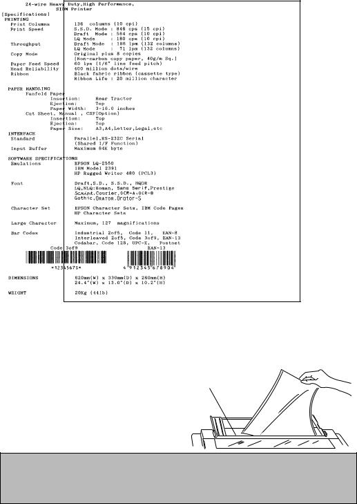
Demonstration print-out
To see what this printer can do, you may run this demonstration print-out (Letter or A4 paper size) for checking the printer's performance. Press and hold the RLF and the M.RLF keys while turning on the printer's power.
Tearing off a form
(Used only with fanfold continuous paper)
T h i s f u n c t i o n i s a c t i v a t e d b y t h e TEAR OFF k e y a n d f e e d s f a n f o l d p a p e r s o t h a t t h e perforation is aligned with the paper cutter located at the top rear of the printer, thus enabling simple paper tearing . During the tear off
operation, the M.LF, and M.RLF keys are used to correctly align the paper to the paper cutter.
A f t e r t e a r i n g o f f t h e f o r m , p r e s s i n g t h e T E A R O F F k e y a s e c o n d t i m e r e v e r s e l y f e e d s t h e p a p e r t o t h e t o p o f t h e n e x t available form.
Note
Pressing the TEAR OFF key (or the ONLINE key) the second time may return the paper to the original print position when the top edge of the form does not pass above the paper location prior to the first TEAR OFF operation.
22
 Loading...