


DAYTONA 2 USA DELUXE TYPE
R
R
R
R
R
R
Page 1 of 2Table Of Contents Daytona 2 st
d
DAYTONA 2 USA STD
INTRODUCTION TO THE OWNER'S MANUAL 1
GENERAL PRECAUTIONS 2~3
1. PRECAUTIONS TO BE HEEDED FOR OPERATION 4~5
2. NAME OF PARTS 6
3. ACCESSORIES 7~8
4. ASSEMBLY AND INSTALLATION 9~15
5. PRECAUTIONS TO BE HEEDED FOR WHEN
MOVING MACHINE
6. CONTENTS OF GAME 17~21
7. EXPLANATION OF TEST AND DATA DISPLAY 22~32
7-1 SWITCH UNIT AND COIN METE
7-2 TEST MODE 24
7-3 MEMORY TEST 24
7-4 T.G.P. TEST 25
7-5 INPUT TEST 26
7-6 OUTPUT TEST 26
7-7 SOUND TEST 27
7-8 C.R.T. TEST 27
7-9 GAME ASSIGNMENTS 28
7-10 COIN ASSIGNMENTS 29~31
7-11 BOOKKEEPING 32
7-12 BACKUP DATA CLEA
8. HANDLE MECHA 33~37
8-1 REMOVING THE CONTROL PANEL 33~34
8-2 REPLACING AND ADJUSTING THE HANDLE'S
V.R.
8-3 GREASING 36
8-4 SWITCH REPLACEMENT 37
9. SHIFT LEVE
9-1 REMOVING THE SHIFT LEVE
9-2 SWITCH REPLACEMENT 39~40
10. ACCEL & BRAKE 41~46
10-1 ADJUSTMENT AND REPLACEMENT OF
VOLUME
10-2 GREASING 43~44
11. COIN SELECTO
12. MONITO
TABLE OF CONTENTS
16
23
32
35
38~40
38~39
41~42
47~49
50~63
12-1 PRECAUTIONS TO BE HEEDED WHEN
50
7/12/2005http://www.sauservice.com/manuals/Daytona2_html/day2stdtoc.html
HANDLING MONITO
R
R
R
R
R
d
12-2 CLEANING THE CRT SURFACES 51~53
13. REPLACEMENT OF FLUORESCENT LAMP AND
LAMPS
13-1 REPLACEMENT OF FLUORESCENT LAMP 54
14. PERIODIC INSPECTION TABLE 55
15. TROUBLESHOOTING 56
15-1 REPLACEMENT OF FUSES 57
16. GAME BOARD 68~69
16-1 REMOVING THE IC BOARD 70
16-2 COMPOSITION OF GAME BOARD 71
17. DESIGN RELATED PARTS 72~73
18. PARTS LIST 74~124
TOP ASSY DAYTONA 2 STD 74~75
ASSY BILLBOARD STD 76~77
ASSY COIN CHUTE TOWE
ASSY SW UNIT 79
AC UNIT 80
ASSY MONITOR COVER (BOTH SIDES) 81
ASSY SPEAKE
ASSY VIRTUAL BUTTON 83~84
ASSY BASE BOX 85
MAIN BASE 86
ASSY SEAT 87~88
ASSY WOOFE
ASSY 4 SPEED SHIFTE
ASSY ACCEL&BRAKE 91~92
ASSY HANDLE MECHA 93~95
ASSY SOUND BD 96
ASY SHIELD CASE 97~98
ASSY MAIN BD 99~100
ASSY ELEC BASE 101
ASSY DRIVE BD 102~103
ASSY COCKPIT 104~105
ASSY CONTROL PANEL 106~107
ASSY MAIN BASE 1P 108
19. WIRING DIAGRAMS XXX
54
78
82
89
90
Page 2 of 2Table Of Contents Daytona 2 st
7/12/2005http://www.sauservice.com/manuals/Daytona2_html/day2stdtoc.html

p
Page 1 of 2Intro
[Previous page][Next page][Table of Contents]
INTRODUCTION OF THE OWNERS MANUAL
SPECIFICATIONS
Installation space: 68 in.(L) x 45 in.(W)
Height: 70 in.
Weight: Approx. 570 lbs.
Power maximum current: 8.4 Amp AC 120V 60 Hz
MONITOR: 50 INCH PROJECTION DISPLAY
SEGA ENTERPRISES, LTD., has for more than 30 years been supplying various innovative and
opular amusement products to the world market. This Owners Manual is intended to provide detailed
descriptions together with all the necessary installation, game settings and parts ordering information
related to the SEGA DAYTONA 2 STD, a new SEGA product.
This manual is intended for those who have knowledge of electricity and technical expertise, especially
in ICs, CRTs, microprocessors, and circuit boards. Read this manual carefully to acquire sufficient
knowledge before working on the machine. Should there be a malfunction, non-technical personnel
should under no circumstances touch the interior system. Should the need arise, contact our main office,
or the closest branch office listed below.
7/12/2005http://www.sauservice.com/manuals/Daytona2_html/introday2std.html

SEGA ENTERPRISES, INC. (USA)
Page 2 of 2Intro
Customer Service
45133 Industrial Drive
Fremont, CA 94538
Phone 650-802-1750
Fax 650-802-1754
7:30 am - 4:00 pm, Pacific Standard Time
Monday thru Friday
7/12/2005http://www.sauservice.com/manuals/Daytona2_html/introday2std.html

Page 1 of 3General Precautions
General Precautions
[Previous page][Next page][Table of Contents]
Follow Instructions: All operating and use instructions should be followed.
Attachments: Do not use attachments not recommended by the product manufacturer as they may cause
hazards.
Accessories: Do not place this product on an unstable cart, stand, tripod, bracket, or table. The product
may fall, causing serious injury to a child or adult, and serious damage to the product. Use only with a
cart, stand, tripod, bracket, or table recommended by the manufacturer, or sold with the product. Any
mounting of the product should follow the manufacturer's instructions, and should use only mounting
accessories recommended by the manufacturer.
Moving the Product: This product should be moved with care. Quick stops, excessive force, and uneven
surfaces may cause the product to overturn.
Ventilation: Slots and openings in the cabinet are provided for ventilation, to ensure reliable operation of
the product and to protect it from overheating; these openings must not be blocked or covered. The
openings should never be blocked by placing the product in a built-in installation such as a bookcase or
rack unless proper ventilation is provided or the manufacturer's instructions have been adhered to.
Power Sources: This product should be operated only from the type of power source indicated on the
marking label. If you are not sure of the type of power supply to your location, consult your local power
company. For products intended to operate from battery power or other sources, refer to the operating
instructions.
Grounding or Polarization: This product is equipped with a three-wire grounding-type plug, a plug
having a third (grounding) pin. This plug will only fit into a grounding-type power outlet. This is a
safety feature. If you are unable to insert the plug into the outlet, contact your electrician to replace your
obsolete outlet. Do not defeat the safety purpose of the grounding-type plug.
Power Cord Protection: Power-supply cords should be routed so that they are not likely to be walked on
or pinched by items placed upon or against them, paying particular attention to cords at plugs,
convenience receptacles, and the point where they exit from the product.
Overloading: Do not overload wall outlets, extension cords, or integral convenience receptacles as this
can result in a risk of fire or electric shock.
Object and Liquid Entry: Never push objects of any kind into this product through openings as they may
touch dangerous voltage points or short-out parts that could result in a fire or electric shock. Never spill
liquid of any kind on the product.
7/12/2005http://www.sauservice.com/manuals/Daytona2_html/gpday2std.html

p
p
Page 2 of 3General Precautions
Servicing: Do not attempt to service this product yourself as opening or removing covers may expose
you to dangerous voltage or other hazards. Refer all servicing to qualified service personnel.
Damage Requiring Service: Unplug this product from the wall outlet and refer servicing to qualified
service personnel under the following conditions:
a) If the power cord or plug is damaged;
b) If liquid has been spilled, or objects have fallen into the product;
c) If the product has been exposed to rain or water;
d) If the product does not operate normally when following the operating instructions. Adjust only those
controls that are explained in the operating instructions. An improper adjustment of other controls may
result in damage and will often require extensive work by a qualified technician to restore the product to
its normal operation;
e) If the product has been dropped or damaged in any way;
f) When the product exhibits a distinct change in performance, this indicates a need for service.
Replacement Parts: When replacement parts are required, be sure the service technician has used
replacements parts specified by the manufacturer or that have the same characteristics as the original
art. Unauthorized substitutions may result in fire, electric shock, or other hazards.
Safety Check: Upon completion of any service or repairs to this product, ask the service technician to
erform safety checks to determine that the product is in proper operating condition.
Heat: The product should be situated away from heat sources such as radiators, heat registers, stoves, or
other products (including amplifiers) that produce heat.
Lithium Battery- Dispose of batteries only in accordance with the battery manufacturer's
recommendations. Do not dispose in an open flame condition, since the battery may explode.
Cleaning: When cleaning the monitor glass, use water or glass cleaner and a soft cloth. Do not apply
chemicals such as benzene, thinner, etc.
Location: This an indoor game machine, DO NOT install it outside. To ensure proper usage, avoid
installing indoors in the places mentioned below:
· Places subject to rain/water leakage, or condensation due to humidity;
· In close proximity to a potential wet area;
· Locations receiving direct sunlight;
· Places close to heating units or hot air;
·In the vicinity of highly inflammable/volatile chemicals or hazardous matter;
7/12/2005http://www.sauservice.com/manuals/Daytona2_html/gpday2std.html

· On sloped surfaces;
I
Reg
· In the vicinity of emergency response facilities such as fire exits and fire extinguishers;
· Places subject to any type of violent impact;
· Dusty places.
Page 3 of 3General Precautions
nstallation Precautions
· Verify the amperage of the branch circuit outlet before plugging in the power plug. Do not overload the
circuit.
· Avoid using an extension cord. If one is required, use an extension cord of type SJT, 16/3 AWG rated
min. 120 VAC, 7A.
· Moving this unit requires a minimum clearance (of doors, etc.) of 32" (W) by 77" (H).
· For the operation of this machine, secure a minimum area of 32" (W) by 42"(D).
ulatory Approvals
This game has been tested and found to comply with the Federal Communications Commission Rules.
This device complies with Part 15 of the FCC Rules. Operation is subject to the following two
conditions: (1) This device may not cause harmful interference, and (2) this device must accept any
interference received, including interference that may cause undesired operation.
This game has been tested and listed by Underwriters Laboratories, Inc., to ANSI/UL22.
7/12/2005http://www.sauservice.com/manuals/Daytona2_html/gpday2std.html

g
Page 1 of 3Precautions to be heeded during operation.
[Previous page][Next page][Table of Contents]
1 . PRECAUTIONS TO BE HEEDED FOR OPERATION
In order to avoid accidents, check the following before starting the operation:
Check if all of the adjusters are in contact with the surface. If they are not, the cabinet
can move and cause an accident.
Check to see if hazard preventive parts are damaged or omitted.
Operating the product with the hazard preventive parts as is left in an irregular status
will cause accidents.
Do not put any heavy item on this product. Placing any heavy item on the product can cause a
falling down accident or parts damage.
Do not climb on the product. Climbing on the product can cause falling down accidents.
To check the top portion of the product, use a step.To avoid electric shock, check to see if door &
cover parts are closed.
To avoid electric shock, short circuit and or parts damage, do not put the following items on or in
the periphery of the product:
Flower vases, flower pots, cups, water tanks, cosmetics, and receptacles/containers/vessels
containin
chemicals and water.
7/12/2005http://www.sauservice.com/manuals/Daytona2_html/1day2std.html

Page 2 of 3Precautions to be heeded during operation.
In order to prevent accidents, be sure to comply with the following points before and during
operation.
To avoid injury, be sure to provide sufficient space by considering the potentially crowded
situation at the installation location. Insufficient installation space can cause the player to come
into contact with or hit the others and result in injury or trouble.
PRECAUTIONS TO BE HEEDED DURING OPERATION
To avoid injury and trouble, be sure to constantly give careful attention to the behavior
and manner of the visitors and players.To avoid injury and accidents, those who fall
under the following categories are not allowed to play the game.
> Intoxicated persons.
> Those who need assistance such as the use use of apparatus when walking.
> Those who have high blood pressure or a heart condition.
> Those who have experienced muscle convulsion or loss of consciousness when exposed to
intensive light stimulus due to watching television, playing video games or water surface
flickering.
> Persons susceptible to motion sickness.
> Persons whose actions runs counter to the product's warning displays.
To avoid injury from potential falling down accidents, be sure to that only one person is
allowed to play at a time.
Do not allow players to put any heavy items or beverages on the product. Falling items
can cause accidents and spilled beverages can cause electric shock.
To avoid electric shock and short circuit, do not allow customers to put hands and fingers or
extraneous matter in the openings of the product or small openings in or around the doors.
To avoid falling down and injury resulting from falling down, immediately stop the customer's
leaning against or climbing on the product, etc.
To avoid electric shock and short circuit, do not allow the customers to unplug the power plug
without justifiable reason.
Instruct the player to hold firmly to the Safety Bar during game. Caution the customers
who are most likely to cause injury by playing without holding the Safety Bar, for
example.
7/12/2005http://www.sauservice.com/manuals/Daytona2_html/1day2std.html

p
Page 3 of 3Precautions to be heeded during operation.
To avoid injury, do not allow persons other than the player access to the mechanism base during
game play.
Instruct the player not to put baggage, etc. on the mechanism base to avoid damaging such items.
Regarding this product, the weight of the player is limited to 330 lbs. To avoid machine damage
and injury due to machine damage, playing by those who are as heavy as 330 lbs. or heavier is
strictly prohibited.
Immediately stop violent acts such as hitting and kicking the product. Such violent acts can cause
arts to be damaged or falling down.
7/12/2005http://www.sauservice.com/manuals/Daytona2_html/1day2std.html
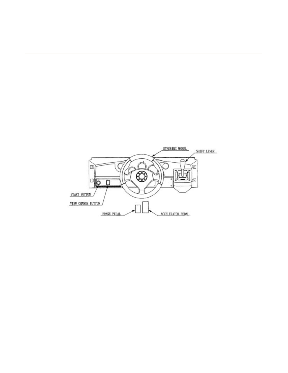
R
N
ame Of Parts
Page 1 of 2
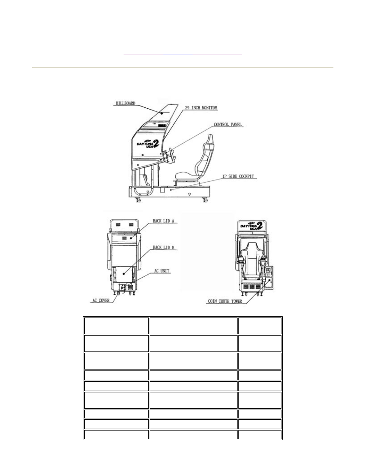
2. NAME OF PARTS
[Previous page][Next page][Table of Contents]
GAME
SPECIFICATIONS
DURING
SHIPPING
BILLBOARD
COCKPIT
COIN CHUTE
TOWE
BILLBOARD
WIDTH ~ LENGTH ~
HEIGHT
All measurements are in
inches
620 LBS.
56" X70" X58"
47" X36" X78"
15" X 24" X 26" 40 LBS
42" X23" X22"
WEIGHT
40 LBS.
540 LBS.
33 LBS.
7/12/2005http://www.sauservice.com/manuals/Daytona2_html/NOPday2std.html

R
N
ame Of Parts
Page 2 of 2
COCKPIT
COIN CHUTE
TOWE
WHEN
ASSEMBLED
57" X82" X57"
12.5" X 21" X 24" 33 LBS
52" X 112" X 90"
513 LBS.
579 LBS.
7/12/2005http://www.sauservice.com/manuals/Daytona2_html/NOPday2std.html
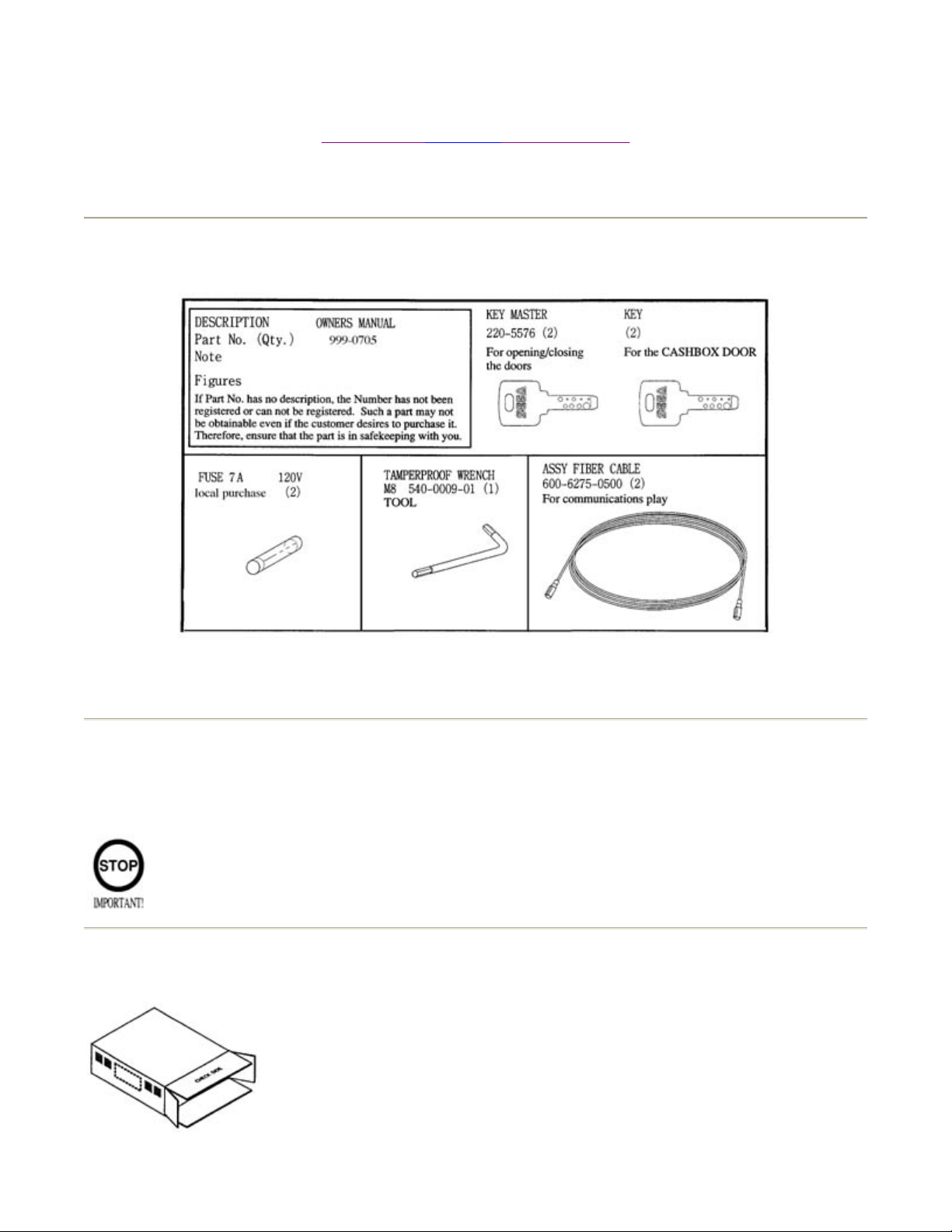
Page 1 of 2Accessories
Please read entire page as it contains information regarding your warranty.
3. ACCESSORIES
[Previous page][Next page][Table of Contents]
!!!Shipment of model 3 Board!!!
When asking for the replacement or repair of the product's Game Board (MODEL 3
BOARD), be sure to put the Game Board together with the Shield Case in the Carton
Box.
Carton Box
601-8928 (1)
Used for transporting
7/12/2005http://www.sauservice.com/manuals/Daytona2_html/2day2std.html
g
Page 2 of 2Accessories
Refer to the following.
the Game board.
Wrap the Shield Case with the packaging material and put it in the Carton Box as
shown. Putting it upside down or packing otherwise in the manner not shown can
dama
e the Game Board and parts.
7/12/2005http://www.sauservice.com/manuals/Daytona2_html/2day2std.html
N
Page 1 of 2Assembling and Installation
[Previous page][Next page][Table of Contents]
4 . ASSEMBLING AND INSTALLATION
Assembling should be performed as per this manual. Since this is a complex machine,
erroneous assembling may cause damage to the machine, or malfunctioning to occur.
When assembling, be sure to perform work by plural persons.
Depending on the assembly work, there are some cases in which performing the work by a single
person can cause personal injury or parts damage.
When installing the billboard, it is difficult to carry out work by one person. To
perform work properly and safely, be sure work is performed by at least two people.
ote that the tools such as a phillips screwdriver and wrench for M16 hexagon bolt w/24 mm width
across flats are required for the assembly work.
When carrying out the assembly work, follow the procedure in the following 6-item sequence:
1. ASSY OF REAR CABINET (COCKPIT)
2. ASSY OF BILLBOARD
3. SECURING IN PLACE (ADJUSTER ADJUSTMENT)
4. POWER SUPPLY
5. TURNING POWER ON
7/12/2005http://www.sauservice.com/manuals/Daytona2_html/3day2std.html

N
Page 2 of 2Assembling and Installation
6. ASSEMBLING CHECK
To perform work safely and securely, be sure to prepare a step which is in a secure and stable condition.
ot using a step or using an unstable step can cause a violent falling down accident.
7/12/2005http://www.sauservice.com/manuals/Daytona2_html/3day2std.html
p
recaution to be heeded when moving the machine
Page 1 of 2
[Previous page][Next page][Table of Contents]
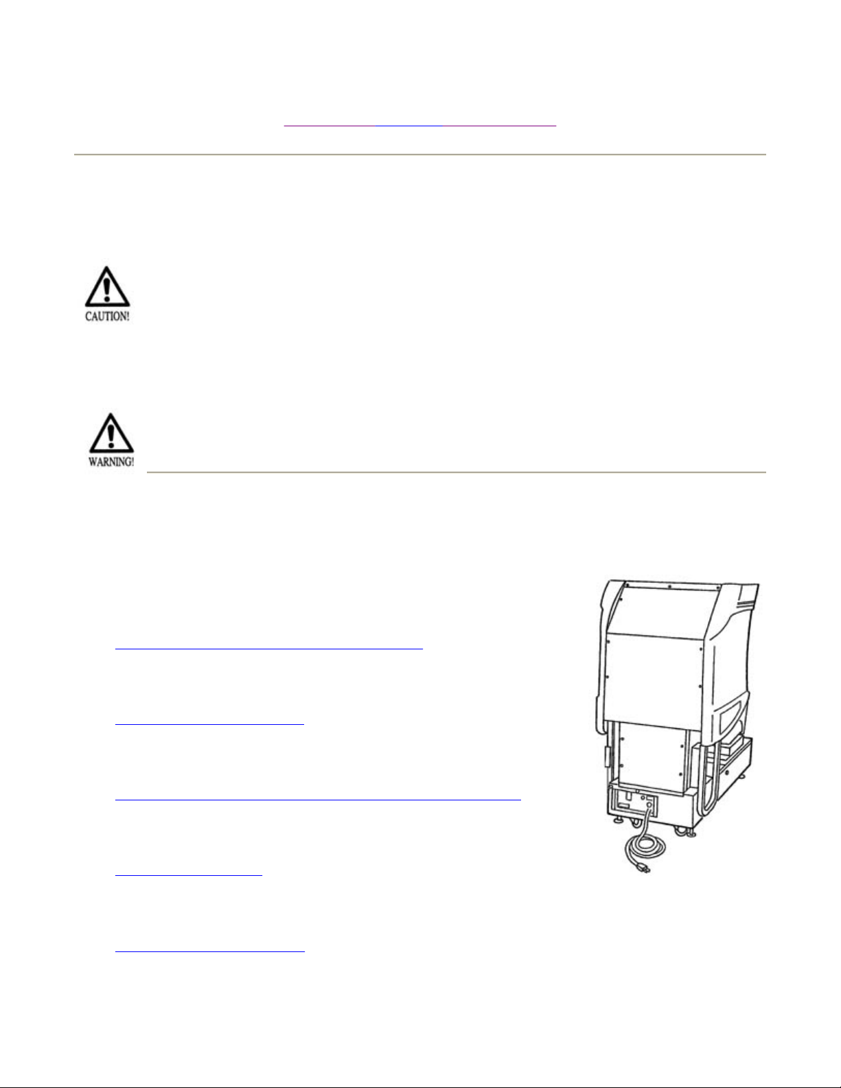
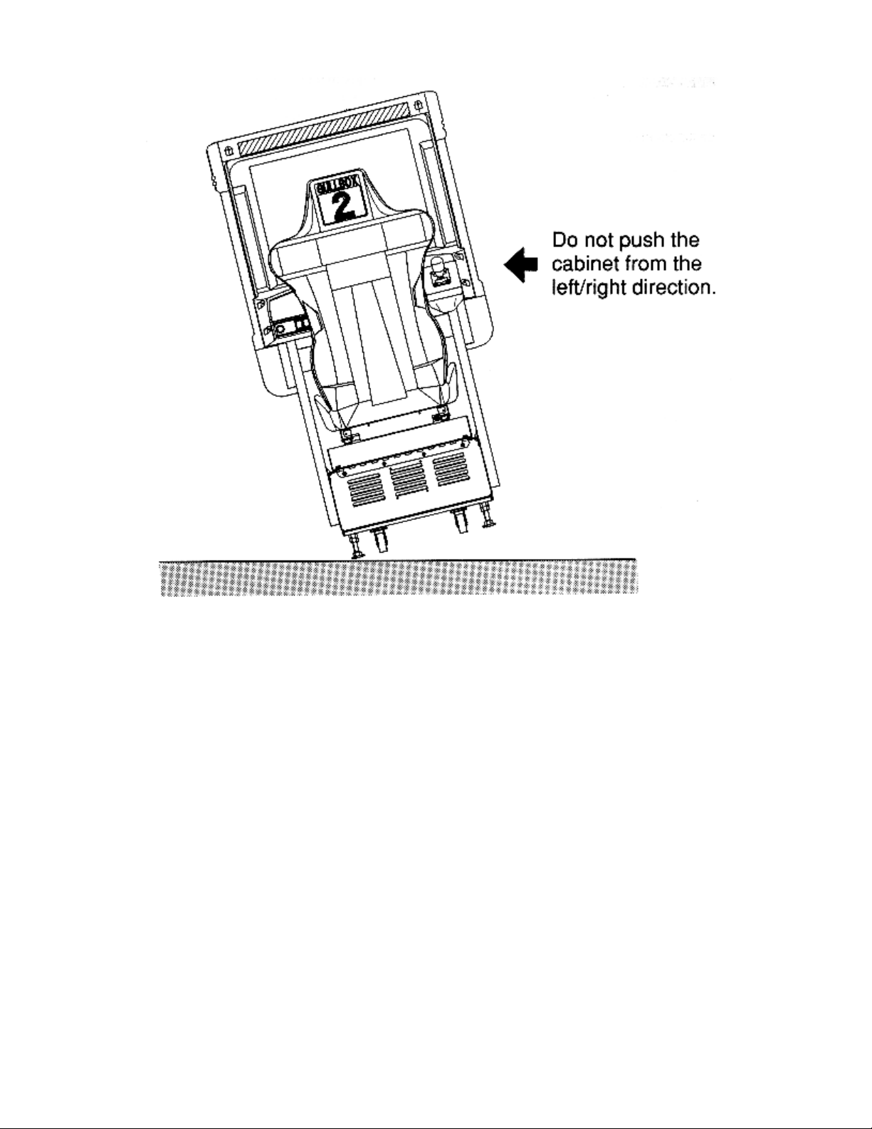
5. PRECAUTIONS TO BE HEEDED WHEN MOVING THE MACHINE
When moving the machine, be sure to pull out the plug from the power supply. Moving the
machine with the plug as is inserted can damage the power cord and cause a fire or electric shock.
When moving the machine on the floor, retract the Adjusters and ensure that Casters
make contact with the floor. During transportation, pay careful attention so that
Casters do not tread power cords. Damaging the power cords can cause an electric
shock and/or short circuit.
When lifting the cabinet, be sure to hold the catch portions or bottom part. Lifting the cabinet by
holding other portions can damage parts and installation portions, due to the empty weight of the
cabinet, and cause personal injury.
Use care when handling glass made parts. When the glass is damaged, fragments of glass can
cause injury.
7/12/2005http://www.sauservice.com/manuals/Daytona2_html/9day2std.html
p
recaution to be heeded when moving the machine
Page 2 of 2
7/12/2005http://www.sauservice.com/manuals/Daytona2_html/9day2std.html
p
Page 1 of 3Contents of Game/How to Pla
y
[Previous page][Next page][Table of Contents]
6. CONTENTS OF GAME/HOW TO PLAY
The following explanations apply to the case the product is functioning satisfactorily. Should there be
any moves different from the following contents, some sort of faults may have occurred. Immediately
look into the cause of the fault and eliminate the cause thereof to ensure satisfactory operation.
During the ADVERTISE MODE, the View Change Button Lamp lights up periodically. When the
roduct is energized, the Billboard's Fluorescent lamp is always lit. The Leader Lamp (below the
fluorescent lamp) flashes periodically. During the ADVERTISE MODE, sound is emitted from all of the
speakers.
1.) Get in the Cockpit. The seat can be adjusted in forward and rearward positions. The lever is located
on the lower right (facing the screen) of the seat. Pull this Lever to make adjustments.
2.) Insert a coin(s). Number of coins is displayed on the lower left of the screen. Inserting one play
worth of coin(s) causes the SELECT screen to be displayed. Up to 9 credits can be counted at one time.
Coins inserted after counting 9 credits will neither be counted nor returned. Credits will not be displayed
in the SELECT mode and during the game play (credits are displayed only during the ADVETISE
MODE).
3.) When a coin is inserted to one of the machines linked for communication, the other unit's screen will
be in the entry accepting mode, and countdown starts. For Entry, the player is to insert a coin(s) during
countdown.
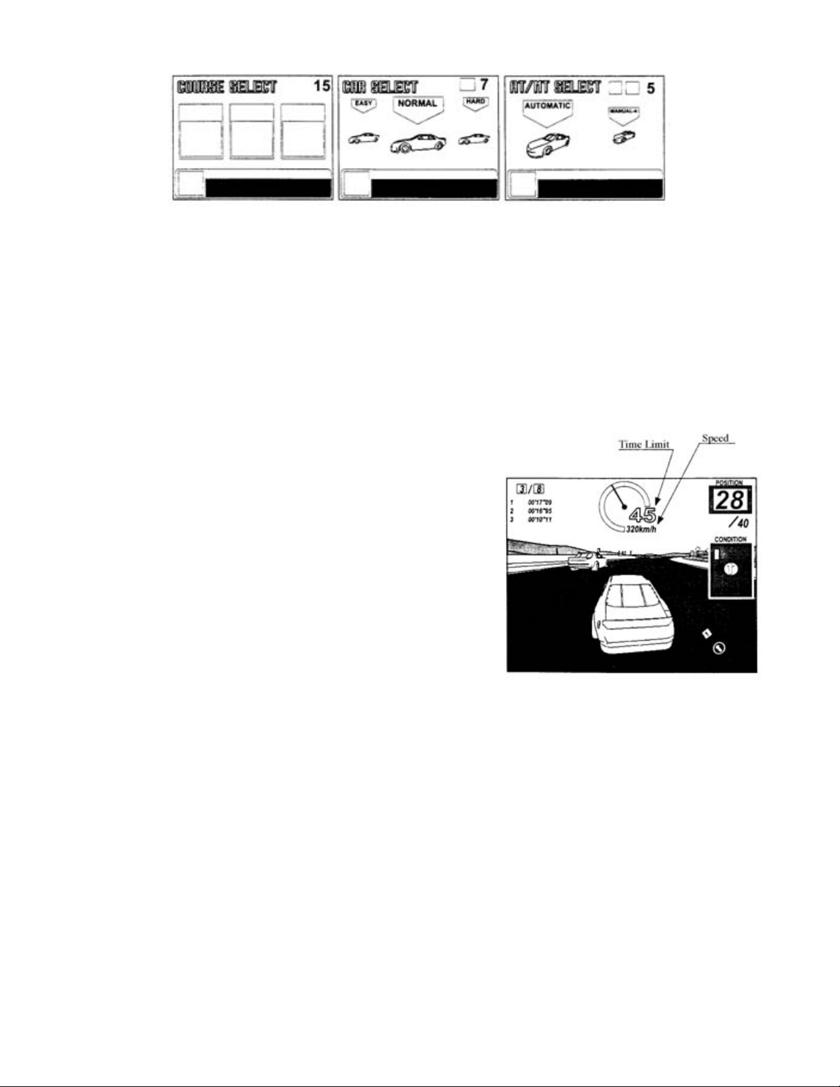
4.) Select sequentially in order of COURSE, CAR, and TRANSMISSION. turn the Steering Wheel to
choose an decide the selection by stepping on the Accelerator Pedal.
7/12/2005http://www.sauservice.com/manuals/Daytona2_html/10day2std.html
)
Page 2 of 3Contents of Game/How to Pla
y
COURSE SELECT / CAR SELECT / TRANSMISSION SELECT
Display the SELECT mode starts countdown. When the countdown becomes 0, the COURSE and CAR
being chosen are determined automatically.
Stepping on the Accel. Pedal again after stepping on it once will have the present SELECT screen, in the
middle of the counting down, proceed to the next select screen.
Course selection is decided by majority. In case of a tie, the left-hand side of course on the SELECT
screen has priority.
5.) Choosing and deciding on either Automatic or Manual (4
shifts) will result in a race start. At this time, while pressing the
Start Button, step on the Accel. Pedal to decide on the selection
to play in the PLAYER ONLY mode.
After race start, the View Change button being selected lights
up. While participating in the race, if the player becomes the
leader, that particular seat's Leader Lamp flashes. The Steering
Wheel is subjust to the reaction and load depending on the
status of the Course, Course Out and Crash.
6.) The number of Laps displayed on the upper left of the
screen, and lap Time is shown below the upper left.
Tachometer and Time Limit (remaining time) as well as Speed are shown on the upper center portions.
Position, Condition and Course Map are displayed sequentially in order from the upper right portion of
the screen downward. If Manual Transmission is selected, Gear Position will be shown to the right side
of Speed.
7.) Simultaneously with race start, the Time Limit decreases. Passing a Course's Check Point allows the
game to be continued with the remaining time of the previous section added to the Time Limit up to the
next Check Point. Failing to pass the Check Point within the Time Limit results in GAME OVER.
8.) When the race participent's leader finishes the specified number of laps of each course, the game is
then over. The game is over also when all of the race participents fail to pass the checkpoint within the
Time Limit.
9.) After one game is finished, if credits allowing for play still remain, the SELECT mode appears on
the screen.
Excellent players can enter his name. Select name characters by turning the Steering Wheel
10.
7/12/2005http://www.sauservice.com/manuals/Daytona2_html/10day2std.html

clockwise or counterclockwise and decide by stepping on the Accel. Pedal.
y
Page 3 of 3Contents of Game/How to Pla
7/12/2005http://www.sauservice.com/manuals/Daytona2_html/10day2std.html
Page 1 of 2Explanation of Test and Data Displa
y
[Previous page][Next page][Table of Contents]
7. EXPLANATION OF TEST AND DATA DISPLAY
By operating the switch unit, periodically perform tests and data check. When installing the
machine initially or collecting cash, or when the machine does not function correctly,
perform checking in accordance with the explanations given in this section. The following
shows tests and modes that should be utilized as applicable.
CAUTIONS TO BE HEEDED WHEN USING TEST MODE:
In the case where multiple units are linked for communication play, exiting from the
test mode causes the unit to perform the network check automatically. During this
time, all of the linked units will not allow the game to be played in normal status.
Therefore, be sure not to enter the test mode if any one of the units is in play. on the
other hand, if even one unit is in the test mode, make sure that other machines are not
in play. In this product, the power-on check is performed when the Test Mode is
exited, as when turning power on. Do not touch the Steering Wheel unitl it stops
automatically. touching before it stops may not allow for saticfactory reaction of
Steering Wheel during game play.
ITEMS
INSTALLATION
OF MACHINE
MEMORY
DESCRIPTION
When the machine is installed, perform the following:
1.> Check to see that each setting is as per standard
setting made at time of shipment.
2.> In the INPUT TEST mode, check each SW and
VR.
3.> In the OUTPUT TEST mode, check each of the
lamps.
4.> In the MEMORY TEST mode, check the IC's on
the IC Board.
Choose MEMORY TEST in the MENU MODE to
allow the MEMORY TEST to be performed. In this
test, PROGRAM RAM's, ROM's, and IC's on the IC
Board are checked.
Periodically perform the following:
SECTIONS
7 - 9, 7- 10
7 - 5
7 - 6
7 - 3, 7 - 4
7 - 3, 7 - 4
7 - 3, 7 - 4
1.> MEMORY TEST.
7 - 9, 7 - 10
7/12/2005http://www.sauservice.com/manuals/Daytona2_html/11day2std.html
Page 2 of 2Explanation of Test and Data Displa
y
PERIODIC
SERVICING
CONTROL
SYSTEM
PROJECTOR
IC BOARD
DATA CHECK
2.> Ascertain each setting.
3.> In the INPUT TEST mode, test the control device.
4.> In the OUTPUT TEST mode, check each of the
lamps.
1.> In the INPUT TEST mode, check each SW and
VR.
2.> Adjust or replace VR and SW.
3.> If the problem can not be solved yet, check the
CONTROL's moves.
In the PROJECTOR ADJUSTMENT mode, check to
see if the PROJECTOR adjustment is appropriately
made.
1.> MEMORY TEST.
2.> In the SOUND TEST mode, check the sound
related ROM's.
Check such data as game play time and histogram to
adjust the difficulty level, etc.
7 - 5
7 - 6
7 - 5
8
8
7 - 8
7 - 7
7 - 12
7/12/2005http://www.sauservice.com/manuals/Daytona2_html/11day2std.html
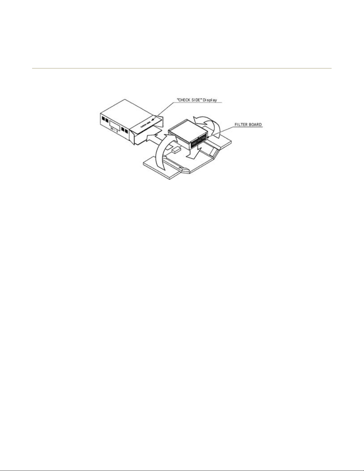
Page 1 of 2Switch Unit and Coin Mete
r
[Previous page][Next page][Table of Contents]
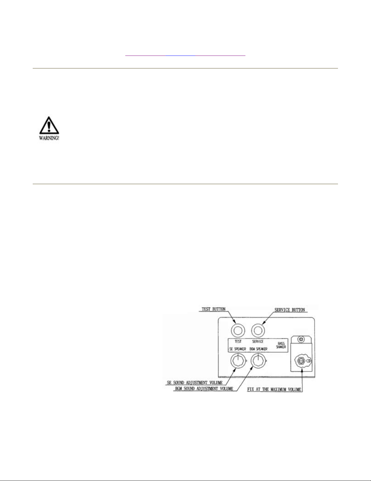
7 - 1 SWITCH UNIT AND COIN METER
Never touch places other than those specified. Touching places not specified can cause
electric shock and short circuit.
Adjust to the optimum sound volume by considering the environmental requirements of
the installation location.
If the COIN METER and the game board are electrically disconnected, game play is not possible.
Open COIN CHUTE DOOR, and the switch unit shown appears. The function of each
switch is as follows:
SWITCH UNIT
(1) SOUND VOLUME
Controls the speaker volume
of the right/left speakers.
(2) TEST BUTTON (TEST SW)
For the handling of the TEST
BUTTON,
refer to the section on test mode.
(3) SERVICE BUTTON (SERVICE
SW)
Gives credits without registering on the coin
meter.
7/12/2005http://www.sauservice.com/manuals/Daytona2_html/12day2std.html

Page 2 of 2Switch Unit and Coin Mete
r
COIN METER
Open Cash Box Door and the Coin Meter will appear. The Coin Meter counts the number of
coins inserted
7/12/2005http://www.sauservice.com/manuals/Daytona2_html/12day2std.html
Page 1 of 6Test Mode
7 - 2 TEST MODE
[Previous page][Next page][Table of Contents]
This mainly checks if the operation of the game BD is accurate, and allows for COIN
ASSIGNMENTS/GAME ASSIGNMENTS setting and Projector adjustments.
Push the TEST BUTTON to cause the following TEST MENU to appear:
By pushing the SERVICE BUTTON, bring the ">" mark to the desired item and press the
TEST BUTTON. This will select the item to be tested.
After the test is complete, move the ">" mark to "EXIT" and press the TEST BUTTON to
return to game mode.
7 - 3 MEMORY TEST
7/12/2005http://www.sauservice.com/manuals/Daytona2_html/13day2std.html

The MEMORY TEST mode is for checking the on-BD memory IC functioning.
"GOOD" is displayed for normal ICs and "BAD" is displayed for abnormal ICs.
When the test is completed, if the
display is as shown left, it is
satisfactory.
After finishing the test, pressing the TEST BUTTON allows the
MENU MODE to return on the screen.
Page 2 of 6Test Mode
IF THE TEST TIME FOR THE MEMORY TEST EXCEEDS 5 MINUTES THE IC
BOARD MAY BE DEFECTIVE.
7 - 5 INPUT TEST
7/12/2005http://www.sauservice.com/manuals/Daytona2_html/13day2std.html

p
Page 3 of 6Test Mode
Press the TEST BUTTON to have the menu mode
return on the screen.
Using the Decision (SET) button instead of TEST BUTTON will not allow for exiting from
the Input Test Mode. Press the SET BUTTON and SELECT BUTTON (UP).
By opening the Coin Chute Door, insert a coin from the Coin Inlet to check the Coin Chute
Tower.
When INPUT TEST is selected, the MONITOR will show the following, allowing you to
watch the status of each switch and the value of each V.R. of the cabinet to be viewed
On the screen, periodically check the status of each switch & V.R.
By pressing each switch, if the display on the right-hand side of the name of each switch
changes to ON from OFF, the SW and the wiring connections are satisfactory.
PITCH refers to the Switch for the left/right Foot Pedal's UP/DOWN. Normally, this is ON
and stepping on the Pedal's front side causes the Switch to become off.
7 - 6 OUTPUT TEST
Choose OUTPUT TEST to cause the following lower screen to appear. In this test,
check the status of each lamp.Pressing the TEST BUTTON causes "ON" to be displayed
and the corresponding lamp lights up. Pressing the TEST BUTTON again causes "OFF" to
be displayed and the lamp goes off. The Foot Controller is locked with the Slide Lock in the
ON status, and Unlocked to become free with the Slide Lock in the OFF status.
Press the test Button to return to the MENU MODE.
7 - 7 SOUND TEST
This enables sound used in the game to be checked. Sound related memory and each
speaker are checked.
Press the SERVICE BUTTON to bring the arrow to the desired sound item to be tested. SE
refers to sound effects and BGM refers to background music.
Each time the SERVICE BUTTON is pressed, the numeral displayed on the screen counts
and sound is admitted.
u
7/12/2005http://www.sauservice.com/manuals/Daytona2_html/13day2std.html
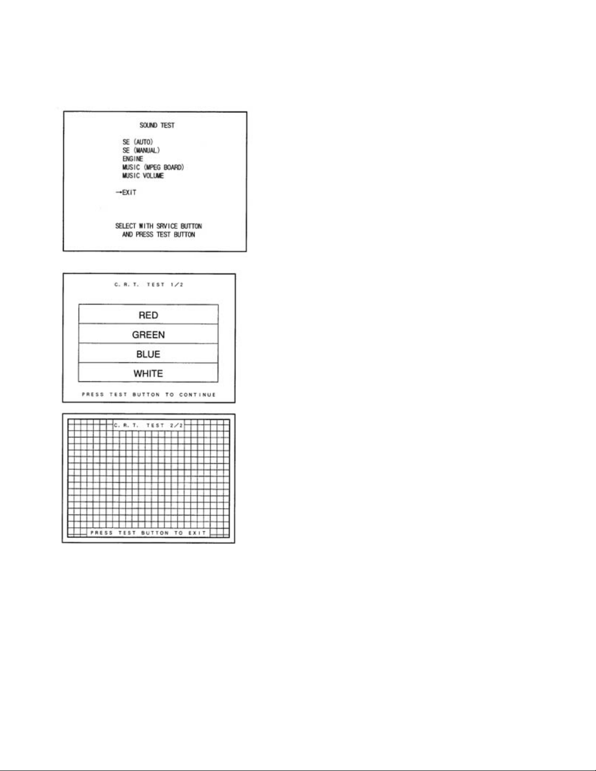
Bring the ">" to EXIT and press the TEST BUTTON to return to the MENU MODE.
Page 4 of 6Test Mode
7 - 8 C.R.T. TEST
Select C.R.T. TEST to cause the MONITOR to
display the screen shown left, allowing MONITOR
adjustment status to be checked.
Periodically check the MONITOR adjustment status
on this screen.
The screen (1/2) enables color adjustment check to be
performed. The color bar of each of the 4 colors,
i.e.,red, green, blue, and white, is the darkest at the
extreme left and becomes brighter towards the
extreme right.
Press the TEST BUTTON to shift to the next screen
(2/2).
The screen (2/2) allows screen size and distortion to
be tested.
Check if the CROSSHATCH FRAME LINE goes out of the screen and if the crosshatch
lines are distorted.
Press the TEST BUTTON to return to the MENU mode. (FIG. 6.2)
7/12/2005http://www.sauservice.com/manuals/Daytona2_html/13day2std.html
p
Page 5 of 6Test Mode
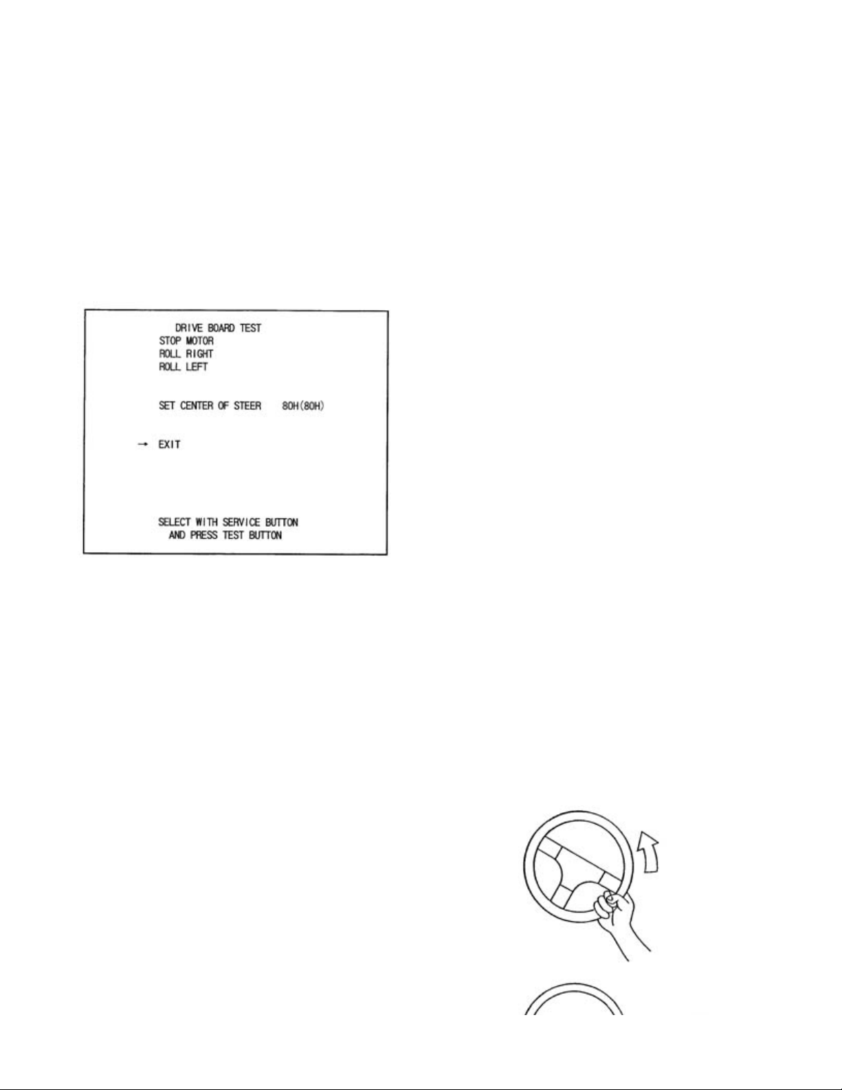
7 - 9 DRIVE BD TEST
Select DRIVE BOARD TEST to have the
following screen displayed. This test allows the
movement of motor, etc., to be checked and the
Steering Wheel Volume setting to be performed.
Press the Service Button to select each item and
press the Test Button to cause the selected item's
movements to be performed.
STOP MOTOR:
Steering wheel and the movements of the Motor
for reaction. As such, intially selecting this item
and pressing the Test Button make no difference
superficially. Select ROLL RIGHT or ROLL LEFT below this item, and in the status that
the motor is functioning ina certain direction, select the item and press the Test Button to
stop movements in that particular direction.
ROLL RIGHT:
ROLL LEFT:
The motor moves so as to turn the Steering Wheel clockwise.
The motor moves so as to turn the Steering Wheel counterclockwise.
Stops the load subjected to the
SETTING THE VOLUME
Performs the setting of VOLUME which detects the
movements of Steering Wheel as per the figure shown below.
When the Steering Wheel Volume is adjusted or replaced,
erforom Volume Setting in the following procedure.
SETTING THE STEERING WHEEL VOLUME
1.) Press the Service button to bring the arrow to SET
CENTER OF STEER.
7/12/2005http://www.sauservice.com/manuals/Daytona2_html/13day2std.html
 Loading...