


20090810 ( SEGA )(CXX_ACXX0V)

Table of Contents
Special note..................................................................................................................... |
3 |
Maintenance and Inspection ........................................................................................... |
3 |
I.Inspection...................................................................................................................... |
3 |
1.Parts list .................................................................................................................. |
4 |
2.Half-Assembly type parts list................................................................................... |
5 |
II.Machine view/size and power rating............................................................................. |
6 |
III.Component description ............................................................................................... |
6 |
IV.Assembly and disassembly ......................................................................................... |
7 |
1. Assembly and disassembly for Assembly type....................................................... |
7 |
2. Assembly and disassembly for Half-Assembly type............................................. |
19 |
3. SET-UP Position & maintenance ................................................................... |
28 |
V.Adjustment and Inspection......................................................................................... |
28 |
1.Link adjustment..................................................................................................... |
29 |
Cable link SET-UP ............................................................................................ |
29 |
Link main board adjustment .............................................................................. |
30 |
2.Adjustment............................................................................................................ |
31 |
SET-UP 1 SET-UP the coin entry price for each game ................................ |
31 |
SET-UP 2 Additional tickets ......................................................................... |
32 |
SET-UP 3 Multiple of tickets......................................................................... |
32 |
SET-UP 4 Game Time SET-UP ................................................................... |
33 |
SET-UP 5 Basket motor AUTO test ............................................................. |
34 |
SET-UP 6 Ball holder motor AUTO test ....................................................... |
34 |
SET-UP 7 Reset the top score 250 or keep the record ................................ |
34 |
SET-UP 8 SET-UP DEMO music ON or OFF ........................................ |
34 |
3.LED Monitor inspection......................................................................................... |
35 |
- 2 - |
|
4.Bookkeep.............................................................................................................. |
35 |
5.Error code ............................................................................................................. |
36 |
VI.How to play ............................................................................................................... |
37 |
1.There are total 4 Stages ....................................................................................... |
37 |
2.2 play types available............................................................................................ |
38 |
VII.Screw and Nut list.................................................................................................... |
38 |
VII.Expended view......................................................................................................... |
40 |
Special note
We want to thank you for choosing our Street basketball machine, and hope you read these instructions first to insure the security of the user before this product is used.
This Manual contains the characteristics, special notes, and a Simple breakdown of the product.
Maintenance and Inspection
■Keep the machine clean by using mild types of cleaners.
■Clean the machine regularly to maintain its appearance.
■The appliance must not be cleaned by a water jet.
■Treat acrylic with care by using Windex
Machine position regulation
The power must be turned off before any movement.
The brake must be released, before the machine is moved.
Do not put the machine under the direct sunlight, it will damage the inside parts.
I.Inspection
Before product use, please confirm the product content first, if anything is missing, please contact us right away.
- 3 -
NO |
Items |
Specification |
Total quantity |
1 |
Chassis items |
Packing |
1 unit |
|
|
|
|
2 |
Street basketball |
No.5 Basketball |
10 unit |
|
|
|
|
3 |
Key |
Maintenance door |
1 pc |
|
|
|
|
4 |
key |
Cash box |
1 pc |
|
|
|
|
5 |
AC cable line |
|
1 unit |
|
|
|
|
6 |
Operation manual |
A4 |
1 set |
|
|
|
|
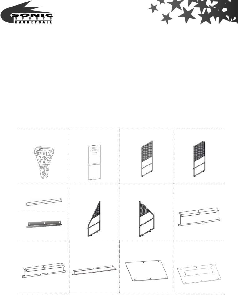
1.Parts list
1B Basket kits |
2A Basket board |
2BR Back right net |
2BL Back left net |
|
|
stander kit |
stander kit |
2C 2 Front net |
3A Front right net |
3B Front left net stander 4A Base holder BF |
stander bridge(short) |
stander kit |
kit |
4D Base holder BB
4B Base holder FB 4C Base holder FF |
5A Wooden base |
5B Ball holder kit |
|
A type |
|
- 4 -

5C Ball guide kits 6A Ball net holder kit |
6B Main part |
6C Block wooden |
|
|
board for motor |
Basketball |
Top cover(optional) Metal Shelf (optional) |
Lower Side Net |
|
|
(Frame Included)×4 |
|
|
(optional) |
2.Half-Assembly type parts list
Main frame |
4B Base holder FB |
4C Base holder FF
Top cover(optional)
5B Ball holder kit
Lower Side Net
(Frame Included)×4 (optional)
- 5 -

5C Ball guide kits |
6A Ball net holder kit |
6B Main part |
6C Block wooden board |
Basketball |
Metal Shelf (optional) |
for motor |
|
|
II.Machine view/size and power rating
Machine Dimensions W1030×D2500×Top cover H2643mm
Weight 260 kg / 558.4 lbs (Accessories not Included )
Top cover 6.6kg Metal Shelf 3.4kg Lower Side Net 4.2kg×4
Voltage AC110V~120V/AC220V~240V(50/60Hz) Use Electrical
plug display as a glide Located behind the machine. Power Consumption 200W
Fuse 2A AC220V~240V / 5A AC110V~120V
Token size φ22mm~27mm
Position direction
Back
Left
Right
III.Component description |
|
Front |
Front |
Top |
Base |
- 6 -

|
Top cover(optional) |
|
Basket board |
Light board display |
|
Basket kit |
LED display(2 figures) |
|
|
||
|
LED display(3 figures) |
|
|
Coin LED display |
|
Metal Shelf |
(2 figures) |
|
|
||
(optional) |
Ticket dispenser |
|
|
||
IC Board |
Coin selector |
|
Power |
Ticket box(inside) |
|
Test Bookkeep |
||
Cash box(inside) |
||
Fuse |
||
|
Bass speaker |
|
Back |
I/O control Board |
Board cover |
|
Basket cover |
|
Light cover |
AC Cable line
Electrical plug display
Lower Side Net
(Frame Included)×4(optional)
Ball holder kit
Side
Main part
IV.Assembly and disassembly
1. Assembly and disassembly for Disassembly type
Step 1
1.Screw Lower Side Net (optional) on the basket board front.
- 7 -
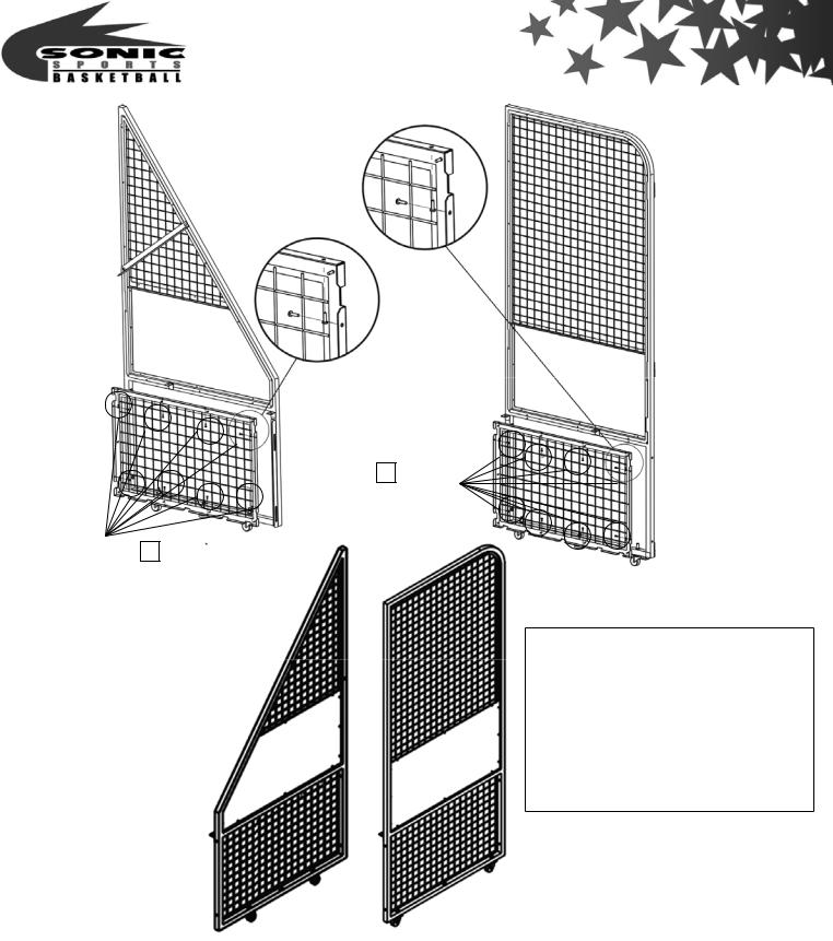
P.35 NO.32 screw(M4×10)×10
P.35 NO.32 screw(M4×10)×10
Assembly parts
2BR |
Back right net stander kit |
2BL |
Back left net stander kit |
3A Front right net stander kit
3B Front left net stander kit
Lower Side Net(Frame Included)
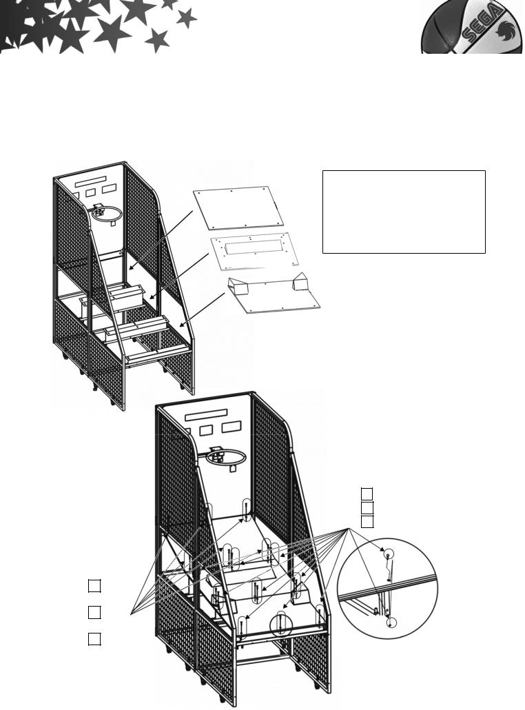
Step 2
1.Screw 1B Basket kits on the basket board front.
- 8 -

Assembly parts
1B Basket kits
2A Basket board
P.34 NO.13 screw(M6×18)×2 screw(M6×16)×2
P.35 NO.21 nut(M6)×4
Step 3
1.Screw 2BR 2BL Back left & right net stander kits on basket board left and right.
2.Screw 2C Front net stander bridge(short) on Back left & Right net stander kits.
-9 -

|
|
Assembly parts |
|
Insert position |
2A |
Basket board |
|
|
|
2BR |
Back right net stander kit |
|
|
2BL |
Back left net stander kit |
|
|
2C |
Front net stander |
|
|
|
bridge(short) |
P.34 |
NO.04 screw (M8×88)×4 |
||
P.35 |
NO.19 nut (M8)×4 |
||
P.34 NO.10 screw (M6×48)×2
P.35 NO.20 nut (M6)×2
Step 4
Assemble 3A 3B Front right & left net stander kit on basket board left and right,
- 10 -
connect with screw & fixed it as drawing.
Insert position
Assembly parts
3A Front right net stander kit
3B Front left net stander kit
P.34 NO.04 screw (M8×88)×4
P.35 NO.19 nut (M8)×4
Step 5
- 11 -
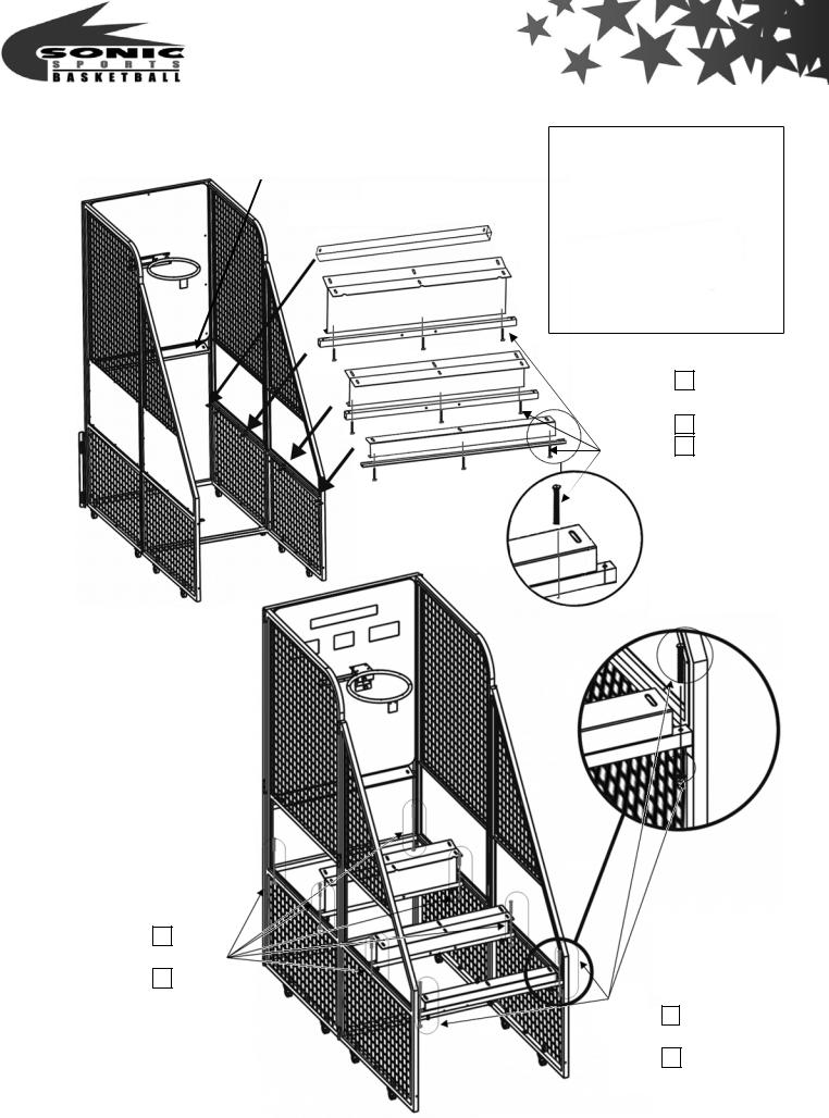
Screw the BF FB FF Base holders & Front net stander bridge(short) step by
step as drawing. |
|
Base holder BB |
Assembly parts |
|
|
2C |
Front net stander |
||
|
|
|
||
|
|
|
||
|
Front net stander bridge(short) |
|
bridge(short) |
|
|
4A |
Base holder BF |
||
|
|
|
||
|
|
|
4B |
Base holder FB |
|
|
|
4C |
Base holder FF |
|
|
BF |
4D |
Base holder BB |
|
|
FB |
|
P.34 NO.10 |
|
|
|
screw (M6×48)×9 |
|
|
|
|
|
|
|
|
|
|
P.35 NO.20 nut (M6)×9 |
|
|
|
|
P.35 NO.30 |
|
|
FF |
|
washer(M6.5×13.5)×9 |
|
|
|
|
|
P.34 NO.10 screw (M6×48)×6 P.35 NO.20
nut (M6)×6
P.34 NO.11 screw (M6×26)×2
P.35 NO.20 nut (M6)×2
- 12 -
Step 6
Screw the 5A Wooden base A type 5B Ball holder kit 5C Ball guide kits step by step
as drawing.
Wooden base A type |
Assembly parts |
|
|
||
|
5A |
Wooden base A type |
|
5B |
Ball holder kit |
|
5C |
Ball guide kits |
Ball holder kit
Ball guide kits
P.34 NO.11 screw (M6×26)×12
P.35 NO.20 nut (M6)×12
P.35 NO.30 washer(M6.5×13.5) ×12
P.34 NO.10 screw (M6×26) ×6 P.35 NO.20 nut(M6) ×6
P.35 NO.30 washer(M6.5×13.5) ×6
- 13 -

Step 7
1. Screw 6A Ball net holder kit .
2. Screw 6B Main part Metal Shelf (optional) . |
Assembly parts |
|
6A Ball net holder kit
6B Main part
Metal Shelf (optional)
- 14 -
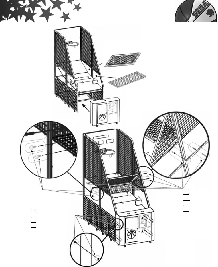
P.35 NO.31
Hexagonal Phillips screw will 2 Washers included 2 on each side
P.34 NO.08 screw (M8×16)×4
P.35 NO.19 nut (M8)×4
P.35 NO.30 washer(M10×20)×4
Ball net holder kit
Metal Shelf (optional)
Main part
P.34 NO.04 screw (M8×88)×4
P.35 NO.19 nut(M8)×4
P.35 NO.27
sleeve(φ15×43)×4
Step 8
1.Fix the 3 main cords as the following drawing.
2.Run the IC board plug and the ball holder kit plug located underneath the front
- 15 -
 Loading...