


Introduction of the Owner's Manual |
Page 1 of 1 |
[Table of Contents] [Next Page]
|
SPECIFICATIONS |
WIDTH |
62.5 in |
DEPTH |
59 in |
HEIGHT |
72 in |
WEIGHT |
Approx. 475 kg. (1200 Ibs.) |
POWER, MAXIMUM CURRENT 900W 7.5A (AC 120V 60 Hz AREA)
MONITOR |
25 INCH MEDIUM RESOLUTION |
|
COLOR MONITOR X 2 |
||
|
NOTE: Descriptions in this manual are subject to change without prior notice.
INTRODUCTION OF THE OWNER'S MANUAL
SEGA ENTERPRISES, LTD., supported by its high electronic technology of LSI's, microprocessors, etc. and a wealth of experience, has for more than 30 years been supplying various innovative and popular game machines to the world market. This Owner's Manual is intended to provide detailed descriptions together with all the necessary information covering the general operation of electronic assemblies, electromechanicals, servicing control, spare parts, etc. as regards DAYTONA USA TWIN TYPE, a new SEGA product.
This manual is intended for those who have knowledge of electricity and technical expertise especially in ICs, CRTs, microprocessors, etc. Carefully read this manual to acquire sufficient knowledge before working on the machine. Should there be a malfunction, nontechnical personnel should under no circumstances touch the interior system. Should such a case arise, contact our Main Office or the closest branch office listed as follows:
SEGA ENTERPRISES, INC. (U.S.A.) / CUSTOMER SERVICE
45133 Industrial Drive, Fremont, California 94538, U.S.A.
Phone: (650) 632-7500
Fax: (650) 632-7594
http://www.sauservice.com/manuals/Daytona%20Folder/DThtml/DT02.html |
7/8/2005 |

Daytona USA Twin Owner's Manual |
Page 1 of 2 |
|
DAYTONA USA TWIN TABLE OF CONTENTS |
|
|
Introduction of the Owner's Manual |
2 |
1. |
Handling Precautions |
3 |
2. |
Prevention of Counterfeiting and Conversion |
4 |
3. |
Precautions Concerning Installation Location |
5 |
4. |
Name of Parts |
6 |
5. |
Accessories |
7 |
6. |
Moving the Machine |
8 |
7. |
Assembling the Machine |
9 |
7-1 |
Assembling Your Daytona USA Twin Game |
9 |
7-2 |
Billboard Installation |
13 |
7-3 |
Securing to the Installation Position (Leg Adjuster Adjustment) 14 |
|
7-4 |
Power Supply and Earth Connection |
15 |
7-5 |
Turning the Power On |
15 |
7-6 |
Assembly Check |
16 |
7-7 |
How to Play |
18 |
8. |
Explanation of Test and Data Display |
20 |
8-1 |
Switch Unit |
21 |
8-2 |
Test Mode |
22 |
8-3 |
Bookeeping |
23 |
8-4 |
Game System |
25 |
8-5 |
Coin Assignment |
26 |
8-6 |
Input Test |
28 |
8-7 |
Output Test |
29 |
8-8 |
Drive DB Test |
30 |
8-9 |
Sound Test |
32 |
8-10 |
TGP Test |
33 |
8-11 |
Memory Test |
33 |
8-12 |
Backup RAM Clear |
34 |
9. |
Control Panel (Handle Mecha) |
35 |
10. |
Accelerator & Brake |
37 |
11. |
4 Speed Shifter |
38 |
12. |
Coin Selector |
41 |
13. |
Monitor Adjustments |
42 |
14. |
Replacing the Fluorescent Lamp, and Lamps |
43 |
15. |
Periodic Check |
43 |
16. |
Troubleshooting |
44 |
17. |
Game Board |
46 |
http://www.sauservice.com/manuals/Daytona%20Folder/DThtml/DT01.html |
7/8/2005 |
Daytona USA Twin Owner's Manual |
Page 2 of 2 |
18. |
Communication Play |
48 |
19. |
Design Related Parts |
52 |
20. |
Parts List |
54 |
|
ASSY BILLBOARD |
57 |
|
ASSY CONT PNL TWIN (DYN-12001) |
58 |
|
ASSY HANDLE MECHA (DYN-1250) |
60 |
|
ASSY VIRTUAL BUTTON TWIN (DYN-1290) |
63 |
|
ASSY SEAT TWIN |
64 |
|
SEAT WOOFER |
65 |
|
SPEAKER ASSEMBLY LEFT & RIGHT |
66 |
|
ASSY 4 SPEED SHIFTER (DYN1-2150) |
67 |
|
ASSY ACCEL & BRAKE (DYN-1300) |
69 |
|
ASSY BASE BOX |
71 |
21. |
Wire Color Code Table |
72 |
22. |
Wiring Diagram |
72 |
http://www.sauservice.com/manuals/Daytona%20Folder/DThtml/DT01.html |
7/8/2005 |

Accessories |
Page 1 of 1 |
[Table of Contents] [Previous Page] [Next Page]
5. ACCESSORIES
When transporting the machine, make sure that the following ports are supplied.
TABLE 5 ACCESSORIES
QTY. PART NAME
2 |
KEY |
1 |
OWNERS MANUAL DAYTONA TWIN |
1 |
500 CM OPTO CABLE |
1 |
T15 TAMPER PROOF WRENCH |
1 |
T20 TAMPER PROOF WRENCH |
1 |
T25 TAMPER PROOF WRENCH |
1 |
T27 TAMPER PROOF WRENCH |
1 |
SEAT LABELS 3-8 |
http://www.sauservice.com/manuals/Daytona%20Folder/DThtml/DT07.html |
7/8/2005 |

Name of Parts |
Page 1 of 1 |
[Table of Contents] [Previous Page] [Next Page]
4. NAME OF PARTS
http://www.sauservice.com/manuals/Daytona%20Folder/DThtml/DT06.html |
7/8/2005 |

Precautions Concerning Installation Location |
Page 1 of 1 |
[Table of Contents] [Previous Page] [Next Page]
3. PRECAUTIONS CONCERNING INSTALLATION LOCATION
The DAYTONA USA TWIN TYPE is an indoor game machine. Absolutely do not install it outside. Even indoors, avoid installing in places mentioned below so as to ensure proper usage:
{Places subject to rain or water leakage, or condensation due to humidity.
{In the proximity of an indoor swimming pool and/or shower.
{Places subject to direct sunlight.
{Places subject to heat sources from heating units, etc., or hot air.
{Vicinity of highly inflammable/volatile chemicals or hazardous matter.
{Sloped surfaces.
{Vicinity of anti-disaster facilities such as fire exits and fire extinguishers.
{Places subject to any type of violent impact.
{Dusty places.
INSTALLATION PRECAUTIONS
{1) Do not insert more than one electrical plug into the power plug socket.
2)The per unit standard voltage/amperage is 100~120V/15A.
3)Use of extension cables should be avoided. If you must use, ensure the extension cables are rated at 15A or higher for 100~120 volt areas or 10A.
4)Note that for transporting the machine into the location's building, the minimum necessary dimensions of the opening (of doors, etc.) are 36 in (W) and 80 in (H).
5)For the operation of this machine, secure a minimum area of 80 in (W) x 70 in (D).
ELECTRIC CURRENT CONSUMPTION
MAX. 7.5 A (AC 120V 60HZ)
http://www.sauservice.com/manuals/Daytona%20Folder/DThtml/DT05.html |
7/8/2005 |

Handling Precautions |
Page 1 of 1 |
[Table of Contents] [Previous Page] [Next Page]
1. HANDLING PRECAUTIONS
When installing or inspecting the machine, be very careful of the following points and pay attention to ensure that the player can enjoy the game safely.
{Be sure to turn the power off before working on the machine.
{To insert or pull out the plug quickly is dangerous.
{It is necessary to make sure that the power cord or the grounding wire is not exposed on the road, etc. in a manner so as to be dangerous. Make sure that grounding connections are made safely at the position where so specified.
{Do not use any fuse that does not meet specified rating.
{Make complete connections for the IC board and other connectors. Insufficient insertion is very dangerous.
{The operating (ambient) temperature range is from 5°C to 40°C.
{When cleaning the CRT surfaces, use a soft, dry cloth. Do not apply chemicals such as thinner, benzene, etc.
Also, for the IC board circuit inspections, only the logic tester is allowed. The use of a tester is not permitted, so be careful in this regard.
After confirming that there are no irregularities, turn the power ON.
http://www.sauservice.com/manuals/Daytona%20Folder/DThtml/DT03.html |
7/8/2005 |
Prevention of Counterfeiting and Conversion |
Page 1 of 1 |
[Table of Contents] [Previous Page] [Next Page]
2. PREVENTION OF COUNTERFEITING AND CONVERSION
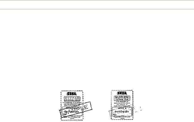
LABELING
To prevent counterfeits and conversions, the following labels are put on all SEGA products. When handling such goods, be sure to confirm the labels. They are used to prevent illegal acts such as the unauthorized copying of the products and the printed circuit boards thereof or carrying on business by manufacturing similar merchandise or by converting, selling or using such products or printed circuit boards.
ORIGINAL SEAL: The left seal is put on the machines manufactured by SEGA. LICENSE SEAL: The right seal is put on all SEGA kits, such as the printed circuit board.
COPYRIGHT NOTICE
This SEGA product has the copyright notice as follows:
(C) SEGA 1994
This signifies that this work was disclosed in 1994 and is the property of SEGA ENTERPRISES, LTD.
http://www.sauservice.com/manuals/Daytona%20Folder/DThtml/DT04.html |
7/8/2005 |

Moving the Machine |
Page 1 of 2 |
[Table of Contents] [Previous Page] [Next Page]
6. PRECAUTIONS TO BE HEEDED WHEN ASSEMBLING AND MOVING THE MACHINE
WARNING:
1.Perform the assembly work by following the procedure herein stated. Failing to comply with the instructions, for example, inserting the plug into an outlet at the stage not mentioned in this manual might cause an electric shock accident.
2.Assembling should be performed as per this manual. Since this is a complex machine, erroneous assembling may cause damage to the machine, or malfunctioning to occur.
3.When assembling, be sure to perform the work by plural persons.
When carrying out the assembly work, follow the procedure in the following sequence:
ASSEMBLING THE COCKPIT
INSTALLING THE BILLBOARD
SECURING IN PLACE (LEG ADJUSTER ADJUSTMENT)
INSTALLING THE AC COVERS (WIRING CONNECTION)
POWER SUPPLY, AND EARTH CONNECTION
TURNING THE POWER ON
ASSEMBLING CHECK
Note that the master key and the cashbox door key (accessories) in addition to the tools such as a plus screwdriver, wrench for M16 hexagon bolt and socket wrench are required for the assembly work.
CAUTION:
Perform the tightening of hexagon bolts described above after adjusting the leg adjusters. Make sure that until the leg adjuster adjustments are made, keep the hexagon bolts tightened temporarily.
http://www.sauservice.com/manuals/Daytona%20Folder/DThtml/DT08.html |
7/8/2005 |
Moving the Machine |
Page 2 of 2 |
http://www.sauservice.com/manuals/Daytona%20Folder/DThtml/DT08.html |
7/8/2005 |
Assembling Your Game |
Page 1 of 1 |
[Table of Contents] [Previous Page] [Next Page]
7. ASSEMBLING THE MACHINE
(1) ASSEMBLING YOUR DAYTONA USA TWIN GAME
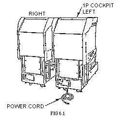
To assemble your Daytona driving game locate the Left cabinet (side with on/off switch), Cash Box Tower, and Right side cabinet.
In the parts bag located in the cash box locate the Opto cable. This will be needed later, to connect together the opto connections on the rear of Cash Box Tower. The hardware needed to assemble your Daytona driving game has game threaded into the proper holes. This was done to insure the bolts thread properly into the T nuts in the cabinet.
At this time remove the rear cover of the Cash Box Tower.
Notice the wire harness taped to the sides of the cabinets and Cash Box Tower. On the wire harness connections Black is for Left side, Yellow is for Right side viewed from front. Locate Left side cabinet (on/off switch) and Cash Box Tower. (Fig 6.1A). Connect the 15, 4, and 2 position connectors together. At this time connect the Opto cable (without white label) to the Opto connection nearest to the Left side of cabinet (viewed from front). These Opto connections are in the rear of the Cash Box Tower.
You may elect not connect the connector at this time, but carefully push the connectors in the hole so they are still accessible form the outside of the cabinet.
There are 4 bolts in NON SLOTTED holes, on the side of the cabinet, the 2 on top under the ledge must be removed. The 2 on the bottom must be loosened about a 1/4 inch. Lift up the Cash Box Tower and using the 2 lower slotted holes on the bottom of the cash box slip them over the lower protruding bolts and slide the cash box into place. Open the coin door and install the 2 upper bolts through the cash box into the cabinet. Tightened all 4 bolts.
The Right side cabinet gets installed the same way as left side (Fig. 6.1B).
Don't forget to connect all the connectors described above. The opto cables with the white labels get connected together inside the rear Cash Box Tower. The 2 remaining opto cables get connected to the 2 external opto connectors on the rear of the Cash Box Tower. This is used for linking 2 or more games (Fig. 6.1C). Replace the Cash Box Tower rear cover.
http://www.sauservice.com/manuals/Daytona%20Folder/DThtml/DT09.html |
7/8/2005 |

Assembling Your Game |
Page 1 of 1 |
[Table of Contents] [Previous Page] [Next Page]
7. ASSEMBLING THE MACHINE
(1) ASSEMBLING YOUR DAYTONA USA TWIN GAME
To assemble your Daytona driving game locate the Left cabinet (side with on/off switch), Cash Box Tower, and Right side cabinet.
In the parts bag located in the cash box locate the Opto cable. This will be needed later, to connect together the opto connections on the rear of Cash Box Tower. The hardware needed to assemble your Daytona driving game has game threaded into the proper holes. This was done to insure the bolts thread properly into the T nuts in the cabinet.
At this time remove the rear cover of the Cash Box Tower.
Notice the wire harness taped to the sides of the cabinets and Cash Box Tower. On the wire harness connections Black is for Left side, Yellow is for Right side viewed from front. Locate Left side cabinet (on/off switch) and Cash Box Tower. (Fig 6.1A). Connect the 15, 4, and 2 position connectors together. At this time connect the Opto cable (without white label) to the Opto connection nearest to the Left side of cabinet (viewed from front). These Opto connections are in the rear of the Cash Box Tower.
You may elect not connect the connector at this time, but carefully push the connectors in the hole so they are still accessible form the outside of the cabinet.
There are 4 bolts in NON SLOTTED holes, on the side of the cabinet, the 2 on top under the ledge must be removed. The 2 on the bottom must be loosened about a 1/4 inch. Lift up the Cash Box Tower and using the 2 lower slotted holes on the bottom of the cash box slip them over the lower protruding bolts and slide the cash box into place. Open the coin door and install the 2 upper bolts through the cash box into the cabinet. Tightened all 4 bolts.
The Right side cabinet gets installed the same way as left side (Fig. 6.1B).
Don't forget to connect all the connectors described above. The opto cables with the white labels get connected together inside the rear Cash Box Tower. The 2 remaining opto cables get connected to the 2 external opto connectors on the rear of the Cash Box Tower. This is used for linking 2 or more games (Fig. 6.1C). Replace the Cash Box Tower rear cover.
http://www.sauservice.com/manuals/Daytona%20Folder/DThtml/DT09.html |
7/8/2005 |

Billboard Installation |
Page 1 of 2 |
[Table of Contents] [Previous Page] [Next Page]
BILLBOARD INSTALLATION
1.Remove billboard form carton and remove upper holder and billboard plate. Remove billboard holders and hardware package from inside billboard case.
Remove (8) 5/16 in hex bolts from top of cabinet.
2.Attach billboard holders to rear of billboard case thru vertical slots with (4) 5/16 - 18 x 1" lg hex bolts and flat washers, lightly tighten.
3.Mount billboard case across top of both cabinets and attach with (4) 5/16 - 18 x 1" lg hex bolts and flat washers thru mtg. holes. Do not tighten.
4.Loosen billboard holders on rear of case and align over mtg. holes. Secure with (4) 5/16 -18 x 1" lg hex bolts and flat washers.
5.Align billboard case and tighten all mtg. bolts.
6.Connect the (3) billboard connectors. Two (blue & white) connectors on left side, 9 (blue) on right side. There is a extra white connector on Right side that is not used.
7.Replace billboard plate and upper holder.
http://www.sauservice.com/manuals/Daytona%20Folder/DThtml/DT13.html |
7/8/2005 |

Billboard Installation |
Page 2 of 2 |
http://www.sauservice.com/manuals/Daytona%20Folder/DThtml/DT13.html |
7/8/2005 |

Leg Adjuster Adjustment |
Page 1 of 2 |
[Table of Contents] [Previous Page] [Next Page]
(3) SECURING TO THE INSTALLATION POSITION (LEG ADJUSTER ADJUSTMENT)
WARNING!
Make sure that all of the leg adjusters are in contact with the floor. If they are not, the cabinet may move and cause an accident to occur.
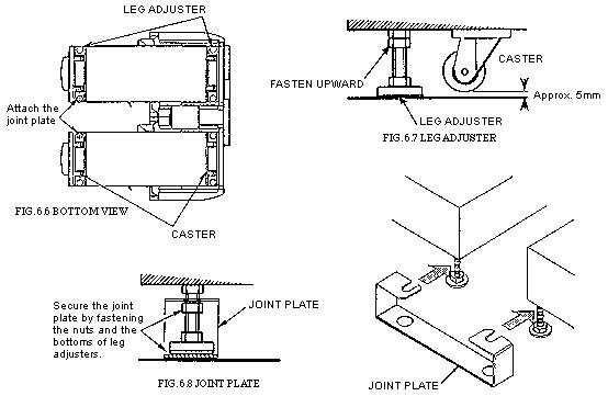
This machine has eight casters and eight leg adjusters (Fig 6.6). When the installation position is determined, cause the leg adjusters to come into contact with the floor directly, make adjustments in a manner so that the casters will be raised approximately 5 mm. from the floor and make sure that the machine position is level.
1.Move the machine to the installation position. When installing the machine against or close to a wall, be sure to secure a passage space to enable the player to take a ride in the machine.
2.Attach the joint plate for the 2 internal leg adjusters shown. First, cause the other 6 leg adjusters to come into contact with the floor. Make leg adjuster adjustments with a wrench in a manner to ensure the machine's position is level (Fig. 6.6).
3.After making adjustments, fasten the leg adjuster nut upward and secure the height of the leg adjuster (Fig. 6.7).
4.Insert the notch portions of the joint plate to the 2 leg adjusters.
5.Lower the leg adjuster and fasten the nut upward. Secure the joint plate with the nuts and the bottoms of the leg adjuster (Fig. 6.8).
http://www.sauservice.com/manuals/Daytona%20Folder/DThtml/DT14.html |
7/8/2005 |
Leg Adjuster Adjustment |
Page 2 of 2 |
http://www.sauservice.com/manuals/Daytona%20Folder/DThtml/DT14.html |
7/8/2005 |
Power, Earth & Power On |
Page 1 of 2 |
[Table of Contents] [Previous Page] [Next Page]
(4) POWER SUPPLY AND EARTH CONNECTION
The AC UNIT is located on the back of the 1P cockpit (cabinet).
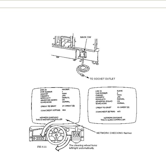
(5) TURNING THE POWER ON
Turning the AC UNIT's MAIN SW on will cause the machine to start the POWER ON check and NETWORK check automatically.
In the POWER ON check, the steering wheel turns left and right, then returns to the centering position and stops. In this check, the values of V.R. inside the control panel are corrected. Until the check is finished (the steering wheel stops automatically), do not touch the steering wheel or play the game.
If you do, the steering wheel reaction during the game (reaction at the time of a course-out or crashing) can not be obtained correctly.
In a case of a strange reaction during the game, turn the power on again from the beginning and complete the power-on check.
http://www.sauservice.com/manuals/Daytona%20Folder/DThtml/DT15.html |
7/8/2005 |
Power, Earth & Power On |
Page 2 of 2 |
During network checking, "NETWORK CHECKING" flashes on the screen. At this time, current settings are displayed on the screen. When NETWORK CHECKING is finished, the DEMO mode will appear on the monitor screen.
http://www.sauservice.com/manuals/Daytona%20Folder/DThtml/DT15.html |
7/8/2005 |
Assembly Check |
Page 1 of 1 |
[Table of Contents] [Previous Page] [Next Page]
(6) ASSEMBLY CHECK
In the TEST MODE, ascertain that the assembly has been made correctly and IC BD., is satisfactory (refer to Section 8).
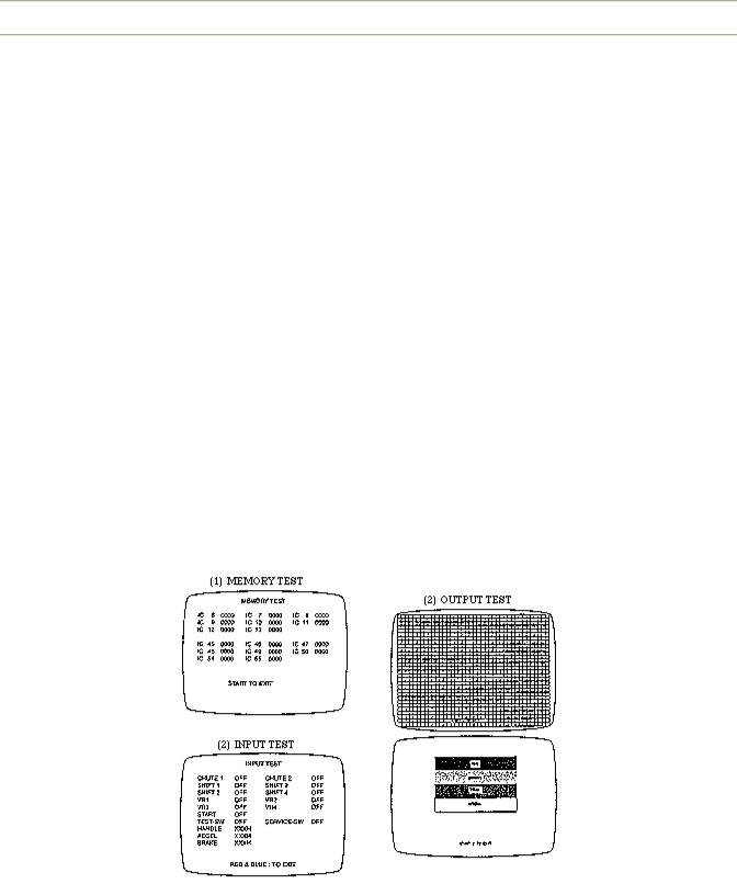
In the test mode, perform the following test:
Selecting the MEMORY TEST on the test mode menu screen causes the on-board memory to be tested automatically. The game board is satisfactory if the display beside each IC No. shows GOOD.
Selecting the INPUT TEST on the test mode menu screen causes the screen (on which each switch and V.R. are tested) to be displayed. Press each switch. For the coin switch test, insert a coin from the coin inlet with the coin chute door being open. If the display beside each switch indicates "ON", the switch and wiring connections are satisfactory.
Ascertain the display of V.R. value for the steering wheel and accelerator & brake. If the V.R. values are not satisfactory, refer to Sections 9 & 10.
In the TEST mode menu, selecting OUTPUT TEST allows the screen (on which the monitor is tested) to be displayed. Although the monitor adjustments have been made at the time of shipment from the factory, make judgment (by watching the test mode screen) as to whether an adjustment is needed. If it is necessary, adjust the monitor by referring to Section 13.
http://www.sauservice.com/manuals/Daytona%20Folder/DThtml/DT16.html |
7/8/2005 |
 Loading...