


TABLE OF CONTENTS
BEFORE USING THE PRODUCT, BE SURE TO READ THE FOLLOWING: TABLE OF CONTENTS
INTRODUCTION
1 HANDLING PRECAUTIONS••••••••••••••••••••••••••••••••••••••••••••••••••1
2 PRECAUTIONS REGARDING INSTALLATION LOCATION••••••••••••••••4
2-1 LIMITATIONS OF USAGE ••••••••••••••••••••••••••••••••••••••••••••••••••••••••••••••••••••••••••••••••••••••4
2-2 OPERATION AREA••••••••••••••••••••••••••••••••••••••••••••••••••••••••••••••••••••••••••••••••••••••••••••••••5
3 PRECAUTIONS REGARDING PRODUCT OPERATION •••••••••••••••••••6
3-1 BEFORE OPERATION••••••••••••••••••••••••••••••••••••••••••••••••••••••••••••••••••••••••••••••••••••••••••••6
3-2 DURING OPERATION (PAYING ATTENTION TO CUSTOMERS) •••••••••••••••••••••••••••••7
4 PART DESCRIPTIONS••••••••••••••••••••••••••••••••••••••••••••••••••••••••8
5 ACCESSORIES••••••••••••••••••••••••••••••••••••••••••••••••••••••••••••••••9
6 INSTALLATION•••••••••••••••••••••••••••••••••••••••••••••••••••••••••••••••11
6-1 SECURE THE UNIT AT THE INSTALLATION SITE
(MANIPULATE THE ADJUSTERS)••••••••••••••••••••••••••••••••••••••••••••••12 6-2 REMOVE SHIPPING BRACKETS •••••••••••••••••••••••••••••••••••••••••••••••••••••••••••••••••••••••••13 6-3 ATTACH PARTITION•••••••••••••••••••••••••••••••••••••••••••••••••••••••••••••••••••••••••••••••••••••••••••••15 6-4 CONNECT POWER CORD •••••••••••••••••••••••••••••••••••••••••••••••••••••••••••••••••••••••••••••••••••16 6-5 ACTIVATE POWER SUPPLY ••••••••••••••••••••••••••••••••••••••••••••••••••••••••••••••••••••••••••••••••17
7 PRECAUTIONS WHEN MOVING •••••••••••••••••••••••••••••••••••••••••••18
8 PRIZE REPLACEMENT •••••••••••••••••••••••••••••••••••••••••••••••••••••19
9 GAME CONTENT ••••••••••••••••••••••••••••••••••••••••••••••••••••••••••••21
10GAME BOARD •••••••••••••••••••••••••••••••••••••••••••••••••••••••••••••••23
11EXPLANATION OF TEST AND DATA DISPLAY•••••••••••••••••••••••••••25
11-1 SWITCH UNIT AND CASH BOX••••••••••••••••••••••••••••••••••••••••••••••••••••••••••••••••••••••••••25 11-2 VFD DISPLAY CONTENT •••••••••••••••••••••••••••••••••••••••••••••••••••••••••••••••••••••••••••••••••••26 11-3 EXPLANATION OF TEST MODE•••••••••••••••••••••••••••••••••••••••••••••••••••••••••••••••••••••••••31
12 DIP SW SETTINGS ••••••••••••••••••••••••••••••••••••••••••••••••••••••••••33
E1-0605 |
420-6953 |
1
2
3
4
5
6
7
8
9
10
11
12
13
14
15
16
17
18
19
20
21
22
23
24
i

1
13 ARM MECHANISM ••••••••••••••••••••••••••••••••••••••••••••••••••••••••••37
213-1 ARM REPLACEMENT ••••••••••••••••••••••••••••••••••••••••••••••••••••••••••••••••••••••••••••••••••••••••37
313-2 ADJUSTMENT OF SENSOR BRACKET POSITION•••••••••••••••••••••••••••••••••••••••••••••40
13-3 SPRING STRENGTH ADJUSTMENT AND SPRING REPLACEMENT•••••••••••••••••••43
413-4 SHOVEL REPLACEMENT AND ADJUSTMENT ••••••••••••••••••••••••••••••••••••••••••••••••••45
13-5 OPEN ARM ANGLE ADJUSTMENT ••••••••••••••••••••••••••••••••••••••••••••••••••••••••••••••••••••46
5
14 MAINTENANCE OF Z-ORIENTED MECHANISM••••••••••••••••••••••••••47
6
15 |
COIN SELECTOR ••••••••••••••••••••••••••••••••••••••••••••••••••••••••••••49 |
7 |
15-1 REMOVING THE COIN SELECTOR ••••••••••••••••••••••••••••••••••••••••••••••••••••••••••••••••••••49 |
15-2 REMOVING A JAMMED COIN ••••••••••••••••••••••••••••••••••••••••••••••••••••••••••••••••••••••••••••50
815-3 CLEANING THE COIN SELECTOR•••••••••••••••••••••••••••••••••••••••••••••••••••••••••••••••••••••51
15-4 COIN INSERTION TEST •••••••••••••••••••••••••••••••••••••••••••••••••••••••••••••••••••••••••••••••••••••51
9
10 |
16 REPLACEMENT OF FLUORESCENT LIGHTING, LAMPS, AND FUSES••••••••52 |
|
16-1 FLUORESCENT LIGHTING REPLACEMENT ••••••••••••••••••••••••••••••••••••••••••••••••••••••52 |
1116-2 LAMP REPLACEMENT•••••••••••••••••••••••••••••••••••••••••••••••••••••••••••••••••••••••••••••••••••••••53
16-3 FUSE REPLACEMENT •••••••••••••••••••••••••••••••••••••••••••••••••••••••••••••••••••••••••••••••••••••••56
12
17 PERIODIC INSPECTION ••••••••••••••••••••••••••••••••••••••••••••••••••••57
13
18 ERROR MESSAGES•••••••••••••••••••••••••••••••••••••••••••••••••••••••••58
14
19 TROUBLESHOOTING •••••••••••••••••••••••••••••••••••••••••••••••••••••••59
15
1620 DESIGN-RELATED PARTS••••••••••••••••••••••••••••••••••••••••••••••••••60
1721 OPTIONAL ITEMS••••••••••••••••••••••••••••••••••••••••••••••••••••••••••••61
|
21-1 DOLLAR BILL VALIDATOR ••••••••••••••••••••••••••••••••••••••••••••••••••••••••••••••••••••••••••••••••61 |
18 |
21-2 SECURITY BAR •••••••••••••••••••••••••••••••••••••••••••••••••••••••••••••••••••••••••••••••••••••••••••••••••63 |
|
21-3 LCD UNIT (LCD CASE + CABLE COVER)•••••••••••••••••••••••••••••••••••••••••••••••••••••••••••67 |
19
20 |
22 PARTS LIST ••••••••••••••••••••••••••••••••••••••••••••••••••••••••••••••••••75 |
|
|
21 |
23 WIRE COLOR CODE TABLE•••••••••••••••••••••••••••••••••••••••••••••••114 |
|
|
22 |
24 WIRING DIAGRAM •••••••••••••••••••••••••••••••••••••••••••••••••••••••••115 |
|
|
23 |
|
24 |
|
ii

INTRODUCTION
This manual is intended to provide detailed descriptions together with all the necessary information covering the general operation of electronic assemblies, electro-mechanicals, servicing control, spare parts, etc. for the product,
"SEGA UFO CATCHER".
This manual is intended for the owners, personnel and managers in charge of operation of the product. Operate the product after carefully reading and sufficiently understanding the instructions.
In the unlikely event that the product does not function correctly, DO NOT allow anyone other than a technician to touch the internal system. Turn off the power to the machine, making sure to unplug the electrical cord from the outlet, and contact the office listed below or the point-of-purchase for this product.
Use of this product is unlikely to cause physical injuries or damage to property. However, points that require special attention are indicated by thick underlining, the word "IMPORTANT" and the symbol below
IMPORTANT
Indicates important information that, if ignored, may result in the mishandling of the product and cause faulty operation or damage to the product.
Sega Amusements U.S.A., Inc.
800ArthurAvenue, Elk Grove Village, IL 60007-5215, U.S.A.
TEL: |
1-847-364-9787 |
TOLL FREE: |
1-888-877-2669 |
FAX: |
1-847-427-1065 |
|
SPECIFICATIONS |
Installation space: |
1,683 mm (66.3 in) [Width] x 875 mm (34.4 in) [Depth] |
|
<Full options assembled: 989 mm (38.9 in) [Depth]> |
Height: |
1,972 mm (77.6 in) |
Weight: |
295 kg (650.4 lb) |
Power, maximum current: |
267 W, 2.4A(AC 120 V, 60 Hz) |
INTRODUCTION
iii

INTRODUCTION
Definition of 'Site Maintenance Personnel or Other Qualified Individuals'
Procedures not described in this manual or marked as ‘to be carried out by site maintenance personnel or other qualified professionals’ should not be carried out by personnel without the necessary skill or technology. Work carried out by unqualified persons may cause serious accidents, including electrocution.
Parts replacement, maintenance inspections and troubleshooting should be carried out by site maintenance personnel or other qualified professionals. This manual includes directions for potentially dangerous procedures which should only be carried out by professionals with the appropriate specialized knowledge.
The site maintenance personnel or other qualified professionals mentioned in this manual are defined as follows:
Site maintenance personnel:
Individuals with experience in maintaining amusement equipment, vending machines, etc., working under the supervision of the owner/operator of this product to maintain machines within amusement facilities or similar premises by carrying out everyday procedures such as assembly, maintenance inspections, and replacement of units/expendable parts.
Activities to be carried out by site maintenance personnel:
Amusement equipment/vending machine assembly, maintenance inspection and replacement of units/expendable parts.
Other qualified professionals:
Persons employed by amusement equipment manufacturers, or involved in design, production, testing or maintenance of amusement equipment. The individual should have either graduated from technical school or hold similar qualifications in electrical/electronics/mechanical engineering.
Activities to be carried out by other qualified professionals:
Amusement equipment/vending machine assembly, repair/adjustment of electrical/electronic/mechanical parts.
iv

1 HANDLING PRECAUTIONS
When installing or inspecting the machine, be very careful of the following points and pay attention to ensure that the player can enjoy the game safely.
Non-compliance with the following points or inappropriate handling running counter to the cautionary matters herein stated can cause personal injury or damage to the machine.
•Before performing work, be sure to turn the power off and unplug the electrical cord from the outlet. Performing the work without turning the power off can cause an electric shock or short circuit. In the case work should be performed in the status of power on, this manual always states to that effect.
•To avoid an electric shock or short circuit, do not plug in or unplug quickly.
•To avoid an electric shock, do not plug in or unplug with a wet hand.
•Do not expose power cords or earth wires on the surface, (floor, passage, etc.). If exposed, the power cords and earth wires are susceptible to damage. Damaged cords and wires can cause an electric shock or short circuit.
•To avoid causing a fire or an electric shock, do not put things on or damage the power cords.
•When or after installing the product, do not unnecessarily pull the power cord. If damaged, the power cord can cause a fire or an electric shock.
•In case the power cord is damaged, ask for a replacement through where the product was purchased from or the office herein stated. Using the cord as is damaged can cause fire, an electric shock or leakage.
•Be sure to perform grounding appropriately. Inappropriate grounding can cause an electric shock.
•Be sure to use fuses meeting the specified rating. Using fuses exceeding the specified rating can cause a fire or an electric shock.
•Completely make connector connections for IC BD and others. Insufficient insertion can cause an electric shock.
•Specification changes, removal of equipment, conversion and/or addition, not designated by SEGA are not permitted.
-Failure to observe this may cause a fire or an electric shock. Non-compliance with this instruction can have a bad influence upon physical conditions of the players or the onlookers, or result in injury during play.
-SEGA shall not be held responsible for damage, compensation for damage to a third party, caused by specification changes not designated by SEGA.
•Be sure to perform periodic maintenance inspections herein stated.
1 HANDLINGPRECAUTIONSAS
1

1 HANDLINGPRECAUTIONSAS
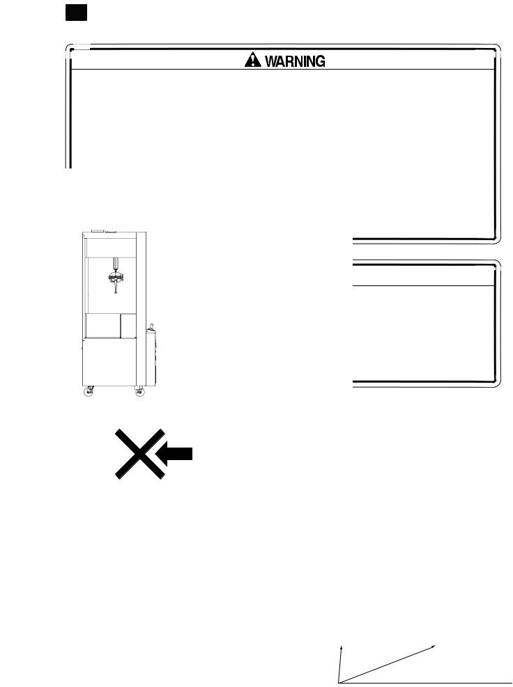
•This game machine can be installed at a storefront but could tip over due to sudden strong drafts or building winds. It could also tip over from man-made loads. If the game machine does fall down, a serious accident could result. To prevent the machine from falling down, carry out the following procedures and make every effort to operate the machine safely.
-Never place the product at a site that is inclined or has level differences. If there are inclines or level differences, make sure the site is level before placing the machine on it.
-Do not add decorations to the product that will cause its center of gravity to be elevated. Also, be aware that there are cases in which it is illegal to add electrical units to the product interior.
-Make sure that the adjusters are always in contact with the floor.
-Use rope, chain, and/or fixtures for securing furniture to secure the product so that it will not fall down in an earthquake.
IMPORTANT
•For the IC board circuit inspections, only the logic tester is allowed. The use of a multiple-purpose tester is not permitted, so be careful in this regard.
•Static electricity from your body may damage some electronics devices on the IC board. Before handling the IC board, touch a grounded metallic surface so that the static electricity can be discharged.
•Some parts are the ones designed and manufactured not specifically for this game machine. The manufacturers may discontinue, or change the specifications of, such general-purpose parts. If this is the case, Sega cannot
repair or replace a failed game machine whether or not a warranty period has expired.
2

CONCERNING THE STICKER DISPLAY |
|
CONCERNING WARNING DISPLAYS |
This SEGAproduct has stickers attached describing the product manufacture No. (Serial No.) and Electrical Specifications. When inquiring about or asking for repairs, mention the Serial No. and Name of Machine indicated on the Sticker. The Serial Number indicates the product register. Identical machines could have
different parts depending on the date of production.Also, improvements and modifications might have been made after the publication of this manual. In order to ensure you order the correct parts, mention the Serial No. when contacting the applicable places.
This SEGAproduct has warning displays on stickers, labels and/or printed instructions adhered/attached to or incorporated in the places where a potentially hazardous situation could arise. The warning displays are intended for accident prevention for customers and for avoiding hazardous situations relating to maintenance and servicing work. Some portions of the cabinet contain high voltage and may cause accidents if touched. When performing maintenance, be very careful of the warning displays. It is especially important that any complex repair and replacement work not mentioned herein should be performed by those technical personnel who have knowledge of electricity and technical expertise.
In order to prevent accidents, caution any customer ignoring the warnings to cease and desist immediately.
Same on 2P side
440-CS0245-EG
440-CS0245-EG
440-WS0027-EG
440-WS0002XEG
440-CS0316-EG |
SERIAL NO. DISPLAY |
|
|
|
UL CERTIFICATION DISPLAY |
|
FIG. 1 |
1 HANDLINGPRECAUTIONSAS
3
2
REGARDING PRECAUTIONS LOCATION INSTALLATION
2 PRECAUTIONS REGARDING INSTALLATION LOCATION
This product is an indoor game machine. Do not install it outside. Even indoors, avoid installing in places mentioned below so as not to cause a fire, electric shock, injury and/or malfunction.
-Places subject to rain or water leakage, or places subject to high humidity in the proximity of an indoor swimming pool and or shower, etc.
-Places subject to direct sunlight, or places subject to high temperatures in the proximity of heating units, etc.
-Places filled with inflammable gas or vicinity of highly inflammable/volatile chemicals or hazardous matter.
-Dusty places.
-Sloped surfaces.
-Places subject to any type of violent impact.
-Vicinity of anti-disaster facilities such as fire exits and fire extinguishers.
-The operating (ambient) temperature range is from 5°C to 35°C (5°C to 30°C with LCD).
 2-1 LIMITATIONS OF USAGE
•Be sure to check the Electrical Specifications. Ensure that this product is compatible with the location’s power supply, voltage and frequency
requirements. A plate describing Electrical Specifications is attached to the product. Non-compliance with the Electrical Specifications can cause a fire and electric shock.
•This product requires a breaker and earth mechanism as part of the location facilities. Using the product without these can cause a fire and electric shock.
•Ensure that the indoor wiring for the power supply is rated at 7A or higher. Noncompliance with the Electrical Specifications can cause a fire and electric shock.
•Be sure to use an independent power supply equipped with an earth leakage breaker. Using a power supply without an earth leakage breaker can cause an outbreak of fire if a power surge occurs.
•Putting many loads on one electrical outlet can cause generation of heat and a fire resulting from overload.
•When using an extension cord, ensure that the cord is rated at 7A or higher. Using a cord rated lower than the specified rating can cause a fire and electric shock.
4

 2-2 OPERATION AREA
•For the operation of this machine, secure a minimum area of 1.7 m (66.9 in) [W] x 1.6 m (60.0 in) [D]. <Full options assembled: 1.7 m (66.9 in) [W] x 1.8 m (70.9 in) [D]>
•Do not block the ventilation port on the top surface. Heat may build up and cause a fire.
•SEGA shall not be held responsible for damage or compensation for damage to a third party, resulting from the failure to observe this instruction.
IMPORTANT
In order to transport the machine into a building, the minimum necessary dimensions of the opening (of doors, etc.) are 0.9 m (35.4 in) [W] and 2 m (78.7 in) [H].
Electricity Consumption:
MAX. 2.4A(AC 120 V, 60 Hz)
Ventilation port |
Ventilation port |
|
|
|
0.1m (3.9in) |
|
1.8m (70.9in) |
|
|
1.6m (60.0in) |
|
|
|
||
|
||||||
|
|
|
1.7m (66.9in) |
|
|
|
1.7m (66.9in) |
|
|
|
|||
2m (78.7in) |
|
2m (78.7in) |
|
||
|
|
|
|
|
|
|
|
|
|
|
|
|
|
|
|
|
|
FIG. 2-2a Basic Cabinet |
FIG. 2-2b Full Options Cabinet (See Section 21.) |
2
REGARDING PRECAUTIONS LOCATION INSTALLATION
5
3
REGARDING PRECAUTIONS OPERATION PRODUCT
3 PRECAUTIONS REGARDING PRODUCT OPERATION
 3-1 BEFORE OPERATION
To avoid injury and trouble, be sure to pay attention to the behavior of visitors and players.
In order to avoid accidents, check the following before starting the operation:
FIG. 3-1
Ensure that all the adjusters are in contact with the floor.
•Check if all of the adjusters are in contact with the surface. If they are not, the cabinet can move and cause an accident.
•Do not place items over the ventilation port on the top surface. Heat may build up and cause a fire.
•Do not put any heavy items on this product. Placing heavy items on the product can cause accidents or damage to parts.
•Do not climb on the product. Climbing on the product can cause accidents. To check the top portion of the product, use a stepladder.
•To avoid electric shock, check that none of the door & cover parts are damaged or missing.
•To avoid electric shock, short circuit and or parts damage, do not put the following items on or in the periphery of the product. Flower vases, flowerpots, cups, water tanks, cosmetics, and receptacles/containers/vessels containing chemicals or water.
To avoid injury, be sure to provide sufficient space by considering the crowd situation at the installation location. Insufficient installation space can cause customers to bump into each other, causing trouble.
6
 3-2 DURING OPERATION (PAYING ATTENTION TO CUSTOMERS)
To avoid injury and trouble, be sure to pay attention to the behavior of visitors and players.
•To avoid injury from falls and electric shocks due to spilled drinks, instruct the player not to place heavy items or drinks on the product.
•To avoid electric shocks and short circuits, do not allow customers to put hands and fingers or extraneous matter in the openings of the product or small openings in or around the doors.
•To avoid falls and resulting injury, immediately stop the customer from leaning against or climbing on the product, etc.
•To avoid electric shocks and short circuits, do not allow customers to unplug the power plug without a justifiable reason.
•If hands or fingers are placed deeper than necessary into the prize retrieval slot or coin return slot, they could get caught, resulting in injury. Caution is required, especially for small children.
•Immediately stop such violent acts as hitting and kicking the product. Such violent acts can cause parts damage or cause the cabinet to fall over, resulting in injury.
3
REGARDING PRECAUTIONS OPERATION PRODUCT
7
4 PART DESCRIPTIONS
UFO MECHANISM
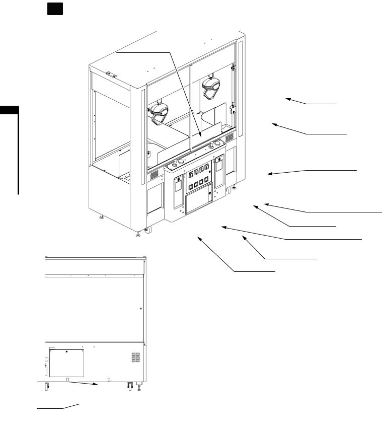
4 PARTDESCRIPTIONS
BACK LID
AC UNIT 
NOTE: For optional items, see Section 21.
CABINET
GLASS DOOR
CONTROL PANEL
LEFT SIDE: 1P
RIGHT SIDE: 2P
BILL VALIDATOR DOOR 2P
SERVICE DOOR
BILL VALIDATOR DOOR 1P
CASH BOX DOOR
PRIZE DOOR
8

5 ACCESSORIES
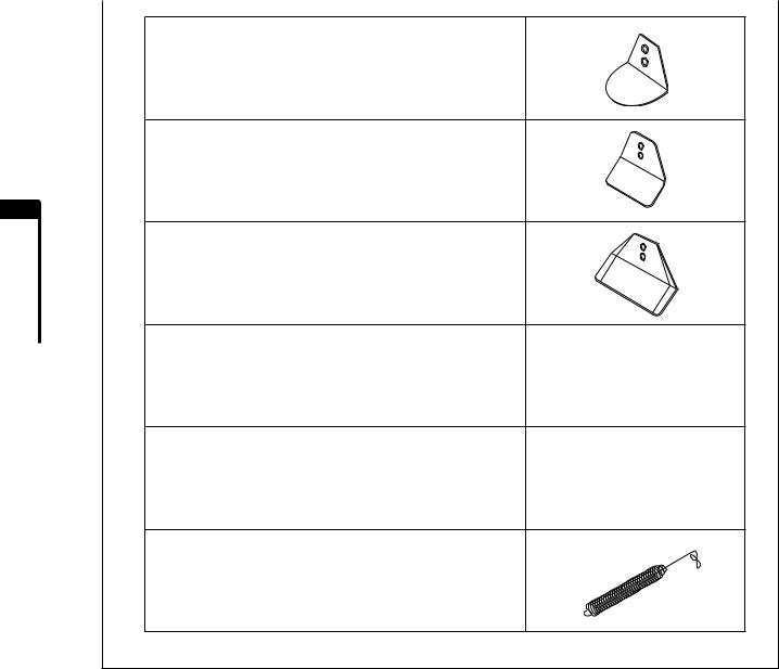
Confirm that the accessories listed in the table below are present when setting up the product. Accessories marked "Spare" in the usage note column are consumable items but included as spares.
TABLE 5 ACCESSORIES
DESCRIPTION: |
OWNER’S MANUAL |
Part No. (Qty.): |
420-6953 (1) |
Usage notes & Diagram: |
This manual |
Parts not labeled with part numbers are as yet unregistered or cannot be registered. Be sure to handle all parts with care, as some parts are not available for purchase separately.
OPERATOR’S KEY
220-5793-2-A002 (4)
For opening/closing the glass door and service door
MASTER KEY 220-5793-2-A001 (2)
For opening/closing the back lid
KEYS (3 TYPES) (2 of each)
- For cash box door
-For bill validator door 1P (left)
-For bill validator door 2P (right)
TRUSS SCREW (CHROME) 000-T00408-0C (2)
For installation, see Section 6 [2]
POWER CORD 600-7326 (1)
For installation, see Section 6 [6]
TAMPERPROOF WRENCH M4 540-0006-01 (1)
Tool
NOTE: The wrench shown in the figure is provided as an accessory tool but a driver type tool, the 540-0018 (DRIVER TAMPER M4), is also available. If you wish to purchase it, contact the office indicated on these instructions or where the product was purchased.
5 ACCESSORIES
9
|
SHOVELW30 |
|
EG-3405Y (4) |
|
For replacement, see Section 12-4 |
|
SHOVELW40 |
|
MKW-2120 (4) |
|
For replacement, see Section 12-4 |
5 |
|
ACCESSORIES |
SHOVELW60 |
EG-3404 (4) |
|
For replacement, see Section 12-4 |
|
|
|
|
ARM S |
|
UCS-3430 (4) |
|
For replacement, see Section 13 |
|
ARM L |
|
UCS-3432 (4) |
|
For replacement, see Section 13 |
|
SLIDE SPRING |
|
USS-3418 (2) |
|
Spare, see Section 13 |
10

6 INSTALLATION
To install the unit, follow these instructions in this manual carefully. If the unit is not installed properly, it may cause personal injury or damage to the machine.
Carry out the following five steps to assemble and install the product.
 6-1 SECURE THE UNIT AT THE INSTALLATION SITE (MANIPULATE THE ADJUSTERS)
 6-2 REMOVE SHIPPING BRACKETS
 6-3 ATTACH PARTITION
 6-4 CONNECT POWER CORD
 6-5 ACTIVATE POWER SUPPLY
For assembly and installation, you need a Philips screwdriver, adjustable wrench (for 24mm hexagonal bolts) and the operator’s key.
OPERATOR’S KEY
PHILIPS SCREWDRIVER (For M4 screws)
WRENCH (for M16 HEXAGONAL BOLTS)
24 mm
6 INSTALLATION
11

6 INSTALLATION
 6-1 SECURE THE UNITAT THE INSTALLATION SITE (MANIPULATE THEADJUSTERS)
Make sure that all the adjusters are in contact with the floor. Otherwise the cabinet may move, causing an accident.
The product comes with 4 casters and 4 adjusters (Figure 6-1a).After the installation site has been determined, have the adjusters come directly in contact with the floor, establish a gap of about 5 mm between the casters and the floor surface, and adjust the adjusters so that the game machine is level.
1.Move the product to the installation site.
2.Adjust the adjusters so that they come in contact with the floor. Use the wrench to adjust the heights of the adjusters so that the game machine is level.
3.After making adjustments, tighten the adjuster nut upwards so that the adjuster height is fixed.
ADJUSTER
Tighten nut upwards.
ADJUSTER (4)
FIG. 6-1a Bottom View
CASETER
Approximately 5mm
ADJUSTER
FIG. 6-1b Adjuster in contact with floor
A1:100 scale view of the unit. Use it as a reference for installation site layout.
FIG. 6-1c Basic Cabinet |
FIG. 6-1d Full Options Cabinet |
|
(See Section 21.) |
12
 6-2 REMOVE SHIPPING BRACKETS
•Hold the parts to be removed firmly and then remove the screws that hold them in place. If parts are not held firmly, they may fall and cause an accident.
•Do not move the UFO mechanism while holding onto parts not described in the procedures. You may get your fingers, etc., caught and be injured.
IMPORTANT
•The mechanism is secured in place for shipment so it will not be damaged during transport. Before activating the power supply, be sure to remove the shipping brackets used to secure the mechanism. If they are not removed, parts may get damaged.
•Shipping brackets are required for preventing damage during transport. Be sure to store them carefully.
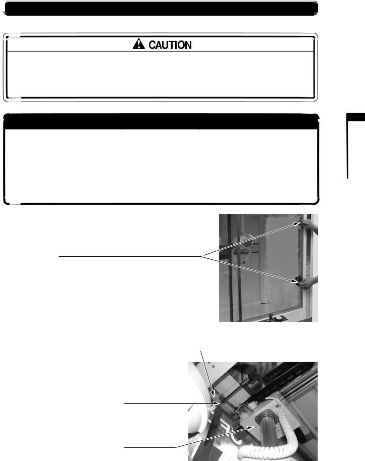
1.Open the glass door with the operator’s key.
Unlock and open glass door.
(The opposite side can be opened in similar fashion)
|
PHOTO 6-2a |
2. Remove the screw in the shipping bracket mechanism. |
SHIPPING BRACKET MECHANISM |
SCREW (1)
M4 x 8, with flat & spring washers
Z MECHANISM
PHOTO 6-2b
6 INSTALLATION
13
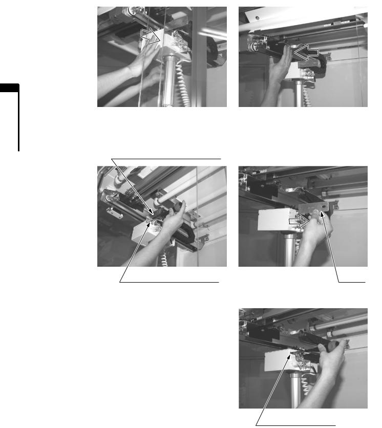
3.Move the UFO mechanism to a location where it will be easy to work. Place hand as shown in the photo and move the mechanism. Do not move holding other parts as you may get your fingers caught and be injured.Also, the mechanism itself may become damaged.
6 INSTALLATION
PHOTO 6-2c
4.Remove the screw. Make sure to hold the shipping bracket mechanism so it will not fall down, then remove the screw.
SHIPPING BRACKET MECHANISM
SCREW (1) |
PHOTO 6-2d |
Remove |
|
M4 x 8, with flat & spring washers
5.Secure in place with the accessory truss screw.
6.Perform steps 3, 4, and 5 again on the opposite side.
TRUSS SCREW (1), chrome
M4 x 8
PHOTO 6-2e
14
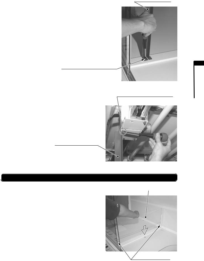
7.Remove the two screws at the bottom of the shipping center bar.
SCREW (2)
M4 x 8, with flat & spring washers
8.Remove the screw at the top of the shipping center bar.
Make sure to hold the shipping center bar, then remove the screw.
SHIPPING CENTER BAR
 6-3 ATTACH PARTITION
When attaching the partition, insert the partition CL into the partition bracket CL.
SHIPPING CENTER BAR
PHOTO 6-2f
SCREW (1)
M4 x 8, with flat & spring washers
PHOTO 6-2g
PARTITION CL
PARTION BRACKET CL
PHOTO 6-3
6 INSTALLATION
15
6 INSTALLATION
 6-4 CONNECT POWER CORD
•Use a power supply equipped with an electric leakage circuit breaker. If you use a power supply without an electric leakage circuit breaker, a short circuit may occur and start a fire.
•After laying out the power cord on the floor, make sure that it is securely protected from exposure. If the cord is exposed anywhere, it could easily be damaged if a customer should trip or stumble over it. Such damages could cause accidents from electrical shocks or short circuits. Either lay out the cord so it will not interfere with customer traffic, or protect it with a cover.
1.There is anAC unit on the cabinet rear panel. TheAC unit has a main switch and an inlet for connecting the power cord.
INLET |
CIRCUIT PROTECTOR |
|
|
2. Confirm that the main switch is OFF.
To power outlet |
|
MAIN SWITCH OFF |
|
|
|
|
FIG. 6-4a AC Unit |
MAIN SWITCH |
|
|
3.The power cord is inserted from the bottom of the cabinet and comes out through a hole in theAC unit. However, it is not absolutely necessary to pass the cord through the hole. In some cases, depending on the environment in which the unit will be used, you can connect the power cord directly into the inlet.
4.Insert the power cord connector into the inlet securely.
5.Insert the power cord plug into the power outlet securely.
6.Lay out the power cord. Place a cover over the laid out power cord so that it will be protected.
PHOTO 6-4
POWER CORD COVER
FIG. 6-4b Power Card Layout
16
 6-5 ACTIVATE POWER SUPPLY
On this product, there is a power supply switch on theAC unit on the cabinet rear panel and on the internal switch unit. (The internal switch unit is inside the service door. Use the operator’s key to open the service door.)
Even when both of these switches are ON, there will be no power unless the glass doors on right and left are closed securely. Normally, leave one of these switches ON and turn the other power supply switch ON/OFF to use. When the power supply is activated, the billboard, the internal fluorescent lighting, and the left and right fluorescent lights all turn on.
Now we will check the operation (initialization) of all motors and sensors in the UFO mechanism of this product.
These operations are also carried out upon completion of the test mode.
When in [Display mode], all of the 7-segment displays (numeric display, hereafter “7-seg display”) read “-”, the game cannot be played, and coins are returned. Initialization also does not take place. (See Section 12.)
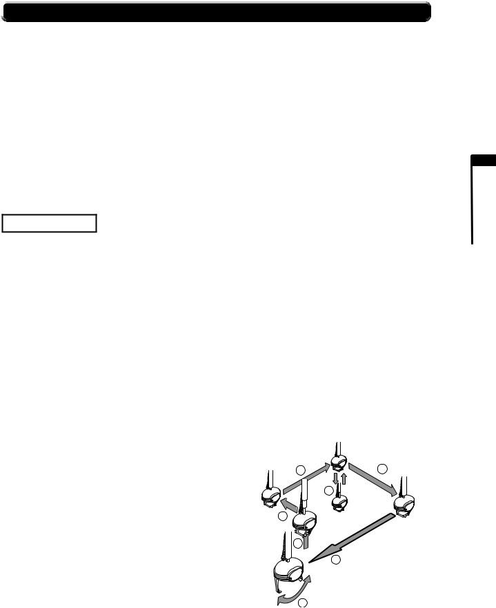
INITIALIZATION
During initialization, the UFO mechanism moves in the following sequence.
If an error is discovered during this series of operations, an error message is displayed and the UFO mechanism stops. (See Section 19)
1.UFO returns to home position (above the prize drop-out slot).
2.UFO moves toward the back of the cabinet. When it reaches the back limit, the UFO stops.
3.UFO moves sideways toward the center of the cabinet. When it reaches the center limit, the UFO stops.
4.UFO descends. When it reaches the lower limit, the UFO rises. Upon reaching the upper limit, the UFO stops.
5.UFO moves toward the front of the cabinet. When it reaches the front limit, the UFO stops.
6.UFO moves sideways toward the home position. Upon reaching the home position, the UFO stops. During stages 1 to 6 above, the UFO arm remains at the angle it assumed when the power supply was activated.
7.The UFO arm opens and closes.
8.After the arm closes, the catch sensor inside the UFO is initialized. This operation cannot be seen, but an error message will be displayed if there is an error in the sensor.
When the above initialization procedures are complete,
the customer-standby status is assumed. |
3 |
1 |
|
||
In this product, credits are remembered even if the |
|
4 |
power has been cut off. However, partial credits attained |
|
|
|
|
|
for multiple coins and bonus adder counts are deleted. |
|
|
If credits remain, the game-play status is assumed upon |
2 |
|
completion of initialization. |
|
|
|
1 |
|
6
7
FIG. 6-5 Initialization of UFO mechanism on player 1 side (left seat)
6 INSTALLATION
17
7 PRECAUTIONS WHEN MOVING
Carefully observe the following when moving the product. Failure to follow these instructions may result in personal injury during movement and/or damage to the cabinet.
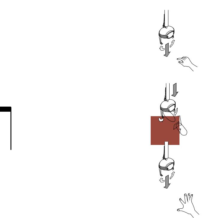
•Disconnect the power cord plug before moving the product. Be careful not to damage the power cable during movement.
•To move the product over the floor, retract the adjusters and have the casters come in contact with the floor.
special caution, as the
you lift the cabinet holding due to the weight of the
product. Careless may also cause
differences and the cabinet brackets and secure the secured in place, parts
Do not press on glass components.
Do not press on glass components while moving the product.
Otherwise glass may be damaged and cause injuries. Press on the cabinet's metal plates.
Move cabinet after casters are in contact with the floor.
FIG. 7b
18

8PRIZE REPLACEMENT
•Observe and follow the conditions listed below for prizes used with this product. Failure to follow the conditions could lead to product malfunctions and components may be damaged. The prizes themselves may also be damaged.
•Prizes can be stacked up to a maximum height of 40 cm (15.7 in), and 800 g (1.8 lb) or less in weight. If this limit is exceeded, there could be product malfunctions and components may be damaged. The prizes themselves may also be damaged.
•Exercise special care when handling glass components. Careless handling could cause damage to the glass. Fragments may also cause injury.
•If the larger arm L has been attached, enlarge the prize drop-out slot for largesize prizes. Otherwise there could be malfunctions or damage when the arm makes contact. The prizes themselves may also be damaged.
•Do not place prizes on, or suspend them from, the mechanism rail or moveable parts. This could cause product malfunctions and components may be damaged.
•Even if prizes meet the conditions set forth in these instructions, there could be unexpected faulty operations due to prize materials, shapes, and/or centers of gravity.
Use the operator’s
GLASS DOOR
Prizes can be stacked up to
a maximum height of 40 cm (15.7 in), and 800 g (1.8 lb) or less in weight.
8 PRIZEREPLACEMENT
19

CHANGING THE PRIZE DROP-OUT SLOT
If arm L has been attached for large-size prizes, enlarge the prize drop-out slot. (These instructions are for the 2P side drop-out slot.)
1. Loosen the 2 plastic-head screws. |
PLASTIC-HEAD SCREW (2) |
|
M4 |
8 PRIZEREPLACEMENT
PHOTO 8a
2.Support the bottom of the corner partition and slide it to widen the drop-out slot. Do not press down on the top of the corner partition (acrylic) to slide. Excessive force could damage components.
PHOTO 8b
3. Tighten the 2 plastic-head screws that were loosened.
PLASTIC-HEAD SCREW (2) M4
20 |
PHOTO 8c |

9 GAME CONTENT
The following explanations apply when the product functions normally. If the product behaves in a manner at variance with the content below, there may be a malfunction of some sort. Try to identify the cause of the problem immediately and repair it so that the unit can be operated normally.
HOW TO PLAY
In this product, the internal fluorescent lighting (for both billboard and internal lighting), and the left and right fluorescent lights light up when there is electrical continuity.
During customer-standby status, the UFO mechanism is stationary at the home position (above the prize drop-out slot).
All the buttons’lights on the control panel go out and the BGM outputs standby music. The BGM can also be set for no output.
Play fee and play count are displayed on the 7-seg displays on the control panel.
When in [Display mode], all of the 7-seg displays read “-”, the game cannot be played, and coins (or bills) are returned. (See Section 12.)
1.When coins are inserted, the time remaining (how long the UFO mechanism can be operated) and number of games remaining are displayed on 7-seg displays at the seat that is being playing
2.When 9 credits are exceeded, no more coins For example, if it is set so that 1 coin equals 2 credits when the next coin is inserted.At this no more coins can be accepted.
UFO mechanism is stationary at home position.
Fluorescent lamps are lit.
CONTROL PANEL
PRIZE DOOR
10 and
7-SEG DISPLAY |
LEVER |
CREDIT COUNT DISPLAY |
|
DOWN BUTTON
FIG. 9b Control Panel
3.When the lever is manipulated, time count begins and the UFO mechanism moves in the direction in which the lever is manipulated.
4.The arm of the UFO mechanism opens automatically whenever time runs out or the DOWN BUTTON has been pressed.
9 GAMECONTENT
21
9 GAMECONTENT
5.When the arm of the UFO mechanism opens completely, the UFO mechanism begins to descend.
6.Whenever the UFO mechanism comes in contact with a prize or other obstacle, or when the wire is stretched to its full length, the UFO mechanism stops descending and the arm closes.
7.After the arm has closed, the UFO mechanism begins to ascend. When it reaches the upper limit sensor, the UFO mechanism moves back to home position.
8.When the UFO mechanism reaches the home position, the arm opens.
9.When a prize passes the sensor, the fanfare rings.
10.When the arm opens and closes, 1 game is complete. If no credits remain at this time and the 7-seg display reads 0, the game is over. The BGM switches back to standby music. If credits remain, the next game can be played.
11.If the lever is not manipulated for 90 seconds, 1 credit is erased and the UFO mechanism arm opens and descends at the current position. The arm then closes and ascends and the UFO mechanism returns to home position.
FIG. 9c
22
10GAME BOARD
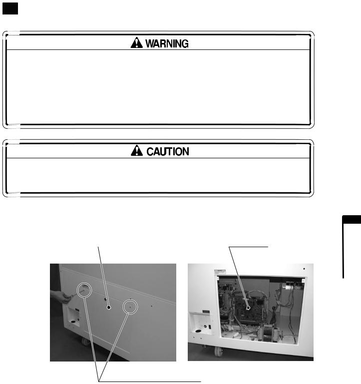
•Before performing work, be sure to turn the power off and unplug the electrical cord from the outlet. Performing the work without turning the power off can cause an electric shock or short circuit.
•Be careful not to damage the wires. Damaged wires may cause an electric shock, short circuit or present a risk of fire.
•Do not expose the Game Board, etc. for any reason. Doing so may cause electric shock or malfunctioning.
The chip components on IC boards can be damaged by electrostatic discharge from the human body. Before handling an IC board, always neutralize any static charge in the body by touching a grounded metal surface.
To access the game board, remove the 2 tamperproof screws on the back side of the cabinet, then use the master key to remove the back lid. The game board is inside.
BACK LID |
GAME BOARD |
TAMPERPROOF SCREW (2), chrome
M4 x 8
PHOTO 10
10
BOARD GAME
23

10
BOARD GAME
GAME BOARD CONFIGURATION DIAGRAM
GAME BD UCU: 834-14606 (R)
The DIP SWs on the game board are not used for game settings but must all be set to OFF.
|
CN7 |
CN8 |
|
NH4P |
|
|
RA40P |
|
CN5 |
834-14606(R) |
HEAT SINK |
|
|
|
NH12P |
|
|
CN15 |
|
|
NH5P |
|
|
|
ROM |
|
CN4 |
|
|
NH25P |
|
|
|
|
LED2 LED1 |
|
CN14 |
|
|
NH8P |
DIPSW |
CN3 |
|
|
RA16P |
POWER LED (This is lit when powering on.) |
|
|
||
|
RA50P |
RA34P |
|
CN2 |
CN1 |
FIG. 10
CONNECTORS AND INPUT/OUTPUT
[CN1 (JST RA34P)]: |
Switch,Analog Input |
[CN2 (JST RA50P)]: |
Switch, Sensor Input |
[CN3 (JST RA16P)]: |
Power Supply Input |
[CN4 (JST NH25P)]: |
Lamp, Catch Motor Output |
[CN5 (JST NH12P)]: |
Not used. |
[CN7 (JST RA40P)]: |
Meter,AC Motor Output |
[CN8 (JST NH4P)]: |
Speaker Output |
[CN9 (JST NH3P)]: |
Sound Volume Input |
[CN10 (JST NH16P)]: |
7-seg Display Output |
[CN11 (JST NH10P)]: |
7-seg Display Output |
[CN12 (JST NH6P)]: |
Not used. |
[CN14 (JST NH8P)]: |
Not used. |
[CN15 (JST NH5P)]: |
DIPSW BD Signal |
CN9
NH3P
CN18
NH16P
CN11
NH18P
CN12
NH6P
24

11 EXPLANATION OF TEST AND DATA DISPLAY
 11-1 SWITCH UNIT AND CASH BOX
Do not touch any areas other than those indicated. Touching other areas may cause accidents from electrical shocks or short circuits.
IMPORTANT
If the coin meter circuit is left detached, games cannot be played.
When you open the service door at the bottom of the cabinet front panel, you will find a switch unit deep inside. The functions of each button on the switch unit are as described below.
VFD DISPLAY
SELECT BUTTON (SELECT)
1P POWER KNOB (1P POWER)
SOUND VOLUME (VOL) 1P TEST BUTTON (TEST)
1P SERVICE BUTTON (SERVICE) 
METER 1 (METER 1)
METER 2 (METER 2) COIN METER 1P (COIN METER 1P)
FIG. 11-1
CLEAR BUTTON (CLEAR)
2P POWER KNOB (2P POWER)
2P SERVICE BUTTON (SERVICE)
SUB POWER SUPPLY SWITCH (SUB SW)
2P TEST BUTTON (TEST)
DIP SW 1  DIP SW 4 (See Section 12.) COIN METER 2P (COIN METER 2P)
- |
VFD Display: |
Monitor for displaying conditions such as income data. |
- |
1P Power Knob: |
Adjusts the strength of the 1P UFO mechanism spring. |
|
|
Adjustment ranges from 00 (weakest) to 99 (strongest). |
- |
2P Power Knob: |
Adjusts the strength of the 2P UFO mechanism spring. |
|
|
Adjustment ranges from 00 (weakest) to 99 (strongest). |
- |
Select Button: |
Used when switching VFD display content. |
- |
Clear Button: |
Used when clearing data displayed on VFD. |
- |
Test Button: |
Separated for 1P and 2P. Used when entering the test mode and when |
|
|
completing the test mode. |
11
DISPLAY DATA AND TEST OF EXPLANATION
25
 Loading...