


INTRODUCTION

CONTENTS OF TABLE
 TABLEOFCONTENTS
|
|
BEFORE USING THE PRODUCT ------------------------------------------------------- |
|
i |
|
|
|
|
TABLE OF CONTENTS --------------------------------------------------------------------- |
0 |
ii |
|
|
|
|
INTRODUCTION ---------------------------------------------------------------------------- |
0 |
v |
|
|
|
|
COPYRIGHT AND LICENSE MARKS --------------------------------------------------- |
0 |
vii |
|
|
|
|
|
|
0 |
|
|
|
1 |
-------------------------------------------------------------HANDLING PRECAUTIONS |
0 |
1 |
|
|
|
|
|
|
0 |
|
|
|
2 |
PRECAUTIONS REGARDING INSTALLATION LOCATION |
0 |
4 |
|
|
|
|
|||||
|
|
2.1 |
------------------------------------------------------------------------------LIMITATION OF USE |
0 |
4 |
|
|
|
2.2 |
OPERATION AREA ---------------------------------------------------------------------------------- |
0 |
5 |
|
|
|
|
|
0 |
|
|
|
3 |
PRECAUTIONS REGARDING PRODUCT OPERATION |
0 |
6 |
|
|
|
|
|||||
|
|
3.1 |
-------------------------------------------------------------------------------BEF0RE OPERATION |
0 |
6 |
|
|
|
3.2 |
PAYING ATTENTION TO CUSTOMER DURING OPERATION ------------------------------ |
0 |
8 |
|
|
|
|
|
0 |
|
|
|
|
|
|
|
|
|
|
4 |
PARTS DESCRIPTIONS |
0 |
10 |
|
|
|
|
|||||
|
|
|
|
0 |
|
|
|
|
|
|
|
|
|
|
5 |
ACCESSORIES |
0 |
11 |
|
|
|
|
|||||
|
|
|
|
0 |
|
|
|
|
|
|
|
|
|
|
6 |
ASSEMBLY AND INSTALLATION |
0 |
12 |
|
|
|
|
|||||
|
|
6.1 |
---------------------------------------------------------GENERAL ASSEMBLY INFORMATION |
0 |
14 |
|
|
|
6.2 |
FIXING THE BILLBOARD AND POP ------------------------------------------------------------- |
0 |
15 |
|
|
|
6.3 |
FIXING THE MAIN CABINET TO THE DPL CABINET ----------------------------------------- |
0 |
17 |
|
|
|
6.4 |
INSTALLATION AND FIXING IN PLACE -------------------------------------------------------- |
0 |
20 |
|
|
|
6.5 |
CONNECTING THE POWER CABLES ------------------------------------------------------------ |
0 |
21 |
|
|
|
6.6 |
CHECKING ASSEMBLY (SET UP) ---------------------------------------------------------------- |
0 |
22 |
|
|
|
|
|
0 |
|
|
|
7 |
PRECAUTIONS WHEN MOVING THE MACHINE |
0 |
28 |
|
|
|
|
|||||
|
|
|
|
0 |
|
|
|
8 |
GAME DESCRIPTION |
0 |
30 |
|
|
|
|
|||||
|
|
8.1 |
----------------------------------------------------------------------------------GAME OVERVIEW |
0 |
30 |
|
|
|
8.2 |
GAME SELECTION --------------------------------------------------------------------------------- |
0 |
31 |
|
|
|
8.3 |
CAR SELECTION ------------------------------------------------------------------------------------ |
0 |
34 |
|
|
|
8.4 |
CAR TRANSMISSION ------------------------------------------------------------------------------ |
0 |
37 |
|
|
|
8.5 |
TRACK SELECTION --------------------------------------------------------------------------------- |
0 |
38 |
|
|
|
8.6 |
ON SCREEN DISPLAY ----------------------------------------------------------------------------- |
0 |
39 |
|
|
|
8.7 |
DRIVERS VIEW - CAMERA ----------------------------------------------------------------------- |
0 |
40 |
|
|
|
8.8 |
HIGH SCORES --------------------------------------------------------------------------------------- |
0 |
41 |
|
|
|
|
|
|
|
|
ii

 TABLEOFCONTENTS
|
|
|
|
|
|
|
0 |
|
|
|
|
|
|
|
|
|
|
||
|
9 |
|
------------------------------------EXPLANATION OF TEST AND DATA DISPLAY |
0 |
42 |
|
|||
|
|
|
---------------------------------------------------------------9.1 SWITCH UNIT AND COIN METER |
0 |
44 |
|
|||
|
|
9.2 |
GAME TEST MODE --------------------------------------------------------------------------------- |
0 |
45 |
|
|||
|
|
|
|
9.21 |
SYSTEM INFORMATION ------------------------------------------------------------ |
0 |
47 |
|
|
|
|
|
|
9.22 |
INPUT TEST ---------------------------------------------------------------------------- |
0 |
48 |
|
|
|
|
|
|
9.23 |
OUTPUT TEST ------------------------------------------------------------------------- |
0 |
49 |
|
|
|
|
|
|
9.24 |
MOTION BASE TEST ----------------------------------------------------------------- |
0 |
50 |
|
|
|
|
|
|
9.25 |
COIN SETTINGS ---------------------------------------------------------------------- |
0 |
51 |
|
|
|
|
|
|
9.26 |
SOUND SETTINGS ------------------------------------------------------------------- |
0 |
52 |
|
|
|
|
|
|
9.27 |
SCREEN TEST ------------------------------------------------------------------------- |
0 |
53 |
|
|
|
|
|
|
9.28 |
NETWORK TEST ---------------------------------------------------------------------- |
0 |
55 |
|
|
|
|
|
|
9.29 |
CALIBRATE INPUTS ----------------------------------------------------------------- |
0 |
56 |
|
|
|
|
|
|
9.210 |
BOOK-KEEPING ---------------------------------------------------------------------- |
0 |
58 |
|
|
|
|
|
|
9.211 |
CLOCK SETTINGS -------------------------------------------------------------------- |
0 |
62 |
|
|
|
|
|
|
9.212 |
GAME SETTINGS --------------------------------------------------------------------- |
0 |
63 |
|
|
|
|
|
|
|
|
|
0 |
|
|
|
|
|
|
|
|
|
|
||
|
10 |
|
CONTROL COMPONENTS |
0 |
64 |
|
|||
|
|
|
|||||||
|
|
10.1 |
-------------------------------------------------STEERING WHEEL (EXPLODED DRAWING) |
0 |
65 |
|
|||
|
|
10.2 |
SHIFT LEVER ----------------------------------------------------------------------------------------- |
0 |
66 |
|
|||
|
|
|
|
10.21 |
REMOVING THE SHIFT LEVER ---------------------------------------------------- |
0 |
66 |
|
|
|
|
|
|
10.22 |
REPLACING THE SWITCH ---------------------------------------------------------- |
0 |
67 |
|
|
|
|
10.3 |
ACCELERATOR AND BRAKE --------------------------------------------------------------------- |
0 |
68 |
|
|||
|
|
|
|
10.31 |
VOLUME ADJUSTMENT AND REPLACEMENT --------------------------------- |
0 |
69 |
|
|
|
|
|
|
10.32 |
GREASING ----------------------------------------------------------------------------- |
0 |
71 |
|
|
|
|
10.4 |
HANDBRAKE ---------------------------------------------------------------------------------------- |
0 |
72 |
|
|||
|
|
|
|
10.41 |
REMOVING THE HANDBRAKE LEVER ------------------------------------------- |
0 |
72 |
|
|
|
|
|
|
10.42 |
REPLACING THE SWITCH ---------------------------------------------------------- |
0 |
73 |
|
|
|
|
10.5 |
MOTION SEAT --------------------------------------------------------------------------------------- |
0 |
74 |
|
|||
|
|
|
|
10.51 |
ASSEMBLED DRAWING ------------------------------------------------------------ |
0 |
74 |
|
|
|
|
|
|
10.52 |
EXPLODED VIEW - DRAWING ---------------------------------------------------- |
0 |
75 |
|
|
|
|
|
|
|
|
|
0 |
|
|
|
|
|
|
|
|
|
|
|
|
|
11 |
|
MONITOR UNIT |
|
0 |
77 |
|
||
|
|
---------------------------------------------------------------------------- |
|
||||||
|
|
11.1 |
----------------------------CAUTION AND WARNING CONCERNING MONITOR SAFETY |
0 |
77 |
|
|||
|
|
11.2 |
CLEANING CRT SURFACE ------------------------------------------------------------------------- |
0 |
78 |
|
|||
|
|
11.3 |
ADJUSTMENT PROCEDURES -------------------------------------------------------------------- |
0 |
79 |
|
|||
|
|
11.4 |
TROUBLE SHOOTING ------------------------------------------------------------------------------ |
0 |
83 |
|
|||
|
|
11.5 |
CHANGING THE LAMP ---------------------------------------------------------------------------- |
0 |
89 |
|
|||
|
|
|
|
|
|
|
0 |
|
|
|
|
|
|
|
|
|
|
|
|
|
|
|
|
|
|
|
|
|
|
CONTENTS OF TABLE
iii

 TABLEOFCONTENTS
|
|
|
|
|
|
|
|
|
|
12 |
----------------------------------------COIN SELECTOR AND CREDIT SETTINGS |
0 |
93 |
|
|
TABLE |
|
|
12.1 |
----------------------------------------------------------------CLEANING THE COIN SELECTOR |
0 |
93 |
|
|
|
12.3 |
SR3 OPTIONS - TEACH AND RUN PROGRAMMING ----------------------------------------- |
0 |
99 |
|
|
|
|
|
12.2 |
ADJUSTING PRICE OF PLAY ---------------------------------------------------------------------- |
0 |
95 |
|
OF |
|
|
|
|
0 |
|
|
CONTENTS |
|
|
|
|
|
|
|
|
13 |
------------------------------FLUORESCENT TUBES AND LAMP REPLACEMENT |
0 |
101 |
|
||
|
|
13.1 |
BILLBOARD TUBE REPLACEMENT |
0 |
102 |
|
|
|
|
|
|
||||
|
|
|
13.2 |
BILLB0ARD COLD CATHODE TUBE REPLACEMENT ---------------------------------------- |
0 |
104 |
|
|
|
|
13.3 |
REAR TUBE REPLACEMENT ---------------------------------------------------------------------- |
0 |
106 |
|
|
|
|
13.4 |
SPOT LAMP BULB REPLACEMENT -------------------------------------------------------------- |
0 |
108 |
|
|
|
|
13.5 |
BUTTON LAMPS - CONTROL PANEL ----------------------------------------------------------- |
0 |
110 |
|
|
|
|
|
|
0 |
|
|
|
|
14 |
-----------------------------------------------------------------PERIODIC INSPECTION |
0 |
112 |
|
|
|
|
|
|
|
0 |
|
|
|
|
|
|
|
|
|
|
|
|
15 |
-------------------------------------------------------------------TROUBLE SHOOTING |
0 |
114 |
|
|
|
|
|
15.1 |
----------------------TROUBLE SHOOTING - (WHEN NO ERROR MESSAGE IS SHOWN) |
0 |
114 |
|
|
|
|
|
|
0 |
|
|
|
|
|
|
|
|
|
|
|
|
16 |
----------------------------------------------------------------------------GAME BOARD |
0 |
118 |
|
|
|
|
|
16.1 |
---------------------------------------CONTROL BOARDS LOCATED IN THE DLP CABINET |
0 |
119 |
|
|
|
|
16.2 |
CONTROL BOARDS LOCATED IN THE MAIN CABINET ------------------------------------- |
0 |
121 |
|
|
|
|
|
|
0 |
|
|
|
|
17 |
--------------------------------------------------------------COMMUNICATION PLAY |
0 |
123 |
|
|
|
|
|
17.1 |
------------------------------------------------------------------INSTALLATION PRECAUTIONS |
0 |
124 |
|
|
|
|
17.2 |
CONNECTING THE COMMUNICATION CABLE ------------------------------------------------ |
0 |
125 |
|
|
|
|
17.3 |
NETWORK PLAY SETTINGS ----------------------------------------------------------------------- |
0 |
127 |
|
|
|
|
17.4 |
NETWORT PLAY PRECAUTIONS ----------------------------------------------------------------- |
0 |
128 |
|
|
|
|
|
|
0 |
|
|
|
|
|
|
|
|
|
|
|
|
18 |
--------------------------------------------------------------DESIGN RELATED PARTS |
0 |
129 |
|
|
|
|
|
|
|
|
|
|
|
|
19 |
-------------------------------------------------------------------------------PARTS LIST |
0 |
131 |
|
|
|
|
|
19.1 |
-------------------------------------------------------------------PARTS LIST - 'DPL' ASSEMBLY |
0 |
134 |
|
|
|
|
19.2 |
PARTS LIST - 'MAIN CABI' ASSEMBLY --------------------------------------------------------- |
0 |
144 |
|
|
|
|
19.3 |
PARTS LIST - INSTALLATION KIT ---------------------------------------------------------------- |
0 |
174 |
|
|
|
|
|
|
0 |
|
|
|
|
|
|
|
|
|
|
|
|
20 |
------------------------------------------------------WIRING COLOUR CODE TABLE |
0 |
181 |
|
|
|
|
|
|
|
0 |
|
|
|
|
|
|
|
|
|
|
|
|
21 |
----------------------------------------------------------------------WIRING DIAGRAM |
0 |
182 |
|
|
|
|
|
21.1 |
-------------------------------------------------------------------------WIRING DIAGRAM D 1-4 |
0 |
182 |
|
|
|
|
21.2 |
WIRING DIAGRAM D 2-4 ------------------------------------------------------------------------- |
0 |
183 |
|
|
|
|
21.3 |
WIRING DIAGRAM D 3-4 ------------------------------------------------------------------------- |
0 |
184 |
|
|
|
|
21.4 |
WIRING DIAGRAM D 3-43 ------------------------------------------------------------------------ |
0 |
185 |
|
|
|
|
|
|
|
|
|
iv
INTRODUCTION
This manual is intended to provide detailed descriptions together with all the necessary information covering the general operation of electronic assemblies, electro-mechanicals, servicing control, spare parts, etc. for the product, “SEGA - RALLY DELUXE
This manual is intended for the owners, personnel and managers in charge of operation of the product. Operate the product after carefully reading and sufficiently understanding the instructions
.
In the unlikely event that the product does not function correctly, DO NOT allow anyone other than a technician to touch the internal system. Turn off the power to the machine, making sure to unplug the electrical cord from the outlet, and contact the office listed below or the point of purchase for this product.
Use of this product is unlikely to cause physical injuries or damage to property. However, points that require special attention are indicated by bold text, the word “IMPORTANT” and the symbol below.
Indicates important information that, if ignored, may result in the mishandling of the product and cause faulty operation or damage to the product.
SEGA AMUSEMENTS EUROPE, LTD.
Block C, 42 Barwell Business Park, Chessington, Surrey. KT9 2NY United Kingdom.
Telephone: +44 (0) 208 391 8090 |
Facsimile: +44 (0) 208 391 8099 |
e-mail: mailbox@sega.co.uk |
http://www.sega-amusements.co.uk |
SPECIFICATIONS
MACHINE DETAILS |
|
|
Width : |
1500 mm |
(59.1 inches) |
Depth : |
2810 mm |
(110.6 inches |
Height |
2290 mm |
(90.2 inches) |
Weight |
430 kg |
(948 lbs) |
Power, Current |
720 W. |
3 Amps |
Voltage : |
220 - 230 Vac |
50Hz |
Monitor Type |
62” DLP Colour Display. |
|
NOTE:Thecontentshereindescribedaresubjecttochangewithoutnotice.
INTRODUCTION
INTRODUCTION
 Definitionof 'SiteMaintenencePersonnelorOtherQualifiedIndividuals
Procedures not described in this manual or marked as ‘to be carried out by site maintenance personnel or other qualified professionals’ should not be carried out by personnel without the necessary skill or technology. Work carried out by unqualified persons may cause serious accidents, including electrocution.
Parts replacement, maintenance inspections and troubleshooting should be carried out by site maintenance personnel or other qualified professionals. This manual includes directions for potentially dangerous procedures which should only be carried out by professionals with the appropriate specialised knowledge.
The site maintenance personnel or other qualified professionals mentioned in this manual are defined as follows:
Site maintenance personnel:
Individuals with experience in maintaining amusement equipment, vending machines, etc., working under the supervision of the owner/operator of this product to maintain machines within amusement facilities or similar premises by carrying out everyday procedures such as assembly, maintenance inspections, and replacement of units/expendable parts.
Activities to be carried out by site maintenance personnel:
Amusement equipment/vending machine assembly, maintenance inspection and replacement of units/ expendable parts.
Other qualified professionals:
Persons employed by amusement equipment manufacturers, or involved in design, production, testing or maintenance of amusement equipment. The individual should have either graduated from technical school or hold similar qualifications in electrical/electronics/mechanical engineering.
Activities to be carried out by other qualified professionals:
Amusement equipment/vending machine assembly, repair/adjustment of electrical/electronic/ mechanical parts.
vi
1 HANDLINGPRECAUTIONS
When installing or inspecting the machine, be very careful of the following points and pay attention to ensure that the player can enjoy the game safely.
Non-compliance with the following points or inappropriate handling running counter to the cautionary matters herein stated can cause personal injury or damage to the machine.
•Before performing work, be sure to turn the power off. Performing the work without turning the power off can cause an electric shock or short circuit. In the case work should be performed in the status of power on, this manual always states to that effect.
•To avoid an electric shock or short circuit, do not plug in or unplug quickly.
•To avoid an electric shock, do not plug in or unplug with a wet hand.
•Do not expose power cords or earth wires on the surface, (floor, passage, etc.). If exposed, the power cords and earth wires are susceptible to damage. Damaged cords and wires can cause an electric shock or short circuit.
•To avoid causing a fire or an electric shock, do not put things on or damage the power cords.
•When or after installing the product, do not unnecessarily pull the power cord. If damaged, the power cord can cause a fire or an electric shock.
•In case the power cord is damaged, ask for a replacement through where the product was purchased from or the office herein stated. Using the cord as is damaged can cause fire, an electric shock or leakage.
•Be sure to perform grounding appropriately. Inappropriate grounding can cause an electric shock.
•Be sure to use fuses meeting the specified rating. Using fuses exceeding the specified rating can cause a fire or an electric shock.
•Be sure that connections such as IC BD are made properly. Insufficient insertion can cause an electric shock.
•Specification changes, removal of equipment, conversion and/or addition, not designated by SEGA are not permitted.
•Failure to observe this may cause a fire or an electric shock. Non-compliance with this instruction can have a bad influence upon physical conditions of the players or the
onlookers, or result in injury during play.
•SEGA shall not be held responsible for damage, compensation for damage to a third party, caused by specification changes not designated by SEGA.
•If work or parts replacement not indicated in this manual is carried out, an accident may occur. If it is necessary to carry out work not indicated in this manual, be sure to have it done by the office indicated in this manual or by the point of purchase. Also, please inquire regarding
details of the work involved.
• Be sure to perform periodic maintenance inspections herein stated.
1 HANDLINGPRECAUTIONS
1 HANDLINGPRECAUTIONS
•For the IC board circuit inspections, only the logic tester is allowed. The use of a multiple-purpose tester is not permitted, so be careful in this regard.
•When cleaning the CRT surfaces, use a soft and dry cloth. Do not apply chemicals such as thinners, benzene, etc.
•Static electricity from your body may damage some electronics devices on the IC board. Before handling the IC board, touch a grounded metallic surface so that the static electricity can be discharged.
•Do not turn the power on and off continuously. Repeatedly turning the power on and off may cause product malfunction or parts damage.
•Some parts are not designed and manufactured specifically for this game machine. The manufacturers may discontinue, or change the specifications of such general-purpose parts. If this is the case, SEGA cannot repair or replace a failed game machine whether or not a warranty period has expired.
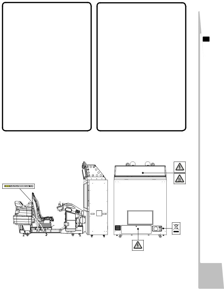
CONCERNING THE STICKER DISPLAY
This SEGA product has stickers attached describing the product manufacture No. (Serial No.) and Electrical Specifications. It also has a Sticker describing where to contact for repair and for purchasing parts.
When inquiring about or asking for repairs, mention the Serial No. and Name of Machine indicated on the Sticker. The Serial Number indicates the product register. Identical machines could have different parts depending on the date of production. Also, improvements and modifications might have been made after the publication of this manual. In order to ensure you order the correct parts, mention the Serial No. when contacting the applicable places.
CONCERNING THE WARNING LABELS
This SEGA product has warning displays on stickers, labels and/or printed instructions adhered/attached to or incorporated in the places where a potentially hazardous situation could arise. The warning displays are intended for accident prevention for customers and for avoiding hazardous situations relating to maintenance and servicing work. Some portions of the cabinet contain high voltage and may cause accidents if touched.
When performing maintenance, be very careful of the warning displays. It is especially important that any complex repairandreplacementworknotmentioned herein should be performed by those technical personnel who have knowledge of electricity and technical expertise. In order to prevent accidents, caution any customer ignoring the warnings to cease and desist immediately
1 HANDLINGPRECAUTIONS
2
REGARDING PRECAUTIONS LOCATION INSTALLATION
2 PRECAUTIONSREGARDINGINSTALLATIONLOCATION
This product is an indoor game machine. Do not install it outside. Even indoors, avoid installing in places mentioned below so as not to cause a fire, electric shock, injury and/or malfunction.
-Places subject to rain or water leakage, or places subject to high humidity in the proximity of an indoor swimming pool and/or shower, etc.
-Places subject to direct sunlight, or places subject to high temperatures in the proximity of heating units, etc.
-Places filled with inflammable gas or vicinity of highly inflammable/volatile chemicalsor hazardousmatter.
-Dusty places.
-Sloped surfaces.
-Places subject to any type of violent impact.
-Vicinity of anti-disaster facilities such as fire exits and fire extinguishers.
-Areas where the temperature exceeds the applicable temperature (ambient temperature) range of 5 to 30 degrees centigrade.
 2-1 LIMITATAION OF USE
Be sure to check the Electrical Specifications. Ensure that this product is compatible with the location’ s power supply, voltage, and frequency requirements. A plate describing Electrical Specifications is attached to the product. Non-compliance with the Electrical Specifications can cause a fire and electric shock.
This product requires a breaker and earth mechanism as part of the location facilities. Using the product without these can cause a fire and electric shock.
Ensure that the indoor wiring for the power supply is rated at 15 A or higher (AC single phase 100V ~ 120V area), and 7 A or higher (AC 220V ~ 240V area). Non-compliance with the Electrical Specifications can cause a fire and electric shock.
Be sure to use an independent power supply equipped with an earth leakage breaker. Using a power supply without an earth leakage breaker can cause an outbreak of fire if a power surge occurs.
Putting many loads on one electrical outlet can cause generation of heat and a fire resulting from overload.
When using an extension cord, ensure that the cord is rated at 15 A or higher (AC 100V ~ 120V area) and 7A or higher (AC 220V ~ 240V area). Using a cord rated lower than the specified rating can cause a fire and electric shock.
ELECTRICITY CONSUMPTION
MAX: 3A (AC230V~50HZ)

 2-2 OPERATIONAL AREA
• For the operation of this machine, secure a minimum area of 2.6m [W] x 3.5m [D].
The dimensions of the base periphery are established in consideration of ventilation, maintenance and customer passage. And if they fall and hit their head, there could be a very serious injury. Be sure to always secure enough space as prescribed in this manual.
•Be sure to provide sufficient space specified in this manual. Do not allow objects to block the ventilation ports. It can cause generation of heat and a fire.
•SEGA shall not be held responsible for damage or compensation for damage to a third party, resulting from the failure to observe this instruction.
INSTALLATION SPACE
2-2Fig01
In order to transport the machine into a building, the minimum necessary dimensions of the opening (of doors, etc,) are
1.2m, (W) and 1.7m, (H).
2-2Fig02
Before leaving the machine after Installation, make sure that the Castor Lift Adjusters are firmly positioned on the ground and that the machine is totaly stable.
2
REGARDING PRECAUTIONS LOCATION INSTALLATION

3
REGARDING PRECAUTION OPERATION PRODUCT
3 PRECAUTIONSREGARDINGPRODUCTOPERATION
 3.1 BEFORE OPERATION
In order to avoid accidents, check the following before starting the operation:
To ensure maximum safety for the players and the customers, ensure that where the product is operated has sufficient lighting to allow any warnings to be read.
Operation under insufficient lighting can cause bodily contact with each other, hitting accident, and/or trouble between customers.
Be sure to perform appropriate adjustment of the monitor (projector). For operation of this machine, do not leave monitor’ s flickering or deviation as is. Failure to observe this can have a bad influence upon the players’ or the customers’ physical conditions.
It is suggested to ensure a space allowing the players who feel sick while playing the game to take a rest.
Check if all of the adjusters are in contact with the surface. If they are not, the cabinet can move and cause an accident.
Do not put any heavy items on this product. Placing any heavy item on the product can cause a falling down accident or parts damage
Do not climb on the product. Climbing on the product can cause a falling down accident. To check the top portion of the product, use a step ladder.
To avoid electric shock, short circuit and / or parts damage, do not put the following items on or in the periphery of the product.
Flower vases, flower pots, cups, water tanks, cosmetics, receptacles or vessels containing chemicals or water.
3-1 Fig 01
Ensure that all adjusters are in contact with the floor.

 3.1 BEFORE OPERATION
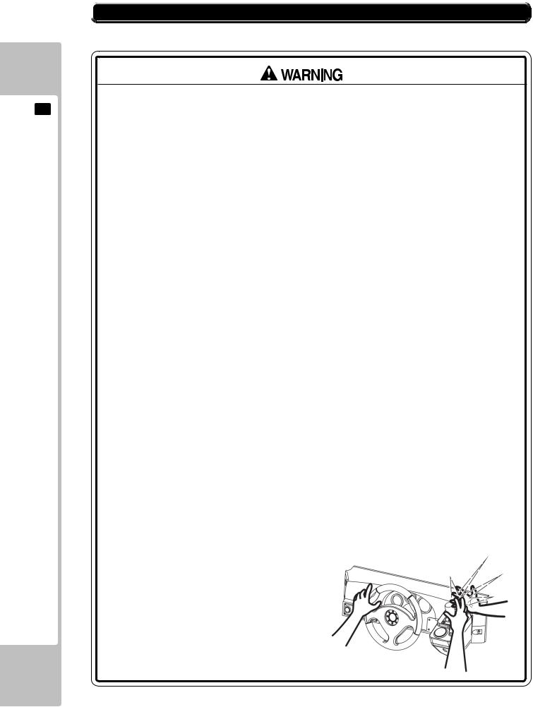
●During daily cleaning be sure to check the surface of the steering wheel, gear shifter and other parts that the player touches with his hands for damage, cracks or loose screws. If a player uses the machine while it is damaged, cracked or has a loose screw, the player may become injured.
●During daily cleaning, be sure to check the seat for any abnormality, wetness, etc. Failure to do this may result in deliberate tampering or negligence being left undetected.
●To avoid injury, be sure to provide sufficient space by considering the potentially crowded situation at the installation location. Insufficient installation space can cause contact, collisions and or trouble between customers.
●Do not attempt to clean this product using pressurised equipment such as a jet wash or hose. If for any reason this product becomes wet, do not use until it has completely dried.
Players hold the controller with their bare hands so it is recommended that wet towels (paper towels) be provided.
3
REGARDING PRECAUTIONS OPERATION PRODUCT
3
REGARDING PRECAUTION OPERATION PRODUCT
 3.2 PAYING ATTENTION TO CUSTOMERS DURING OPERATION
To avoid injury and trouble, be sure to pay attention to the behavior of visitors and players.
●For safety reasons, do not allow any of the following people to play the game.Those who need assistance when walking.
Those who have high blood pressure or heart problems.Those who have a neck or spinal cord problem.
Those who have experienced muscle convulsion or loss of consciousness while playing video games, etc.
Those who are intoxicated or under the influence of drugs.Pregnant women.
Those who are not in good health.
Those who do not follow the attendants instructions.
Those who cannot grasp the controller unit securely because of immobility in fingers, hands or arms.
Persons who disregard the products warning labels.
●Even players who have never been adversely affected by light stimulus might experience dizziness or headaches depending on their physical condition when playing the game. Small children are especially likely to experience these symptoms. Caution guardians of small children to keep watch on their children during play.
●Instruct those who feel sick during pay to seek medical advice or examination.
●To avoid injury from falling objects or electric shock hazard from spilt drinks, instruct the player not to place drinks or heavy items on the product.
●To avoid electric shock hazard and short circuit hazard, do not allow customers to puthandorfingersor anyotherextraneousmatterintotheopeningsof theproduct or small openings on or around the doors.
●To avoid falls resulting in injury, immediately stop the customer from leaning against or climbing on the product.
●Toavoidelectricshock and/orshortcircuithazard,donotallowcustomerstounplug the power plug without a justifiable reason.
●This product is intended for 1 Player only. Playing the game by 2 or more Players ridingonthe seattogethercancause falling downand collision accidents by striking heads, hands or elbows.
●Persons other than the player should not
be allowed to touch the controls during play. They may brush against or collide with the controls or the player, possibly resulting in accident.

 3.2 PAYING ATTENTION TO CUSTOMERS DURING OPERATION
●Customer should be warned not to place children on their laps while they play thegame. Doingsomay causethechildto become trapped between the player and the control panel and/or cause the machine to tip over.
Immediately stop such violent acts as hitting and kicking the product. Such violent acts can cause parts damage or cause the cabinet to fall over, resulting in injury.
3
REGARDING PRECAUTIONS OPERATION PRODUCT
4 PARTDESCRIPTIONS
ipt ions
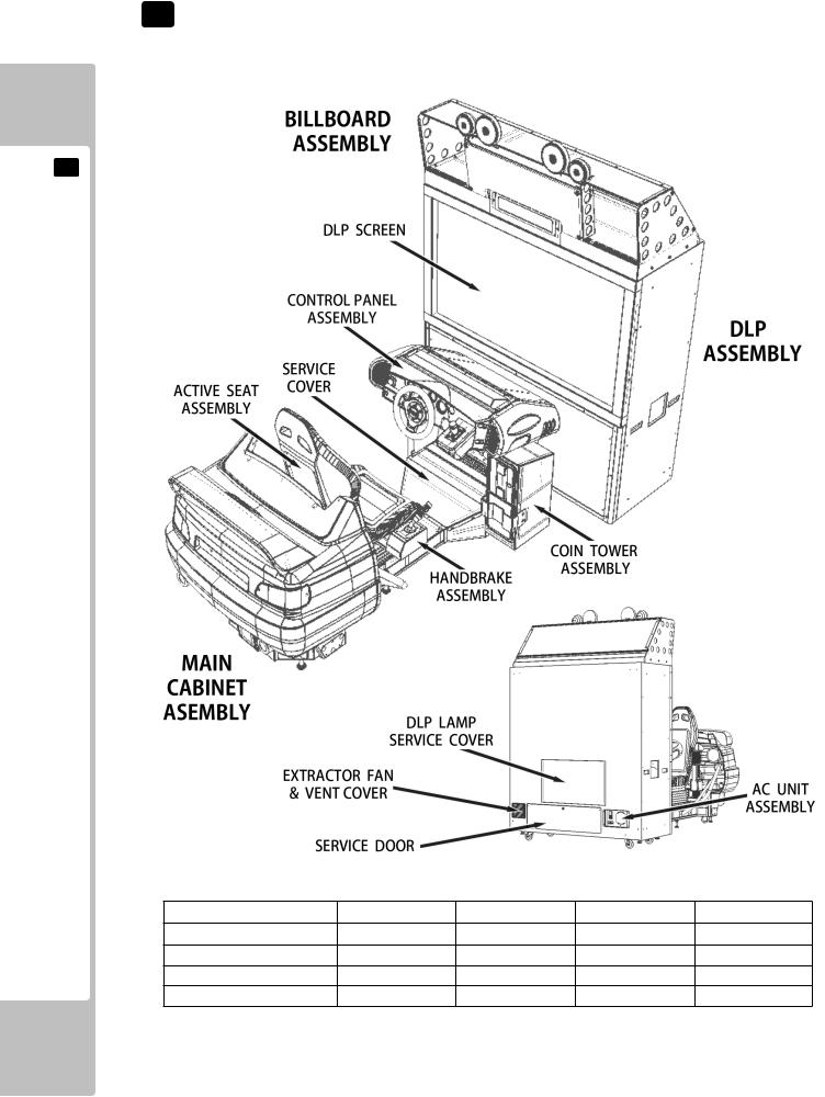
4 PartDescr
ITEM |
WIDTH (cm) |
DEPTH (cm) |
HEIGHT (cm) |
WEIGHT (kg) |
DLP CABINET |
1500 |
680 |
1690 |
160 |
MAIN CABINET |
1100 |
2130 |
1320 |
230 |
BILLBOARD |
1500 |
540 |
600 |
40 |
WHEN ASSEMBLED |
1500 |
2810 |
2290 |
430 |
10

5 ACCESSORIES
Confirmthattheaccessorieslistinthetablebelowarepresentwhensettinguptheproduct.
Accessoriesmarked“Spare”inthenotecolumnareconsumableitemsbutincludedasspares.
TABLE5A - ACCESSORIES
DESCRIPTION |
OWNERS MANUAL |
PT NUMBER (QTY) |
420-0005-01UK |
NOTE |
This Manual |
Parts not labeled with part numbers are as yet unregistered or cannot be registered. Be sure to handle all parts with care, as some parts are not available for purchase as separate items.
JOINT PLATE
SRS-0054UK (2)
TAMPER PROOF SCREW WRENCH
M4 540-0006-01 (1)
KEY MASTER 220-5793-2-A001 (2) For opening/closing the doors
KEY (2) CASHBOX DOOR
MAINS LEADS
LM1227 (1xUK)
LM1246 (1xEURO)
SEQ |
NUMBER |
DESCRIPTION |
QUANTITY |
NOTE |
1 |
SRS-5000UK |
ASSY - BILLBOARD |
1 |
|
4 |
SRS-0054UK |
JOINT BRKT |
2 |
|
101 |
440-CS0186UK |
STICKER C - EPILEPSY MULTI |
1 |
|
104 |
LM1227 |
UK MAINS LEAD 10A WITH PLUG |
1 |
|
105 |
LM1246 |
EUROLEAD 10A EUROPEAN SOCKET |
1 |
|
402 |
420-0005-01UK |
SERVICE MANUAL - SRS DX |
1 |
|
403 |
OS1019 |
SELF SEAL BAG 9 x12. 3/4 |
2 |
|
404 |
540-0006-01 |
WRENCH M4 TMP PRF |
1 |
|
408 |
SAECE-xxx |
DECLARATION OF CONFORMITY |
1 |
|
|
|
|
|
|
14 |
PK0 445 |
BOX - BILLBOARD ADH DX |
1 |
SPARE |
30 |
PK0440 |
PALLET - SRS DLP CABINET |
1 |
SPARE |
31 |
PK0441 |
SHRINK BAG - SRS DLP CABINET |
1 |
SPARE |
32 |
PK0442 |
PALLET - SRS FRONT CABINET |
1 |
SPARE |
33 |
PK0443 |
SHRINK BAG - SRS FRONT CABINET |
1 |
SPARE |
|
|
|
|
|
|
|
REMOTE CONTROL for 62" DLP |
1 |
|
5 ACCESSORIES
11
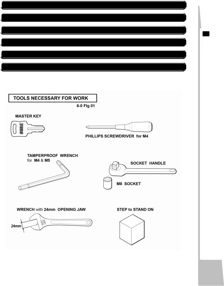
6 ASSEMBLY& INSTALLATION
6ASSEMBLY&INSTALLATION
•This work should be carried out by site maintenance personnel or other qualified professionals. Work performed by non-technical personnel can cause a severe accident such as electric shock. Failing to comply with this instruction can cause a
severe accident such as electric shock to the player during operation. If no one with proper technological expertise is available, request service from the office indicated in this document or the point of purchase so as to ensure safety.
•Perform assembly work by following the procedure herein stated. Failure to comply with the instructions can cause electric shock.
•Perform assembling as per this manual. Since this is a complex machine, incorrect assembling can cause an electric shock, machine damage and/or improper functioning as per specified performance.
•Whenassembling,morethanonepersonisrequired.Dependingontheassemblywork, there are some cases in which working by one person alone can cause personal injury or parts damage.
•Ensure that connectors are properly connected. Improper connections can cause electric shock.
•Be careful not to damage the wires. Damaged wires may cause electric shock or short circuit or present a risk of fire.
•Provide sufficient space so that assembling can be performed. Performing work in places with narrow space or low ceiling may cause an accident and assembly work to be difficult.
•To perform work safely and avoid serious accident such as the cabinet falling down, do not perform work in places where step-like grade differences, a ditch, or slope exist.
•Do not leave power cords, ground wires or network cables in areas of heavy foot traffic.
Doing so may cause them to become damaged, possibly resulting in electric shock and/or short circuits. When leaving wiring across a floor, always use a safety covers to protect the wires. (Wiring diameter : Power Cables - approx 0.8, Network Cable approx 0.5)
•The power cord for this product has a ground terminal. Make sure to use this ground termination when plugging it into an indoor outlet. Failure to ground the product could lead to electrocution. It can also cause malfunction.
•Do not use connectors other than those connected to and used by the game board at the time of shipment. Do not connect wires to unused connectors. This could cause the generation of heat or smoke, or a burnout.
•Wear appropriate work clothing so that work can be performed safely. Use gloves and safety shoes to prevent accidents or injuries.
•When installing a wire protection cover over a floor, use a material shaped so that no
one passing by will stumble over it. Using a material that could be stumbled over might lead to an accidental fall.
•Handle plastic parts with care. Excessive weight or pressure may cause them to break and the broken pieces may cause injury.
•Whenopening/closing,attaching/removing doorsor lids, becarefulthat yourhands or fingers etc, does not get caught in the apparatus.
12
Installationandassemblyofthisproductshouldtakeplaceinthefollowingsequence.
 6-1 GENERALASSEMBLYINFORMATION
 6-2 FITTING THE BILLBOARD AND POP
 6-3 FIXING THE MAIN CABINET TO THEDLP CABINET
 6-4 INSTALLATION AND SECURING IN PLACE
 6-5 CONNECTING POWER CABLE AND GROUND
 6-6 CHECKING ASSEMBLY (SETUP)
6 ASSEMBLY& INSTALLATION
13
 6-1 GENERAL ASSEMBLY INFORMATION
There are three MAIN Assemblies supplied, that have to be fitted together in order to complete the built of this machine :
A - DLP Cabinet |
(Video Cabinet Assembly) |
B - Billboard |
(Billboard Assembly) |
C - Main Cabinet |
(Seat and Control Assembly) |
6 ASSEMBLY& INSTALLATION
6-1Fig01
14
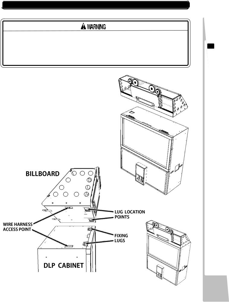
 6-2 FITTINGTHE BILLBOARDANDPOP
The BILLBOARD weighs 40Kgs (88.2lbs) therefore this installation should not be attempted single handed. It is recommended that three persons undertakethisparticularsectionoftheinstallation.
WORK SHOULD NOT BE UNDERTAKEN ON TOP OF THE CABINET WITHOUT THEUSEOFASUITABLESTEPORFOOTSTOOL.
6-2 Fig 01 Shows the components to be used during this section of the assembly.
6-2 Fig 02 Shows the key fixing points to be considered when attaching the BILLBOARD to the VIDEO Cabinet.
6-2 Fig 03 Shows the assembly completed at the end of this section of the assembly.
6-2Fig02
6-2Fig01
6-2Fig03
6 ASSEMBLY& INSTALLATION
15

6 ASSEMBLY& INSTALLATION
 6-2 FITTINGTHE BILLBOARDANDPOP
1Before starting the installation, locate the WIRE HARNESS in Billboard.
See(6-2Fig01)forthelocationswhere the Harness will be are found.
Once you have located the harness, get at least two people to lift the Billboard up onto the top of the Video Cabinet. Then with one person supporting the right hand side and the other lifting the left hand side up, locate the harnesses in the billboard and connect it to the connector in the top of the Video Cabinet.
6-2Fig04
2Once the Harness are connected, lower the Billboard down onto the top of the cabinet approx 25mm from the front edge of the cabinet making sure that the two Fixing Lugs located towards the front edge, go through the Lug Location Points cutouts the underside of the Billboard.
6-2Fig05
3When the Billboard sitting flat on top the Cabinet, flush with both sides and the Fixing Lugs through the location cutouts either end of the Billboard base.
Slide the Billboard forward until the bottom edge is flush with the front of the Cabinet. Check that both of the Fixing Lugs have located inside the Billboard and the front is firmly held.
Tocompletetheassemblyfitthefixing
screws through the Billboard into the |
6-2Fig06 |
cabinet along the back edge. |
16
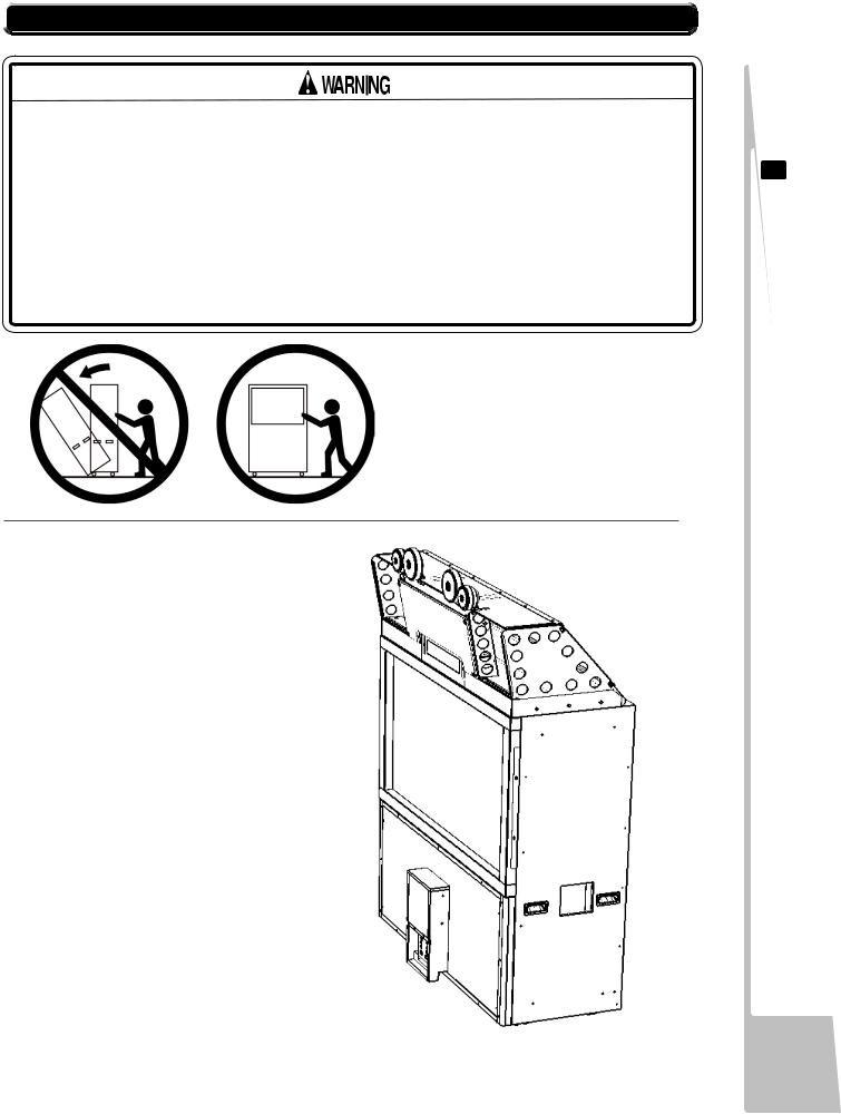
 6-3 FIXING THE MAIN CABINET TOTHE DLP CABINET
The DLP Cabinet with BILLBOARD Fitted Weights approx 200Kgs (441lbs) therefore a minimum of two people are required when moving this unit. Great care should be taken when handling or moving the unit otherwise personal injury may occur.
Whenever moving the unit, manipulate the movement from either end of the cabinet. Never push or pull the unit from the front or backside, as this can cause the unit to topple over causing damage to the unit and possible injury to any persons in the locality.
1Position the DLP Cabinet in the approx area of operation, allowing room to gain access from all sides.
6 ASSEMBLY& INSTALLATION
17
6 ASSEMBLY& INSTALLATION
 6-3 FIXING THE MAIN CABINET TOTHE DLP CABINET
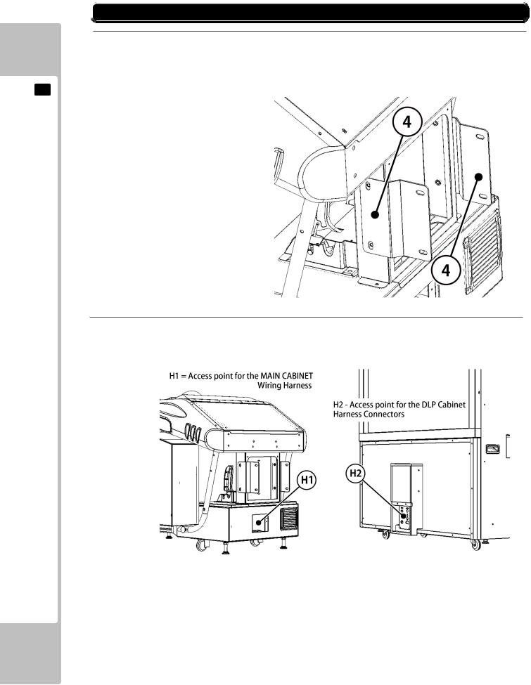
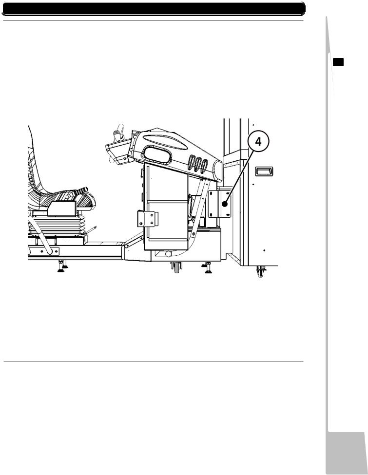
2 Preparing the Main Cabinet Unit for fixing to the DLP Unit
Take the 2x ‘JOINT BRACKETS’ (SRS-0054UK) ‘ITEM 4’ from the ‘Accessories Pack’ and loosely attach
them to the Main Cabinet assembly in the way shown in 6-3 Fig 02.
3 Connecting the Harness between the Main Cabinet and the DLP Units
Locate the Wiring Harness inside the Main Cabinet Assembly and extract the end with the connectors out through location ‘H1’ Match each connector and attach it to its mate that’ s fitted in the connector plate location ‘H2’
18
 6-3 FIXING THE MAIN CABINET TOTHE DLP CABINET
4Attaching the Main Cabinet Assembly to the DLP Assembly.
1 - Once all the Harness Connection have been made between the DLP and Main Cabinet Units, the Main Cabinet unit can be moved closing the gap between the two making sure that any of the wires in the harness do not get trapped in doing so.
2 - Check, when moving the Main Cabinet that the Joint Plates ‘4’ slide around the outside of the ‘Boxed Spacer’ section on the front of the DLP Unit.
3 - Once in position, locate and loosely attach the 4 fixing bolts through the Joint Plates ‘4’ into the Boxed Section of the DLP Unit. (2 Bolts each side).
4 - When the 4 bolts are in place, gently manipulate the Main Cabinet Unit in order to get the ‘Best Fit’ between the two Units, and then tighten all 8 bolts, the 4 attaching the Joint Plates to the DLP and the 4 attaching it to the Main Cabinet.
5Once the two Units have been fixed together, carefully move the machine to its final operating position. This should be undertaken by three people, one person either side of the DLP Unit and one behind the Main Cabinet and during the move, care must be taken not to overstress the connection point between the two Units otherwise damage could occur at this point. With the machine now positioned correctly you may proceed with securing it in place.
6 ASSEMBLY& INSTALLATION
19

6 ASSEMBLY& INSTALLATION
 6-4 INSTALLATION AND SECURING IN PLACE
During Installation, make sure that all the adjusters are in contact the floor.
Otherwise the cabinet could move, causing an accident.
.
‘SEGA RALLY 3’ consists of two Base Units : DLP Cabinet and MAIN Cabinet
6-4 Fig 01 - Shows the location of the Castors (C)
and Fixing Adjusters (A).
During the installation of each unit, the Fixing Adjustment should be performed to ensure that the units are stable.
DLP CABINET
4 x Adjusters and 4 x Castors
MAIN CABINET
6x Adjusters and 4x Castors
6-4- Fig 02 - Showing the correct details for Adjustment.
20
 6-5 CONNECTIONOFPOWERANDGROUND
•Use the power supply equipped with an earth leakage breaker. Use of power supply without such a breaker could result in fire if there is a current leakage.
•This product MUST be EARTHED. Ensure that the unit is properly connected to the INDOOR GROUND. Without proper grounding, customers could be electrocuted, product operation may not always be stable, and also introducing a risk of fire.
•Do not expose the power cords. If these are exposed, customers could stumble over them, for instance, and easily damage them. Additionally, if these lines are damaged, there could be a risk of electrical shock or short circuit. Set these lines at locations where they will not interfere with customer traffic, or attach covers to them.
•After laying out the power cord on the floor, be sure to always protect it. If the power cord is left exposed, it can easily be damaged, resulting in electrical shock.
•This product comes complete with POWER CORDS for the UK and EUROPEAN destinations, be sure to use the power cords supplied. If a power cord is to be replaced, be sure to replace it with the same specification as the one provided.
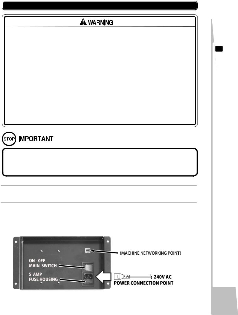
BeforeswitchingPowerON,makesurethatthe‘MachineGrounding’hasbeen establishedwithagroundwireinsidethe‘PowerCable’andthatthe‘MainsOutlet’supplyingthemachineisfittedwithasuitable‘EarthPoint’ ,
1ConfirmthattheMAINSWITCHissettoOFF,andbeforeswitchingONcompletethenextsection.
2Connect the ‘Power Cable’ supplied, into the IEC Inlet and Switch Unit located on the back of the machine (see 6-5 Fig 01) and a suitably ‘Grounded 240v AC Outlet Socket’ making sure that the ‘Power Cable’ is suitably protected and does not cause a hazard to players or other personnel that may be present.
6-5 Fig01
6 ASSEMBLY& INSTALLATION
21
 6-6 CHECKING ASSEMBLY - SET UP
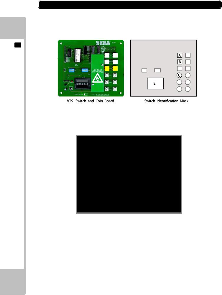
When he machine has been switched ON for the first time after installation, open the Coin Door and Press the ‘TEST’ Button which is located on the VTS board at the back thecompartment.Thiswillgiveentrytothe‘TESTMENU’
6 ASSEMBLY& INSTALLATION
A=TEST; |
B=SERVICE; |
C=VOLUMECONTROL; |
GAMETESTMODE
ThefollowingoptionsareavailablefromtheSystemMenuTest
TEST MENU
>>SYSTEM INFORMATION INPUT TEST
OUTPUT TEST MOTION BASE TEST COIN SETTINGS SOUND SETTINGS SCREEN TEST NETWORK TEST CALIBRATE INPUT BOOKKEEPING CLOCK SETTINGS GAME SETTINGS
RESET TO FACTORY DEFAULT EXIT
SELECT WITH SERVICE BUTTON
AND PRESS TEST BUTTON
Use the SERVICE Button to move the cursor to the desired test item.
Press the TEST Button to enter the selected item.
Thefollowing4TESTshouldbeselectedandcheckedindividuallytoprovethefunctionality ofallperipheralcomponents. ForfullinformationonalltheTestandSetUpProcedures, gotoChapter9-EXPLANATIONOFTESTANDDATADISPLAY
INPUT TEST |
Test routine for the INPUT peripherals. |
OUTPUT TEST |
Test routine for the OUTPUT peripherals. |
SOUND SETTINGS |
Test routine for the AUDIO OUTPUTS. |
SCREEN TEST |
Test routine for the DISPLAY SCREEN. |
EXIT |
To EXIT the Routine |
22

 6-6 CHECKING ASSEMBLY - SET UP
6-6 INPUTTEST
Select ‘INPUT TEST’ from the ‘Game Test Mode’ Menu to display ‘Input Test’ Menu.
|
INPUT TEST |
|
|
STEERING |
: 0000 |
|
BRAKE |
: 0000 |
|
ACCELERATOR |
: 0000 |
|
START BUTTON |
: OFF |
|
VIEW BUTTON |
: OFF |
|
HANDBRAKE |
: OFF |
|
GEARSHIFT UP |
: OFF |
|
GEARSHIFT DOWN |
: OFF |
|
MOTION STOP |
: OFF |
|
MOTION LIMIT L TOP |
: OFF |
|
MOTION LIMIT L BOTTOM |
: OFF |
|
MOTION LIMIT R TOP |
: OFF |
|
MOTION LIMIT R BOTTOM |
: OFF |
|
TEST BUTTON |
: OFF |
|
SERVICE BUTTON |
: OFF |
>> |
COIN INPUT |
: OFF |
EXIT |
|
PRESS TEST AND SERVICE BUTTON
TO EXIT
This TEST is used to Test the ‘SYSTEM INPUTS’ such as Steering, Pedals and Switches.
To implement the test, Operate each device listed and check the results on Screen.
STEERING |
00H = FULLY LEFT; 80H = CENTRE FFH = FULLY RIGHT. |
||
BRAKE |
00H = PEDAL FULLY UP; |
FFH = PEDAL FULLY DOWN . |
|
ACCELERATOR |
00H = PEDAL FULLY UP; |
FFH = PEDAL FULLY DOWN. |
|
START BUTTON |
ON = Pressed, |
OFF = Not Pressed . |
|
VIEW BUTTON |
ON = Pressed, |
OFF = Not Pressed. |
|
HANDBRAKE |
ON = Pressed, |
OFF = Not Pressed. |
|
GEAR SHIFT UP |
ON = Pressed, |
OFF = Not Pressed. |
|
GEAR SHIFT DOWN |
ON = Pressed, |
OFF = Not Pressed. |
|
MOTION LIMIT L TOP |
ON = Pressed, |
OFF = Not Pressed. |
|
MOTION LIMIT L BOTTOM |
ON = Pressed, |
OFF = Not Pressed. |
|
MOTION LIMIT R TOP |
ON = Pressed, |
OFF = Not Pressed. |
|
MOTION LIMIT R BOTTOM |
ON = Pressed, |
OFF = Not Pressed. |
|
TEST |
ON = Pressed, |
OFF = Not Pressed. |
|
SERVICE |
ON = Pressed, |
OFF = Not Pressed. |
|
COIN INPUT |
ON = Coin Signal from VTS; OFF = No Coin Signal from VTS. |
||
EXIT |
Press the TEST and SERVICE Buttons Simultaneously to EXIT. |
||
6 ASSEMBLY& INSTALLATION
23
 Loading...