

Page 1
Modicon M221 Logic C ontroller
EIO0000003313 02/2020
Modicon M221 Logic
Controller
Hardware Guide
02/2020
EIO0000003313.01
www.schneider-electric.com
Page 2

The information provided in this documentation contains general descriptions and/or technical
characteristics of the performance of the products contained herein. This documentation is not
intended as a substitute for and is not to be used for determining suitability or reliability of these
products for specific user applications. It is the duty of any such user or integrator to perform the
appropriate and complete risk analysis, evaluation and testing of the products with respect to the
relevant specific application or use thereof. Neither Schneider Electric nor any of its affiliates or
subsidiaries shall be responsible or liable for misuse of the information contained herein. If you
have any suggestions for improvements or amendments or have found errors in this publication,
please notify us.
You agree not to reproduce, other than for your own personal, noncommercial use, all or part of
this document on any medium whatsoever without permission of Schneider Electric, given in
writing. You also agree not to establish any hypertext links to this document or its content.
Schneider Electric does not grant any right or license for the personal and noncommercial use of
the document or its content, except for a non-exclusive license to consult it on an "as is" basis, at
your own risk. All other rights are reserved.
All pertinent state, regional, and local safety regulations must be observed when installing and
using this product. For reasons of safety and to help ensure compliance with documented system
data, only the manufacturer should perform repairs to components.
When devices are used for applications with technical safety requirements, the relevant
instructions must be followed.
Failure to use Schneider Electric software or approved software with our hardware products may
result in injury, harm, or improper operating results.
Failure to observe this information can result in injury or equipment damage.
© 2020 Schneider Electric. All rights reserved.
2 EIO0000003313 02/2020
Page 3

Table of Contents
Safety Information. . . . . . . . . . . . . . . . . . . . . . . . . . . . . . 7
About the Book . . . . . . . . . . . . . . . . . . . . . . . . . . . . . . . . 9
Part I Modicon M221 Logic Controller Introduction . . . . . .
Chapter 1 M221 General Overview . . . . . . . . . . . . . . . . . . . . . . . . . 19
TM221C Logic Controller Description . . . . . . . . . . . . . . . . . . . . . . . . .
TM221M Logic Controller Description . . . . . . . . . . . . . . . . . . . . . . . . .
Maximum Hardware Configuration . . . . . . . . . . . . . . . . . . . . . . . . . . .
TMC2 Cartridges . . . . . . . . . . . . . . . . . . . . . . . . . . . . . . . . . . . . . . . . .
TM3 Expansion Modules . . . . . . . . . . . . . . . . . . . . . . . . . . . . . . . . . . .
TM2 Expansion Modules . . . . . . . . . . . . . . . . . . . . . . . . . . . . . . . . . . .
Accessories . . . . . . . . . . . . . . . . . . . . . . . . . . . . . . . . . . . . . . . . . . . . .
Chapter 2 M221 Features . . . . . . . . . . . . . . . . . . . . . . . . . . . . . . . . 53
Real Time Clock (RTC) . . . . . . . . . . . . . . . . . . . . . . . . . . . . . . . . . . . .
Input Management. . . . . . . . . . . . . . . . . . . . . . . . . . . . . . . . . . . . . . . .
Output Management . . . . . . . . . . . . . . . . . . . . . . . . . . . . . . . . . . . . . .
Run/Stop . . . . . . . . . . . . . . . . . . . . . . . . . . . . . . . . . . . . . . . . . . . . . . .
SD Card . . . . . . . . . . . . . . . . . . . . . . . . . . . . . . . . . . . . . . . . . . . . . . .
Chapter 3 M221 Installation . . . . . . . . . . . . . . . . . . . . . . . . . . . . . . 79
3.1 M221 Logic Controller General Rules for Implementing . . . . . . . . . . .
Environmental Characteristics. . . . . . . . . . . . . . . . . . . . . . . . . . . . . . .
Certifications and Standards . . . . . . . . . . . . . . . . . . . . . . . . . . . . . . . .
3.2 M221 Logic Controller Installation . . . . . . . . . . . . . . . . . . . . . . . . . . . .
Installation and Maintenance Requirements . . . . . . . . . . . . . . . . . . . .
TM221C Logic Controller Mounting Positions and Clearances . . . . . .
TM221M Logic Controller Mounting Positions and Clearances. . . . . .
Top Hat Section Rail (DIN rail) . . . . . . . . . . . . . . . . . . . . . . . . . . . . . .
Installing and Removing the Controller with Expansions. . . . . . . . . . .
Direct Mounting on a Panel Surface . . . . . . . . . . . . . . . . . . . . . . . . . .
3.3 M221 Electrical Requirements. . . . . . . . . . . . . . . . . . . . . . . . . . . . . . .
Wiring Best Practices . . . . . . . . . . . . . . . . . . . . . . . . . . . . . . . . . . . . .
DC Power Supply Characteristics and Wiring . . . . . . . . . . . . . . . . . . .
AC Power Supply Characteristics and Wiring . . . . . . . . . . . . . . . . . . .
Grounding the M221 System. . . . . . . . . . . . . . . . . . . . . . . . . . . . . . . .
17
20
25
30
34
36
45
49
54
61
65
69
72
80
81
85
86
87
90
93
96
100
104
106
107
114
119
122
EIO0000003313 02/2020 3
Page 4

Part II Modicon TM221C Logic Controller. . . . . . . . . . . . . .
127
Chapter 4 TM221C16R . . . . . . . . . . . . . . . . . . . . . . . . . . . . . . . . . . . 129
TM221C16R Presentation . . . . . . . . . . . . . . . . . . . . . . . . . . . . . . . . . .
129
Chapter 5 TM221CE16R. . . . . . . . . . . . . . . . . . . . . . . . . . . . . . . . . . 135
TM221CE16R Presentation . . . . . . . . . . . . . . . . . . . . . . . . . . . . . . . . .
135
Chapter 6 TM221C16T . . . . . . . . . . . . . . . . . . . . . . . . . . . . . . . . . . . 139
TM221C16T Presentation . . . . . . . . . . . . . . . . . . . . . . . . . . . . . . . . . .
139
Chapter 7 TM221CE16T . . . . . . . . . . . . . . . . . . . . . . . . . . . . . . . . . . 143
TM221CE16T Presentation . . . . . . . . . . . . . . . . . . . . . . . . . . . . . . . . .
143
Chapter 8 TM221C16U . . . . . . . . . . . . . . . . . . . . . . . . . . . . . . . . . . . 147
TM221C16U Presentation . . . . . . . . . . . . . . . . . . . . . . . . . . . . . . . . . .
147
Chapter 9 TM221CE16U. . . . . . . . . . . . . . . . . . . . . . . . . . . . . . . . . . 151
TM221CE16U Presentation . . . . . . . . . . . . . . . . . . . . . . . . . . . . . . . . .
151
Chapter 10 TM221C24R . . . . . . . . . . . . . . . . . . . . . . . . . . . . . . . . . . . 157
TM221C24R Presentation . . . . . . . . . . . . . . . . . . . . . . . . . . . . . . . . . .
157
Chapter 11 TM221CE24R. . . . . . . . . . . . . . . . . . . . . . . . . . . . . . . . . . 161
TM221CE24R Presentation . . . . . . . . . . . . . . . . . . . . . . . . . . . . . . . . .
161
Chapter 12 TM221C24T . . . . . . . . . . . . . . . . . . . . . . . . . . . . . . . . . . . 165
TM221C24T Presentation . . . . . . . . . . . . . . . . . . . . . . . . . . . . . . . . . .
165
Chapter 13 TM221CE24T . . . . . . . . . . . . . . . . . . . . . . . . . . . . . . . . . . 169
TM221CE24T Presentation . . . . . . . . . . . . . . . . . . . . . . . . . . . . . . . . .
169
Chapter 14 TM221C24U . . . . . . . . . . . . . . . . . . . . . . . . . . . . . . . . . . . 173
TM221C24U Presentation . . . . . . . . . . . . . . . . . . . . . . . . . . . . . . . . . .
173
Chapter 15 TM221CE24U. . . . . . . . . . . . . . . . . . . . . . . . . . . . . . . . . . 179
TM221CE24U Presentation . . . . . . . . . . . . . . . . . . . . . . . . . . . . . . . . .
179
Chapter 16 TM221C40R . . . . . . . . . . . . . . . . . . . . . . . . . . . . . . . . . . . 185
TM221C40R Presentation . . . . . . . . . . . . . . . . . . . . . . . . . . . . . . . . . .
185
Chapter 17 TM221CE40R. . . . . . . . . . . . . . . . . . . . . . . . . . . . . . . . . . 191
TM221CE40R Presentation . . . . . . . . . . . . . . . . . . . . . . . . . . . . . . . . .
191
Chapter 18 TM221C40T . . . . . . . . . . . . . . . . . . . . . . . . . . . . . . . . . . . 197
TM221C40T Presentation . . . . . . . . . . . . . . . . . . . . . . . . . . . . . . . . . .
197
Chapter 19 TM221CE40T . . . . . . . . . . . . . . . . . . . . . . . . . . . . . . . . . . 203
TM221CE40T Presentation . . . . . . . . . . . . . . . . . . . . . . . . . . . . . . . . .
203
Chapter 20 TM221C40U . . . . . . . . . . . . . . . . . . . . . . . . . . . . . . . . . . . 209
TM221C40U Presentation . . . . . . . . . . . . . . . . . . . . . . . . . . . . . . . . . .
209
Chapter 21 TM221CE40U. . . . . . . . . . . . . . . . . . . . . . . . . . . . . . . . . . 215
TM221CE40U Presentation . . . . . . . . . . . . . . . . . . . . . . . . . . . . . . . . .
215
4 EIO0000003313 02/2020
Page 5

Chapter 22 Embedded I/O Channels . . . . . . . . . . . . . . . . . . . . . . . . 221
Digital Inputs . . . . . . . . . . . . . . . . . . . . . . . . . . . . . . . . . . . . . . . . . . . .
Relay Outputs . . . . . . . . . . . . . . . . . . . . . . . . . . . . . . . . . . . . . . . . . . .
Regular and Fast Transistor Outputs . . . . . . . . . . . . . . . . . . . . . . . . .
Analog Inputs . . . . . . . . . . . . . . . . . . . . . . . . . . . . . . . . . . . . . . . . . . .
Part III Modicon TM221M Logic Controller. . . . . . . . . . . . . .
222
239
247
256
261
Chapter 23 TM221M16R / TM221M16RG . . . . . . . . . . . . . . . . . . . . 263
TM221M16R / TM221M16RG Presentation . . . . . . . . . . . . . . . . . . . .
TM221M16R / TM221M16RG Digital Inputs . . . . . . . . . . . . . . . . . . . .
TM221M16R / TM221M16RG Digital Outputs. . . . . . . . . . . . . . . . . . .
TM221M16R / TM221M16RG Analog Inputs . . . . . . . . . . . . . . . . . . .
264
268
272
276
Chapter 24 TM221ME16R / TM221ME16RG . . . . . . . . . . . . . . . . . . 281
TM221ME16R / TM221ME16RG Presentation . . . . . . . . . . . . . . . . . .
TM221ME16R / TM221ME16RG Digital Inputs. . . . . . . . . . . . . . . . . .
TM221ME16R / TM221ME16RG Digital Outputs . . . . . . . . . . . . . . . .
TM221ME16R / TM221ME16RG Analog Inputs . . . . . . . . . . . . . . . . .
282
287
291
295
Chapter 25 TM221M16T / TM221M16TG . . . . . . . . . . . . . . . . . . . . . 299
TM221M16T / TM221M16TG Presentation. . . . . . . . . . . . . . . . . . . . .
TM221M16T / TM221M16TG Digital Inputs . . . . . . . . . . . . . . . . . . . .
TM221M16T / TM221M16TG Digital Outputs . . . . . . . . . . . . . . . . . . .
TM221M16T / TM221M16TG Analog Inputs . . . . . . . . . . . . . . . . . . . .
300
304
309
314
Chapter 26 TM221ME16T / TM221ME16TG . . . . . . . . . . . . . . . . . . 319
TM221ME16T / TM221ME16TG Presentation . . . . . . . . . . . . . . . . . .
TM221ME16T / TM221ME16TG Digital Inputs . . . . . . . . . . . . . . . . . .
TM221ME16T / TM221ME16TG Digital Outputs. . . . . . . . . . . . . . . . .
TM221ME16T / TM221ME16TG Analog Inputs . . . . . . . . . . . . . . . . .
320
326
331
336
Chapter 27 TM221M32TK . . . . . . . . . . . . . . . . . . . . . . . . . . . . . . . . . 341
TM221M32TK Presentation. . . . . . . . . . . . . . . . . . . . . . . . . . . . . . . . .
TM221M32TK Digital Inputs . . . . . . . . . . . . . . . . . . . . . . . . . . . . . . . .
TM221M32TK Digital Outputs . . . . . . . . . . . . . . . . . . . . . . . . . . . . . . .
TM221M32TK Analog Inputs. . . . . . . . . . . . . . . . . . . . . . . . . . . . . . . .
342
346
351
356
Chapter 28 TM221ME32TK. . . . . . . . . . . . . . . . . . . . . . . . . . . . . . . . 361
TM221ME32TK Presentation . . . . . . . . . . . . . . . . . . . . . . . . . . . . . . .
TM221ME32TK Digital Inputs . . . . . . . . . . . . . . . . . . . . . . . . . . . . . . .
TM221ME32TK Digital Outputs. . . . . . . . . . . . . . . . . . . . . . . . . . . . . .
TM221ME32TK Analog Inputs . . . . . . . . . . . . . . . . . . . . . . . . . . . . . .
362
367
372
377
EIO0000003313 02/2020 5
Page 6

Part IV Modicon M221 Logic Controller Communication . . .
381
Chapter 29 Integrated Communication Ports . . . . . . . . . . . . . . . . . . . 383
USB Mini-B Programming Port . . . . . . . . . . . . . . . . . . . . . . . . . . . . . .
Ethernet Port . . . . . . . . . . . . . . . . . . . . . . . . . . . . . . . . . . . . . . . . . . . .
Serial Line 1 . . . . . . . . . . . . . . . . . . . . . . . . . . . . . . . . . . . . . . . . . . . .
Serial Line 2 . . . . . . . . . . . . . . . . . . . . . . . . . . . . . . . . . . . . . . . . . . . . .
384
386
389
393
Chapter 30 Connecting the M221 Logic Controller to a PC . . . . . . . . 397
Connecting the Controller to a PC . . . . . . . . . . . . . . . . . . . . . . . . . . . .
Glossary . . . . . . . . . . . . . . . . . . . . . . . . . . . . . . . . . . . . . . . . .
Index . . . . . . . . . . . . . . . . . . . . . . . . . . . . . . . . . . . . . . . . .
397
401
407
6 EIO0000003313 02/2020
Page 7
Safety Information
Important Information
NOTICE
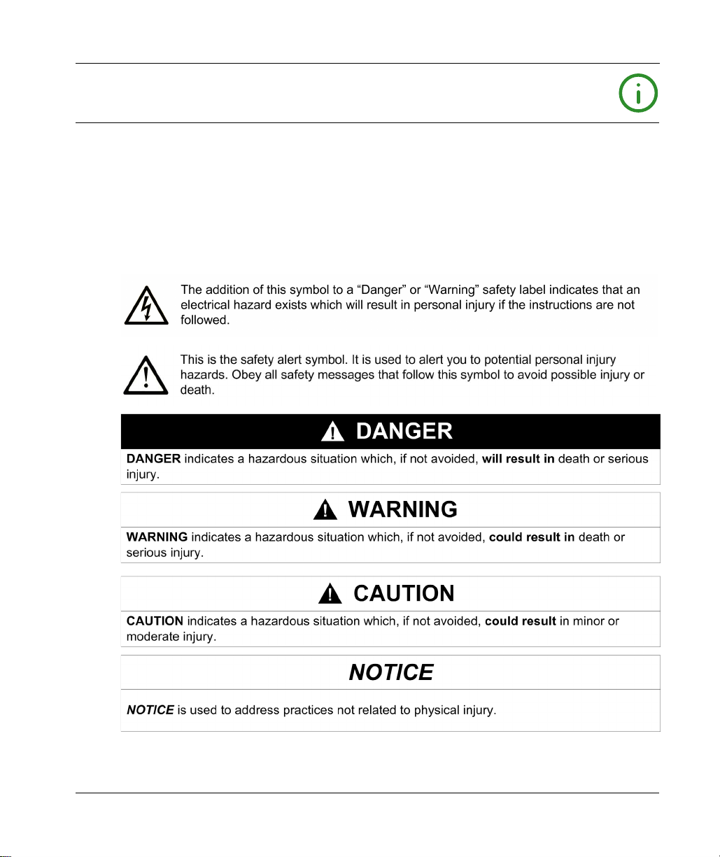
Read these instructions carefully, and look at the equipment to become familiar with the device
before trying to install, operate, service, or maintain it. The following special messages may appear
throughout this documentation or on the equipment to warn of potential hazards or to call attention
to information that clarifies or simplifies a procedure.
EIO0000003313 02/2020 7
Page 8

PLEASE NOTE
Electrical equipment should be installed, operated, serviced, and maintained only by qualified
personnel. No responsibility is assumed by Schneider Electric for any consequences arising out of
the use of this material.
A qualified person is one who has skills and knowledge related to the construction and operation
of electrical equipment and its installation, and has received safety training to recognize and avoid
the hazards involved.
QUALIFICATION OF PERSONNEL
Only appropriately trained persons who are familiar with and understand the contents of this
manual and all other pertinent product documentation are authorized to work on and with this
product.
The qualified person must be able to detect possible hazards that may arise from parameterization,
modifying parameter values and generally from mechanical, electrical, or electronic equipment.
The qualified person must be familiar with the standards, provisions, and regulations for the
prevention of industrial accidents, which they must observe when designing and implementing the
system.
INTENDED USE
The products described or affected by this document, together with software, accessories, and
options, are programmable logic controllers (referred to herein as “logic controllers”), intended for
industrial use according to the instructions, directions, examples, and safety information contained
in the present document and other supporting documentation.
The product may only be used in compliance with all applicable safety regulations and directives,
the specified requirements, and the technical data.
Prior to using the product, you must perform a risk assessment in view of the planned application.
Based on the results, the appropriate safety-related measures must be implemented.
Since the product is used as a component in an overall machine or process, you must ensure the
safety of persons by means of the design of this overall system.
Operate the product only with the specified cables and accessories. Use only genuine accessories
and spare parts.
Any use other than the use explicitly permitted is prohibited and can result in unanticipated
hazards.
8 EIO0000003313 02/2020
Page 9

About the Book
At a Glance
Document Scope
Use this document to:
Install and operate your M221 Logic Controller.
Connect the M221 Logic Controller to a programming device equipped with EcoStruxure
Machine Expert - Basic software.
Interface the M221 Logic Controller with I/O expansion modules, HMI and other devices.
Familiarize yourself with the M221 Logic Controller features.
NOTE: Read and understand this document and all related documents
installing, operating, or maintaining your controller.
Validity Note
This document has been updated for the release of EcoStruxure
The technical characteristics of the devices described in this manual also appear online.
The characteristics that are presented in the present document should be the same as those
characteristics that appear online. In line with our policy of constant improvement, we may revise
content over time to improve clarity and accuracy. If you see a difference between the document
and online information, use the online information as your reference.
For product compliance and environmental information (RoHS, REACH, PEP, EOLI, etc.), go to
www.schneider-electric.com/green-premium
(see page 10)
TM
Machine Expert - Basic V1.1.
before
.
EIO0000003313 02/2020 9
Page 10

Related Documents
Title of Documentation Reference Number
Modicon M221 Logic Controller - Programming Guide
Modicon TMH2GDB Remote Graphic Display - User Guide
Modicon TMC2 Cartridges - Hardware Guide
Modicon TM3 Digital I/O Modules - Hardware Guide
Modicon TM3 Analog I/O Modules - Hardware Guide
EIO0000003297 (ENG)
EIO0000003298 (FRE)
EIO0000003299 (GER)
EIO0000003300 (SPA)
EIO0000003301 (ITA)
EIO0000003302 (CHS)
EIO0000003304 (TUR)
EIO0000003303 (POR)
EIO0000003321 (ENG)
EIO0000003322 (FRE)
EIO0000003323 (GER)
EIO0000003324 (SPA)
EIO0000003325 (ITA)
EIO0000003326 (CHS)
EIO0000003328 (TUR)
EIO0000003327 (POR)
EIO0000003337 (ENG)
EIO0000003338 (FRE)
EIO0000003339 (GER)
EIO0000003340 (SPA)
EIO0000003341 (ITA)
EIO0000003342 (CHS)
EIO0000003344 (TUR)
EIO0000003343 (POR)
EIO0000003125 (ENG)
EIO0000003126 (FRE)
EIO0000003127 (GER)
EIO0000003128 (SPA)
EIO0000003129 (ITA)
EIO0000003130 (CHS)
EIO0000003425 (TUR)
EIO0000003424 (POR)
EIO0000003131 (ENG)
EIO0000003132 (FRE)
EIO0000003133 (GER)
EIO0000003134 (SPA)
EIO0000003135 (ITA)
EIO0000003136 (CHS)
EIO0000003427 (TUR)
EIO0000003426 (POR)
10 EIO0000003313 02/2020
Page 11

Title of Documentation Reference Number
Modicon TM3 Expert I/O Modules - Hardware Guide
EIO0000003137 (ENG)
EIO0000003138 (FRE)
EIO0000003139 (GER)
EIO0000003140 (SPA)
EIO0000003141 (ITA)
EIO0000003142 (CHS)
EIO0000003429 (TUR)
EIO0000003428 (POR)
Modicon TM3 Safety Modules - Hardware Guide
EIO0000003353 (ENG)
EIO0000003354 (FRE)
EIO0000003355 (GER)
EIO0000003356 (SPA)
EIO0000003357 (ITA)
EIO0000003358 (CHS)
EIO0000003360 (TUR)
EIO0000003359 (POR)
Modicon TM3 Transmitter and Receiver Modules - Hardware Guide
EIO0000003143 (ENG)
EIO0000003144 (FRE)
EIO0000003145 (GER)
EIO0000003146 (SPA)
EIO0000003147 (ITA)
EIO0000003148 (CHS)
EIO0000003431 (TUR)
EIO0000003430 (POR)
TM221C DC Logic Controller - Instruction Sheet
TM221C AC Logic Controller - Instruction Sheet
TM221M Logic Controller - Instruction Sheet
EAV48550
EAV58623
HRB59602
You can download these technical publications and other technical information from our website
at https://www.se.com/ww/en/download/ .
EIO0000003313 02/2020 11
Page 12
Product Related Information
HAZARD OF ELECTRIC SHOCK, EXPLOSION OR ARC FLASH
Disconnect all power from all equipment including connected devices prior to removing any
covers or doors, or installing or removing any accessories, hardware, cables, or wires except
under the specific conditions specified in the appropriate hardware guide for this equipment.
Always use a properly rated voltage sensing device to confirm the power is off where and when
indicated.
Replace and secure all covers, accessories, hardware, cables, and wires and confirm that a
proper ground connection exists before applying power to the unit.
Use only the specified voltage when operating this equipment and any associated products.
Failure to follow these instructions will result in death or serious injury.
POTENTIAL FOR EXPLOSION
Only use this equipment in non-hazardous locations, or in locations that comply with Class I,
Division 2, Groups A, B, C and D.
Do not substitute components which would impair compliance to Class I, Division 2.
Do not connect or disconnect equipment unless power has been removed or the location is
known to be non-hazardous.
Do not use the USB port(s), if so equipped, unless the location is known to be non-hazardous.
Failure to follow these instructions will result in death or serious injury.
DANGER
DANGER
12 EIO0000003313 02/2020
Page 13
WARNING
LOSS OF CONTROL
The designer of any control scheme must consider the potential failure modes of control paths
and, for certain critical control functions, provide a means to achieve a safe state during and
after a path failure. Examples of critical control functions are emergency stop and overtravel
stop, power outage and restart.
Separate or redundant control paths must be provided for critical control functions.
System control paths may include communication links. Consideration must be given to the
implications of unanticipated transmission delays or failures of the link.
Observe all accident prevention regulations and local safety guidelines.
Each implementation of this equipment must be individually and thoroughly tested for proper
1
operation before being placed into service.
Failure to follow these instructions can result in death, serious injury, or equipment damage.
1
For additional information, refer to NEMA ICS 1.1 (latest edition), "Safety Guidelines for the
Application, Installation, and Maintenance of Solid State Control" and to NEMA ICS 7.1 (latest
edition), "Safety Standards for Construction and Guide for Selection, Installation and Operation of
Adjustable-Speed Drive Systems" or their equivalent governing your particular location.
WARNING
UNINTENDED EQUIPMENT OPERATION
Only use software approved by Schneider Electric for use with this equipment.
Update your application program every time you change the physical hardware configuration.
Failure to follow these instructions can result in death, serious injury, or equipment damage.
EIO0000003313 02/2020 13
Page 14
Terminology Derived from Standards
The technical terms, terminology, symbols and the corresponding descriptions in this manual, or
that appear in or on the products themselves, are generally derived from the terms or definitions
of international standards.
In the area of functional safety systems, drives and general automation, this may include, but is not
limited to, terms such as
safety, safety function, safe state, fault, fault reset, malfunction, failure
error, error message, dangerous
Among others, these standards include:
Standard Description
IEC 61131-2:2007 Programmable controllers, part 2: Equipment requirements and tests.
ISO 13849-1:2015 Safety of machinery: Safety related parts of control systems.
EN 61496-1:2013 Safety of machinery: Electro-sensitive protective equipment.
ISO 12100:2010 Safety of machinery - General principles for design - Risk assessment and risk
EN 60204-1:2006 Safety of machinery - Electrical equipment of machines - Part 1: General
ISO 14119:2013 Safety of machinery - Interlocking devices associated with guards - Principles
ISO 13850:2015 Safety of machinery - Emergency stop - Principles for design
IEC 62061:2015 Safety of machinery - Functional safety of safety-related electrical, electronic,
IEC 61508-1:2010 Functional safety of electrical/electronic/programmable electronic safety-
IEC 61508-2:2010 Functional safety of electrical/electronic/programmable electronic safety-
IEC 61508-3:2010 Functional safety of electrical/electronic/programmable electronic safety-
IEC 61784-3:2016 Industrial communication networks - Profiles - Part 3: Functional safety
2006/42/EC Machinery Directive
2014/30/EU Electromagnetic Compatibility Directive
2014/35/EU Low Voltage Directive
General principles for design.
Part 1: General requirements and tests.
reduction
requirements
for design and selection
and electronic programmable control systems
related systems: General requirements.
related systems: Requirements for electrical/electronic/programmable
electronic safety-related systems.
related systems: Software requirements.
fieldbuses - General rules and profile definitions.
,
, etc.
14 EIO0000003313 02/2020
Page 15
In addition, terms used in the present document may tangentially be used as they are derived from
other standards such as:
Standard Description
IEC 60034 series Rotating electrical machines
IEC 61800 series Adjustable speed electrical power drive systems
IEC 61158 series Digital data communications for measurement and control – Fieldbus for use in
industrial control systems
Finally, the term
hazards, and is defined as it is for a
2006/42/EC
(
zone of operation
) and
ISO 12100:2010
may be used in conjunction with the description of specific
hazard zone
or
danger zone
in the
Machinery Directive
.
NOTE: The aforementioned standards may or may not apply to the specific products cited in the
present documentation. For more information concerning the individual standards applicable to the
products described herein, see the characteristics tables for those product references.
EIO0000003313 02/2020 15
Page 16

16 EIO0000003313 02/2020
Page 17
Modicon M221 Logic Con troller
Modicon M221 Logic Con troller Introductio n
EIO0000003313 02/2020
Modicon M221 Logic Con troller Introductio n
Part I
Modicon M221 Logic Controller Introduction
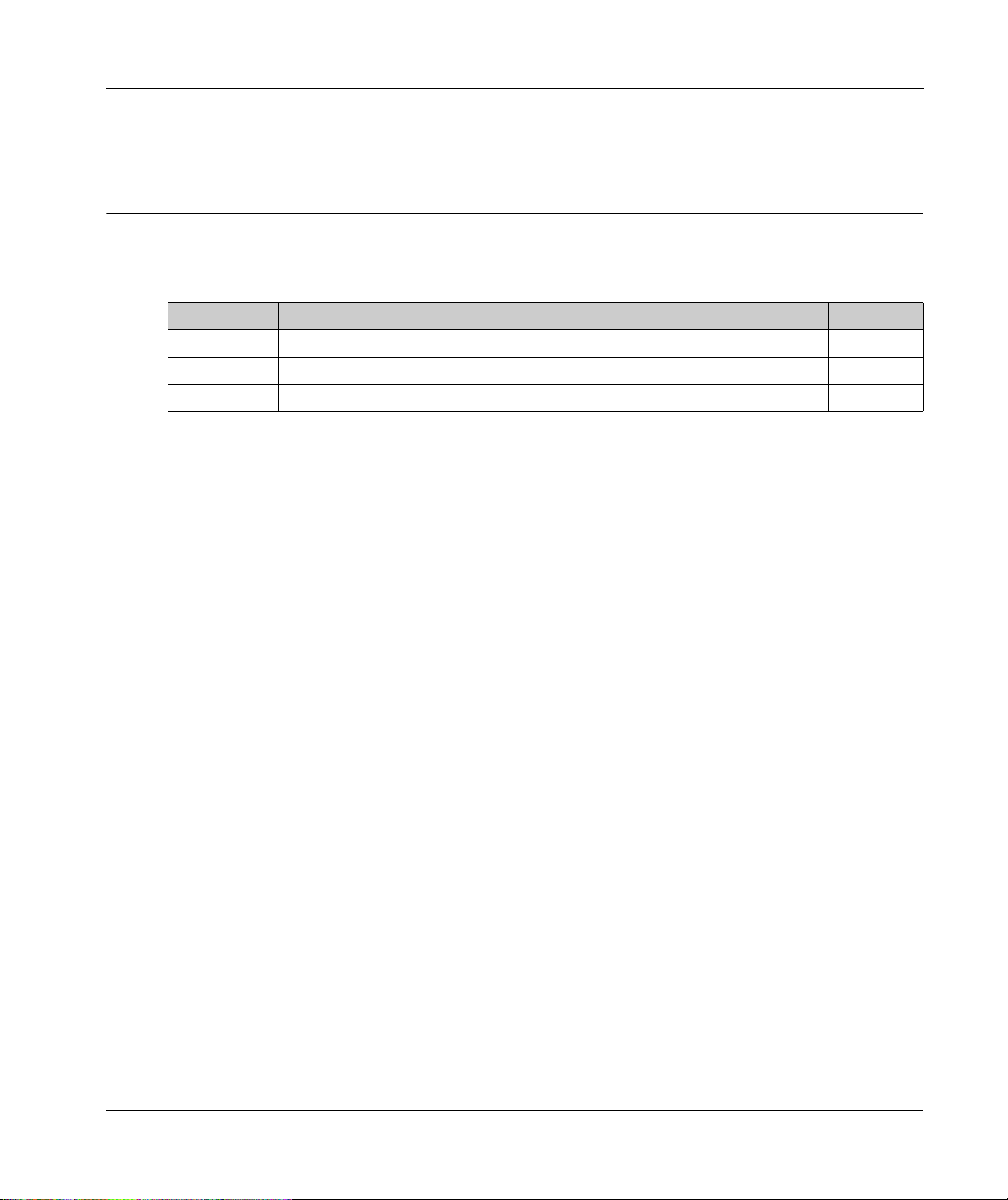
What Is in This Part?
This part contains the following chapters:
Chapter Chapter Name Page
1 M221 General Overview 19
2 M221 Features 53
3 M221 Installation 79
EIO0000003313 02/2020 17
Page 18

Modicon M221 Logic Controller Introduction
18
EIO0000003313 02/2020
Page 19
Modicon M221 Logic Con troller
M221 General Overview
EIO0000003313 02/2020
M221 General Overview
Chapter 1
M221 General Overview
Overview
This chapter provides general information about the M221 Logic Controller system architecture
and its components.
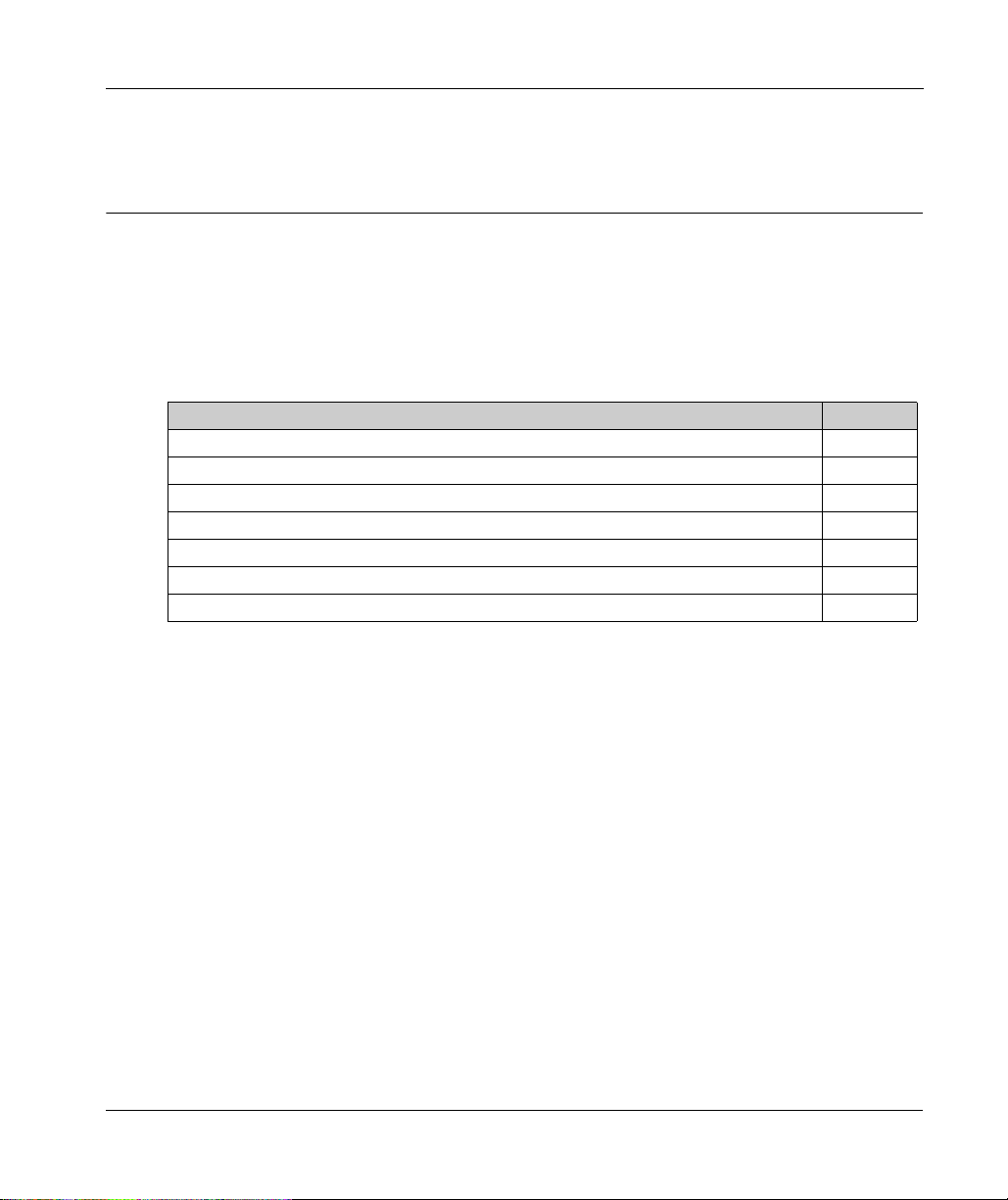
What Is in This Chapter?
This chapter contains the following topics:
TM221C Logic Controller Description 20
TM221M Logic Controller Description 25
Maximum Hardware Configuration 30
TMC2 Cartridges 34
TM3 Expansion Modules 36
TM2 Expansion Modules 45
Accessories 49
Topic Page
EIO0000003313 02/2020 19
Page 20

M221 General Overview
TM221C Logic Controller Description
Overview
The TM221C Logic Controller has various powerful features and can service a wide range of
applications.
Software configuration, programming, and commissioning are accomplished with the EcoStruxure
Machine Expert - Basic software described in the EcoStruxure Machine Expert - Basic Operating
(see EcoStruxure Machine Expert - Basic, Operating Guide)
Guide
- Programming Guide
Programming Languages
The M221 Logic Controller is configured and programmed with the EcoStruxure Machine Expert Basic software, which supports the following IEC 61131-3 programming languages:
IL: Instruction List
LD: Ladder Diagram
Grafcet (List)
Grafcet (SFC)
Power Supply
The power supply of the TM221C Logic Controller is 24 Vdc
(see page 119)
(see Modicon M221, Logic Controller, Programming Guide)
.
and the M221 Logic Controller
.
(see page 114)
or 100...240 Vac
Real Time Clock
The M221 Logic Controller includes a Real Time Clock (RTC) system
Run/Stop
The M221 Logic Controller can be operated externally by the following:
a hardware Run/Stop switch
a Run/Stop
configuration (for more information, refer to Configuring Digital Inputs
Logic Controller, Programming Guide)
EcoStruxure Machine Expert - Basic software (for more information, refer to Toolbar
(see EcoStruxure Machine Expert - Basic, Operating Guide)
a TMH2GDB Remote Graphic Display (for more information, refer to Controller State Menu
(see Modicon TMH2GDB, Remote Graphic Display, User Guide)
20
(see page 69)
(see page 54)
.
(seepage69)
operation by a dedicated digital input, defined in the software
(see Modicon M221,
.)
).
).
EIO0000003313 02/2020
Page 21

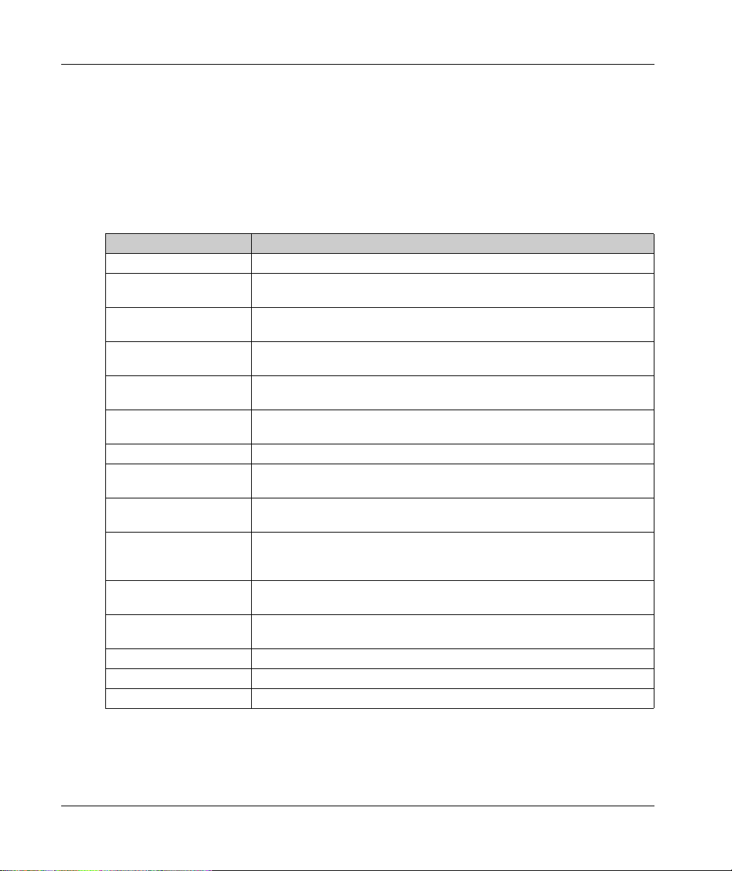
Memory
This table describes the different types of memory:
Memory Type Size Used to
RAM 512 Kbytes of RAM memory: 256 Kbytes for
Non-volatile 1.5 Mbytes, of which 256 Kbytes is used to
Embedded Inputs/Outputs
The following embedded I/O types are available, depending on the controller reference:
Regular inputs
Fast inputs associated with counters
Regular sink/source transistor outputs
Fast sink/source transistor outputs associated with pulse generators
Relay outputs
Analog inputs
Removable Storage
The M221 Logic Controllers include an embedded SD card slot
The Modicon M221 Logic Controller allows the following types of file management with an SD card:
Clone management
application, firmware, and post configuration (if it exists) of the logic controller
Firmware management
firmware to the logic controller, to a TMH2GDB Remote Graphic Display , or to TM3 expansion
modules
Application management
and restore the logic controller application, or copy it to another logic controller of the same
reference
Post configuration management
add, change, or delete the post configuration file of the logic controller
Error log management
delete the error log file of the logic controller
Memory management: back up and restore memory bits and words from a controller
internal variables and 256 Kbytes for
execute the application and contain data
application and data.
save the application
back up the application and data in case of
power outage.
(see page 72)
(see Modicon M221, Logic Controller, Programming Guide)
(see Modicon M221, Logic Controller, Programming Guide)
(see Modicon M221, Logic Controller, Programming Guide)
(see Modicon M221, Logic Controller, Programming Guide)
(see Modicon M221, Logic Controller, Programming Guide)
M221 General Overview
.
: back up the
: download
: back up
:
: back up or
Embedded Communication Features
The following types of communication ports are available depending on the controller reference:
Ethernet
USB Mini-B
Serial Line 1
EIO0000003313 02/2020 21
(seepage386)
(see page 384)
(see page 389)
Page 22

M221 General Overview
Remote Graphic Display
For more information, refer to the Modicon TMH2GDB Remote Graphic Display - User Guide.
TM221C Logic Controller
Reference Digital Inputs Digital Outputs Analog
Inputs
TM221C16R
(see page 129)
TM221CE16R
5 regular inputs
4 fast inputs
(2)
(HSC)
(1)
7 relay outputs Yes 1 serial line port
Yes 1 serial line port
(see page 135)
Communication
Ports
1 USB programming
port
1 USB programming
Power Supply
100...240 Vac
port
1 Ethernet port
TM221C16T
(see page 139)
TM221CE16T
(see page 143)
5 regular inputs
4 fast inputs
(2)
(HSC)
(1)
Source outputs
5 regular transistor outputs
2 fast outputs
(PLS/PWM/PTO/FREQGEN)
Yes 1 serial line port
1 USB programming
port
(3)
Yes 1 serial line port
1 USB programming
24 Vdc
port
1 Ethernet port
TM221C16U
(see page 147)
TM221CE16U
(see page 151)
5 regular inputs
4 fast inputs
(2)
(HSC)
(1)
Sink outputs
5 regular transistor outputs
2 fast outputs
(PLS/PWM/PTO/FREQGEN)
Yes 1 serial line port
1 USB programming
port
(3)
1 serial line port
1 USB programming
24 Vdc
port
1 Ethernet port
NOTE: The TM221C Logic Controller uses removable screw terminal blocks.
(1) The regular inputs have a maximum frequency of 5 kHz.
(2) The fast inputs can be used either as regular inputs or as fast inputs for counting or event functions.
(3) The fast transistor outputs can be used either as regular transistor outputs, for PLS, PWM, PTO, or FREQGEN
functions, or reflex outputs for HSC.
22
EIO0000003313 02/2020
Page 23

M221 General Overview
Reference Digital Inputs Digital Outputs Analog
Inputs
TM221C24R
(see page 157)
10 regular
(1)
inputs
10 relay outputs Yes 1 serial line port
4 fast inputs
TM221CE24R
(HSC)
Yes 1 serial line port
(2)
(see page 161)
Communication
Ports
1 USB programming
port
1 USB programming
Power Supply
100...240 Vac
port
1 Ethernet port
TM221C24T
(see page 165)
TM221CE24T
(see page 169)
Source outputs
8 regular transistor outputs
2 fast outputs
(PLS/PWM/PTO/FREQGEN)
Yes 1 serial line port
1 USB programming
port
(3)
Yes 1 serial line port
1 USB programming
24 Vdc
port
1 Ethernet port
TM221C24U
(see page 173)
TM221CE24U
(see page 179)
10 regular
inputs
4 fast inputs
(HSC)
(1)
8 regular transistor outputs
2 fast outputs
Sink outputs
(2)
(PLS/PWM/PTO/FREQGEN)
Yes 1 serial line port
1 USB programming
port
(3)
Yes 1 serial line port
1 USB programming
24 Vdc
port
1 Ethernet port
TM221C40R
(see page 185)
TM221CE40R
(see page 191)
20 regular
inputs
4 fast inputs
(HSC)
(1)
1 USB programming
port
16 relay outputs Yes 1 serial line port
(2)
Yes 1 serial line port
1 USB programming
100...240 Vac
port
1 Ethernet port
TM221C40T
(see page 197)
TM221CE40T
(see page 203)
Source outputs
14 regular transistor outputs
2 fast outputs
(PLS/PWM/PTO/FREQGEN)
Yes 1 serial line port
1 USB programming
port
(3)
Yes 1 serial line port
1 USB programming
24 Vdc
port
1 Ethernet port
NOTE: The TM221C Logic Controller uses removable screw terminal blocks.
(1) The regular inputs have a maximum frequency of 5 kHz.
(2) The fast inputs can be used either as regular inputs or as fast inputs for counting or event functions.
(3) The fast transistor outputs can be used either as regular transistor outputs, for PLS, PWM, PTO, or FREQGEN
functions, or reflex outputs for HSC.
EIO0000003313 02/2020 23
Page 24
M221 General Overview
Reference Digital Inputs Digital Outputs Analog
Inputs
TM221C40U
(see page 209)
TM221CE40U
20 regular
inputs
4 fast inputs
(HSC)
(1)
12 regular transistor outputs
Sink outputs
Yes 1 serial line port
4 fast outputs
(2)
(PLS/PWM/PTO/FREQGEN)
(3)
Yes 1 serial line port
(see page 215)
Communication
Ports
1 USB programming
port
1 USB programming
Power Supply
24 Vdc
port
1 Ethernet port
NOTE: The TM221C Logic Controller uses removable screw terminal blocks.
(1) The regular inputs have a maximum frequency of 5 kHz.
(2) The fast inputs can be used either as regular inputs or as fast inputs for counting or event functions.
(3) The fast transistor outputs can be used either as regular transistor outputs, for PLS, PWM, PTO, or FREQGEN
functions, or reflex outputs for HSC.
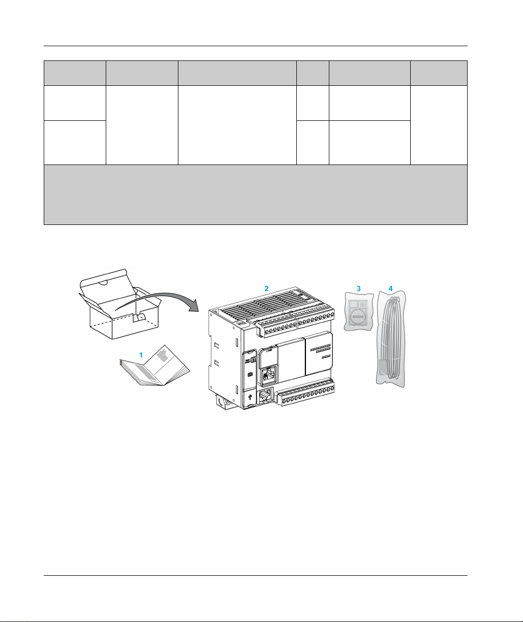
Delivery Content
The following figure presents the content of the delivery for a TM221C Logic Controller:
24
1 TM221C Logic Controller Instruction Sheet
2 TM221C Logic Controller
3 Battery holder with lithium carbon monofluoride battery, type Panasonic BR2032.
4 Analog cable
EIO0000003313 02/2020
Page 25

TM221M Logic Controller Description
Overview
The TM221M Logic Controller has various powerful features and can service a wide range of
applications.
Software configuration, programming, and commissioning are accomplished with the EcoStruxure
Machine Expert - Basic software described in the EcoStruxure Machine Expert - Basic Operating
(see EcoStruxure Machine Expert - Basic, Operating Guide)
Guide
- Programming Guide
Programming Languages
The M221 Logic Controller is configured and programmed with the EcoStruxure Machine Expert Basic software, which supports the following IEC 61131-3 programming languages:
IL: Instruction List
LD: Ladder Diagram
Grafcet (List)
Grafcet (SFC)
Power Supply
The power supply of the TM221M Logic Controller is 24 Vdc
(see Modicon M221, Logic Controller, Programming Guide)
M221 General Overview
and the M221 Logic Controller
.
(see page 114)
.
Real Time Clock
The M221 Logic Controller includes a Real Time Clock (RTC) system
(see page 54)
.
Run/Stop
The M221 Logic Controller can be operated externally by the following:
a hardware Run/Stop switch
a Run/Stop
(see page 69)
configuration (for more information, refer to Configuring Digital Inputs
Logic Controller, Programming Guide)
EcoStruxure Machine Expert - Basic software (for more information, refer to Toolbar
(see EcoStruxure Machine Expert - Basic, Operating Guide)
a TMH2GDB Remote Graphic Display (for more information, refer to Controller State Menu
(see Modicon TMH2GDB, Remote Graphic Display, User Guide)
EIO0000003313 02/2020 25
(seepage69)
operation by a dedicated digital input, defined in the software
(see Modicon M221,
)
).
).
Page 26
M221 General Overview
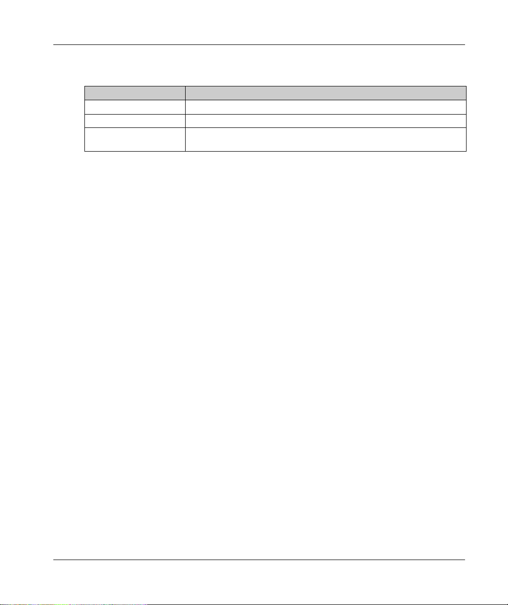
Memory
This table describes the different types of memory:
Memory Type Size Used to
RAM 512 Kbytes of RAM memory: 256 Kbytes for internal
Non-volatile 1.5 Mbytes, of which 256 Kbytes is used to back up the
Embedded Inputs/Outputs
The following embedded I/O types are available, depending on the controller reference:
Regular inputs
Fast inputs (HSC)
Regular transistor outputs
Fast transistor outputs (PLS/PWM/PTO/FREQGEN)
Relay outputs
Analog inputs
Removable Storage
The M221 Logic Controllers include an embedded SD card slot
The Modicon M221 Logic Controller allows the following types of file management with an SD card:
Clone management
application, firmware, and post configuration (if it exists) of the logic controller
Firmware management
firmware updates directly to the logic controller, and download firmware to a TMH2GDB Remote
Graphic Display
Application management
and restore the logic controller application, or copy it to another logic controller of the same
reference
Post configuration management
add, change, or delete the post configuration file of the logic controller
Error log management
delete the error log file of the logic controller
Memory management: backup/restore of memory bits and words from a controller
variables and 256 Kbytes for application and data.
application and data in case of power outage.
(see page 72)
(see Modicon M221, Logic Controller, Programming Guide)
(see Modicon M221, Logic Controller, Programming Guide)
(see Modicon M221, Logic Controller, Programming Guide)
(see Modicon M221, Logic Controller, Programming Guide)
(see Modicon M221, Logic Controller, Programming Guide)
execute the application and
contains data
save the application
.
: back up the
: download
: back up
:
: back up or
26
EIO0000003313 02/2020
Page 27

Embedded Communication Features
The following communication ports are available on the front panel of the controller, depending on
the controller reference:
Ethernet
USB Mini-B
SD Card
Serial Line 1
Serial Line 2
(seepage386)
(see page 384)
(see page 72)
(see page 389)
(see page 393)
Remote Graphic Display
For more information, refer to the Modicon TMH2GDB Remote Graphic Display - User Guide.
TM221M Logic Controller
M221 General Overview
Reference Digital Input Digital Output Analog
Communication Ports Terminal Type
Input
TM221M16R
(see page 263)
4 regular
(1)
inputs
8 relay outputs Yes 2 serial line ports
1 USB programming port
Removable screw
terminal blocks
4 fast inputs
(2)
(HSC)
TM221M16RG
(see page 263)
4 regular
(1)
inputs
8 relay outputs Yes 2 serial line ports
1 USB programming port
Removable spring
terminal blocks
4 fast inputs
(2)
(HSC)
TM221ME16R
(see page 281)
TM221ME16RG
(see page 281)
4 regular
(1)
inputs
4 fast inputs
(2)
(HSC)
4 regular
(1)
inputs
4 fast inputs
(2)
(HSC)
8 relay outputs Yes 1 serial line port
1 USB programming port
1 Ethernet port
8 relay outputs Yes 1 serial line port
1 USB programming port
1 Ethernet port
NOTE: The TM221M Logic Controller uses a 24 Vdc power supply
(see page 114)
Removable screw
terminal blocks
Removable spring
terminal blocks
.
(1) The regular inputs I2, I3, I4, and I5 have a maximum frequency of 5 kHz.
The other regular inputs have a maximum frequency of 100 Hz.
(2) The fast inputs can be used either as regular inputs or as fast inputs for counting or event functions.
(3) The fast transistor outputs can be used as regular transistor outputs, for PLS, PWM, PTO or FREQGEN
functions, or reflex outputs for HSC.
EIO0000003313 02/2020 27
Page 28

M221 General Overview
Reference Digital Input Digital Output Analog
Communication Ports Terminal Type
Input
TM221M16T
(see page 299)
4 regular
(1)
inputs
4 fast inputs
(2)
(HSC)
6 regular
transistor
outputs
2 fast transistor
outputs
Yes 2 serial line ports
1 USB programming port
Removable screw
terminal blocks
(PLS/PWM/PTO
(3)
Yes 2 serial line ports
1 USB programming port
Removable spring
terminal blocks
TM221M16TG
(see page 299)
4 regular
inputs
4 fast inputs
(HSC)
/FREQGEN)
6 regular
(1)
transistor
outputs
(2)
2 fast transistor
outputs
(PLS/PWM/PTO
(3)
Yes 1 serial line port
1 USB programming port
1 Ethernet port
Removable screw
terminal blocks
TM221ME16T
(see page 319)
4 regular
inputs
4 fast inputs
(HSC)
/FREQGEN)
6 regular
(1)
transistor
outputs
(2)
2 fast transistor
outputs
(PLS/PWM/PTO
(3)
Yes 1 serial line port
USB programming port
1 Ethernet port
Removable spring
terminal blocks
TM221ME16TG
(see page 319)
4 regular
(1)
inputs
4 fast inputs
(2)
(HSC)
/FREQGEN)
6 regular
transistor
outputs
2 fast transistor
outputs
(PLS/PWM/PTO
/FREQGEN)
TM221M32TK
(see page 341)
12 regular
inputs
4 fast inputs
(HSC)
(1)
transistor
outputs
14 regular
(2)
2 fast outputs
(PLS/PWM/PTO
/FREQGEN)
NOTE: The TM221M Logic Controller uses a 24 Vdc power supply
(3)
Yes 2 serial line ports
1 USB programming port
(3)
(see page 114)
HE10 (MIL 20)
connectors
.
(1) The regular inputs I2, I3, I4, and I5 have a maximum frequency of 5 kHz.
The other regular inputs have a maximum frequency of 100 Hz.
(2) The fast inputs can be used either as regular inputs or as fast inputs for counting or event functions.
(3) The fast transistor outputs can be used as regular transistor outputs, for PLS, PWM, PTO or FREQGEN
functions, or reflex outputs for HSC.
28
EIO0000003313 02/2020
Page 29
M221 General Overview
Reference Digital Input Digital Output Analog
TM221ME32TK
(see page 341)
NOTE: The TM221M Logic Controller uses a 24 Vdc power supply
(1) The regular inputs I2, I3, I4, and I5 have a maximum frequency of 5 kHz.
The other regular inputs have a maximum frequency of 100 Hz.
(2) The fast inputs can be used either as regular inputs or as fast inputs for counting or event functions.
(3) The fast transistor outputs can be used as regular transistor outputs, for PLS, PWM, PTO or FREQGEN
functions, or reflex outputs for HSC.
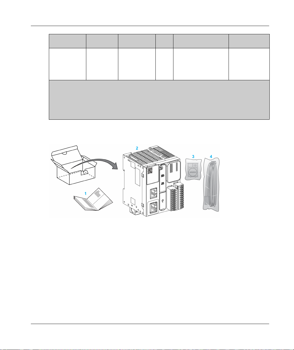
Delivery Content
The following figure presents the content of the delivery for a TM221M Logic Controller:
12 regular
inputs
4 fast inputs
(HSC)
Communication Ports Terminal Type
Input
(1)
outputs
2 fast outputs
14 regular
(2)
(PLS/PWM/PTO
/FREQGEN)
Yes 1 serial line port
1 USB programming port
1 Ethernet port
(3)
(see page 114)
HE10 (MIL 20)
connectors
.
1 TM221M Logic Controller Instruction Sheet
2 TM221M Logic Controller
3 Battery holder with lithium carbon monofluoride battery, type Panasonic BR2032.
4 Analog cable
EIO0000003313 02/2020 29
Page 30
M221 General Overview
Maximum Hardware Configuration
Introduction
The M221 Logic Controller is a control system that offers an all-in-one solution with optimized
configurations and an expandable architecture.
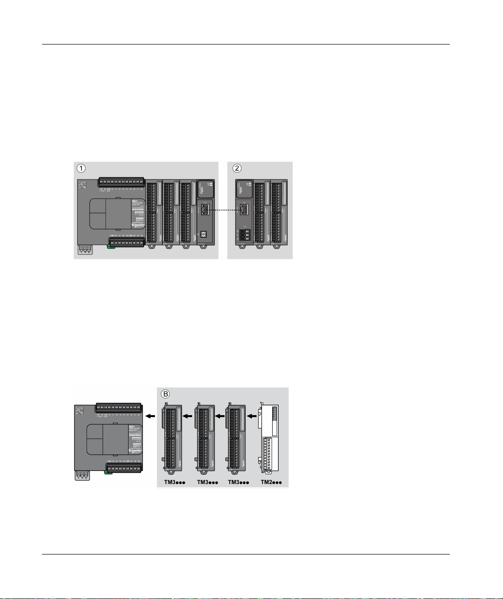
Local and Remote Configuration Principle
The following figure defines the local and remote configurations:
(1) Local configuration
(2) Remote configuration
M221 Logic Controller Local Configuration Architecture
Optimized local configuration and flexibility are provided by the association of:
M221 Logic Controller
TM3 expansion modules
TM2 expansion modules
Application requirements determine the architecture of your M221 Logic Controller configuration.
The following figure represents the components of a local configuration:
30
(B) Expansion modules (see maximum number of modules)
EIO0000003313 02/2020
Page 31

NOTE: You cannot mount a TM2 module before any TM3 module as indicated in the following
figure:
M221 Logic Controller Remote Configuration Architecture
Optimized remote configuration and flexibility are provided by the association of:
M221 Logic Controller
TM3 expansion modules
TM3 transmitter and receiver modules
Application requirements determine the architecture of your M221 Logic Controller configuration.
NOTE: You cannot use TM2 modules in configurations that include the TM3 transmitter and
receiver modules.
The following figure represents the components of a remote configuration:
M221 General Overview
(1) Logic controller and modules
(C) Expansion modules (7 maximum)
EIO0000003313 02/2020 31
Page 32

M221 General Overview
Maximum Number of Modules
The following table shows the maximum configuration supported:
References Maximum Type of Configuration
TM221C16•
TM221CE16•
TM221C24•
TM221CE24•
TM221C40•
TM221CE40•
TM221M16R•
TM221ME16R•
TM221M16T•
TM221ME16T•
TM221M32TK
TM221ME32TK
TM3XREC1 7 TM3 expansion modules Remote
NOTE: TM3 transmitter and receiver modules are not included in a count of the maximum number of
expansion modules.
NOTE: The configuration with its TM3 and TM2 expansion modules is validated by EcoStruxure
Machine Expert - Basic software in the Configuration window taking into account the total power
consumption of the installed modules.
NOTE: In some environments, the maximum configuration populated by high consumption
modules, coupled with the maximum distance allowable between the TM3 transmitter and receiver
modules, may present bus communication issues although the EcoStruxure Machine Expert Basic software allows for the configuration. In such a case you will need to analyze the
consumption of the modules chosen for your configuration, as well as the minimum cable distance
required by your application, and possibly seek to optimize your choices.
7 TM3 / TM2 expansion modules Local
32
EIO0000003313 02/2020
Page 33

Current Supplied to the I/O Bus
The following table shows the maximum current supplied by the controllers to the I/O Bus:
Reference IO Bus 5 Vdc IO Bus 24 Vdc
TM221C16R
TM221CE16R
TM221C16T
TM221CE16T
TM221C16U
TM221CE16U
TM221C24R
TM221CE24R
TM221C24T
TM221CE24T
TM221C24U
TM221CE24U
TM221C40R
TM221CE40R
TM221C40T
TM221CE40T
TM221C40U
TM221CE40U
TM221M16R•
TM221ME16R•
TM221M16T•
TM221ME16T•
TM221M32TK
TM221ME32TK
M221 General Overview
325 mA 120 mA
325 mA 148 mA
325 mA 148 mA
520 mA 160 mA
520 mA 200 mA
520 mA 200 mA
520 mA 240 mA
520 mA 304 mA
520 mA 304 mA
520 mA 460 mA
520 mA 492 mA
520 mA 484 mA
NOTE: Expansion modules consume current from the 5 Vdc and 24 Vdc supplied to the I/O Bus.
Therefore, the current delivered by the logic controller to the I/O Bus defines the maximum number
of expansion modules that can be connected to the I/O Bus (validated by EcoStruxure Machine
Expert - Basic software in the Configuration window).
EIO0000003313 02/2020 33
Page 34

M221 General Overview
TMC2 Cartridges
Overview
You can expand the number of I/Os or communication options of your Modicon TM221C Logic
Controller by adding TMC2 cartridges.
For more information, refer to the TMC2 Cartridges Hardware Guide.
TMC2 Standard Cartridges
The following table presents the general-purpose TMC2 cartridges with the corresponding channel
type, voltage/current range, and terminal type:
Reference Channels Channel Type Voltage
Current
TMC2AI2 2 Analog inputs
(voltage or current)
TMC2TI2 2 Analog temperature
inputs
TMC2AQ2V 2 Analog voltage
outputs
TMC2AQ2C 2 Analog current
outputs
(1)
TMC2SL1
(1) Only one serial line cartridge (TMC2SL1, TMC2CONV01) may be added to a logic controller.
1 Serial line RS232 or RS485 3.81 mm (0.15 in.)
0...10 Vdc
0...20 mA or 4...20 mA
Thermocouple type K, J,
R, S, B, E, T, N,C
3 wires RTD type Pt100,
Pt1000, Ni100, Ni1000
0...10 Vdc 3.81 mm (0.15 in.)
4...20 mA 3.81 mm (0.15 in.)
Terminal Type
3.81 mm (0.15 in.)
pitch, non-removable
screw terminal block
3.81 mm (0.15 in.)
pitch, non-removable
screw terminal block
pitch, non-removable
screw terminal block
pitch, non-removable
screw terminal block
pitch, non-removable
screw terminal block
34
EIO0000003313 02/2020
Page 35

TMC2 Application Cartridges
The following table presents the applicative TMC2 cartridges with the corresponding channel type,
voltage/current range, and terminal type:
M221 General Overview
Reference Channels Channel Type Voltage
Terminal Type
Current
TMC2HOIS01 2 Analog inputs
(voltage or current)
0...10 Vdc
0...20 mA or 4...20 mA
3.81 mm (0.15 in.)
pitch, non-removable
screw terminal block
TMC2PACK01 2 Analog inputs
(voltage or current)
0...10 Vdc
0...20 mA or 4...20 mA
3.81 mm (0.15 in.)
pitch, non-removable
screw terminal block
(1)
TMC2CONV01
1 Serial line RS232 or RS485 3.81 mm (0.15 in.)
pitch, non-removable
screw terminal block
(1) Only one serial line cartridge (TMC2SL1, TMC2CONV01) may be added to a logic controller.
EIO0000003313 02/2020 35
Page 36

M221 General Overview
TM3 Expansion Modules
Introduction
The range of TM3 expansion modules includes:
Digital modules, classified as follows:
Input modules
Output modules
Mixed input/output modules
Analog modules, classified as follows:
Input modules
Output modules
Mixed input/output modules
Expert modules
Safety modules
Transmitter and Receiver modules
For more information, refer to the following documents:
TM3 Digital I/O Modules Hardware Guide
TM3 Analog I/O Modules Hardware Guide
TM3 Expert I/O Modules Hardware Guide
TM3 Safety Modules Hardware Guide
TM3 Transmitter and Receiver Modules Hardware Guide
(see page 37)
(see page 40)
(see page 42)
(see page 43)
(see page 37)
(see page 39)
(see page 41)
(see page 42)
(seepage44)
36
EIO0000003313 02/2020
Page 37

TM3 Digital Input Modules
The following table shows the TM3 digital input expansion modules, with corresponding channel
type, nominal voltage/current, and terminal type:
M221 General Overview
Reference Channels Channel Type Voltage
TM3DI8A 8 Regular inputs 120 Vac
TM3DI8 8 Regular inputs 24 Vdc
TM3DI8G 8 Regular inputs 24 Vdc
TM3DI16 16 Regular inputs 24 Vdc
TM3DI16G 16 Regular inputs 24 Vdc
TM3DI16K 16 Regular inputs 24 Vdc
TM3DI32K 32 Regular inputs 24 Vdc
TM3 Digital Output Modules
The following table shows the TM3 digital output expansion modules, with corresponding channel
type, nominal voltage/current, and terminal type:
Reference Channels Channel Type Voltage
TM3DQ8R 8 Relay outputs 24 Vdc / 240 Vac
TM3DQ8RG 8 Relay outputs 24 Vdc / 240 Vac
TM3DQ8T 8 Regular transistor
TM3DQ8TG 8 Regular transistor
TM3DQ8U 8 Regular transistor
outputs (source)
outputs (source)
outputs (sink)
Terminal Type / Pitch
Current
Removable screw terminal block / 5.08 mm
7.5 mA
Removable screw terminal block / 5.08 mm
7mA
Removable spring terminal block / 5.08 mm
7mA
Removable screw terminal blocks / 3.81 mm
7mA
Removable spring terminal blocks / 3.81 mm
7mA
HE10 (MIL 20) connector
5mA
HE10 (MIL 20) connector
5mA
Current
7 A maximum per common line /
2 A maximum per output
7 A maximum per common line /
2 A maximum per output
24 Vdc
4 A maximum per common
line/0.5 A maximum per output
24 Vdc
4 A maximum per common
line/0.5 A maximum per output
24 Vdc
4 A maximum per common
line/0.5 A maximum per output
Terminal Type / Pitch
Removable screw
terminal block /
5.08 mm
Removable spring
terminal block /
5.08 mm
Removable screw
terminal block /
5.08 mm
Removable spring
terminal block /
5.08 mm
Removable screw
terminal block /
5.08 mm
EIO0000003313 02/2020 37
Page 38

M221 General Overview
Reference Channels Channel Type Voltage
Current
TM3DQ8UG 8 Regular transistor
outputs (sink)
24 Vdc
4 A maximum per common
line/0.5 A maximum per output
TM3DQ16R 16 Relay outputs 24 Vdc / 240 Vac
8 A maximum per common line /
2 A maximum per output
TM3DQ16RG 16 Relay outputs 24 Vdc / 240 Vac
8 A maximum per common line /
2 A maximum per output
TM3DQ16T 16 Regular transistor
outputs (source)
24 Vdc
8 A maximum per common line /
0.5 A maximum per output
TM3DQ16TG 16 Regular transistor
outputs (source)
24 Vdc
8 A maximum per common line /
0.5 A maximum per output
TM3DQ16U 16 Regular transistor
outputs (sink)
24 Vdc
8 A maximum per common line /
0.5 A maximum per output
TM3DQ16UG 16 Regular transistor
outputs (sink)
24 Vdc
8 A maximum per common line /
0.5 A maximum per output
TM3DQ16TK 16 Regular transistor
outputs (source)
24 Vdc
2 A maximum per common line /
0.1 A maximum per output
TM3DQ16UK 16 Regular transistor
outputs (sink)
24 Vdc
2 A maximum per common line /
0.1 A maximum per output
TM3DQ32TK 32 Regular transistor
outputs (source)
24 Vdc
2 A maximum per common line /
0.1 A maximum per output
TM3DQ32UK 32 Regular transistor
outputs (sink)
24 Vdc
2 A maximum per common line /
0.1 A maximum per output
Terminal Type / Pitch
Removable spring
terminal block /
5.08 mm
Removable screw
terminal blocks /
3.81 mm
Removable spring
terminal blocks /
3.81 mm
Removable screw
terminal blocks /
3.81 mm
Removable spring
terminal blocks /
3.81 mm
Removable screw
terminal blocks /
3.81 mm
Removable spring
terminal blocks /
3.81 mm
HE10 (MIL 20)
connector
HE10 (MIL 20)
connector
HE10 (MIL 20)
connectors
HE10 (MIL 20)
connectors
38
EIO0000003313 02/2020
Page 39

TM3 Digital Mixed Input/Output Modules
This following table shows the TM3 mixed I/O modules, with corresponding channel type, nominal
voltage/current, and terminal type:
M221 General Overview
Reference Channels Channel Type Voltage
Current
TM3DM8R 4 Regular inputs 24 Vdc
7mA
4 Relay outputs 24 Vdc / 240 Vac
7 A maximum per common line / 2 A
maximum per output
TM3DM8RG 4 Regular inputs 24 Vdc
7mA
4 Relay outputs 24 Vdc / 240 Vac
7 A maximum per common line / 2 A
maximum per output
TM3DM24R 16 Regular inputs 24 Vdc
7mA
8 Relay outputs 24 Vdc / 240 Vac
7 A maximum per common line / 2 A
maximum per output
TM3DM24RG 16 Regular inputs 24 Vdc
7mA
8 Relay outputs 24 Vdc / 240 Vac
7 A maximum per common line / 2 A
maximum per output
Terminal Type / Pitch
Removable screw
terminal block /
5.08 mm
Removable spring
terminal block /5.08 mm
Removable screw
terminal
blocks / 3.81 mm
Removable spring
terminal
blocks / 3.81 mm
EIO0000003313 02/2020 39
Page 40

M221 General Overview
TM3 Analog Input Modules
The following table shows the TM3 analog input expansion modules, with corresponding
resolution, channel type, nominal voltage/current, and terminal type:
Reference Resolution Channels Channel
Type
TM3AI2H 16 bit, or
15 bit + sign
TM3AI2HG 16 bit, or
15 bit + sign
TM3AI4 12 bit, or
11 bit + sign
TM3AI4G 12 bit, or
11 bit + sign
TM3AI8 12 bit, or
11 bit + sign
TM3AI8G 12 bit, or
11 bit + sign
TM3TI4 16 bit, or
15 bit + sign
2 inputs 0...10 Vdc
2 inputs 0...10 Vdc
4 inputs 0...10 Vdc
4 inputs 0...10 Vdc
8 inputs 0...10 Vdc
8 inputs 0...10 Vdc
4 inputs 0...10 Vdc
Mode Terminal Type / Pitch
Removable screw terminal block /
-10…+10 Vdc
0...20 mA
4...20 mA
-10…+10 Vdc
0...20 mA
4...20 mA
-10…+10 Vdc
0...20 mA
4...20 mA
-10…+10 Vdc
0...20 mA
4...20 mA
-10…+10 Vdc
0...20 mA
4...20 mA
0...20 mA
extended
4...20 mA
extended
-10…+10 Vdc
0...20 mA
4...20 mA
0...20 mA
extended
4...20 mA
extended
-10…+10 Vdc
0...20 mA
4...20 mA
Thermocouple
PT100/1000
NI100/1000
5.08 mm
Removable spring terminal block /
5.08 mm
Removable screw terminal block /
3.81 mm
Removable spring terminal blocks
/ 3.81 mm
Removable screw terminal block /
3.81 mm
Removable spring terminal blocks
/ 3.81 mm
Removable screw terminal block /
3.81 mm
40
EIO0000003313 02/2020
Page 41

M221 General Overview
Reference Resolution Channels Channel
TM3TI4G 16 bit, or
15 bit + sign
TM3TI4D 16 bit, or
15 bit + sign
TM3TI4DG 16 bit, or
15 bit + sign
TM3TI8T 16 bit, or
15 bit + sign
TM3TI8TG 16 bit, or
15 bit + sign
TM3 Analog Output Modules
The following table shows the TM3 analog output modules, with corresponding resolution, channel
type, nominal voltage/current, and terminal type:
Reference Resolution Channels Channel
TM3AQ2 12 bit, or
11 bit + sign
TM3AQ2G 12 bit, or
11 bit + sign
TM3AQ4 12 bit, or
11 bit + sign
TM3AQ4G 12 bit, or
11 bit + sign
Mode Terminal Type / Pitch
Type
4 inputs 0...10 Vdc
-10…+10 Vdc
0...20 mA
4...20 mA
Thermocouple
PT100/1000
NI100/1000
4 inputs Thermocouple Removable screw terminal block /
4 inputs Thermocouple Removable spring terminal blocks
8 inputs Thermocouple
NTC/PTC
Ohmmeter
8 inputs Thermocouple
NTC/PTC
Ohmmeter
Mode Terminal Type / Pitch
Type
2 outputs 0...10 Vdc
-10…+10 Vdc
0...20 mA
4...20 mA
2 outputs 0...10 Vdc
-10…+10 Vdc
0...20 mA
4...20 mA
4 outputs 0...10 Vdc
-10…+10 Vdc
0...20 mA
4...20 mA
4 outputs 0...10 Vdc
-10…+10 Vdc
0...20 mA
4...20 mA
Removable spring terminal blocks
/ 3.81 mm
3.81 mm
/ 3.81 mm
Removable screw terminal block /
3.81 mm
Removable spring terminal blocks
/ 3.81 mm
Removable screw
terminal block /
5.08 mm
Removable spring
terminal block /
5.08 mm
Removable screw
terminal block /
5.08 mm
Removable spring
terminal block /
5.08 mm
EIO0000003313 02/2020 41
Page 42

M221 General Overview
TM3 Analog Mixed Input/Output Modules
This following table shows the TM3 analog mixed I/O modules, with corresponding resolution,
channel type, nominal voltage/current, and terminal type:
Reference Resolution Channels Channel
Type
TM3AM6 12 bit, or
11 bit + sign
TM3AM6G 12 bit, or
11 bit + sign
TM3TM3 16 bit, or
15 bit + sign
12 bit, or
11 bit + sign
TM3TM3G 16 bit, or
15 bit + sign
12 bit, or
11 bit + sign
4 inputs 0...10 Vdc
2 outputs
4 inputs 0...10 Vdc
2 outputs
2 inputs 0...10 Vdc
1 outputs 0...10 Vdc
2 inputs 0...10 Vdc
1 outputs 0...10 Vdc
Mode Terminal Type / Pitch
Removable screw
-10...+10 Vdc
0...20 mA
4...20 mA
-10...+10 Vdc
0...20 mA
4...20 mA
-10...+10 Vdc
0...20 mA
4...20 mA
Thermocouple
PT100/1000
NI100/1000
-10...+10 Vdc
0...20 mA
4...20 mA
-10...+10 Vdc
0...20 mA
4...20 mA
Thermocouple
PT100/1000
NI100/1000
-10...+10 Vdc
0...20 mA
4...20 mA
terminal block /
3.81 mm
Removable spring
terminal block /
3.81 mm
Removable screw
terminal block /
5.08 mm
Removable spring
terminal block /
5.08 mm
TM3 Expert Module
The following table shows the TM3 expert expansion module, with corresponding terminal types:
Reference Description Terminal Type / Pitch
TM3XTYS4 TeSys module 4 front connectors RJ-45
42
1 removable power supply connector / 5.08 mm
EIO0000003313 02/2020
Page 43

TM3 Safety Modules
This table contains the TM3 safety modules
Guide)
, with the corresponding channel type, nominal voltage/current, and terminal type:
M221 General Overview
(see Modicon TM3, Safety Modules, Hardware
Reference Function
Category
TM3SAC5R 1 function,
up to
category 3
TM3SAC5RG 1 function,
up to
category 3
TM3SAF5R 1 function,
up to
category 4
TM3SAF5RG 1 function,
up to
category 4
TM3SAFL5R 2 functions,
up to
category 3
TM3SAFL5RG 2 functions,
up to
category 3
(1)
Depending on external wiring
(2)
Non-monitored start
Channels Channel type Voltage
Current
(1)
1 or 2
(2)
Start
3 in parallel Relay outputs
Safety input 24 Vdc
Input
100 mA maximum
24 Vdc / 230 Vac
Normally open
6 A maximum per
output
(1)
1 or 2
(2)
Start
3 in parallel Relay outputs
Safety input 24 Vdc
Input
100 mA maximum
24 Vdc / 230 Vac
Normally open
6 A maximum per
output
(1)
2
Start Input
3 in parallel Relay outputs
Safety inputs 24 Vdc
100 mA maximum
24 Vdc / 230 Vac
Normally open
6 A maximum per
output
(1)
2
Start Input
3 in parallel Relay outputs
Safety inputs 24 Vdc
100 mA maximum
24 Vdc / 230 Vac
Normally open
6 A maximum per
output
(1)
2
Start Input
3 in parallel Relay outputs
Safety inputs 24 Vdc
100 mA maximum
24 Vdc / 230 Vac
Normally open
6 A maximum per
output
(1)
2
Start Input
3 in parallel Relay outputs
Safety inputs 24 Vdc
100 mA maximum
24 Vdc / 230 Vac
Normally open
6 A maximum per
output
Terminal type
3.81 mm (0.15 in.) and
5.08 mm (0.20 in.),
removable screw
terminal block
3.81 mm (0.15 in.) and
5.08 mm (0.20 in.),
removable spring
terminal block
3.81 mm (0.15 in.) and
5.08 mm (0.20 in.),
removable screw
terminal block
3.81 mm (0.15 in.) and
5.08 mm (0.20 in.),
removable spring
terminal block
3.81 mm (0.15 in.) and
5.08 mm (0.20 in.),
removable screw
terminal block
3.81 mm (0.15 in.) and
5.08 mm (0.20 in.),
removable spring
terminal block
EIO0000003313 02/2020 43
Page 44

M221 General Overview
Reference Function
Channels Channel type Voltage
Category
TM3SAK6R 3 functions,
up to
category 4
(1)
1 or 2
Start Input
3 in parallel Relay outputs
TM3SAK6RG 3 functions,
up to
category 4
(1)
1 or 2
Start Input
3 in parallel Relay outputs
(1)
Depending on external wiring
(2)
Non-monitored start
TM3 Transmitter and Receiver Modules
The following table shows the TM3 transmitter and receiver expansion modules:
Reference Description Terminal Type / Pitch
TM3XTRA1 Data transmitter module for remote I/O 1 front connector RJ-45
TM3XREC1 Data receiver module for remote I/O 1 front connector RJ-45
Current
Safety inputs 24 Vdc
100 mA maximum
24 Vdc / 230 Vac
Normally open
6 A maximum per
output
Safety inputs 24 Vdc
100 mA maximum
24 Vdc / 230 Vac
Normally open
6 A maximum per
output
1 screw for functional ground connection
Power supply connector / 5.08 mm
Terminal type
3.81 mm (0.15 in.) and
5.08 mm (0.20 in.),
removable screw
terminal block
3.81 mm (0.15 in.) and
5.08 mm (0.20 in.),
removable spring
terminal block
44
EIO0000003313 02/2020
Page 45

TM2 Expansion Modules
Overview
You can expand the number of I/Os of your M221 Logic Controller by adding TM2 I/O expansion
modules.
The following types of electronic modules are supported:
TM2 digital I/O expansion modules
TM2 analog I/O expansion modules
For more information, refer to the following documents:
TM2 Digital I/O Expansion Modules Hardware Guide
TM2 Analog I/O Expansion Modules Hardware Guide
NOTE: TM2 modules can only be used in the local configuration, and only if there is no TM3
transmitter and receiver modules present in the configuration.
NOTE: It is prohibited to mount a TM2 module before any TM3 module. The TM2 modules must
be mounted and configured at the end of the local configuration.
TM2 Digital Input Expansion Modules
The following table shows the compatible TM2 digital input expansion modules with the
corresponding channel type, nominal voltage/current, and terminal type:
M221 General Overview
Reference Channels Channel Type Voltage
Current
TM2DAI8DT 8 Regular inputs 120 Vac
7.5 mA
TM2DDI8DT 8 Regular inputs 24 Vdc
7mA
TM2DDI16DT 16 Regular inputs 24 Vdc
7mA
TM2DDI16DK 16 Regular inputs 24 Vdc
5mA
TM2DDI32DK 32 Regular inputs 24 Vdc
5mA
EIO0000003313 02/2020 45
Terminal Type
Removable screw terminal block
Removable screw terminal block
Removable screw terminal block
HE10 (MIL 20) connector
HE10 (MIL 20) connector
Page 46

M221 General Overview
TM2 Digital Output Expansion Modules
The following table shows the compatible TM2 digital output expansion modules with the
corresponding channel type, nominal voltage/current, and terminal type:
Reference Channels Channel type Voltage
TM2DRA8RT 8 Relay outputs 30 Vdc / 240 Vac
TM2DRA16RT 16 Relay outputs 30 Vdc / 240 Vac
TM2DDO8UT 8 Regular transistor
outputs (sink)
TM2DDO8TT 8 Regular transistor
outputs (source)
TM2DDO16UK 16 Regular transistor
outputs (sink)
TM2DDO16TK 16 Regular transistor
outputs (source)
TM2DDO32UK 32 Regular transistor
outputs (sink)
TM2DDO32TK 32 Regular transistor
outputs (source)
TM2 Digital Mixed Input/Output Expansion Modules
The following table shows the compatible TM2 digital mixed I/O expansion modules with the
corresponding channel type, nominal voltage/current, and terminal type:
Reference Channels Channel type Voltage
TM2DMM8DRT 4 Regular inputs 24 Vdc
4 Relay outputs 24 Vdc / 240 Vac
TM2DMM24DRF 16 Regular inputs 24 Vdc
8 Relay outputs 24 Vdc / 240 Vac
Terminal type
Current
Removable screw terminal
2 A max
2 A max
24 Vdc
0.3 A max per output
24 Vdc
0.5 A max per output
24 Vdc
0.1 A max per output
24 Vdc
0.4 A max per output
24 Vdc
0.1 A max per output
24 Vdc
0.4 A max per output
Current
7mA
7 A maximum per common line /
2 A maximum per output
7 mA
7 A maximum per common line /
2 A maximum per output
block
Removable screw terminal
block
Removable screw terminal
block
Removable screw terminal
block
HE10 (MIL 20) connector
HE10 (MIL 20) connector
HE10 (MIL 20) connector
HE10 (MIL 20) connector
Terminal type
Removable screw
terminal block
Non-removable
spring terminal
block
46
EIO0000003313 02/2020
Page 47

TM2 Analog Input Expansion Modules
The following table shows the compatible TM2 analog input expansion modules with the
corresponding channel type, nominal voltage/current, and terminal type:
M221 General Overview
Reference Channels Channel type Voltage
TM2AMI2HT 2 High-level inputs 0...10 Vdc
TM2AMI2LT 2 Low-level inputs Thermocouple type
TM2AMI4LT 4 Analog inputs 0...10 Vdc
TM2AMI8HT 8 Analog inputs 0...20 mA
TM2ARI8HT 8 Analog inputs NTC / PTC Removable screw terminal block
TM2ARI8LRJ 8 Analog inputs PT100/1000 RJ11 connector
TM2ARI8LT 8 Analog inputs PT100/1000 Removable screw terminal block
TM2 Analog Output Expansion Modules
The following table shows the compatible TM2 analog output expansion modules with the
corresponding channel type, nominal voltage/current, and terminal type:
Reference Channels Channel type Voltage
TM2AMO1HT 1 Analog outputs 0...10 Vdc
TM2AVO2HT 2 Analog outputs +/- 10 Vdc Removable screw terminal block
Terminal Type
Current
Removable screw terminal block
4...20 mA
Removable screw terminal block
J,K,T
Removable screw terminal block
0...20 mA
PT100/1000
Ni100/1000
Removable screw terminal block
0...10 Vdc
Terminal Type
Current
Removable screw terminal block
4...20 mA
EIO0000003313 02/2020 47
Page 48

M221 General Overview
TM2 Analog Mixed Input/Output Expansion Modules
The following table shows the compatible TM2 analog mixed I/O expansion modules with the
corresponding channel type, nominal voltage/current, and terminal type:
Reference Channels Channel type Voltage
Current
TM2AMM3HT 2 Analog inputs 0...10 Vdc 4...20 mA Removable screw terminal block
1 Analog outputs 0...10 Vdc 4...20 mA
TM2AMM6HT 4 Analog inputs 0...10 Vdc 4...20 mA Removable screw terminal block
2 Analog outputs 0...10 Vdc 4...20 mA
TM2ALM3LT 2 Low-level inputs Thermo J,K,T, PT100 Removable screw terminal block
1 Analog outputs 0...10 Vdc 4...20 mA
Terminal Type
48
EIO0000003313 02/2020
Page 49

M221 General Overview
Accessories
Overview
This section describes the accessories, cables, and Telefast.
Accessories
Reference Description Use Quantity
TMASD1 SD Card
TMAT2MSET Set of 8 removable screw terminal
blocks:
4 x Removable screw terminal
4 x Removable screw terminal
TMAT2MSETG Set of 8 removable spring terminal
blocks:
4 x Removable spring terminal
4 x Removable spring terminal
TMAT2PSET Set of 5 removable screw terminal
block
AB1AB8P35 End brackets Help secure the logic controller or
TM2XMTGB Grounding Bar Connects the cable shield and the
TM200RSRCEMC Shielding take-up clip Mounts and connects the ground to the
TMAM2 Mounting Kit Mounts the controller and I/O modules
(see page 72)
blocks (pitch 3.81 mm) with 11
terminals for inputs/outputs
blocks (pitch 3.81 mm) with 10
terminals for inputs/outputs
blocks (pitch 3.81 mm) with 11
terminals for inputs/outputs
blocks (pitch 3.81 mm) with 10
terminals for inputs/outputs
Use to update the controller firmware,
store data (data logging), initialize a
controller with a new application or clone
a controller.
Connects M221 Logic Controller
embedded I/Os.
Connects M221 Logic Controller
embedded I/Os.
Connects 24 Vdc power supply. 1
receiver module and their expansion
modules on a top hat section rail (DIN
rail).
module to the functional ground.
cable shielding.
directly to a flat, vertical panel.
1
1
1
1
1
25 pack
1
EIO0000003313 02/2020 49
Page 50

M221 General Overview
Cables
Reference Description Details Length
BMXXCAUSBH018 Terminal port/USB
BMXXCAUSBH045 Terminal port/USB
TMACBL1 Analog cables Cable equipped with a connector 1 m
TCSMCN3M4F3C2 RS-232 serial link
TCSMCN3M4M3S2 RS-232 serial link
TWDFCW30K Digital I/O cables with
TWDFCW50K Cable equipped at a one end with an HE10
port cordset
port cordset
cordset
1 RJ45 connector and
1 SUB-D 9 connector
cordset
1 RJ45 connector and
1 SUB-D 9 connector
free wires for 20-pin
Modular controller
From the USB mini-B port on the TM221C Logic
Controller to USB port on the PC terminal.
1.8 m
(5.9 ft)
NOTE: Grounded and shielded, this USB
cable is suitable for long duration connections.
From the USB mini-B port on the TM221M
Logic Controller to USB port on the PC terminal.
4.5 m
(14.8 ft)
NOTE: Grounded and shielded, this USB
cable is suitable for long duration connections.
(3.28 ft)
For DTE terminal (printer) 3 m
(9.84 ft)
For DCE terminal (modem, converter) 3 m
(9.84 ft)
Cable equipped at a one end with an HE10
connector. (AWG 22 / 0.34 mm
connector. (AWG 22 / 0.34 mm
2
)
2
)
3m
(9.84 ft)
5m
(16.4 ft)
50
EIO0000003313 02/2020
Page 51

TWDFCW••K Cable Description
The following table provides specifications for the TWDFCW30K/50K with free wires for 20-pin
connectors (HE10 or MIL20):
Cable illustration Pin Connector Wire Color
M221 General Overview
1White
2Brown
3 Green
4Yellow
5Grey
6Pink
7Blue
8Red
9Black
10 Violet
11 Grey and pink
12 Red and blue
13 White and green
14 Brown and green
15 White and yellow
16 Yellow and brown
17 White and grey
18 Grey and brown
19 White and pink
20 Pink and brown
EIO0000003313 02/2020 51
Page 52

M221 General Overview
Telefast Pre-Wiring Sub-bases
The following illustration shows the Telefast system:
52
1 TM221M32TK / TM221ME32TK
2 Cable equipped with a 20-way HE 10 connector at each end.)
3 16 channel sub-base for input extension modules.
4 16 channel sub-base for output extension modules.
5 16 channel sub-base for output extension modules.
Refer to
TM221M Logic Controller Instruction Sheet
.
EIO0000003313 02/2020
Page 53

Modicon M221 Logic Con troller
M221 Features
EIO0000003313 02/2020
M221 Features
Chapter 2
M221 Features
Overview
This chapter describes the Modicon M221 Logic Controller features.
What Is in This Chapter?
This chapter contains the following topics:
Real Time Clock (RTC) 54
Input Management 61
Output Management 65
Run/Stop 69
SD Card 72
Topic Page
EIO0000003313 02/2020 53
Page 54

M221 Features
Real Time Clock (RTC)
Overview
The M221 Logic Controller includes an RTC to provide system date and time information, and to
support related functions requiring a real-time clock. To continue keeping time when power is off,
a non-rechargeable battery is required (see reference below). A battery LED on the front panel of
the controller indicates if the battery is depleted or absent.
This table shows how RTC drift is managed:
RTC Characteristics Description
RTC drift Less than 30 seconds per month at 25 °C (77 °F)
Battery
The controller has one backup battery.
In the event of a power interruption, the backup battery maintains user data and the RTC for the
controller.
This table shows the characteristics of the battery:
Characteristics Description
Use In the event of a transient power outage, the battery powers the RTC and user
Backup life At least 1 year at 25 °C maximum (77 °F). At higher temperatures, the time is
Battery monitoring Yes
Replaceable Yes
Battery life 4 years at 25 °C maximum (77 °F). At higher temperatures, the time is reduced.
Controller battery type Lithium carbon monofluoride, type Panasonic BR2032
data.
reduced.
54
EIO0000003313 02/2020
Page 55

Installing and Replacing the Battery
While lithium batteries are preferred due to their slow discharge and long life, they can present
hazards to personnel, equipment and the environment and must be handled properly.
EXPLOSION, FIRE, OR CHEMICAL BURNS
Replace with identical battery type.
Follow all the instructions of the battery manufacturer.
Remove all replaceable batteries before discarding unit.
Recycle or properly dispose of used batteries.
Protect battery from any potential short-circuit.
Do not recharge, disassemble, heat above 100 °C (212 °F), or incinerate.
Use your hands or insulated tools to remove or replace the battery.
Maintain proper polarity when inserting and connecting a new battery.
Failure to follow these instructions will result in death or serious injury.
M221 Features
DANGER
EIO0000003313 02/2020 55
Page 56

M221 Features
To install or replace the battery, follow these steps:
Step Action
1 Remove power from your controller.
2 Use an insulated screw-driver to pull out the battery holder from the TM221C Logic Controller.
Use an insulated screw-driver to pull out the battery holder from the TM221M Logic Controller.
56
EIO0000003313 02/2020
Page 57

Step Action
3 Slide out the battery holder of the TM221C Logic Controller.
Slide out the battery holder of the TM221M Logic Controller.
M221 Features
EIO0000003313 02/2020 57
Page 58

M221 Features
Step Action
4 Remove the battery from the battery holder.
5 Insert the new battery into the battery holder in accordance with the polarity markings on the
battery.
58
6 Replace the battery holder on the controller and verify that the latch clicks into place.
EIO0000003313 02/2020
Page 59

Step Action
7 Slide in the battery holder of the TM221C Logic Controller.
Slide in the battery holder of the TM221M Logic Controller.
M221 Features
8 Power up your M221 Logic Controller.
9 Set the internal clock. For further details on the internal clock, refer to EcoStruxure Machine Expert
- Basic Operating Guide
Guide)
.
EIO0000003313 02/2020 59
(see EcoStruxure Machine Expert - Basic, Generic Functions Library
Page 60

M221 Features
NOTE: Replacement of the battery in the controllers other than with the type specified in this
documentation may present a risk of fire or explosion.
IMPROPER BATTERY CAN PROVOKE FIRE OR EXPLOSION
Replace battery only with identical type: Panasonic Type BR2032.
Failure to follow these instructions can result in death, serious injury, or equipment damage.
WARNING
60
EIO0000003313 02/2020
Page 61

Input Management
Overview
The M221 Logic Controller features digital inputs, including 4 fast inputs.
The following functions are configurable:
Filters (depends on the function associated with the input).
I0...I15 inputs can be used for the Run/Stop function.
Four fast inputs can be either latched or used for events (rising edge, falling edge, or both) and
thus be linked to an external task.
NOTE: All inputs can be used as regular inputs.
Integrator Filter Principle
The filter is designed to reduce the bouncing effect at the inputs. Setting a filter value helps the
controller to ignore sudden changes of input levels caused by induction of electromagnetic
interference.
The following timing diagram illustrates the filter effects:
M221 Features
Bounce Filter Availability
The bounce filter can be used on a fast input when:
Using a latch or event
HSC is enabled
EIO0000003313 02/2020 61
Page 62

M221 Features
Latching
Latching is a function that can be assigned to the M221 Logic Controller fast inputs. This function
is used to memorize (or latch) any pulse with a duration that is less than the M221 Logic Controller
scan time. When a pulse is shorter than one scan, the controller latches the pulse, which is then
updated in the next scan. This latching mechanism only recognizes rising edges. Falling edges
cannot be latched. Assigning inputs to be latched is done in the Configuration tab in EcoStruxure
Machine Expert - Basic.
The following timing diagram illustrates the latching effects:
Event
An input configured for Event can be associated with an External Task.
Run/Stop
62
The Run/Stop function is used to start or stop an application program using an input. In addition to
the embedded Run/Stop switch, you can configure one (and only one) input as an additional
Run/Stop command.
For more information, refer to the Run/Stop
(see page 69)
.
WARNING
UNINTENDED MACHINE OR PROCESS START-UP
Verify the state of security of your machine or process environment before applying power to
the Run/Stop input.
Use the Run/Stop input to help prevent the unintentional start-up from a remote location.
Failure to follow these instructions can result in death, serious injury, or equipment damage.
EIO0000003313 02/2020
Page 63

Input Management Functions Availability
Embedded digital inputs can be assigned to functions (Run/Stop, Latch, Event, Fast Counter,
HSC, PTO). Inputs not assigned to functions are used as regular inputs. The following table
presents the possible assignments of the embedded M221 Logic Controller digital inputs:
Function
Fast Input
Regular Input
Fast Input
X Yes
– No
(1)
%HSC2 is available when %HSC0 is configured as Single Phase or Not Configured.
(2)
%HSC3 is available when %HSC1 is configured as Single Phase or Not Configured.
(3)
PTO function is available on controller references that contain transistor outputs.
%I0.0
%I0.1
%I0.2
%I0.3
%I0.4
%I0.5
%I0.6
%I0.7
Simple Input Function Advanced Input Function
Run/Stop Latch Event Fast
HSC
Counter
X–––
%HSC0
X–––%HSC0
or
(1)
%HSC2
XXX
%FC0
Preset
for
Ref or probe for
%PTO0 to %PTO3
%HSC0
XXX
%FC1
Catch for
%HSC0
XXX
%FC2
Catch for
%HSC1
XXX
%FC3
Preset
for
%HSC1
X–––
%HSC1
X–––%HSC1
or
(2)
%HSC3
M221 Features
(3)
PTO
–
–
–
–
EIO0000003313 02/2020 63
Page 64

M221 Features
(depending on the
controller reference)
X Yes
– No
(1)
%HSC2 is available when %HSC0 is configured as Single Phase or Not Configured.
(2)
%HSC3 is available when %HSC1 is configured as Single Phase or Not Configured.
(3)
PTO function is available on controller references that contain transistor outputs.
Function
Regular Input
%I0.8
%I0.9
%I0.10
%I0.11
%I0.12
%I0.13
%I0.14
%I0.15
%I0.16
%I0.17
%I0.18
%I0.19
%I0.20
%I0.21
%I0.22
%I0.23
Simple Input Function Advanced Input Function
Run/Stop Latch Event Fast
HSC
PTO
Counter
X – – – – Ref or probe for
X––– –
%PTO0 to %PTO3
on TM221C40U
and
TM221CE40U
controllers
X––– – –
X––– – –
X––– – –
X––– – –
X––– – –
X––– – –
X––– – –
X––– – –
X––– – –
X––– – –
X––– – –
X––– – –
X––– – –
X––– – –
(3)
64
EIO0000003313 02/2020
Page 65

Output Management
Introduction
The M221 Logic Controller features both regular and fast transistor outputs
(PLS/PWM/PTO/FREQGEN).
The following output functions are configurable on the transistor outputs:
Alarm output
HSC (reflex features on HSC threshold)
PLS
PTO
PWM
FREQGEN
NOTE: All outputs can be used as regular outputs.
M221 Features
EIO0000003313 02/2020 65
Page 66

M221 Features
Output Management Availability
The information below refers to regular and fast transistor outputs on the M221 Logic Controller:
Function Alarm
HSC PLS / PWM / PTO / FREQGEN
Output
%Q0.0
X– • %PLS0
• %PWM0
• %PTO0
Fast
Output
(1)
%Q0.1
X– • %PLS1
• %FREQGEN0
• %PWM1
(2)
• %PTO
• %FREQGEN1
%Q0.2
X Reflex output 0 for %HSC0 or %HSC2
• %PTO
(4)
• %FREQGEN2
%Q0.3
X Reflex output 1 for %HSC0 or %HSC2
• %PTO
(5)
• %FREQGEN3
Regular
(3)
Output
(depending
on the
controller
reference)
%Q0.4
%Q0.5
%Q0.6
%Q0.7
%Q0.8
%Q0.9
%Q0.10
%Q0.11
%Q0.12
%Q0.13
%Q0.14
%Q0.15
X Reflex output 0 for %HSC1 or %HSC3 %PTOx direction
X Reflex output 1 for %HSC1 or %HSC3 %PTOx direction
X– %PTOx direction
X– %PTOx direction
–– %PTOx direction
–– %PTOx direction
–– %PTOx direction
–– %PTOx direction
–– %PTOx direction
–– %PTOx direction
–– %PTOx direction
–– %PTOx direction
(1) Fast output functions are only available on controller references that contain transistor outputs.
(2) %PTO0 direction in CW/CCW output mode, or %PTO1 (not available when %PTO0 is configured in
CW/CCW output mode), or %PTOx direction in other cases.
(3) %Q0.2 and %Q0.3 are fast outputs on TM221C40U and TM221CE40U controllers
(4) %PTO2 on TM221C40U and TM221CE40U controllers, or %PTOx direction in other cases.
(5) %PTO2 direction in CW/CCW output mode on TM221C40U and TM221CE40U controllers, or %PTO3 (not
available when %PTO2 is configured in CW/CCW output mode) on TM221C40U and TM221CE40U
controllers, or %PTOx direction in other cases.
66
EIO0000003313 02/2020
Page 67

Fallback Modes (Behavior for Outputs in Stop)
When the controller enters the STOPPED or one of the exception states for any reason, the local
(embedded and expansion) outputs are set to Default Value defined in the application.
In case of PTO outputs, the fallback values are forced to 0 logic (0 Vdc) and these values cannot
be modified.
Short-circuit or Over-current on Source Transistor Outputs
Outputs are clustered in packs of 4 outputs maximum (less when the total number of outputs of the
controller is not a multiple of 4):
Q0...Q3
Q4...Q7
Q8...Q11
Q12...Q15
When a short-circuit or overload is detected and the system bit %S49 is set to 1, the cluster of 4
outputs is set to 0. An automatic rearming is done periodically (about 1 s). Only the short-circuit
between an output set to 1 and 0 V is detected. The short-circuit between an output set to 0 and
24 V is not detected.
NOTE: By default, %S49 is set to 0.
The following table describes the actions taken on short-circuits or overload of transistor outputs
from Q0 to Q3:
If... then...
If you have short-circuit at 0 V on
transistor outputs
Transistor outputs automatically go into over-current protection or
thermal protection mode.
For more information, refer to transistor output wiring diagrams.
M221 Features
In the case of a short-circuit or current overload, the common group of outputs automatically enters
into thermal protection mode (all outputs in the group are set to 0), and are then periodically
rearmed (each second) to test the connection state. However, you must be aware of the effect of
this rearming on the machine or process being controlled.
WARNING
UNINTENDED MACHINE START-UP
Inhibit the automatic rearming of outputs if this feature is an undesirable behavior for your
machine or process.
Failure to follow these instructions can result in death, serious injury, or equipment damage.
NOTE: The automatic rearming feature can be disabled with the system bit %S49. Refer to the
Programming Guide of your controller for more information.
EIO0000003313 02/2020 67
Page 68

M221 Features
Short-circuit or Over-Current on Sink Transistor Outputs
Sink transistor outputs are not internally protected against overloads or short-circuits.
The following table describes the actions taken on overloads or short-circuits on sink transistor
outputs:
If... then ...
If you have short-circuit or overload at 0 V, or 24 V on sink
transistor outputs
no action is taken and no error is detectable.
For more information, refer to Sink Transistor Outputs Wiring Diagrams
Short-circuit or Over-Current on Relay Outputs
Relay outputs are not internally protected against overloads or short-circuits.
The following table describes the actions taken on overloads or short-circuits on relay outputs:
If... then...
If you have short-circuit or overload at 0 V or
24 V on relay outputs
Relay outputs are electromechanical switches capable of carrying significant levels of current and
voltage. All electromechanical devices have a limited operational life and must be installed so as
to minimize the potential for unintended consequences.
INOPERABLE OUTPUTS
Use appropriate, external safety interlocks on outputs where personnel and/or equipment
hazards exist.
Failure to follow these instructions can result in death, serious injury, or equipment damage.
(seepage254)
No action is taken and no error is detectable.
For more information, refer to relay output wiring diagrams.
.
WARNING
68
EIO0000003313 02/2020
Page 69

Run/Stop
Run/Stop
The M221 Logic Controller can be operated externally by the following:
a hardware Run/Stop switch
a Run/Stop
an EcoStruxure Machine Expert - Basic software command.
a Remote Graphic Display
The M221 Logic Controller has a Run/Stop hardware switch, which puts the controller in a RUN or
STOP state.
The following figure shows the location of the Run/Stop switch on the TM221C Logic Controller:
(see page 62)
operation by a dedicated digital input, defined in the software
configuration. For more information, refer to Configuring Digital Inputs
Logic Controller, Programming Guide)
.
(see Modicon TMH2GDB, Remote Graphic Display, User Guide)
M221 Features
(see Modicon M221,
.
EIO0000003313 02/2020 69
Page 70

M221 Features
The following figure shows the location of the Run/Stop switch on the TM221M Logic Controller:
The interaction of the different operators on the controller state behavior is summarized in the table
below:
Embedded Run/Stop hardware switch
Switch on Stop Stop to Run transition Switch on Run
Software
configurable
Run/Stop
digital input
None STOP
Ignores external Run/Stop
commands
State 0 STOP
2
.
Ignores external Run/Stop
2
.
2
.
Rising
edge
commands
STOP
Ignores external Run/Stop
commands
State 1 STOP
Ignores external Run/Stop
commands
1
For more information, refer to the Controller States and Behaviors
Programming Guide)
2
External Run/Stop commands sent by the EcoStruxure Machine Expert - Basic online button or a Remote Graphic
.
2
.
Display.
Commands a transition to
RUN state
1
.
STOP
Ignores external Run/Stop
commands
2
.
Commands a transition to
RUN state
1
.
Commands a transition to
RUN state
1
.
Allows external Run/Stop
commands2.
STOP
Ignores external Run/Stop
commands
Commands a transition to
RUN state1.
Allows external Run/Stop
commands2.
(see Modicon M221, Logic Controller,
2
.
70
EIO0000003313 02/2020
Page 71

M221 Features
WARNING
UNINTENDED MACHINE OR PROCESS START-UP
Verify the state of security of your machine or process environment before applying power to
the Run/Stop input or engaging the Run/Stop switch.
Use the Run/Stop input to help prevent the unintentional start-up from a remote location, or
from accidentally engaging the Run/Stop switch.
Failure to follow these instructions can result in death, serious injury, or equipment damage.
EIO0000003313 02/2020 71
Page 72

M221 Features
SD Card
Overview
When handling the SD card, follow the instructions below to help prevent internal data on the SD
card from being corrupted or lost or an SD card malfunction from occurring:
LOSS OF APPLICATION DATA
Do not store the SD card where there is static electricity or probable electromagnetic fields.
Do not store the SD card in direct sunlight, near a heater, or other locations where high
temperatures can occur.
Do not bend the SD card.
Do not drop or strike the SD card against another object.
Keep the SD card dry.
Do not touch the SD card connectors.
Do not disassemble or modify the SD card.
Use only SD cards formatted using FAT or FAT32.
Failure to follow these instructions can result in equipment damage.
The M221 Logic Controller does not recognize NTFS formatted SD cards. Format the SD card on
your computer using FAT or FAT32.
When using the M221 Logic Controller and an SD card, observe the following to avoid losing
valuable data:
Accidental data loss can occur at any time. Once data is lost it cannot be recovered.
If you forcibly extract the SD card, data on the SD card may become corrupted.
Removing an SD card that is being accessed could damage the SD card, or corrupt its data.
If the SD card is not positioned correctly when inserted into the controller, the data on the card
and the controller could become damaged.
NOTICE
72
NOTICE
LOSS OF APPLICATION DATA
Backup SD card data regularly.
Do not remove power or reset the controller, and do not insert or remove the SD card while it
is being accessed.
Failure to follow these instructions can result in equipment damage.
EIO0000003313 02/2020
Page 73

The following figure shows the SD card slot of the TM221C Logic Controller:
The following figure shows the SD card slot of the TM221M Logic Controller:
M221 Features
EIO0000003313 02/2020 73
Page 74

M221 Features
It is possible to set the Write-Control Tab to prevent write operations to the SD card. Push the tab
up, as shown in the example on the right-hand side, to release the lock and enable writing to the
SD card. Before using an SD card, read the manufacturer's instructions.
Step Action
1 Insert the SD card into the SD card slot of the TM221C Logic Controller:
74
Insert the SD card into the SD card slot of the TM221M Logic Controller:
EIO0000003313 02/2020
Page 75

Step Action
2 Push until you hear it “click” (TM221C Logic Controller):
Push until you hear it “click” (TM221M Logic Controller):
M221 Features
EIO0000003313 02/2020 75
Page 76

M221 Features
SD Card Slot Characteristics
Topic Characteristics Description
Supported type Standard Capacity SD (SDSC)
Global memory Size 32 GB max.
Memory organization Application backup size 64 MB
Robustness Write/erase cycles (typical) 100,000
TMASD1 Characteristics
Characteristics Description
Card removal durability Minimum 1000 times
File retention time 10 years @ 25 °C (77 °F)
Flash type SLC NAND
Memory size 256 MB
Ambient operation temperature –10 … +85°C (14...185 °F)
Storage temperature –25 … +85°C (–13...185 °F)
Relative humidity 95% max. non-condensing
Write/Erase cycles 3,000,000 (approximately)
High Capacity SDHC
Data storage size 1.93 GB
Temperature operating range –40...+85 °C (–40...+185 °F)
File retention time 10 years
76
NOTE: The TMASD1 has been rigorously tested in association with the logic controller. For other
commercially available cards, consult your local sales representative.
NOTE: The SD card can be used directly on your PC.
EIO0000003313 02/2020
Page 77

Status LED
The following figure shows the status LEDs of the TM221C Logic Controller:
The following figure shows the status LEDs of the TM221M Logic Controller:
The following table describes the SD card status LED:
Label Description LED
SD SD card Green On Indicates that the SD card is being accessed.
M221 Features
Color Status Description
Off Indicates no access.
Flashing Indicates that an error was detected during the SD card operation.
EIO0000003313 02/2020 77
Page 78

M221 Features
78
EIO0000003313 02/2020
Page 79

Modicon M221 Logic Con troller
M221 Installation
EIO0000003313 02/2020
M221 Installation
Chapter 3
M221 Installation
Overview
This chapter provides installation safety guidelines, device dimensions, mounting instructions, and
environmental specifications.
What Is in This Chapter?
This chapter contains the following sections:
Section Topic Page
3.1 M221 Logic Controller General Rules for Implementing 80
3.2 M221 Logic Controller Installation 86
3.3 M221 Electrical Requirements 106
EIO0000003313 02/2020 79
Page 80

M221 Installation
M221 Logic Controller G eneral Rules for Implementing
Section 3.1
M221 Logic Controller General Rules for Implementing
What Is in This Section?
This section contains the following topics:
Environmental Characteristics 81
Certifications and Standards 85
Topic Page
80
EIO0000003313 02/2020
Page 81

Environmental Characteristics
Enclosure Requirements
M221 Logic Controller system components are designed as Zone B, Class A industrial equipment
according to IEC/CISPR Publication 11. If they are used in environments other than those
described in the standard, or in environments that do not meet the specifications in this manual,
the ability to meet electromagnetic compatibility requirements in the presence of conducted and/or
radiated interference may be reduced.
All M221 Logic Controller system components meet European Community (CE) requirements for
open equipment as defined by IEC/EN 61131-2. You must install them in an enclosure designed
for the specific environmental conditions and to minimize the possibility of unintended contact with
hazardous voltages. Use metal enclosures to improve the electromagnetic immunity of your M221
Logic Controller system. Use enclosures with a keyed locking mechanism to minimize
unauthorized access.
Environmental Characteristics
All the M221 Logic Controller module components are electrically isolated between the internal
electronic circuit and the input/output channels within the limits set forth and described by these
environmental characteristics. For more information on electrical isolation, see the technical
specifications of your particular controller found later in the current document. This equipment
meets CE requirements as indicated in the table below. This equipment is intended for use in a
Pollution Degree 2 industrial environment.
M221 Installation
WARNING
UNINTENDED EQUIPMENT OPERATION
Do not exceed any of the rated values specified in the environmental and electrical characteristics
tables.
Failure to follow these instructions can result in death, serious injury, or equipment damage.
EIO0000003313 02/2020 81
Page 82

M221 Installation
The following table shows the general environmental characteristics:
Characteristic Minimum
Tested Range
Specification
Standard compliance IEC/EN 61010-2-
–
201
Ambient operating temperature – Horizontal
–10...55 °C (14...131 °F)
installation
– Vertical installation –10...50 °C (14...122 °F)
–10...35 °C (14...95 °F)
Storage temperature – –25...70 °C (- 13...158 °F)
Relative humidity – Transport and
10...95 % (non-condensing)
storage
Operation 10...95 % (non-condensing)
Degree of pollution IEC/EN 60664-1 2
Degree of protection IEC/EN 61131-2 IP20 with protective covers in place
Corrosion immunity – Atmosphere free from corrosive gases
Operating altitude – 0...2000 m (0...6560 ft)
Storage altitude – 0...3000 m (0...9843 ft)
Vibration resistance IEC/EN 61131-2 Panel mounting or
mounted on a top
hat section rail (DIN
rail)
Mechanical shock resistance –
147 m/s
2
or 482.28 ft/s2 (15 gn) for a duration of 11 ms
98 m/s² or 32.15 ft/s
3.5 mm (0.13 in) fixed amplitude
from 5...8.4 Hz
29.4 m/s
2
(96.45 ft/s2) (3 gn) fixed
acceleration from 8.4...150 Hz
2
(10 gn) for a duration of 11 ms (for
M221 Logic Controller with relay outputs)
NOTE: The tested ranges may indicate values beyond that of the IEC Standard. However, our internal standards
define what is necessary for industrial environments. In all cases, we uphold the minimum specification if indicated.
82
EIO0000003313 02/2020
Page 83

Electromagnetic Susceptibility
The M221 Logic Controller system meets electromagnetic susceptibility specifications as indicated
in the following table:
Characteristic Minimum Specification Tested Range
Electrostatic discharge IEC/EN 61000-4-2 8 kV (air discharge)
4 kV (contact discharge)
Radiated electromagnetic
field
Magnetic field IEC/EN 61000-4-8 30 A/m 50 Hz, 60 Hz
Fast transients burst IEC/EN 61000-4-4 –
Surge immunity IEC/EN 61000-4-5
Induced electromagnetic field IEC/EN 61000-4-6 10 Vrms (0.15...80 MHz)
1 Common Mode
2 Differential Mode
IEC/EN 61000-4-3 10 V/m (80...1000 MHz)
3 V/m (1.4...2 GHz)
1 V/m (2...3 GHz)
CM
AC/DC Power
2kV
lines
Relay outputs 2 kV
24 Vdc I/Os 1 kV
Analog I/Os 1 kV
Communication
1kV
line
IEC/EN 61131-2
–
DC Power lines 1 kV 0.5 kV
CM
AC Power lines 2 kV 1 kV
Relay outputs 2 kV 1 kV
24 Vdc I/Os 1 kV –
Shielded cable
1kV –
(between shield
and ground)
1
and DM
1
2
DM
M221 Installation
2
NOTE: The tested ranges may indicate values beyond that of the IEC Standard. However, our internal standards
define what is necessary for industrial environments. In all cases, we uphold the minimum specification if indicated.
EIO0000003313 02/2020 83
Page 84

M221 Installation
Characteristic Minimum Specification Tested Range
Conducted emission IEC 61000-6-4 AC power line:
0.15...0.5 MHz: 79 dBμV/m QP / 66 dBμV/m AV
0.5...300 MHz: 73 dBμV/m QP / 60 dBµV/m AV
AC/DC power line:
10...150 kHz: 120...69 dBμV/m QP
150...1500 kHz: 79...63 dBμV/m QP
1.5...30 MHz: 63 dBμV/m QP
Radiated emission IEC 61000-6-4 30...230 MHz: 40 dBμV/m QP
230...1000 MHz: 47 dBμV/m QP
1 Common Mode
2 Differential Mode
NOTE: The tested ranges may indicate values beyond that of the IEC Standard. However, our internal standards
define what is necessary for industrial environments. In all cases, we uphold the minimum specification if indicated.
84
EIO0000003313 02/2020
Page 85

Certifications and Standards
Introduction
The M221 Logic Controllers are designed to conform to the main national and international
standards concerning electronic industrial control devices:
IEC/EN 61131-2
UL 508
The M221 Logic Controllers have obtained the following conformity marks:
CE
CSA (except for TM221C•••U)
EAC
RCM
UL
cCSAus Hazardous Location (except for TM221C•••U)
For product compliance and environmental information (RoHS, REACH, PEP, EOLI, etc.), go to
www.schneider-electric.com/green-premium
M221 Installation
.
EIO0000003313 02/2020 85
Page 86

M221 Installation
M221 Logic Controller Installation
Section 3.2
M221 Logic Controller Installation
What Is in This Section?
This section contains the following topics:
Installation and Maintenance Requirements 87
TM221C Logic Controller Mounting Positions and Clearances 90
TM221M Logic Controller Mounting Positions and Clearances 93
Top Hat Section Rail (DIN rail) 96
Installing and Removing the Controller with Expansions 100
Direct Mounting on a Panel Surface 104
Topic Page
86
EIO0000003313 02/2020
Page 87

Installation and Maintenance Requirements
Before Starting
Read and understand this chapter before beginning the installation of your system.
The use and application of the information contained herein require expertise in the design and
programming of automated control systems. Only you, the user, machine builder or integrator, can
be aware of all the conditions and factors present during installation and setup, operation, and
maintenance of the machine or process, and can therefore determine the automation and
associated equipment and the related safeties and interlocks which can be effectively and properly
used. When selecting automation and control equipment, and any other related equipment or
software, for a particular application, you must also consider any applicable local, regional or
national standards and/or regulations.
Pay particular attention in conforming to any safety information, different electrical requirements,
and normative standards that would apply to your machine or process in the use of this equipment.
Disconnecting Power
All options and modules should be assembled and installed before installing the control system on
a mounting rail, onto a mounting plate or in a panel. Remove the control system from its mounting
rail, mounting plate or panel before disassembling the equipment.
HAZARD OF ELECTRIC SHOCK, EXPLOSION OR ARC FLASH
Disconnect all power from all equipment including connected devices prior to removing any
covers or doors, or installing or removing any accessories, hardware, cables, or wires except
under the specific conditions specified in the appropriate hardware guide for this equipment.
Always use a properly rated voltage sensing device to confirm the power is off where and when
indicated.
Replace and secure all covers, accessories, hardware, cables, and wires and confirm that a
proper ground connection exists before applying power to the unit.
Use only the specified voltage when operating this equipment and any associated products.
Failure to follow these instructions will result in death or serious injury.
M221 Installation
DANGER
EIO0000003313 02/2020 87
Page 88

M221 Installation
Programming Considerations
UNINTENDED EQUIPMENT OPERATION
Only use software approved by Schneider Electric for use with this equipment.
Update your application program every time you change the physical hardware configuration.
Failure to follow these instructions can result in death, serious injury, or equipment damage.
Operating Environment
In addition to the Environmental Characteristics, refer to Product Related Information in the
beginning of the present document for important information regarding installation in hazardous
locations for this specific equipment.
UNINTENDED EQUIPMENT OPERATION
Install and operate this equipment according to the conditions described in the Environmental
Characteristics.
Failure to follow these instructions can result in death, serious injury, or equipment damage.
WARNING
WARNING
88
EIO0000003313 02/2020
Page 89

Installation Considerations
UNINTENDED EQUIPMENT OPERATION
Use appropriate safety interlocks where personnel and/or equipment hazards exist.
Install and operate this equipment in an enclosure appropriately rated for its intended
environment and secured by a keyed or tooled locking mechanism.
Use the sensor and actuator power supplies only for supplying power to the sensors or
actuators connected to the module.
Power line and output circuits must be wired and fused in compliance with local and national
regulatory requirements for the rated current and voltage of the particular equipment.
Do not use this equipment in safety-critical machine functions unless the equipment is
otherwise designated as functional safety equipment and conforming to applicable regulations
and standards.
Do not disassemble, repair, or modify this equipment.
Do not connect any wiring to reserved, unused connections, or to connections designated as
No Connection (N.C.).
Failure to follow these instructions can result in death, serious injury, or equipment damage.
NOTE: JDYX2 or JDYX8 fuse types are UL-recognized and CSA approved.
M221 Installation
WARNING
EIO0000003313 02/2020 89
Page 90

M221 Installation
TM221C Logic Controller Mounting Positions and Clearances
Introduction
This section describes the mounting positions for the TM221C Logic Controller .
NOTE: Keep adequate spacing for proper ventilation and to maintain the operating temperature
specified in the Environmental Characteristics
Correct Mounting Position
Whenever possible, the TM221C Logic Controller should be mounted horizontally on a vertical
plane as shown in the figure below:
(see page 81)
.
Acceptable Mounting Positions
The TM221C Logic Controller can also be mounted vertically with a temperature derating on a
vertical plane as shown below.
NOTE: Expansion modules must be mounted above the logic controller.
90
EIO0000003313 02/2020
Page 91

Incorrect Mounting Position
The TM221C Logic Controller should only be positioned as shown in Correct Mounting Position
(see page 90)
figure. The figures below show the incorrect mounting positions.
Minimum Clearances
UNINTENDED EQUIPMENT OPERATION
Place devices dissipating the most heat at the top of the cabinet and ensure adequate
ventilation.
Avoid placing this equipment next to or above devices that might cause overheating.
Install the equipment in a location providing the minimum clearances from all adjacent
structures and equipment as directed in this document.
Install all equipment in accordance with the specifications in the related documentation.
Failure to follow these instructions can result in death, serious injury, or equipment damage.
M221 Installation
WARNING
The M221 Logic Controller has been designed as an IP20 product and must be installed in an
enclosure. Clearances must be respected when installing the product.
There are 3 types of clearances between:
The M221 Logic Controller and all sides of the cabinet (including the panel door).
The M221 Logic Controller terminal blocks and the wiring ducts. This distance reduces
electromagnetic interference between the controller and the wiring ducts.
The M221 Logic Controller and other heat generating devices installed in the same cabinet.
EIO0000003313 02/2020 91
Page 92

M221 Installation
The following figure shows the minimum clearances that apply to all TM221C Logic Controller
references:
92
EIO0000003313 02/2020
Page 93

TM221M Logic Controller Mounting Positions and Clearances
Introduction
This section describes the mounting positions for the M221 Logic Controller.
NOTE: Keep adequate spacing for proper ventilation and to maintain the operating temperature
specified in the Environmental Characteristics
Correct Mounting Position
To obtain optimal operating characteristics, the M221 Logic Controller should be mounted
horizontally on a vertical plane as shown in the figure below:
(seepage81)
.
M221 Installation
Acceptable Mounting Positions
The M221 Logic Controller can also be mounted vertically on a vertical plane as shown below.
NOTE: Expansion modules must mounted above the controller.
EIO0000003313 02/2020 93
Page 94

M221 Installation
Incorrect Mounting Position
The M221 Logic Controller should only be positioned as shown in the Correct Mounting Position
(see page 93)
figure. The figures below show the incorrect mounting positions.
Minimum Clearances
UNINTENDED EQUIPMENT OPERATION
Place devices dissipating the most heat at the top of the cabinet and ensure adequate
ventilation.
Avoid placing this equipment next to or above devices that might cause overheating.
Install the equipment in a location providing the minimum clearances from all adjacent
structures and equipment as directed in this document.
Install all equipment in accordance with the specifications in the related documentation.
Failure to follow these instructions can result in death, serious injury, or equipment damage.
WARNING
94
The M221 Logic Controller has been designed as an IP20 product and must be installed in an
enclosure. Clearances must be respected when installing the product.
There are 3 types of clearances to consider:
The M221 Logic Controller and all sides of the cabinet (including the panel door).
The M221 Logic Controller terminal blocks and the wiring ducts to help reduce potential
electromagnetic interference between the controller and the duct wiring.
The M221 Logic Controller and other heat generating devices installed in the same cabinet.
EIO0000003313 02/2020
Page 95

M221 Installation
The following figure shows the minimum clearances that apply to all M221 Logic Controller
references:
EIO0000003313 02/2020 95
Page 96

M221 Installation
Top Hat Section Rail (DIN rail)
Dimensions of Top Hat Section Rail DIN Rail
You can mount the controller or receiver and its expansions on a 35 mm (1.38 in.) top hat section
rail (DIN rail). It can be attached to a smooth mounting surface or suspended from a EIA rack or
mounted in a NEMA cabinet.
Symmetric Top Hat Section Rails (DIN Rail)
The following illustration and table show the references of the top hat section rails (DIN rail) for the
wall-mounting range:
Reference Type Rail Length (B)
NSYSDR50A A 450 mm (17.71 in.)
NSYSDR60A A 550 mm (21.65 in.)
NSYSDR80A A 750 mm (29.52 in.)
NSYSDR100A A 950 mm (37.40 in.)
96
EIO0000003313 02/2020
Page 97

M221 Installation
The following illustration and table show the references of the symmetric top hat section rails (DIN
rail) for the metal enclosure range:
Reference Type Rail Length (B-12 mm)
NSYSDR60 A 588 mm (23.15 in.)
NSYSDR80 A 788 mm (31.02 in.)
NSYSDR100 A 988 mm (38.89 in.)
NSYSDR120 A 1188 mm (46.77 in.)
The following illustration and table shows the references of the symmetric top hat section rails (DIN
rail) of 2000 mm (78.74 in.):
Reference Type Rail Length
NSYSDR200
NSYSDR200D
1
2
A 2000 mm (78.74 in.)
A
1 Unperforated galvanized steel
2 Perforated galvanized steel
EIO0000003313 02/2020 97
Page 98

M221 Installation
Double-Profile Top Hat Section Rails (DIN rail)
The following illustration and table show the references of the double-profile top hat section rails
(DIN rails) for the wall-mounting range:
Reference Type Rail Length (B)
NSYDPR25 W 250 mm (9.84 in.)
NSYDPR35 W 350 mm (13.77 in.)
NSYDPR45 W 450 mm (17.71 in.)
NSYDPR55 W 550 mm (21.65 in.)
NSYDPR65 W 650 mm (25.60 in.)
NSYDPR75 W 750 mm (29.52 in.)
98
EIO0000003313 02/2020
Page 99

M221 Installation
The following illustration and table show the references of the double-profile top hat section rails
(DIN rail) for the floor-standing range:
Reference Type Rail Length (B)
NSYDPR60 F 588 mm (23.15 in.)
NSYDPR80 F 788 mm (31.02 in.)
NSYDPR100 F 988 mm (38.89 in.)
NSYDPR120 F 1188 mm (46.77 in.)
EIO0000003313 02/2020 99
Page 100

M221 Installation
Installing and Removing the Controller with Expansions
Overview
This section describes how to install and remove the controller with its expansion modules from a
top hat section rail (DIN rail).
To assemble expansion modules to a controller or receiver module, or to other modules, refer to
the respective expansion modules hardware guide(s).
100
EIO0000003313 02/2020
 Loading...