

Page 1
Page 2

TAC I/A Series
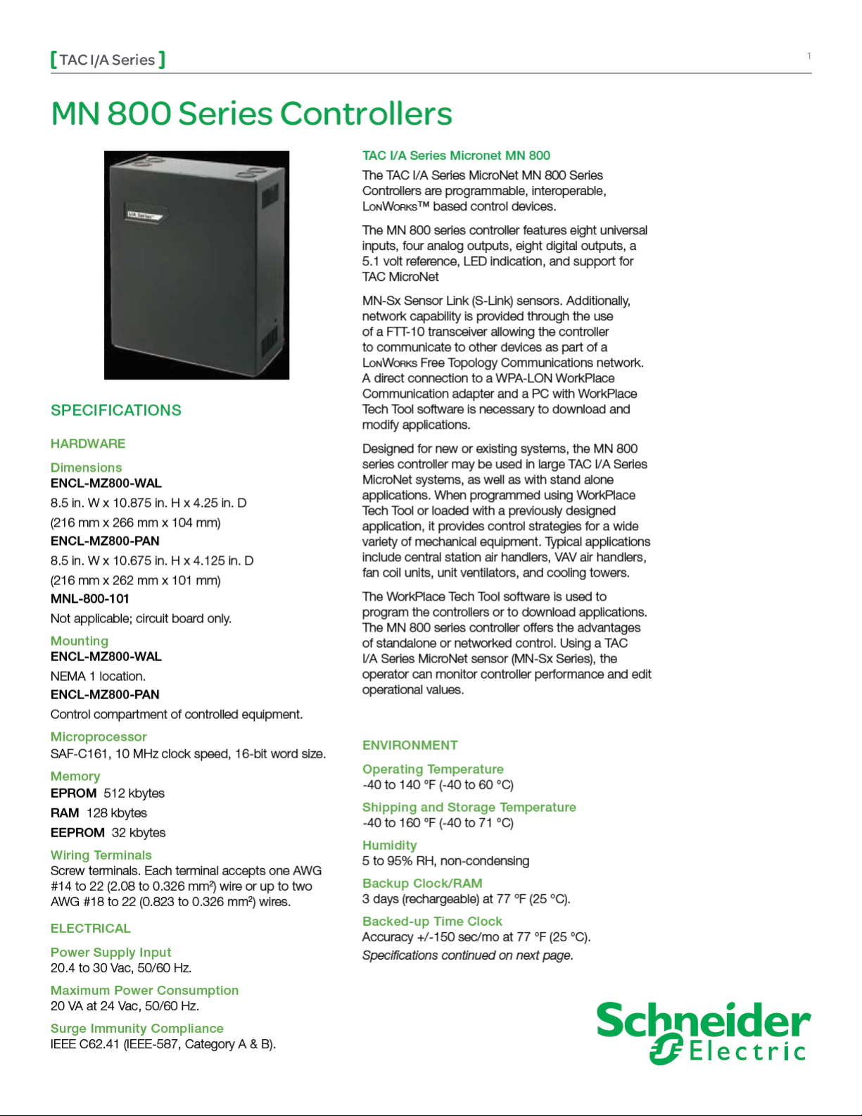
MN 800 Series Controllers
2
Specifications continued from first page.
AGENCY LISTINGS
US
FCC Part 15, Class A
UL 916, File #E71385 Category PAZX
Canadian
UL Listed to Canadian Safety Standards
(CAN/CSA 22.2)
Australian
Meets requirements to bear the C-Tick Mark
European Community- EMC Directive
EN55022 (Emissions, Class A)
EN50081-1 (EMC, Immunity)
EN50082-1 (AC Mains Power Line Voltage)
INPUTS AND OUTPUTS
Pulse Count
IN1 Only
Minimum pulse count rate of 1 per 4 min.
Maximum pluse count rate of 10 per sec (50 msec
minimum On or Off time per pulse).
IN2-IN8
Minimum pulse count rate of 1 per 4 min.
Maximum pluse count rate of 1 per sec (0.5 sec
minimum On or Off time per pulse).
Analog Outputs
Quantity 4
Type 0-20 mA range programmable source into 80 to
550 ohm load, momentary short circuit protection.
Digital to Analog Conversion Resolution 8 bit.
Digital Outputs
Quantity 8
Contact Ratings 30 VA at 24 Vac, pilot duty. 120 VA
at 120 Vac, pilot duty.
Contact Type Form C (SPDT) isolated.
Status Indication Light emitting diode.
Voltage Reference 5.1 Vdc, 20 mA maximum.
Analog to Digital Conversion Resolution
12 bit.
Universal Inputs
Quantity 8
1K ohm Balco Input -40 to 250 °F (-40 to 121°C)
range. TSMN-81011, TS-8000 Series or equivalent.
1K ohm Platinum Input -40 to 240 °F (-40 to
116 °C) range. TSMN-58011, TS-5800 Series or
equivalent.
1K ohm Copper Input -31 to 240 °F (-35 to 116 °C)
range. TS-5600 Series or equivalent.
10K ohm Thermistor w/ 11K ohm Shunt Resistor
-40 to 250 °F (-40 to 121 °C) range. TSMN-57011850, TS-5700-850 Series or equivalent.
1k Resistance 0 to 1.5k ohms.
10k Resistance 0 to 10.5k ohms.
Potentiometers 1K to 15K ohm resistance, using
5.1 V reference.
Voltage 0 to 5 Vdc.
Current 0 to 20 mA requires an external 250 ohm
shunt resistor.
Digital Input Dry Contact. Detection of closed
switch requires less than 300 ohms. Detection of
open switch requires more than 1.5K ohms.
COMMUNICATIONS
Lo n Wo r k s Networks
A L
o n Wo r k s communications network uses a
TP/FT-10 Free Topology configuration. Controllers
on a L
o n Wo r k s network can communicate with each
other in a peer-to-peer fashion. A L
has a communications speed of 78 kbps, using
unshielded, twisted-pair cabling, with connections
that are not polarity sensitive.
S-Link
The Sensor Link (S-Link) communications wiring
provides power and a communication interface for an
MN-Sx MicroNet sensor. The various MN-Sx sensors
can provide room temperature, room humidity,
setpoint adjustment, and occupancy override. This
connection uses two-wire, unshielded cable and is
not polarity sensitive. Maximum wire length allowed
between a controller and a MicroNet Sensor is 200 ft
(61 m).
o n Wo r k s network
Schneider Electric
F-26627-5 Novemb er 2009 pm
© 2009 Schneider Electr ic. All rights reserved.
Page 3

TAC I/A Series
MN 800 Series Controllers
INPUTS FROM MN-SX I/A SERIES MICRONET SENSORS
Inputs Description MN-Sx Sensor
Space Temperature 32 to 122 °F (0 to 50 °C) MN-S1, MN-S1HT, MN-S2, MN-S2HT, MN-S3, MN-S3HT,
Space Humidity 5 to 95% RH, Non-condensing MN-S1HT, MN-S2HT, MN-S3HT, MN-S4HT, MN-S4HT-
Adjustable Setpoint 40 to 95 °F (4 to 35°C) MN-S3, MN-S3HT, MN-S4, MN-S4HT, MN-S4-FCS,
Override Pushbutton For standalone occupancy control or
remote status monitoring of local status
condition.
Fan Operation and Speed Fan mode selection: On, Speed (Low/
Medium/High), or Auto.
System Mode System mode selection: Heat, Cool, Off,
or Auto.
Emergency Heat Emergency heat mode selection: Enable
or Disable
MN-S4, MN-S4HT, MN-S4-FCS, MN-S4HT-FCS, MN-S5
and MN-S5HT
FCS, and MN-S5HT
MN-S4HT-FCS, MN-S5, and MN-S5HT
MN-S2, MN-S2HT, MN-S3, MN-S3HT, MN-S4, MN-S4HT,
MN-S5, and MN-S5HT
MN-S4, MN-S4HT, MN-S4-FCS, MN-S4HT-FCS, MN-S5,
and MN-S5HT
MN-S4, MN-S4HT, MN-S5, and MN-S5HT
MN-S5 and MN-S5HT
3
MODELS
Part Number Description Backed-up Time Clock
ENCL-MZ800-WAL TAC I/A Series MicroNet 800 Series
No
Controller with Wall-Mount Enclosure
ENCL-MZ800-PAN TAC I/A Series MicroNet 800 Series
No
Controller with Panel-Mount
Enclosure
MNL-800-101 TAC I/A Series MicroNet 800 Series
Yes
Controller Card
FEATURES
Complete user creation of custom control •
strategies through TAC I/A Series WorkPlace
Tech Tool software adapts the MN 800 Series
Controller to virtually any HVAC control sequence
or mechanical system.
L
o n Wo r k s• compatible applications are completely
programmable.
WorkPlace Tech Tool can be used to reconfigure •
and edit application configuration data to fit a
wide range of control requirements.
Interoperability achieved using • L
o n Wo r k s
Standard Network Variable Types (SNVTs).
Backed-up time clock provides true stand-alone •
direct digital control with optimum start stop,
scheduling functions, and backed-up RAM.
Capability to function in standalone mode or •
as part of a L
o n Wo r k s TP/FT-10 Free Topology
communications network.
Multiple controllers on a • L
create a complex network of controllers for
virtually any building control need.
Provides basic trend of up to 24 points within •
the application. Trend maintains last 48 analog
samples or digital changes of state with time
stamp. Analog sampling adjustable time rates.
o n Wo r k s FTT network
Schneider Electric
F-26627-5 Novemb er 2009 pm
© 2009 Schneider Electr ic. All rights reserved.
Page 4

 Loading...