

TAC I/A Series
2
2
Specifications continued from first page.
Low-Voltage Directive – 73/23/EEC
EN60730-1.
AMBIENT LIMITS
Operating Temperature
-40 to 131 °F (-40 to 55 °C).
Shipping and Storage Temperature
-40 to 160 °F (-40 to 71 °C).
Humidity
0 to 95% RH, non-condensing.
Wiring Terminals
Screw terminal blocks. Low voltage screw terminals
(all except high-voltage terminals) accept a single
AWG #18 (0.823 mm
2
) or smaller wire. High-voltage
screw terminals (DO5, C5, DO6, C6, DO7, and C7)
accept a single AWG #14 (2.08 mm
2
) or smaller wire.
UNIVERSAL INPUTS (3)
Universal Input characteristics are softwareconfigured to respond to one of the following input
types:
10K Thermistor with 11K Shunt Resistor
Sensor operating range -40 to 250 °F
(-40 to 121 °C), model TSMN-57011-850, TS-5700850 series or equivalent.
10K Resistance
0 to 10.5K ohms.
Balco
-40 to 250 °F (-40 to 121 °C), model TSMN-81011,
TS-8000 series or equivalent.
Platinum
-40 to 240 °F (-40 to 116 °C), model TSMN-58011,
TS-5800 series or equivalent.
1K Resistance
0 to 1.5K ohms.
Analog Voltage
Range 0 to 5 Vdc.
Analog Current
Range 0 to 20 mA requires an external
250 ohm shunt resistor.
Digital
Dry switched contact (N.O. or N.C.). Detection of
closed switch requires less than 300 ohms. Detection
of open switch requires more than 1.5 K ohms.
LINE VOLTAGE RELAY OUTPUTS
MNL-11RF3 (1)
3 A maximum at 240 Vac, cos Ø = 0.4. Form A
(SPST — normally open).
MNL-13RF3 (3)
3 A maximum at 240 Vac, cos Ø = 0.4. Form A
(SPST — normally open).
TRIAC OUTPUTS (4)
Digital outputs for switching 24 Vac (0.5 A or 12 VA
maximum total load for DO1-DO4 @ 24 Vac).
WARNING:
This controller is not suitable for exposed mounting
on a wall or panel, or in any other easily accessible
place due to the possibility of personal contact with
the mains terminals. It must be mounted inside a
suitable grounded metal enclosure.
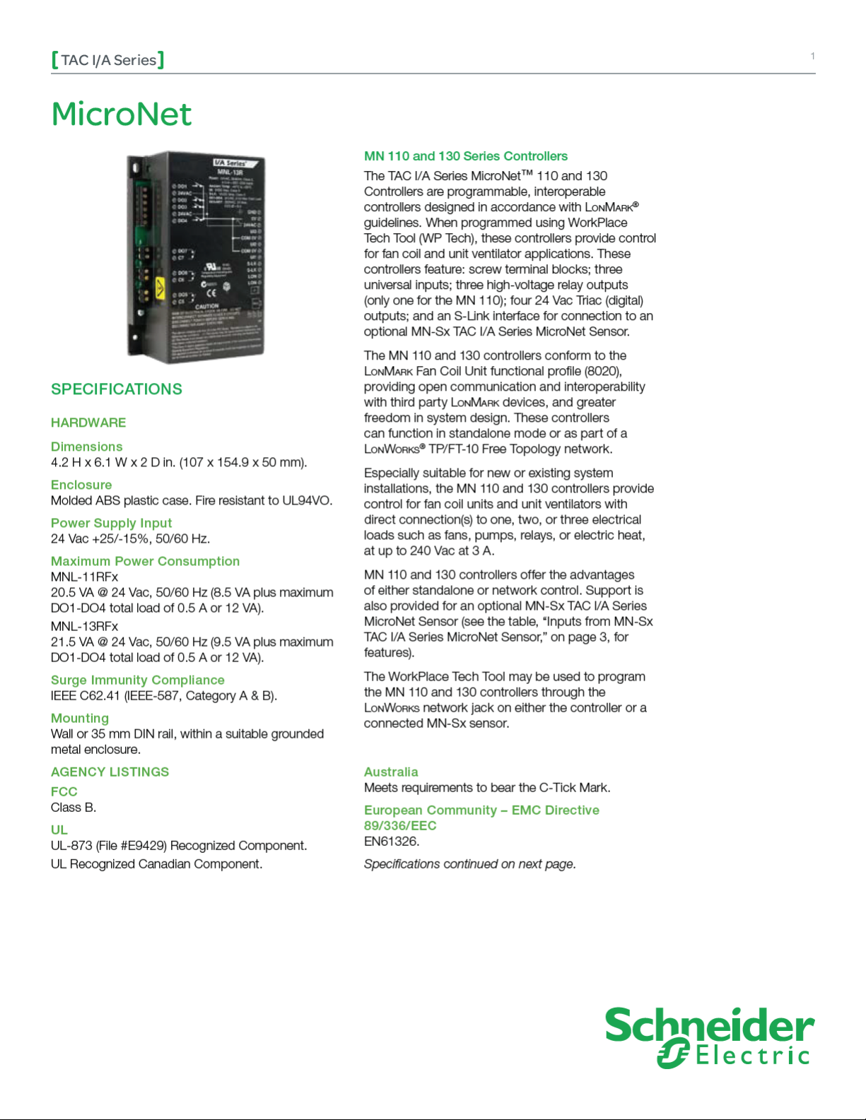
MODEL
Model Description Inputs and Outputs Profiles
3 Universal Inputs (UI)
MNL-11RF3 TAC I/A Series MicroNet
MN 110 Controller
MNL-13RF3 TAC I/A Series MicroNet
MN 130 Controller
Schneider Electric
F-27040-5 Febru ary 2011 mf
1 Line Voltage Relay
Output (DO)
4 Triac Outputs (DO)
3 Universal Inputs (UI)
3 Line Voltage Relay
Output (DO)
4 Triac Outputs (DO)
Fan Coil
Fan Coil
© 2009 Schneider Electr ic. All rights reserved.

TAC I/A Series
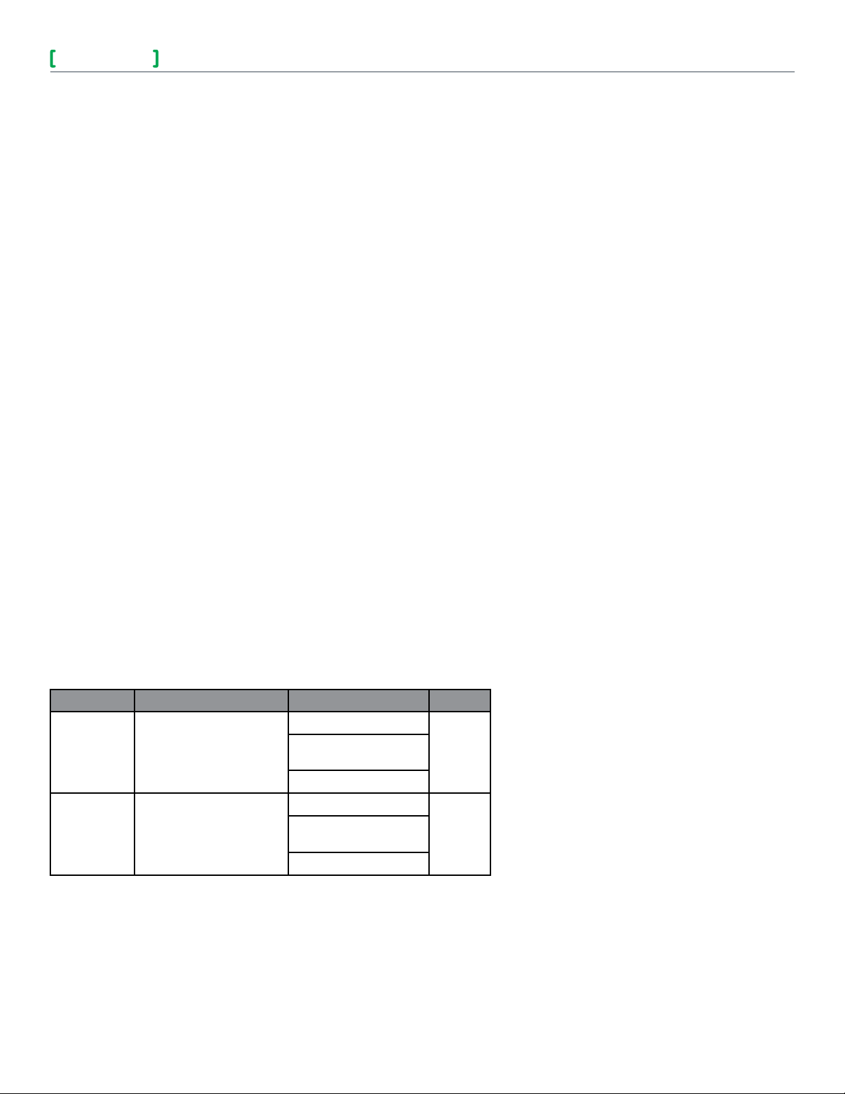
Inputs Description MN-Sx Sensor
3
3
Space Temperature 32 to 122 °F (0 to 50 °C)
Space Humidity 5 to 95% RH, Non-condensing
Adjustable Setpoint 40 to 95 °F (4 to 35°C)
For standalone occupancy control or
Override Pushbutton
remote status monitoring of local status
condition
Fan Operation and Speed
System Mode
Emergency Heat
FEATURES
• One or three high-voltage relay outputs capable of
directly powering typical 240 Vac, 3 A motors.
• Uses the L
interoperability.
• Capability to function in standalone mode or
as part of a LonWorks TP/FT-10 Free Topology
communications network.
• Onboard LED indication without cover removal.
• Compact size allows mounting in conned spaces.
• Four 24 Vac Triac outputs.
• Can be directly mounted on a wall, or on a DIN rail,
within a suitable grounded metal enclosure.
• Built-in jack for connection to a L
Software Capabilities
• Allows design of a complete custom application for
each controller.
• Conforms to the L
o n Ma r k Fan Coil Profile 8020 for
o n Ma r k guidelines.
Fan mode selection: On, Speed
(Low/Medium/High), or Auto
System mode selection: Heat, Cool, Off,
or Auto
Emergency heat mode selection: Enable
or Disable
COMMUNICATIONS
Lo n Wo r k s Networks
A L
FT-10 Free Topology configuration. Controllers on
a L
other in a peer-to-peer fashion. A L
has a communications speed of 78k baud, using
unshielded, twisted-pair cabling, with connections
that are not polarity sensitive.
S-Link
The Sensor Link (S-Link) communications wiring
provides power and a communication interface
for an MN-Sx TAC I/A Series MicroNet sensor.
The various MN-Sx sensors can provide room
o n Wo r k s network.
temperature, room humidity, setpoint adjustment,
and occupancy override. This connection uses twowire, unshielded cable and is not polarity sensitive.
Maximum wire length allowed between a controller
and a TAC I/A Series MicroNet Sensor is 200 ft
(61 m).
• WorkPlace Tech Tool is capable of recon guring
and editing application configuration data.
• Interoperability achieved through use of the
L
o n Ma r k Fan Coil Profile 8020.
MN-S1, MN-S1HT, MN-S2, MN-S2HT, MN-S3, MN-S3HT,
MN-S4, MN-S4HT, MN-S4-FCS, MN-S4HT-FCS, MN-S5 and
MN-S5HT
MN-S1HT, MN-S2HT, MN-S3HT, MN-S4HT, MN-S4HT-FCS,
and MN-S5HT
MN-S3, MN-S3HT, MN-S4, MN-S4HT, MN-S4-FCS, MNS4HT-FCS, MN-S5, and MN-S5HT
MN-S2, MN-S2HT, MN-S3, MN-S3HT, MN-S4, MN-S4HT,
MN-S5, and MN-S5HT
MN-S4, MN-S4HT, MN-S4-FCS, MN-S4HT-FCS, MN-S5,
and MN-S5HT
MN-S4, MN-S4HT, MN-S5, and MN-S5HT
MN-S5 and MN-S5HT
o n Wo r k s communications network uses an TP/
o n Wo r k s network can communicate with each
o n Wo r k s network
Schneider Electric
F-27040-5 Febru ary 2011 mf
© 2009 Schneider Electr ic. All rights reserved.

 Loading...