

Page 1
Andover ContinuumTM
Infinet II
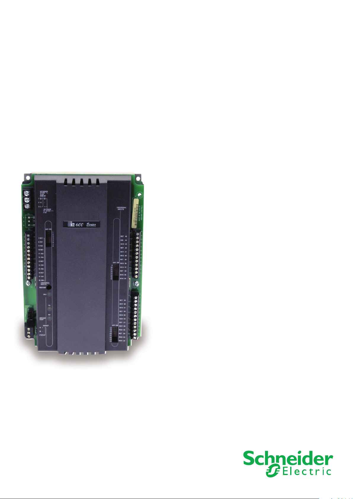
i2800 Series Local
The i2800 Series are designed for control of small Air Handling
Unit/Roof Top, and other mechanical plant equipment.
Units,
Page 2
Andover Continuum Infi net II
i2800 Series Local Controllers
Features
PRODUCT AT A GLANCE
• Powerful , Flexib le Loca l Controlle r for th e
Most Demanding Applications
• Non-Vola tile Fl ash Mem ory Prov ides U tmost
Reli ability — Stor es Both Applic ation P rogram
and Operating System
• Local, Extended Storage of Log Data
• View and Mo dify In formatio n with Optional
Smart Sensor Display
• Local, On-Board Service Port
02
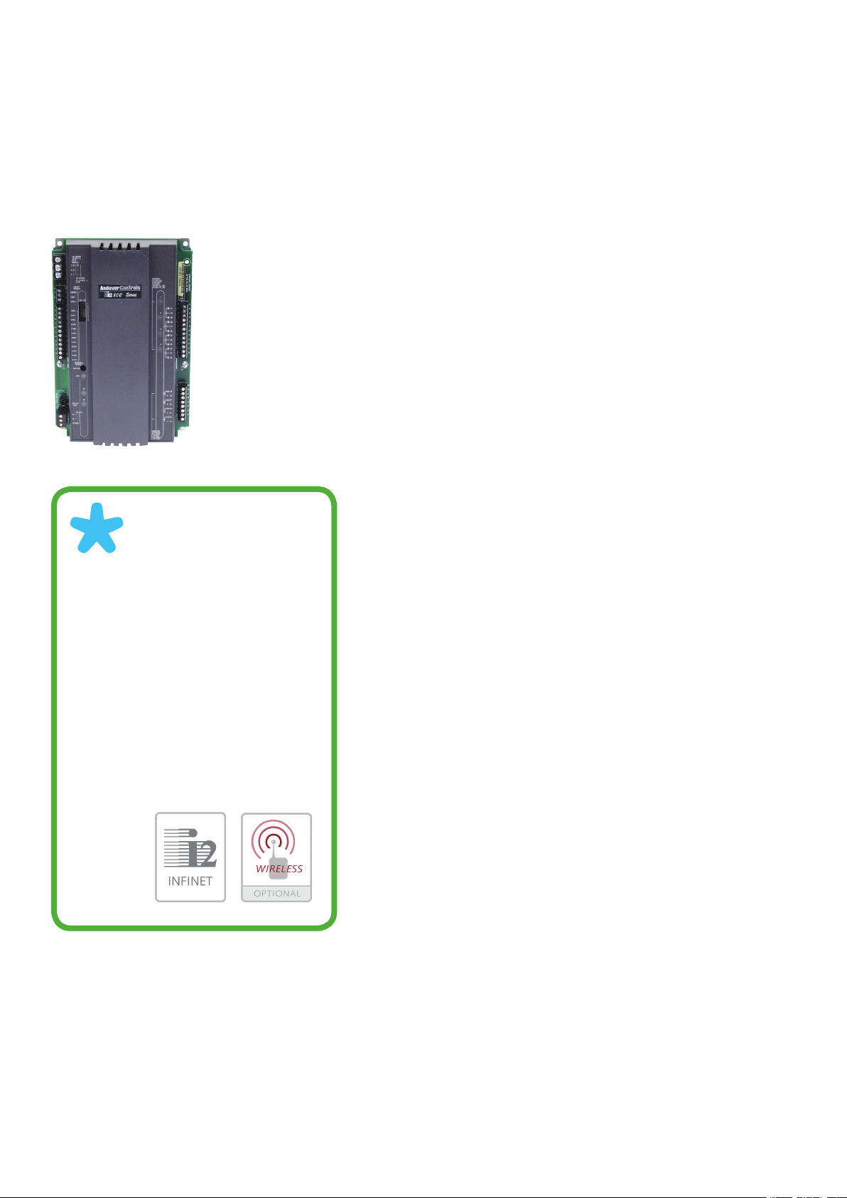
Choose the i2800 Series controller
with the confi guration that matches
your application:
• The i2800, designed for stand-alone equipment
control of Roof Top or Air Handling Units, features
eight universal inputs, one Smart Sensor/Room
Sensor input, plus eight program-controlled
digital outputs.
• The i2804, designed for stand-alone equipment
control of Roof Top or Air Handling Units, features
eight universal inputs, one Smart Sensor/Room
Sensor input, plus four program-controlled digital
outputs and four analog outputs for direct control
of devices requiring 0-10 volt control signals.
Note: The i2804 is only compatible with Andover
Continuum.
Both models feature an additional room sensor
input, which supports Andover Continuum Smart
Sensor, or any standard room temperature sensor.
The i2800 Series also features Flash memory,
increased user memory, and a fast (32-bit) processor
for faster scan times, with plenty of memory available
for data logging of your critical data.
The i2800 communicates with the entire Andover
Continuum In net RS-485 eld bus (i.e. both
In net and In net II controllers), and is compatible
with both the Andover Continuum CyberStation
and In nity SX 8000 front-ends. The i2804 is only
compatible with Andover Continuum. Up to 254
Andover Continuum Infi net devices can be networked
to any Andover Continuum network controller.
Schneider Electric
SDS-
I2800-A4.BU.N.EN.11.2007.0.00.CC
Page 3

Andover Continuum Infinet II
i2800 Series Local Controllers
03
Features
(continued)
Increased Reliability with Flash Memory
The i2800’s non-volatile Flash memory stores your
operating system and application programs, so
that in the event of a power loss, your application
will be restored when power is returned. In
addition, the Flash memory allows for easy
upgrades of your operating system via software
downloads, eliminating the need to swap out
proms. The i2800 Series controllers include an
on-board battery to safeguard your runtime data
— protecting all point data and log data from being
lost if power is removed.
Inputs
The input conguration on the i2800 Series
consists of eight full range, 10-bit Universal
inputs that accept voltage (0-5VDC), digital (on/
off), counter signals (up
signals, or supervised alarm circuits for security
applications or broken wire
Series offers an additional input to support the
Andover Continuum Smart Sensor, or any standard
room temperature sensor.
to 4Hz), temperature
detection. The i2800
Dimensional Drawings
1
3
4
2
Outputs
The i2800 contains eight Form C relay outputs,
each rated for 24 VAC/VDC, 3 Amp, while the
i2804 contains four Form C relay outputs and four
analog outputs (0-10V).
Software Capabilities
The dynamic memory of the i2800 can be
allocated for any combination of programs,
scheduling, alarming, and data logging using
the powerful Andover Continuum Plain English
programming language. Our object-oriented Plain
English language with intuitive keywords provides
an easy method to tailor the controller to meet your
exact requirements. Programs are entered into the
i2800 using the Andover Continuum CyberStation.
Programs are then stored and executed by the
i2800 controllers.
Programming multiple i2800 Series controllers
is inherently easy with Plain English. A complete
copy of one i2800 controller’s programs can be
loaded directly into other i2800 controllers without
changing any point names or programs.
Schneider Electric
SDS-
I2800-A4.BU.N.EN.11.2007.0.00.CC
Page 4

Andover Continuum Infinet II
i2800 Series Local Controllers
04
Features
(continued)
Smart Sensor Interface
The i2800 provides a built-in connection for
Andover Continuum’s Smart Sensor. The Smart
Sensor provides a 2-character LED display and
a 6-button programmable keypad that enables
operators and occupants to change setpoints,
balance VAV boxes, monitor occupancy status,
and turn equipment on and off. An enhanced
version of the Smart Sensor is also available with
a 4-digit custom LCD that provides the following
icons: PM, %, °, Setpoint, Cool, Heat, CFM, Fan,
OA, and SP.
Optional Wireless Andover Continuum
Infinet
The i2800 Series Innet controllers can also
communicate using a wireless mesh network.
Simply plug Andover Continuum Wireless Adapters
into the service ports of these controllers with
wireless compatible firmware to create a wireless
mesh network that sends and receives Andover
Continuum Infinet messages.
Dimensional Drawings
1
Power Drawing
2
Communi cations
Drawing
Sc
hneider Electric
SDS-I2800-A4.BU.N.EN.11.2007.0.00.CC
Smart S ensor and
3
Inputs D rawing
i2800
Output Drawing
4
i2804
Page 5

05
Andover Continuum Infinet II
i2800 Series Local Controllers
Specifications
i2800 Series Local Controllers
Electrical
Power
24VAC, 12-24VDC - auto sensing,
+10% -15%, 50/60 Hz
Power Consumption
25 VA
Overload Protection
Fused with 3 amp fuse. MOV protected
Software Real-Time Clock
Synchronized through Innet by
network controller
Mechanical
Operating Environment
-10°–140°F (-23–60°C),
10–95% RH (non-condensing)
Size
9.03˝ H x 6.01˝ W x 2.14˝ D
(229 H x 153 W x 54 D) mm
Weight
1.34 lbs. (0.61 kg)
Enclosure Type
UL Open class, IP 10.
Flammability rating of UL94-5V
Mounting
Panel mount
Battery
Battery Backup
Replaceable, non-rechargeable,
lithium battery. Provides 5 years typical ac-
cumulated power failure backup
of RAM memory
Communications
Communications Interface
Through Innet RS-485 eld bus
to network controller
Communications Speed
1200 to 19.2K baud
Bus Length
4,000 ft. (1,220m) standard for Innet,
I2 Inlink module allows extension to
longer distances and is required after
every group of 32 units on the network.
Bus Media
Infinet: twisted, shielded pair,
low capacitance cable
RS-485 port for implementing Wireless
Infinet II connection, including:
Standard service port, four-position
shrouded connector
Comm. Error Checking
International Standard CRC 16
Compatibility
Andover Continuum CyberStation and Inn-
ity SX 8000 systems
Note: The i2804 is compatible
with Andover Continuum (only).
05
Inputs/Outputs
Inputs
8 Universal inputs: Voltage (0-5.115 VDC);
Temperature -30°F to 230°F
(-34°C to 110°C), Digital (on/off), Counter
(up to 4Hz at 50% duty cycle, 125 ms min.
pulse width). Supervised Alarm (single or
double resistor). Current input (0 - 20 mA)
using external 250 ohm resistor.
1 Smart Sensor Temperature Input
(32°F to 105°F) (0°C to 41°C)
Input Voltage Range
0-5.115 volts DC
Input Impedance
10K ohm to 5.120V or 5M ohm
with pull-up resistor disabled
Input Resolution
5.0 mV
Input Accuracy
±15mV (±0.56°C from -23°C to
+66°C or ±1°F from -10°F to +150°F)
Digital Outputs
8 single pole single throw (SPST)
Form C relays (4 Form C on i2804)
(Any two consecutive Form C outputs can
be congured as one Form K
Tri-state)
Output Rating
Maximum 3A, 24VAC/VDC,
±1500V transients (Tested
according to EN61000-4-4)
Output Accuracy
0.1 sec. for pulse width modulation
hneider Electric
Sc
SDS-I2800-A4.BU.N.EN.11.2007.0.00.CC
Page 6

Andover Continuum Infinet II
i2800 Series Local Controllers
06
Specifications
(continued)
i2800 Series Local Controllers
Analog Outputs
4 analog outputs (i2804 only)
Output Rating
For 0-10V: 5mA maximum,
2K ohm minimum impedance,
±1000V transients (Tested according to
EN61000-4-4)
Output Resolution
0.1V for 0-10V
Connections
Power
3-position xed screw terminal connector
Inputs
12-position xed screw terminal connector
Outputs
i2800: Two 12-position xed screw
terminal connectors
i2804: One 12-position xed screw terminal
connector and One 8-position fixed screw
terminal connector
Smart Sensor
3-position xed screw terminal connector
Communications
3-position removable screw
terminal connector
Service Port
4-position shrouded connector
User LEDs/Switches
Status Indicator LEDs
CPU CPU Active
TD Transmit Data
RD Receive Data
Output Output Status (per output)
(Digital only)
Switches
RESET
Input Pull-up Resistor Switch (per input)
General
Memory
128K SRAM, 1MB FLASH
Processor
Motorola 32-bit Coldre
Agency Listings
UL/CUL 916, FCC CFR 47 Part 15,
ICES-003, EN55022, AS/NZS 3548,
Class A, CE
Options
UL864, Smoke Control System
Equipment, UUKL (i2800-S, i2804-S)
Models
i2800
Innet II i2800 Local Controller
i2800-S
Innet II i2800 Local Controller with
Smoke-Control option
i2800-WL
Wireless Innet II i2800 Local Controller
i2804
Innet II i2804 Local Controller
i2804-S
Innet II i2804 Local Controller with
Smoke-Control option
i2804-WL
Wireless Innet II i2804 Local Controller
All brand names, trademarks and registered trademarks are the property of their respective owners. Information contained within this document is subject to change
without notice.
On October 1st, 2009, TAC became the Buildings Business of its parent company Schneider Electric. This document reflects the visual identit y of Schneider Electric,
however there remains references to TAC as a corporate brand in the body copy. As each document is updated, the body copy will be changed to reflect appropriate
corporate brand changes.
Sc
hneider Electric
SDS-I2800-A4.BU.N.EN.11.2007.0.00.CC
November 2007 pdw
© 2007-20 09 Schneider Electric. All rights reserved.
 Loading...