

Page 1
Com’X 510 Energy Server
User manual
DOCA0098EN-12
09/2020
www.schneider-electric.com
Page 2

Legal Information
The Schneider Electric brand and any trademarks of Schneider Electric SE and its
subsidiaries referred to in this guide are the property of Schneider Electric SE or its
subsidiaries. All other brands may be trademarks of their respective owners.
This guide and its content are protected under applicable copyright laws and
furnished for informational use only. No part of this guide may be reproduced or
transmitted in any form or by any means (electronic, mechanical, photocopying,
recording, or otherwise), for any purpose, without the prior written permission of
Schneider Electric.
Schneider Electric does not grant any right or license for commercial use of the guide
or its content, except for a non-exclusive and personal license to consult it on an "as
is" basis. Schneider Electric products and equipment should be installed, operated,
serviced, and maintained only by qualified personnel.
As standards, specifications, and designs change from time to time, information
contained in this guide may be subject to change without notice.
To the extent permitted by applicable law, no responsibility or liability is assumed by
Schneider Electric and its subsidiaries for any errors or omissions in the informational
content of this material or consequences arising out of or resulting from the use of the
information contained herein.
Page 3
Safety information
Important information
Read these instructions carefully and look at the equipment to become familiar
with the device before trying to install, operate, service, or maintain it. The
following special messages may appear throughout this manual or on the
equipment to warn of potential hazards or to call attention to information that
clarifies or simplifies a procedure.
The addition of either symbol to a “Danger” or “Warning” safety label indicates
that an electrical hazard exists which will result in personal injury if the
instructions are not followed.
This is the safety alert symbol. It is used to alert you to potential personal injury
hazards. Obey all safety messages that accompany this symbol to avoid possible
injury or death.
Com’X 510 Energy Server
DANGER
DANGER indicates a hazardous situation which, if not avoided, will result in
death or serious injury.
Failure to follow these instructions will result in death or serious injury.
WARNING
WARNING indicates a hazardous situation which, if not avoided, could result
in death or serious injury.
CAUTION
CAUTION indicates a hazardous situation which, if not avoided, could result in
minor or moderate injury.
NOTICE
NOTICE is used to address practices not related to physical injury.
Please note
Electrical equipment should be installed, operated, serviced and maintained only
by qualified personnel. No responsibility is assumed by Schneider Electric for any
consequences arising out of the use of this material. A qualified person is one who
has skills and knowledge related to the construction, installation, and operation of
electrical equipment and has received safety training to recognize and avoid the
hazards involved.
DOCA0098EN-12 3
Page 4

Com’X 510 Energy Server
Notice
FCC
This equipment has been tested and found to comply with the limits for a Class B
digital device, pursuant to part 15 of the FCC rules. These limits are designed to
provide reasonable protection against harmful interference in a residential
installation. This equipment generates, uses, and can radiate radio frequency
energy and, if not installed and used in accordance with the instructions, may
cause harmful interference to radio communications. However, there is no
guarantee that the interference will not occur in a particular installation. If this
equipment does cause harmful interference to radio or television reception, which
can be determined by turning the equipment off and on, the user is encouraged to
try to correct the interference by one or more of the following measures:
• Reorient or relocate the receiving antenna.
• Increase the separation between the equipment and receiver.
• Connect the equipment to an outlet on a circuit different from that to which the
receiver is connected.
• Consult the dealer or an experienced radio/TV technician for help.
The user is cautioned that any changes or modifications not expressly approved
by Schneider Electric could void the user’s authority to operate the equipment.
This digital apparatus complies with CAN ICES-3 (B) /NMB-3(B).
4 DOCA0098EN-12
Page 5

Table of Contents
Safety precautions ......................................................................................9
Com’X 510 Introduction ........................................................................... 11
Com’X 510 User Interface Access ......................................................... 14
Supported Web Browsers..........................................................................14
Start Up Your Com’X ................................................................................. 14
Accessing Through the Ethernet Port With Windows ................................... 14
Accessing Through Wi-Fi Access Point Mode With Windows ....................... 16
Logging In................................................................................................18
Changing the Password ............................................................................ 19
Com’X 510 Quickstart ..............................................................................23
Quickstart Overview.................................................................................. 23
Quickstart: Setting Up and Starting Data Logging........................................ 23
Quickstart: Viewing On-board Data ............................................................23
Quickstart: Setting Up Publication..............................................................23
Com’X 510 Energy Server
Accessing Through the Ethernet Port With Other Operating
Systems............................................................................................. 15
Accessing Through Wi-Fi Access Point Mode ....................................... 17
Com’X 510 Security..................................................................................25
Security overview ..................................................................................... 25
Security features on your device ................................................................25
Security Configuration Recommendations ..................................................28
Com’X 510 Settings.................................................................................. 30
Settings Overview.....................................................................................30
Date and Time Settings ............................................................................. 30
Configuring Date and Time .................................................................. 30
Network Settings ...................................................................................... 30
Network Configuration Options ............................................................31
Selecting a Network Configuration .......................................................31
Ethernet Port Settings .........................................................................32
GPRS/3G Settings.............................................................................. 34
Wi-Fi Settings ..................................................................................... 38
Proxy Settings ....................................................................................40
Contact Management..........................................................................41
Email Settings ....................................................................................42
Publication .........................................................................................44
Publication Identification Settings......................................................... 47
File Format of CSV Export ...................................................................47
Digital Service Platform Connection ...........................................................48
Wi-Fi Access Point Settings....................................................................... 49
Activating the Wi-Fi Access Point .........................................................49
Deactivating the Wi-FI ......................................................................... 49
Site Information ........................................................................................ 50
Configuring Site Information ................................................................ 50
Data Logging............................................................................................50
Defining the Logging Intervals.............................................................. 50
Security ................................................................................................... 50
Firewall Management................................................................................ 51
DOCA0098EN-12 5
Page 6

Com’X 510 Energy Server
Port Settings.......................................................................................51
Upstream Network Access...................................................................51
Configuring Firewall Settings ...............................................................51
Disabling DPWS and SSH services......................................................52
Disabling the Password Reset Button ...................................................52
Account Lockout Policy .......................................................................52
Configuring Account Lockout Policy ..................................................... 53
Disabling Account Lockout Policy.........................................................53
Warning Banner Overview ...................................................................53
Certificates...............................................................................................54
Uploading a New Certificate................................................................. 54
HTTPS Redirection ............................................................................. 54
User Management .................................................................................... 54
Group Settings .........................................................................................55
Creating a Group ................................................................................55
Modifying Group Settings .................................................................... 56
Deleting a Group.................................................................................56
Users.......................................................................................................56
Creating a User .................................................................................. 57
Modifying a User.................................................................................57
Deleting a User................................................................................... 57
Event Settings.......................................................................................... 58
Predefined Events ....................................................................................58
Custom Events.........................................................................................58
Creating a Custom Event ..........................................................................58
Editing or Deleting a Custom Event............................................................ 60
Copying an Event .....................................................................................60
Links ....................................................................................................... 60
Configuring Links...................................................................................... 60
Viewing Links ........................................................................................... 61
Custom Page Management....................................................................... 61
Adding a Custom Web Page......................................................................61
Deleting Custom Web Pages ..................................................................... 62
Downloading a Custom Page .................................................................... 62
Viewing a Custom Web Page .................................................................... 62
Com’X 510 Communications................................................................... 63
IPv4 Address Settings...............................................................................63
Modbus TCP Access.................................................................................65
Configuring Modbus TCP/IP Filtering .........................................................67
Modbus Serial Port ................................................................................... 68
Modbus Serial Port Settings................................................................. 68
Advanced Ethernet Settings ......................................................................69
ZigBee Network Settings...........................................................................70
Com’X 510 Device settings ..................................................................... 73
Device Settings Overview .........................................................................73
Common Properties..................................................................................74
Adding a Downstream Device....................................................................76
Modifying a Device ...................................................................................77
Disconnecting a Device.............................................................................77
Reconnecting a Device .............................................................................77
Replacing a Device................................................................................... 78
6 DOCA0098EN-12
Page 7

Com’X 510 Energy Server
Deleting a Device .....................................................................................78
Measurement and Metadata Exported Per Hosted Platform .........................79
Built-In Pulse Meters................................................................................. 80
Custom Pulse Meter............................................................................ 81
Resistance Temperature Detectors ............................................................81
Custom Analog Devices............................................................................81
Discovering Connected Devices ................................................................ 81
Adding a Modbus Device Manually ............................................................82
Connecting Devices to WT4200 Modbus Receiver ...................................... 83
Connecting Devices to Smartlink ...............................................................83
Built-in Ethernet Devices ...........................................................................84
Custom Ethernet Devices ....................................................................85
Discovering Zigbee Devices ......................................................................85
Com’X 510 Measurements...................................................................... 86
Viewing the Measurements Table .............................................................. 86
Com’X 510 Commissioning ..................................................................... 87
Commissioning Overview..........................................................................87
Starting the Data Logging..........................................................................87
Starting the Publication .............................................................................88
Com’X 510 Monitoring..............................................................................89
Monitoring Overview ................................................................................. 89
Real Time Data ........................................................................................ 89
Summary Device View .............................................................................. 89
Real Time Trending .................................................................................. 90
Dashboards .............................................................................................91
Historical Data Export ...............................................................................93
Custom Web Pages.................................................................................. 93
Com’X 510 Control ...................................................................................94
Device Resets.......................................................................................... 94
Resetting Device Parameters ..............................................................94
Setting Time on Devices............................................................................94
Com’X 510 Diagnostics............................................................................ 95
Diagnostics Overview ...............................................................................95
Statistics ..................................................................................................95
Read Device Registers .............................................................................97
Communications Check ............................................................................98
Com’X 510 Custom Library ..................................................................... 99
Custom Models ........................................................................................ 99
Custom Modbus Devices ........................................................................ 101
Custom Pulse Meter Model ..................................................................... 105
Custom KYZ Pulse Meter Model .............................................................. 106
Custom Main Meter Model ...................................................................... 107
Custom Contactor or Impulse Relay......................................................... 109
Custom Analog Sensor Model ................................................................. 110
Com’X 510 Maintenance ....................................................................... 112
Logs ...................................................................................................... 112
System Settings ..................................................................................... 112
Configuration Management ............................................................... 113
Save the Configuration...................................................................... 113
Restore a configuration ..................................................................... 114
DOCA0098EN-12 7
Page 8

Com’X 510 Energy Server
Upgrade Firmware.................................................................................. 116
Replacing the SD Card ........................................................................... 117
Enabling Remote Access ........................................................................ 118
Disabling Remote Access from Cloud Services......................................... 119
Restarting the Com’X from the Web Interface ........................................... 119
Product Replacement ............................................................................. 119
Resetting the Password Locally ............................................................... 119
Resetting to Factory Settings................................................................... 120
Checklist Before Leaving Customer Site............................................. 121
Com’X 510 Troubleshooting.................................................................. 122
Metering Device Troubleshooting............................................................. 122
Modbus Device Troubleshooting.............................................................. 123
Network Troubleshooting ........................................................................ 123
Com’X Troubleshooting........................................................................... 124
Certificate Authorities ............................................................................. 127
Modbus Register Mapping..................................................................... 130
8 DOCA0098EN-12
Page 9
Safety precautions Com’X 510 Energy Server
Safety precautions
Installation, wiring, testing and service must be performed in accordance with all
local and national electrical codes.
DANGER
HAZARD OF ELECTRIC SHOCK, EXPLOSION, OR ARC FLASH
• Apply appropriate personal protective equipment (PPE) and follow safe
electrical work practices. See NFPA 70E in the USA, CSA Z462 or
applicable local standards.
• Turn off all power supplying this device and the equipment in which it is
installed before working on the device or equipment.
• Always use a properly rated voltage sensing device to confirm that all power
is off.
• Treat communications and I/O wiring connected to multiple devices as
hazardous live until determined otherwise.
• Do not exceed the device’s ratings for maximum limits.
• Replace all devices, doors and covers before turning on power to this
equipment.
Failure to follow these instructions will result in death or serious injury.
WARNING
UNINTENDED OPERATION
• Do not use the software for critical control or protection applications where
human or equipment safety relies on the operation of the control action.
• Do not use the software to control time-critical functions because
communication delays can occur between the time a control is initiated and
when that action is applied.
• Do not use the software to control remote equipment without securing it with
an authorized access level, and without including a status object to provide
feedback about the status of the control operation.
Failure to follow these instructions can result in death, serious injury, or
equipment damage.
WARNING
INACCURATE DATA RESULTS
• Do not incorrectly configure the software, as this can lead to inaccurate
reports and/or data results.
• Do not base your maintenance or service actions solely on messages and
information displayed by the software.
• Do not rely solely on data displayed in the software reports to determine if
the system is functioning correctly or meeting all applicable standards and
requirements.
• Do not use data displayed in the software as a substitute for proper
workplace practices or equipment maintenance.
Failure to follow these instructions can result in death, serious injury,
equipment damage, or permanent loss of data.
DOCA0098EN-12 9
Page 10

Com’X 510 Energy Server Safety precautions
WARNING
POTENTIAL COMPROMISE OF SYSTEM AVAILABILITY, INTEGRITY, AND
CONFIDENTIALITY
• Change default passwords to help prevent unauthorized access to device
settings and information.
• Disable unused ports/services and default accounts, where possible, to
minimize pathways for malicious attacks.
• Place networked devices behind multiple layers of cyber defenses (such as
firewalls, network segmentation, and network intrusion detection and
protection).
• Use cybersecurity best practices (for example: least privilege, separation of
duties) to help prevent unauthorized exposure, loss, modification of data and
logs, interruption of services, or unintended operation.
Failure to follow these instructions can result in death, serious injury, or
equipment damage.
10 DOCA0098EN-12
Page 11
Com’X 510 Introduction Com’X 510 Energy Server
Com’X 510 Introduction
Product Overview
The Com’X 510 energy server is a compact plug and play gateway and data
logger and is an essential part of an entry level energy management system.
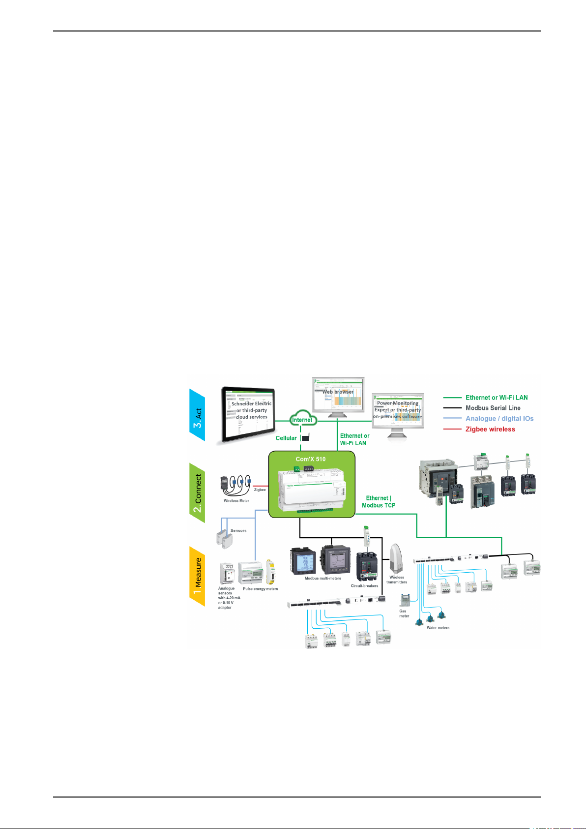
Architecture
It collects and stores consumption of WAGES (Water, Air, Gas, Electricity, and
Steam) and environmental parameters such as temperature, humidity, and CO
levels in a building. The Com’X 510 provides access to reports such as on-board
device and circuit summary pages, as well as on-board data logging. Data can be
securely accessed in real time or transmitted as a report to an Internet database
server.
Data is ready to be processed once received by the server. Data is displayed as
web pages through energy management services provided by Schneider Electric,
such as EcoStruxure
support optimization of energy performance and cost management.
From a simple metering installation with one device to large metering systems, the
Com’X 510 collects data from any Modbus TCP/Modbus serial line gateways,
pulse meters, actuators, and analog sensors.
This graphic shows possible architectures of the Com’X 510:
™
Energy Operation and EcoStruxure™Facility Expert, to
2
Main Features
The main features of the Com’X 510 are:
• real-time data in easy to understand views
• dashboard view for historical reporting
• automatic discovery of connected Modbus devices
DOCA0098EN-12 11
Page 12

Com’X 510 Energy Server Com’X 510 Introduction
• connectivity to the cloud through three media: GPRS/3G, wired Ethernet, or
Wi-Fi Ethernet
• two Ethernet ports to separate upstream cloud connection from field device
network
• four supported transfer protocols: HTTP, HTTPS, FTP, and SMTP with proxy
management
• data logging
• data export with native connection to Schneider Electric service platforms
(such as Energy Operation) and with .csv file for other database servers
• gateway functionality Modbus TCP to Modbus RTU or Modbus ASCII
• setup through on-board web pages
• compliant with electrical switchboard environment (temperature,
electromagnetic compatibility)
• local backup of configuration parameters
• ZigBee Pro with EM4300 sensors
Com’X 510 for Entry-level Energy Management
The Com’X 510 supports real-time data views from many common device types,
providing several device-specific features.
Additional energy management capabilities include:
• View real-time and historical information from multiple locations through a
supported web browser.
• Select the logging intervals and topics you want logged.
• Automatically export selected logged data to your PC for additional analysis.
• Provide data and system security through password protection and controlled
access to individual web pages, as well as through Com’X 510 firewall
management.
• Perform simple control reset commands for supported devices (for example,
min/max and accumulated energy).
• Set date and time for connected devices that support set time commands.
Schneider Electric Digital Service Platform
The energy server can be associated with Schneider Electric Digital Service
Platform.
This platform allows you to:
• Remotely manage firmware upgrade, troubleshooting, and parameter
settings.
• Provide a SIM card with worldwide coverage, by using the EBXA-GPRS-SIM
option.
• Publish collected data to Schneider Electric energy management services.
NOTE: It is recommended to use external cellular router instead of EBXAGPRS-SIM option.
EcoStruxure™Facility Expert
EcoStruxure™Facility Expert allows you to outsource energy management and
maintenance, reducing your energy costs and increasing operating efficiency in
buildings.
12 DOCA0098EN-12
Page 13

Com’X 510 Introduction Com’X 510 Energy Server
EcoStruxure™Facility Expert is a cloud-based software application from
Schneider Electric to improve energy efficiency, and manage assets and
maintenance. EcoStruxure
™
Facility Expert is used for small and medium
buildings in industry, retail, public, and healthcare markets.
EcoStruxure
™
Facility Expert provides the following features:
• Support for data acquisition hardware: meters, gateways, and sensors.
• Cloud platform for data displays.
• Consulting service from Schneider Electric expert teams.
• A network of local partners to implement solutions.
Power Monitoring Expert
The Com’X can send data in comma-separated value (CSV) files to supervision
software such as Power Monitoring Expert (PME) or third-party supervision
software.
PME is a complete, interoperable, and scalable software package for power
management applications. The software collects and organizes data gathered
from the electrical network and presents it as meaningful, actionable information
through an intuitive Web interface. Share information with key stakeholders or
across your entire operation to influence behavioral changes that can save you
money.
Additional Resources
To find these and other resources, go to www.se.com and search for “Com’X.”
Document
Com’X Instruction Sheet 5406AD002
EBXA-GPRS/EBXA-GPRS-SIM Instruction
Sheet
EBXA-WIFI Instruction Sheet 253537634
Zigbee Instruction Sheet NHA2243500
Reference Number(s)
5406AD005
5406AD006
253537613
DOCA0098EN-12 13
Page 14

Com’X 510 Energy Server Com’X 510 User Interface Access
Com’X 510 User Interface Access
Supported Web Browsers
You can access the energy server using a variety of web browsers.
Browser Browser Version
Microsoft Edge 42.0 and above
Internet Explorer IE9 and above
Firefox 20.0 and above
Chrome 24.0 and above
Recommended Web Browsers
It is recommended to use Chrome for PC.
The following browsers are recommended for tablets:
Operating System
Windows 10 • Microsoft Edge
Windows 8 • Internet Explorer
iOS • Chrome
Android • Chrome
Start Up Your Com’X
The Com’X takes time to start up. Wait for the power LED to turn green before
performing any actions.
Once the Com’X is started, most configuration modifications are taken in account
without a reboot.
Reboot Cases
The Com’X requires a reboot in the following cases:
• Upgrading the firmware.
• Restoring a configuration.
• Changing the Ethernet network settings between 2 switched ports and 2
• Inserting a GPRS or 3G modem.
• Installing a Zigbee key.
Browser
• Firefox
• Safari
• Android browser
separate ports.
Accessing Through the Ethernet Port With Windows
Access the Com’X user interface for initial setup using Windows 10.
The default configuration for Com’X Ethernet port 2 is DHCP server.
14 DOCA0098EN-12
Page 15
Com’X 510 User Interface Access Com’X 510 Energy Server
DANGER
HAZARD OF ELECTRIC SHOCK, EXPLOSION, OR ARC FLASH
• This equipment must only be installed and serviced by qualified personnel.
• Apply appropriate personal protective equipment (PPE) and follow safe
electrical work practices. See NFPA 70E in the USA, CSA Z462 or
applicable local standards.
Failure to follow these instructions will result in death or serious injury.
NOTICE
IP ADDRESS CONFLICT
Do not connect a Com'X Ethernet port to a local area network if it is configured
to DHCP server.
Failure to follow these instructions can result in impaired
communications.
1. Disconnect your local computer from all networks.
2. Connect an Ethernet cable from your local computer to the Ethernet port 2 of
the Com’X.
3. Open Windows Explorer on your local computer and click Network.
The Com’X appears in the list of devices.
4. Double-click the Com’X. The login page is opened automatically on your
default web browser.
NOTE: HTTPS is enabled by default on the Com’X configuration. The
Com’X has an autosigned security certificate. Therefore, connecting to
the energy server interface displays a security message. Before
accepting, confirm that communication with the energy server has been
established.
5. Type the username (default: admin) and the password (default: admin).
NOTE: The username and password are case-sensitive.
6. Click OK.
Related Topics
• Com’X 510 Troubleshooting
• Uploading a New Certificate
Accessing Through the Ethernet Port With Other Operating Systems
Access the Com’X user interface for initial setup using an operating system other
than Windows.
The default configuration for Com’X Ethernet port 2 is DHCP server.
DANGER
HAZARD OF ELECTRIC SHOCK, EXPLOSION, OR ARC FLASH
• This equipment must only be installed and serviced by qualified personnel.
• Apply appropriate personal protective equipment (PPE) and follow safe
electrical work practices. See NFPA 70E in the USA, CSA Z462 or
applicable local standards.
Failure to follow these instructions will result in death or serious injury.
DOCA0098EN-12 15
Page 16
Com’X 510 Energy Server Com’X 510 User Interface Access
NOTICE
IP ADDRESS CONFLICT
Do not connect a Com'X Ethernet port to a local area network if it is configured
to DHCP server.
Failure to follow these instructions can result in impaired
communications.
1. Disconnect your local computer from all networks.
2. Connect an Ethernet cable from your local computer to the Ethernet port 2 of
the Com’X.
3. Open your web browser.
4. Type [10.25.1.1] in the address field and press Enter.
NOTE: HTTPS is enabled by default on the Com’X configuration. The
Com’X has an autosigned security certificate. Therefore, connecting to
the Com’X interface displays a security message. Before accepting,
confirm that communication with the Com’X has been established.
5. Type the username (default: admin) and the password (default: admin).
NOTE: The username and password are case-sensitive.
6. Click OK.
Related Topics
• Uploading a New Certificate
Accessing Through Wi-Fi Access Point Mode With Windows
You can access the energy server user interface through Wi-Fi Access Point
Mode using Windows.
DANGER
HAZARD OF ELECTRIC SHOCK, EXPLOSION, OR ARC FLASH
• This equipment must only be installed and serviced by qualified personnel.
• Apply appropriate personal protective equipment (PPE) and follow safe
electrical work practices. See NFPA 70E in the USA, CSA Z462 or
applicable local standards.
Failure to follow these instructions will result in death or serious injury.
NOTICE
UNINTENDED EQUIPMENT OPERATION
Do not close the door of a metallic enclosure while using the Wi-Fi USB key.
Failure to follow these instructions can result in equipment damage.
1. Connect the Wi-Fi USB key to a USB port on the energy server.
2. Press the Wi-Fi button on the energy server.
The Wi-Fi button LED flashes green.
3. On your local computer, connect to the energy server wireless network using
the Windows Wireless Network configuration window.
4. Open Windows Explorer on your local computer and click Network. The
energy server appears in the list of devices.
16 DOCA0098EN-12
Page 17
Com’X 510 User Interface Access Com’X 510 Energy Server
5. Double-click the energy server and the login page opens automatically in your
default browser.
HTTPS is enabled by default on the energy server configuration. The energy
server has an autosigned security certificate. Therefore, connecting to the
energy server interface displays a security message. Before accepting,
confirm that communication with the energy server has been established.
6. Type the username (default: admin) and the password (default: admin).
The username and password are case-sensitive.
7. Click Ok.
Related Topics
• Com’X 510 Troubleshooting
• Uploading a New Certificate
Accessing Through Wi-Fi Access Point Mode
You can access the energy server user interface using Wi-Fi Access Point Mode
on operating systems other than Windows 7/Vista.
DANGER
HAZARD OF ELECTRIC SHOCK, EXPLOSION, OR ARC FLASH
• This equipment must only be installed and serviced by qualified personnel.
• Apply appropriate personal protective equipment (PPE) and follow safe
electrical work practices. See NFPA 70E in the USA, CSA Z462 or
applicable local standards.
Failure to follow these instructions will result in death or serious injury.
NOTICE
UNINTENDED EQUIPMENT OPERATION
Do not close the door of a metallic enclosure while using the Wi-Fi USB key.
Failure to follow these instructions can result in equipment damage.
1. Connect the Wi-Fi USB key to a USB port on the energy server.
2. Press the Wi-Fi button on the energy server.
The Wi-Fi button LED flashes green.
3. On your local computer, connect to the energy server wireless network using
the Windows Wireless Network configuration window.
4. Open your browser.
5. Type [10.25.2.1] in the address field and press Enter.
HTTPS is enabled by default on the energy server configuration. The energy
server has an autosigned security certificate. Therefore, connecting to the
energy server interface displays a security message. Before accepting,
confirm that communication with the energy server has been established.
6. Type the username (default: admin) and the password (default: admin).
The username and password are case-sensitive.
DOCA0098EN-12 17
Page 18

Com’X 510 Energy Server Com’X 510 User Interface Access
7. Click Ok.
Related Topics
• Uploading a New Certificate
Logging In
You need to log in to access the energy server’s user interface.
If multiple sessions are opened, only the first session can be used to edit
parameters. Sessions opened after the first session are read-only.
1. Select your language.
2. Type the username and the password.
NOTE: The username and password are case-sensitive.
3. Click Connect to be logged in to the configuration web page.
NOTE: HTTPS is enabled by default on the Com’X configuration. The Com’X
has an autosigned security certificate. Therefore, connecting to the Com’X
interface displays a security message. Before accepting, confirm that
communication with the Com’X has been established.
Related Topics
• Uploading a New Certificate
Logging In for the First Time
There are special instructions when you log in to the user interface for the first
time.
The web server is a tool for reading and writing data. It controls the state of the
system, with full access to all data in your application. You will be prompted to
change your password the first time you log in to prevent unauthorized access to
the application.
UNAUTHORIZED DATA ACCESS
• Immediately change the default password to a new, secure password.
• Do not distribute the password to unauthorized or otherwise unqualified
Failure to follow these instructions can result in equipment damage.
A secure password should not be shared or distributed to unauthorized personnel.
The password should not contain any personal or obvious information.
NOTICE
personnel.
1. Log in as the default administrator.
Username and password: admin
2. Read the License Agreement completely.
NOTE: The Accept button will remain grayed until you scroll to the
bottom of the User License Agreement.
3. Accept the License Agreement.
18 DOCA0098EN-12
Page 19
Com’X 510 User Interface Access Com’X 510 Energy Server
4. Enter a new password.
It must contain:
• 8 characters
• 1 uppercase letter
• 1 numeric digit
• 1 special character
Changing the Password
You will need to change the password after the first login and will be directed
automatically to the username/password page.
1. Click the username/admin link
2. Enter the current password.
3. Enter a new password.
4. Confirm the new password.
5. Click OK.
User Session Timeout
The login session terminates after the configured Session Inactivity Time-out
interval for the user group.
Related Topics
• Group Settings
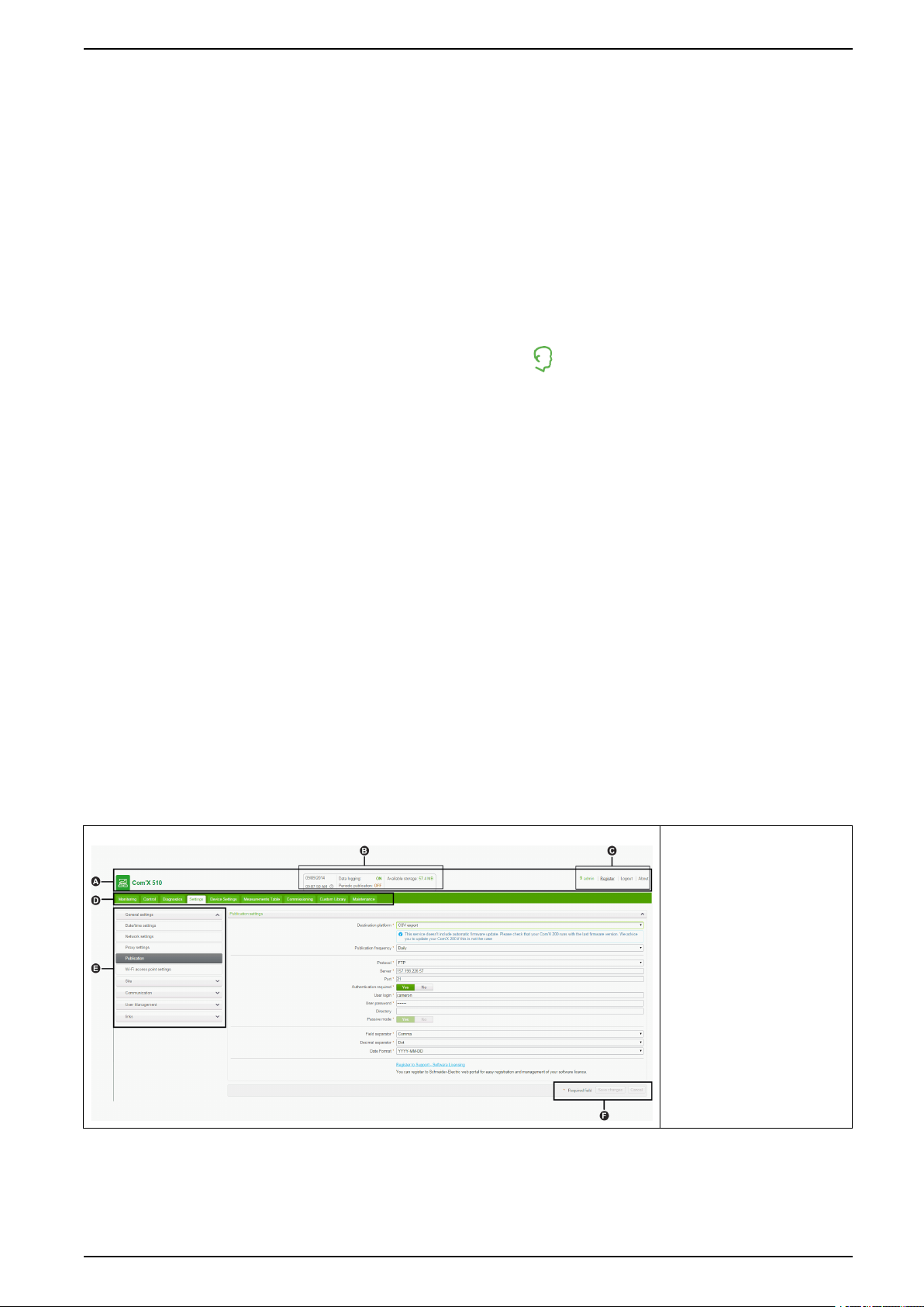
User Interface Overview
The web user interface allows you to commission your Com’X 510
This graphic shows the interface layout:
in the banner.
A. Banner
B. Gateway status
C. Generic information
D. Main tabs
E. Subtabs
F. Action buttons
Banner
The banner displays the following information at the top of all pages:
DOCA0098EN-12 19
Page 20
Com’X 510 Energy Server Com’X 510 User Interface Access
Main Tabs and Subtabs
Action Buttons
Status Data Logging: Displays status of data logging, which can be activated in
the Commissioning tab.
Periodic Publication: Displays publication status, which can be activated
in the Commissioning tab.
Available Storage: Shows available storage for data logging.
Generic Information Username/admin link: Displays the connected user.
About: Click to access information on your Com’X 510 and GPRS or 3G
modem (serial number and MAC address), IPv4 Ethernet ports, IPv6
address, and software versions.
Logout: To log out of the session, click Logout or close your browser. It is
recommended to log out of the Com’X 510 when not in use.
Time: Displays the time as set in the Date/Time Settings.
Subtabs display the submenus under the selected main tab. You can use your
web browser to bookmark each subtab of the Com’X 510 web interface.
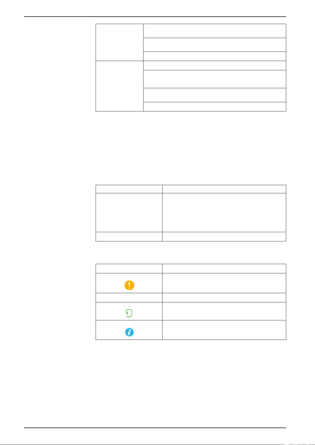
The action buttons correspond to the selected tab and vary. This table describes
the interface buttons:
Icons
Button Action
Save changes Validates the modifications. Disabled when:
• there is no change in the web page.
• a mandatory field is left blank. The field is highlighted in
red.
• inappropriate characters are entered in a field. The field is
highlighted in red.
Cancel Cancels the modifications to return to the last saved settings.
Icon
* Fields marked with a red star are required fields.
Description
Indicates that the information necessary to complete the energy
server configuration and activation of data logging and
publication is unavailable for the tab.
Indicates the user that is logged in for the current session.
Contains information about configuration in the open menu.
Related Topics
• Configuring Date and Time
User Interface Features
The user interface organizes the features in main tabs and subtabs.
20 DOCA0098EN-12
Page 21

Com’X 510 User Interface Access Com’X 510 Energy Server
Main Tab Subtab
Settings General Settings Configures the date and time, network settings, proxy settings,
Site Settings • Contains the name of the site. This field is used by Energy
Communication Configures the Modbus serial port, Modbus gateway, TCP/IP
Security Update SSL certificate and firewall settings.
User Management Create and edit groups and users.
Links Configure file and URL documentation links.
Events Configure event settings and define custom events.
Custom Page Management Create and add custom web pages to the Com’X.
Device Settings
Measurements Table
Commissioning
–
–
–
Description
publication parameters, and Wi-Fi access point settings.
Operation.
• Configures the logging interval for each commodity and for
environmental parameters.
filtering, and advanced Ethernet settings. Setup and create a
ZigBee network.
Configures the metering architecture and the data to log and
publish.
Displays meters with metadata and data to be logged.
• Checks the system configuration.
• Starts or stops data logging.
• Starts, stops, or tests data publication.
Monitoring Real Time Data Provides basic readings of selected devices. Features include
Dashboards Provides graphical representation of energy consumption
Control Device Resets Allows execution of resets defined for the device, and displays the
Set Device Time Date and time resets are shown only when the device supports
Diagnostics Statistics Displays diagnostic data used to troubleshoot network problems.
Read Device Registers Allows users to read register data from local and remote Modbus
Communications Check Tests the communications health of Modbus devices configured on
Custom Library
Maintenance Logs Shows the date, time, and description of:
–
single device and summary views.
information aggregated over time for devices enabled for data
logging and provides trending information for other electrical
properties.
date and time each reset function was performed.
them.
devices connected to the Com’X.
the Com’X.
• Create a custom device model, new device model or based on
an existing custom device model in the library.
• Modify and delete custom models
• Import and export custom models.
• changes in the configuration
• errors detected during logging
• publication steps and status
• communication interruption with metering devices
• unsuccessful login attempts
System Settings • Allows you to back up and restore a Com’X configuration.
• Activates the remote access for Schneider Electric technical
support.
• Upgrades the Com’X firmware.
• Allows you to manually restart the Com’X.
Events • Provides log of all generated pre-defined events.
• Provides log of all pre-defined events to be published.
DOCA0098EN-12 21
Page 22

Com’X 510 Energy Server Com’X 510 User Interface Access
Related Topics
• Com’X 510 Settings
• Com’X 510 Communications
• Com’X 510 Device settings
• Com’X 510 Commissioning
• Com’X 510 Monitoring
• Com’X 510 Control
• Com’X 510 Custom Library
• Com’X 510 Diagnostics
• Com’X 510 Maintenance
22 DOCA0098EN-12
Page 23

Com’X 510 Quickstart Com’X 510 Energy Server
Com’X 510 Quickstart
Quickstart Overview
This chapter describes how to perform common tasks with the Com’X 510. For a
full description of the feature outlined in each, see the topics to which it points.
NOTE: Ensure your Com’X is running the latest firmware. Go to www.
schneider-electric.com/en/download/ to download the latest version of the
firmware.
Quickstart: Setting Up and Starting Data Logging
Below are the general tasks related to starting data logging. There may be
additional steps for publishing to a specific platform.
1. Add the downstream devices as in Adding a Downstream Device, page 76.
There are additional configuration tasks for each type of device:
– Devices That Can Connect to Digital Inputs
– Devices That Can Connect to Analog Inputs
– Modbus Devices
– Ethernet Device Configuration Parameters, page 84
2. Select the measurements to log as in Selecting Measurements to Log or
Publish, page 79
3. Define the logging intervals as in Defining the Logging Intervals, page 50
4. Start the data logging as in Starting the Data Logging, page 87.
Quickstart: Viewing On-board Data
You can view real time and logged data on the Com’X 510 without having to
connect to a hosted platform. Below are the steps for viewing on-board data.
1. Add the downstream devices as in Adding a Downstream Device, page 76.
There are additional configuration tasks for each type of device:
– Modbus Devices
– Ethernet Device Configuration Parameters, page 84
2. Complete the following steps to view an Energy dashboard or Historical
Trending. Skip to step 3 to view real time data.
a. Selecting Measurements to Log or Publish, page 79
b. Defining the Logging Intervals, page 50
c. Starting the Data Logging, page 87.
NOTE: The amount of data collected affects the ability to display certain
dashboard options, for example a year over year dashboard.
3. View real time data for one or more devices: Viewing Real Time Data for a
Single Device, page 89 or Viewing a Device Summary, page 90.
Quickstart: Setting Up Publication
The steps below are a summary of publishing options. Refer to the appropriate
sections for a full description of publishing per platform.
DOCA0098EN-12 23
Page 24

Com’X 510 Energy Server Com’X 510 Quickstart
1. Choose the platform and publication frequency as in Selecting Platform and
Publication Frequency, page 44. For each platform, see these related tasks:
– For a connection to a Schneider Electric subscribed service via Digital
™
Service Platform (for example, EcoStruxure
Facility Expert), see
Connection, page 48.
– For .csv export options, you may want to refer to File Format of CSV
Export, page 47.
2. Define the transfer protocol as in Define the Transfer Protocol, page 44
3. Start the publication as in Starting the Publication, page 88
24 DOCA0098EN-12
Page 25

Com’X 510 Security Com’X 510 Energy Server
Com’X 510 Security
Security overview
Your Schneider Electric product is equipped with security-enabling features.
These features arrive in a default state and can be configured for your installation
needs. Please note that disabling or modifying settings within the scope of these
individual features can impact the overall security robustness of the device and
ultimately the security posture of your network in either positive or negative ways.
Review the security intent and recommendations for the optimal use of your
device’s security features.
Products are hardened to increase security robustness. This is an ongoing
process consisting of secure development practices, inclusion of security features
and testing at our security test facilities. Following system hardening best
practices is also necessary to help ensure your overall system security.
See the Cybersecurity Hardening Best Practices white paper for suggested best
practices.
Security features on your device
Your device comes with security features that you can configure to help protect
against unauthorized configuration and access to your device’s data through its
user interfaces or communications.
User Management
User Management allows you to create user groups with configurable
permissions for Com’X features. You can restrict access to features by assigning
individual users to a group.
There are two default groups:
• administrator: Modification rights for all features; you cannot modify this
group.
• guest: Viewing rights for selected features. Only an administrator can modify
this group.
Only an administrator can add, modify, or remove users and groups.
Related Topics
• User Management
Password Requirements
The Com’X incorporates complex password requirements.
Each user is prompted to change their password the first time they log in to
prevent unauthorized access to the application. It is recommended to schedule
regular changes to your password.
Related Topics
• Logging In for the First Time
HTTPS Connection
Your connection to the Com’X web server is HTTPS by default.
DOCA0098EN-12 25
Page 26

Com’X 510 Energy Server Com’X 510 Security
The Com’X has a self-signed security certificate. Therefore, connecting to the
Com’X interface displays a security message. Before accepting, confirm that
communication with the Com’X has been established.
HTTPS Redirection is enabled by default. It is recommended to leave this setting
enabled to secure communications between PC and the Com’X.
HTTPS Proxy is supported in Settings > General Settings. The proxy address
and port number are provided by your network administrator, or you can retrieve
these values in the Internet Options of a PC connected to the LAN.
Related Topics
• Proxy Settings
• Uploading a New Certificate
Secure Data Export
Using a secure protocol when publishing data logs can help prevent interception
and corruption of data logs.
Secure publication options include:
• HTTPS when publishing data as a .csv file or publishing to Energy Operation.
• SMTP with connection security mode to TLS/SSL or STARTTLS when
publishing a .csv file over SMTP. The default mode is None.
• DSP (a Schneider Electric hosted platform)
Destination platform is not configured by default. If you are publishing to a
location other than DSP, you must configure the protocol in Settings > General
Settings > Publication, then Email Settings if using SMTP.
Firewall Management
Related Topics
• Define the Transfer Protocol
• Configuring the SMTP Server
Firewall management allows you to configure network access.
You can configure items such as:
• Enable or disable ports.
• Configure port numbers per interface (Eth1, Eth2, WiFi, GPRS/3G), except
where noted in Port Settings.
• Enable upstream network access.
• Enable Account Lockout policy.
Disabling unused ports (determined by your network selection in Settings >
General Settings > Network Settings) can help prevent unauthorized access.
Upstream Network Access
This feature allows downstream devices to access servers (such as DNS, SNTP,
and SMTP) on the upstream network.
Upstream Network Access is disabled by default. It is recommended to leave
this setting disabled unless it is required to publish data or send event messages
from downstream clients.
26 DOCA0098EN-12
Page 27

Com’X 510 Security Com’X 510 Energy Server
Account Lockout Policy
Account lockout feature disables a user account when the number of failed login
attempts exceeds the set limit within a predetermined time interval. You can
configure the following:
• Enable account lockout Account lockout policy is enabled by default. Select
No to disable this feature. It is recommended to keep the Account Lockout
feature enabled to secure the device from unauthorized access.
• Reset account lockout counter (number of attempts) determines the number
of invalid login attempts allowed before user account gets disabled. The
default is set to 10 attempts.
• Account lockout duration (minutes) determines amount of time user account
remains disabled. The default is set to 15 minutes.
Disabling Account Lockout Policy
NOTE: It is recommended to keep the Account Lockout enabled to better
secure the device from unauthorized access.
Related Topics
Communications
• Port Settings
• Selecting Measurements to Log or Publish
Ethernet Security
The Com’X supports two separate Ethernet networks for isolated device network,
for two separate infrastructure backbones, or for a switched network.
Wireless Security
Your Com’X wireless network can be secured with WPA2 (recommended),WPA,
or WEP.
Modbus TCP/IP Filtering
The Modbus TCP/IP filtering feature controls which IP addresses are allowed to
communicate with the Com’X and its downstream devices using Modbus TCP/IP.
Minimizing the number of IP address that can access the device reduces the
likelihood of unauthorized intrusions.
This feature is disabled by default. When enabled, the default access level is
Read for any Modbus TCP/IP client not in the filtered list. Setting the Default
Access field to None blocks all Modbus TCP/IP clients not in the filtered list.
It is recommended that you enable this feature, if your system architecture
permits.
Related Topics
• Configuring Modbus TCP/IP Filtering
Maintenance
Real-time access to maintenance logs allow you to check for excessive denied
accesses, unexpected firmware upgrades or unplanned backup restoration.
DOCA0098EN-12 27
Page 28

Com’X 510 Energy Server Com’X 510 Security
Configuration Backup
Configuration backup allows recovery of Com'X and device settings.
Firmware
Users can only install firmware signed by Schneider Electric.
Remote Access from Cloud Services
By default, a Com’X device connected to DSP can be accessed through remote
assistance. The Enable remote access from cloud option is enabled (ON) by
default. For security reasons it is recommended to disable this feature and enable
it only when remote access is required for technical support from Schneider
Electric.
Refer to Disabling Remote Access from Cloud Services, page 119 for additional
information.
Related Topics
• Logs
• Save the Configuration
• Restore a configuration
• Upgrade Firmware
Security Configuration Recommendations
There are some general security configuration recommendations for your device.
• Do not add more users than those who need access, and evaluate your
system needs before granting users access to critical pages, for example,
Firewall Management or Device Settings.
• Limit the number of IP addresses that have access to the Com’X.
• Do not use SHA1 certificates.
Recommended best practices for unsecure protocols
WARNING
POTENTIAL COMPROMISE OF SYSTEM AVAILABILITY, INTEGRITY, AND
CONFIDENTIALITY
• Change default passwords to help prevent unauthorized access to device
settings and information.
• Disable unused ports/services and default accounts, where possible, to
minimize pathways for malicious attacks.
• Place networked devices behind multiple layers of cyber defenses (such as
firewalls, network segmentation, and network intrusion detection and
protection).
• Use cybersecurity best practices (for example: least privilege, separation of
duties) to help prevent unauthorized exposure, loss, modification of data and
logs, interruption of services, or unintended operation.
Failure to follow these instructions can result in death, serious injury, or
equipment damage.
NOTE: Table below lists risks and best practices associated with unsecure
protocols. It is highly recommended to follow these best practices.
28 DOCA0098EN-12
Page 29

Com’X 510 Security Com’X 510 Energy Server
Unsecure protocols Risks Best Practices
SMTP • Threat of malware.
• Unauthorized access to
data.
• Threat of data leakage.
• Email contents
transferred in plain-text.
HTTP • Cross site scripting.
• Broken authentication
and session
management.
• Cross-site request
forgery.
• Eavesdropping and
tampering.
FTP • FTP brute force attack.
• Packet sniffing.
• Spoof attack.
• User credentials can be
compromised since all
authentication is done in
clear-text.
Modbus TCP/IP • Message interception.
• Information capture.
• Arbitrary command
issuance.
• Unauthorized users can
gather and /or tamper
device configurations.
For publication:
• Select SMTP with either
SSL/TLS or SMART TLS
configured for
publication.
For network configuration:
• Disable HTTP.
• Select HTTPS for
network connections.
For publication:
• Do not select HTTP.
• Select HTTPS with
authentication.
For publication:
• Do not use FTP.
• Select either HTTPS with
authentication, or SMTP
with either SSL/TLS or
SMART TLS configured
for publication.
For Modbus device
communications:
• Limit access to Modbus
Communications by use
of Modbus TCP/IP
Filtering.
• Disable the Modbus port
for each network
interface when not in
use.
DOCA0098EN-12 29
Page 30

Com’X 510 Energy Server Com’X 510 Settings
Com’X 510 Settings
Settings Overview
This section describes how to configure the general settings of the Com’X.
WARNING
INACCURATE DATA RESULTS
Do not incorrectly configure the software, as this can lead to inaccurate reports
and/or data results.
Failure to follow these instructions can result in death, serious injury,
equipment damage, or permanent loss of data.
Date and Time Settings
The Date/Time Settings subtab allows you to set the date and time by time zone
through SNTP or manually.
Configuring Date and Time
The time and date settings must be set to the current date and time before
enabling Schneider Electric Services on your Com’X.
Any manual changes on the date and time are overwritten by Digital Service
Platform. You can only edit the Timezone.
It is recommended that DST time zone is selected when using Energy Operation
to ensure consistent time stamping with the Com’X.
To set the date and time:
1. Click Settings > General Settings > Date/Time Settings.
2. Select the appropriate Timezone in the drop-down list. If a DST time zone is
3. Choose one of the following:
4. Click Save changes.
selected, the clock will automatically adjust for Daylight Saving Time.
a. Click the Today button to set the date and time automatically with the
date and time of your computer.
b. Manually enter the date and time in the date and time fields.
c. Select Yes for SNTP support, then enter an SNTP server address.
(Default: pool.ntp.org)
Network Settings
The Com’X offers several connection interfaces.
• Ethernet with two ports
• Wi-Fi
• GPRS or 3G for isolated sites or sites where the IT administrator does not
allow access to the network infrastructure.
The available interfaces are determined by the accessories connected to the
Com’X: GPRS or 3G modem or Wi-Fi USB key.
30 DOCA0098EN-12
Page 31

Com’X 510 Settings Com’X 510 Energy Server
Network Configuration Options
The Com’X features two Ethernet ports as well as a bay for a GPRS module or a
USB port for 3G modem.
This table presents the network configuration options of the Com’X:
Port
Options
GPRS/3G only Configuration
GPRS/3G and
switched network
Wi-Fi only Configuration
Wi-Fi and
switched network
2 Switched Ports
(1 IP address for
both)
2 Separate Ports
(1 IP address for
each)
(1)
Preferred usage for this port.
(2)
Available only in Wi-Fi Access Point mode.
Ethernet Port 1 Ethernet Port 2 Wi-Fi GPRS/3G
(1)
(1)
Configuration
Configuration,
data collection,
and publishing
data collection,
and publishing
Configuration
Configuration
Configuration
and data
collection
Configuration and data collection Configuration
and data
collection
Configuration and data collection Configuration,
Configuration, data collection and
publishing
Configuration
and data
publishing
(1)
(1)
and data
collection
Configuration
and data
collection
Configuration
and data
collection
(2)
(2)
(2)
(2)
Data publishing
Data publishing
–
–
–
–
NOTE: It is recommended to use an external cellular router instead of the
above configurations.
With a GPRS or 3G Modem
The GPRS or 3G modem is used to publish data.
If you want to use Ethernet for data collection, configure the Com’X in GPRS/3G
and Switched network. Otherwise the Com’X must be configured as GPRS/3G
only.
When the Com’X is configured in GPRS/3G only, the Ethernet port 2 acts as a
DHCP server. This mode allows you to connect a PC for configuration.
NOTE: It is recommended to use an external cellular router instead of the
above configurations.
If a Wi-Fi module is installed, it can be used to establish a connection with a PC, a
tablet, or a smartphone to configure the system.
With a Wi-Fi Key
A Wi-Fi key can be used to publish data. If you want to use Ethernet for data
collection, configure the Com’X in Wi-Fi and switched network. Otherwise the
Com’X must be configured as Wi-Fi only.
Wired Ethernet
If the Com’X does not use a GPRS/3G modem or a Wi-Fi module for data
publishing, the two Ethernet ports can be configured separately.
Selecting a Network Configuration
Select the appropriate network configuration for your system.
DOCA0098EN-12 31
Page 32

Com’X 510 Energy Server Com’X 510 Settings
1. Click Settings > General Settings > Network Settings.
2. Select the network configuration in the Choose your network configuration
drop-down list.
3. If necessary, enter the parameters for each connection interface displayed.
Refer to the corresponding sections.
4. Click Save changes.
5. Wait for the Com’X to reboot.
The power LED turns green when the reboot is complete.
Related Topics
• GPRS/3G Settings
• Configuring Advanced Ethernet Settings
• Configuring a Wi-Fi Network
Reboot Cases
Changing some Com’X settings can cause an automatic reboot.
Initial Network Configuration New Network Configuration
2 separate ports • 2 switched ports
• GPRS/3G and 2 switched ports
• Wi-Fi and 2 switched ports
GPRS/3G only • 2 switched ports
• GPRS/3G and 2 switched ports
• Wi-Fi and 2 switched ports
Wi-Fi only • 2 switched ports
• GPRS/3G and 2 switched ports
• Wi-Fi and 2 switched ports
2 switched ports • 2 separate ports
• GPRS/3G only
• Wi-Fi only
GPRS/3G and 2 switched ports • 2 separate ports
• GPRS/3G only
• Wi-Fi only
Wi-Fi and 2 switched ports • 2 separate ports
• GPRS/3G only
• Wi-Fi only
NOTE: It is recommended to use an external cellular router instead of the
GPRS/3G configurations. Please refer to GPRS/3G Settings, page 34 to see a
list of recommended external 3G modems.
Ethernet Port Settings
Your Com’X has two Ethernet ports.
The Ethernet ports can be configured in two modes:
• Switch mode: two Ethernet ports share the same configuration.
• Upstream/downstream mode: two Ethernet ports are configured separately.
Switch Mode Configuration
This graphic illustrates the Ethernet port configuration in switch mode:
32 DOCA0098EN-12
Page 33

Com’X 510 Settings Com’X 510 Energy Server
In switch mode, both Ethernet ports have the same settings. Using two ports
simplifies wiring:
• one port can be connected to a switch in the local network.
• one port can be used to connect a PC for configuration operations or to
connect a data collection device locally with an Ethernet port.
Upstream/Downstream Mode Configuration
This graphic illustrates the Ethernet port configuration in upstream/downstream
mode:
DOCA0098EN-12 33
Page 34

Com’X 510 Energy Server Com’X 510 Settings
In upstream/downstream mode, the two Ethernet ports have different settings and
function independently:
• one port must be used for data publishing.
• one port must be used for data collection.
The port used for data publishing (eth1) can be configured in DHCP client mode or
static IPv4 address mode. The port used for data collection (eth2) can be
configured in DHCP client, static IPv4 address, or DHCP server.
Ethernet Configuration Settings
DHCP client: The IP address is automatically assigned to the Com’X. It is
recommended to have a fixed IP address, obtained by a DSL modem or by a
network administrator.
Static IPv4 address: Type the IP, subnetwork mask, and default gateway
addresses. Addresses are assigned to the Com’X by the IT administrator.
Related Topics
• IPv4 Address Settings
Configuring the Ethernet Ports
You can configure the Ethernet ports to as two separate ports.
1. Click Settings > General Settings > Network Settings.
2. Select the Choose your network configuration field.
NOTE: If you change the configuration of the Ethernet port you are
configuring through, you will be disconnected through the browser. Begin
a new browsing session to continue configuration.
3. Select 2 Separate Ports (1 IP address for each) in the drop-down list.
4. Select DHCP client and Static IPv4 address in the Configuration mode
drop-down list.
5. In the Ethernet configuration collapsible menu, enter the parameters in the
WAN network configuration (eth1) and LAN network configuration (eth2)
fields.
The Interface Status field changes to ACTIVE (if correctly wired).
6. In General network settings collapsible menu, type the addresses in the
Default gateway, Primary DNS server, and, if necessary, Secondary DNS
server fields.
Addresses are assigned to the Com’X by the IT administrator.
7. To enable ping replies, select Yes in General network settings > Reply to
ping.
Reply to ping is disabled by default.
8. Click Save changes.
GPRS/3G Settings
Cellular access can be added to the Com’X by installing a modem under the
cover.
This table illustrates GPRS/3G settings:
34 DOCA0098EN-12
Page 35

Com’X 510 Settings Com’X 510 Energy Server
GPRS/3G Only GPRS/3G and 2 Ethernet Switched Ports (1 IP Address for Both Ports)
Cellular network options depend on the modem that is connected.
GPRS/3G/4G and wireless transmissions are sensitive to local environmental
conditions, such as weather, network availability, and other GPRS/3G/4G devices.
You could incur increased communication costs in the event of low connectivity.
3G Modems
The following 3G modems have been tested and are compatible with the Com’X.
For each modem, refer to the manufacturer's documentation for technical
specifications and detailed installation instructions.
Manufacturer/Model Antenna Notes
MultiTech (rCell) External • Recommended
• Connected via an Ethernet cable.
• This modem must be mounted to the
enclosure. Refer to the manufacturer's
installation instructions.
Digi Routers External • Recommended
• Connected via an Ethernet cable.
• This modem must be mounted to the
enclosure. Refer to the manufacturer's
installation instructions.
MOXA (OnCell) External • Recommended
• Connected via an Ethernet cable.
• This modem must be mounted to the
enclosure. Refer to the manufacturer's
installation instructions.
eTIC External • Recommended
• Connected via an Ethernet cable.
• This modem must be mounted to the
enclosure. Refer to the manufacturer's
installation instructions.
DOCA0098EN-12 35
Page 36

Com’X 510 Energy Server Com’X 510 Settings
Related Topics
• Configuring Access Settings with EBXA-GPRS or a 3G Modem
• Configuring Access Settings with EBXA-GPRS-SIM Card
Installing a 3G Modem on the Com’X
You can install a 3G modem on the Com’X.
DANGER
HAZARD OF ELECTRIC SHOCK, EXPLOSION, OR ARC FLASH
• This equipment must only be installed and serviced by qualified personnel.
• Apply appropriate personal protective equipment (PPE) and follow safe
electrical work practices. See NFPA 70E in the USA, CSA Z462 or
applicable local standards.
Failure to follow these instructions will result in death or serious injury.
1. Power off the Com’X.
2. Open the Com’X front door.
36 DOCA0098EN-12
Page 37

Com’X 510 Settings Com’X 510 Energy Server
3. Connect the 3G modem.
– For modems that mount inside the Com’X, connect the modem to the
internal USB port.
– For 3G modems that do not mount inside the Com’X front cover, break off
the tab to create an opening for the cable, then connect the modem cable
to the internal USB port.
4. Close the Com’X door as shown above.
5. Power on the Com’X. The Radio Modem LED flashes to show the modem
has been detected.
Configuring Access Settings with EBXA-GPRS-SIM Card
You can only use the EBXA GPRS SIM to publish data if you are exporting data to
Digital Service Platform.
The SIM card is embedded in the GPRS modem. The access settings of this
GPRS modem are set by the Com’X.
The reference EBXA-GPRS-SIM must be selected for this GPRS modem.
DOCA0098EN-12 37
Page 38

Com’X 510 Energy Server Com’X 510 Settings
NOTE: It is recommended to use an external cellular router instead of the
EBXA-GPRS-SIM. Please refer to GPRS/3G Settings, page 34 to see a list of
recommended external 3G modems.
Configuring Access Settings with EBXA-GPRS or a 3G Modem
You need to configure access settings when using an EBXA-GPRS or 3G modem.
Install the SIM card into the GPRS modem as described in the EBXA-GPRS/
EBXA-GPRS-SIM Instruction Sheet, reference 253537613. For 3G, install the
SIM card into the 3G modem as described in the manufacturer's installation
instructions.
The EBXA-GPR/3G modem requires:
• a mini SIM 2FF type card.
• a minimum 1 MB/month data export on the telecom contract.
A robust M2M SIM card is recommended rather than a standard SIM card.
NOTE: It is recommended to use an external cellular router instead of the
EBXA-GPRS. Please refer to GPRS/3G Settings, page 34 to see a list of
recommended external 3G modems.
1. Click Settings > General Settings > Network Settings.
Wi-Fi Settings
2. Select EBXA-GPRS/3G.
3. Type the APN, Username, Password, and PIN Code provided by the access
provider.
4. Click Save changes.
NOTE: The PIN code and the password of the SIM card cannot be changed
by the energy server.
This table illustrates Wi-Fi settings:
38 DOCA0098EN-12
Page 39

Com’X 510 Settings Com’X 510 Energy Server
Wi-Fi Only
Wi-Fi and 2 Ethernet Switched Ports (1 IP Address for Both
Ports)
Use any USB port for temporary access, for example, to configure the Com’X.
For permanent use, the Wi-Fi USB key must be installed outside the enclosure for
EMC reasons. Schneider Electric provides accessories to mount the Wi-Fi key
outside the enclosure.
NOTICE
UNINTENDED EQUIPMENT OPERATION
Do not install the Wi-Fi key inside a metallic enclosure.
Failure to follow these instructions can result in equipment damage.
The Com’X does not enable Point-to-Point connections with other Wi-Fi field
devices. Wi-Fi traffic is controlled by the Wi-Fi infrastructure of the site.
Related Topics
• Wi-Fi Access Point Settings
Configuring a Wi-Fi Network
You can configure your Com’X wireless network.
1. Click Settings > General Settings > Network Settings.
2. Select WiFi only or WiFi and 2 Switched Ports (1 IP address network) in
the Choose your network configuration dropdown list.
NOTE: Schneider Electric recommends using WPA2.
3. Click Select a Wi-Fi network in the Wi-Fi settings collapsible menu.
DOCA0098EN-12 39
Page 40

Com’X 510 Energy Server Com’X 510 Settings
4. Click Refresh network list to scan all the Wi-Fi networks available.
5. Select the Wi-Fi network required. Type the key in the Secure key field if the
key does not appear automatically.
6. Select Other if the required Wi-Fi network does not automatically appear in
the list of Wi-Fi networks. Type the SSID and the key in the Secure key field.
7. Click Save changes.
Running Network Diagnostics
You can run diagnostic tests for the network and server connections.
1. Navigate toSettings > General Settings > Network Settings.
2. Click Launch diagnostic in the Diagnostic network menu.
A new Diagnostic Network window opens which shows the progress and
status of the diagnostic tests.
3. Click Start to restart the network diagnostics or click Close to exit the
Diagnostic Network window.
Proxy Settings
It is necessary to configure Internet proxy settings in the Com’X in a couple of
scenarios.
• if you use the HTTP or HTTPS protocols, and
• if the network administrator has implemented an Internet proxy on your local
network
Configuring Proxy Settings
You can configure the Internet proxy settings, if required.
The proxy address and port number are provided by your network administrator,
or you can retrieve these values in the Internet Options of a PC connected to the
LAN.
1. ClickSettings > General Settings > Proxy Settings.
2. Select the HTTP Proxy settings or HTTPS Proxy settings field.
3. Select the Enable HTTP proxy support check box.
4. Type the address and port of the proxy in the Proxy address and Proxy port
fields.
5. If proxy authentication is required, select Yes for Proxy requires
authentication, and enter the login and password to the proxy.
6. Click Save changes.
Retrieving Proxy Values
You can retrieve your network proxy values in Internet Explorer.
This graphic shows the interface to retrieve proxy values from Internet Explorer:
40 DOCA0098EN-12
Page 41

Com’X 510 Settings Com’X 510 Energy Server
A. Connections tab
B. Local Area
Network (LAN)
settings
C. Proxy server
with address and
port
1. Click the Tools menu.
2. Select Internet Options in the drop-down list.
3. Select the Connections tab.
4. Click the LAN settings button.
Contact Management
5. Read the values of the proxy in the Local Area Network (LAN) Settings
window.
6. Copy the same values into the Com’X proxy settings.
Contact Management allows you to create an address list for publishing data
over SMTP or when sending emails on event in Custom Events.
You must create at least one contact before setting up email on event.
NOTICE
DATA PRIVACY INFRINGEMENT
Comply with regional data privacy regulations and laws when using individual
email addresses and personal information.
Failure to follow these instructions can result in complaints, liability, or
penalties for non-compliance with applicable data protection regulations.
Creating a Contact
You can create a contact.
1. Click Settings > General Settings > Contact Management.
2. Type the Name and Email address, then press Enter or click +.
The Contact is added to list.
3. Click Save Recipient List.
The contacts are now available in:
• Publication settings for publishing over SMTP.
• Custom Events for setting up email on events.
To delete a contact, click the X beside the contact name, then Save Recipient
List.
DOCA0098EN-12 41
Page 42

Com’X 510 Energy Server Com’X 510 Settings
Related Topics
• Event Settings
• Configuring SMTP Transfer Protocol
Email Settings
Email Settings allows you to configure the connection to an SMTP server to
publish a .csv file over SMTP.
NOTICE
DATA PRIVACY INFRINGEMENT
Comply with regional data privacy regulations and laws when using individual
email addresses and personal information.
Failure to follow these instructions can result in complaints, liability, or
penalties for non-compliance with applicable data protection regulations.
Email Service
Configure the Com’X to send emails to deliver periodic data publications and
custom event notifications.
NOTE: Contact your network administrator to determine the correct IT
connection for port, LAN connection to Internet, and email server to use.
• Com’X sends an email to the configured email server/MTA (Mail Transfer
Agent) using SMTP protocol.
• MTA forwards the message to the email client MDA (Mail Delivery Agent).
• MDA delivers email to the client/MUA (Mail User Agent) using POP3 or IMAP
protocol.
Recommendation
• To ensure the secure delivery of email to the MTA, the Com’X must be
updated with the latest available firmware to use current secure email transfer
mechanisms. However, this will not guarantee full compatibility with the latest
version of the internet email service provider.
• Schneider Electric recommends using an on-premise email server (instead of
internet email service provider) with a stable and clear security policy defined
by the client IT department.
• Schneider Electric strongly recommends the use of “TLS/SSL” or
“STARTTLS” for the connection security mode between the Com’X and the
Email SMTP server. The “None” option is provided only for compatibility with
older Email SMTP servers.
42 DOCA0098EN-12
Page 43

Com’X 510 Settings Com’X 510 Energy Server
NOTE: Avoid using the “None” security mode option. The “None” security
mode option is not recommended as it does not support secure
communications.
• Each internet email service provider has its owns security policy and data
protection mechanisms to check the sender’s reputation, detect a spam
message, etc.
Configuring the SMTP Server
You can configure the Com’X SMTP server.
NOTE: SMTP is not a secure protocol, as login IDs and passwords are
communicated in plain text. Schneider Electric strongly recommends using SMTP
with TLS/SSL or STARTTLS connection security mode. Refer to Security
Configuration Recommendations, page 28 for additional information regarding
risks associated with unsecure protocols and recommended best practices.
NOTICE
UNAUTHORIZED ACCESS
Use SMTP only with TLS/SSL or STARTTLS connection security mode.
Failure to follow these instructions can result in equipment damage.
To configure the SMTP server:
1. Click Settings > General Settings > Email Settings, then click Yes to
enable the connection to SMTP server.
NOTE: Disabling the connection blocks SMTP publication or event emails
from being sent.
2. Type the server address (Fully qualified domain name, IP address, or host
name).
3. Select the Connection security mode: None, TLS/SSL or STARTTLS.
NOTE: Schneider Electric strongly recommends using SMTP with TLS/
SSL or STARTTLS connection security mode.
4. Type the outgoing delivery port in the Server port field. The port for the
selected security mode is provided by default.
5. Select Yes in the Authentication required field if the SMTP server requires
authentication. Type the username and the password.
6. Type the address of the email sender in the From address field. The factory
setting is in the format: Com'X[model]_SiteName_[last three digits
of the mac address]@schneider-electric.com.
NOTE: The From address must reference a valid email account.
Otherwise, emails may not be delivered.
7. Select the Email Language
8. Click Save changes.
9. Enter a valid email address in Recipient address for test, then click Send
Test Email.
Ensure the test email was received. The email is sent in the language of the
current login session, not the language selected above.
Continue configuring .csv publication over SMTP on the Publication subtab, if
necessary. To set up email on event, see Events.
Refer to the firmware release notes for a list of servers validated at the time of the
release.
DOCA0098EN-12 43
Page 44

Com’X 510 Energy Server Com’X 510 Settings
Related Topics
• Event Settings
Publication
Use the Publication subtab to select the platform to which the logged data is sent.
The Com’X can publish data to three different Schneider Electric platforms
(database servers):
• Energy Operation
• Digital Service Platform (DSP)
• CSV Export
The Com’X exports the data in the correct file format according to the selected
platform. Then the data can be analyzed in the service to which you have
subscribed.
The subscription to Energy Operation or DSP must be set up with a Schneider
Electric representative before setting up the Com’X Destination platform.
To publish to DSP, you must enable Schneider Electric Services in Settings >
General Settings > Schneider Electric Services.
With CSV Export, the Com’X exports data to your own database server in a .csv
file.
Selecting Platform and Publication Frequency
Use the Publication subtab to select the platform to which the logged data is sent
and at what frequency.
1. Click Settings > General Settings > Publication.
2. Select the Destination platform in the drop-down list.
3. Select how often the data is sent in the Publication frequency drop-down
list:
– Weekly: select the day of the week.
– Daily: the data is sent at 1:00 a.m. local time.
– For higher frequencies, publication times are calculated starting at 0:00 a.
m. For example, if Every 2 hours is selected, data is sent at 0:00 a.m.,
2:00 a.m., 4:00 a.m., and so on. If Every 3 hours is selected, data is sent
at 0:00 a.m., 3:00 a.m., 6:00 a.m., and so on.
4. Click Save changes.
The first publication occurs on the first hour that matches the selected
frequency after the Start publication task. For example, if Every 2 hours is
selected and the publication starts at 9:45 a.m., the first publication is at
10:00 a.m.
NOTE: DSP will be available as a drop-down option under Destination
platform only after you enable Schneider Electric services.
Related Topics
• Com’X 510 Commissioning
Define the Transfer Protocol
There are different protocols that you can use to export data.
The protocols in the Protocol drop-down list vary depending on the selected
platform, as shown in this table:
44 DOCA0098EN-12
Page 45

Com’X 510 Settings Com’X 510 Energy Server
Platforms
Energy Operation • FTP
Digital Service Platform Automatically defined by the
CSV export • FTP
Supported Transfer
Protocols File Format
XML
• HTTP and HTTPS
EWS
Com’X
CSV
• HTTP and HTTPS
• SMTP
Configuring FTP Transfer Protocol
You can configure FTP as the file transfer protocol for publications.
NOTE: FTP is not a secure protocol, as login IDs and passwords are
communicated in plain text. Schneider Electric strongly recommends using only
HTTPS protocol for security purposes. Refer to Security Configuration
Recommendations, page 28 for additional information regarding risks associated
with unsecure protocols and recommended best practices.
1. Click Settings > General Settings > Publication.
2. Select the Destination platform in the drop-down list.
3. Select FTP in the Protocol drop-down list.
4. Type the address of the server transporting the data in the Server field.
Server address for Energy Operation is automatically filled. Do not modify the
server address.
5. Type the outgoing delivery port in the Port field.
The factory setting is 21.
6. Select Yes in the Authentication required field for any platform requiring
authentication, for example Energy Operation.
7. Type the username and the password.
For Schneider Electric platforms, this information is given with the
subscription contract. Contact the Schneider Electric representative to
provide you with this information.
8. For CSV, type the directory information for the remote server in the Directory
field.
9. Click Save changes.
Configuring HTTP and HTTPS Transfer Protocols
You can configure HTTP or HTTPS as the file transfer protocol for publications.
NOTE: HTTP is not a secure protocol as login IDs and passwords are
communicated in plain text. Schneider Electric strongly recommends using only
HTTPS protocol. Disable HTTP on each interface for security purposes. Refer to
Security Configuration Recommendations, page 28 for additional information
regarding risks associated with unsecure protocols and recommended best
practices.
Certificate considerations for HTTPS:
• You can secure the HTTP connection to your server with TLS/SSL
technology.
• As with a web browser, the box is preloaded with all the major certificate
authorities as of the time of the firmware release. Schneider Electric offers an
update of the list of certificate authorities with the firmware updates.
This means that your HTTPS server certificates must have been issued by
one of the box's trusted certificate authorities. Check with your IT department
DOCA0098EN-12 45
Page 46

Com’X 510 Energy Server Com’X 510 Settings
to know if your HTTPS server certificate complies with this rule. If not, you can
select HTTP.
1. Click Settings > General Settings > Publication.
2. Select the Destination platform in the drop-down list.
3. Select HTTP or HTTPS in the Protocol drop-down list.
4. Type the address of the server transporting the data in the Server field.
The server address is automatically filled for Energy Operation. Do not modify
the server address for this platform.
5. Type the outgoing delivery port in the Port field.
The factory setting is 80 for HTTP and 443 for HTTPS.
6. Select Yes in the Authentication required field for any platform requiring
authentication, for example Energy Operation.
7. Type the username and the password.
For Schneider Electric platforms, this information is given with the
subscription contract. Contact the Schneider Electric representative to
provide you with this information.
The username and password are case-sensitive.
8. In the Path field, type the path to the server script executed by the web server
when the Com’X sends data to the web server.
This field is already filled with a /. Do not modify this value when Energy
Operation is selected as a platform.
9. According to your network administrator either:
– type the file name that the web server expects in the Field Name field
(only for CSV), or
– use the datafile1 factory setting.
10. Click Save changes.
Related Topics
• Certificate Authorities
Configuring SMTP Transfer Protocol
The SMTP protocol is available only with a CSV export. SMTP is not a secure
protocol. Refer to Security Configuration Recommendations, page 28 for
additional information regarding risks associated with unsecure protocols and
recommended best practices.
NOTICE
DATA PRIVACY INFRINGEMENT
Comply with regional data privacy regulations and laws when using individual
email addresses and personal information.
Failure to follow these instructions can result in complaints, liability, or
penalties for non-compliance with applicable data protection regulations.
To send the data file by email with the SMTP protocol:
1. Click Settings > General Settings > Publication.
2. Select CSV export in the Destination platform drop-down list.
3. Select SMTP in the Protocol drop-down list.
4. Enter the address of the server transporting data in the Server field.
46 DOCA0098EN-12
Page 47

Com’X 510 Settings Com’X 510 Energy Server
5. Enter the outgoing delivery port in the Port field.
6. Select Yes for Authentication required.
7. Enter the user login information and the password.
This information is given with the subscription contract. contact the local IT
representative to get this information.
NOTE: The username and password are case-sensitive.
8. Enter the email address in the From address field.
The factory setting for email is ComX[model]_SiteName_[last three
digits of the mac address]@schneider-electric.com.
9. Enter the email addresses of recipients in the To address field.
Separate the addresses with a semicolon (;).
10. Click Save changes.
Exported files are zipped to reduce the size of attached documents in the email.
Related Topics
• Creating a Contact
• Configuring the SMTP Server
Publication Identification Settings
There are publication identification settings for Energy Operation.
Field/Button
Publication ID This number is a unique identifier of the site for the Energy Operation database.
Generate new
publication ID
File Format of CSV Export
There is one file exported for each device.
Exported files are in the following naming format: Device Name_Date&time.
csv where Device Name is the name given to the slave device. The date and
time are appended to the file name in the following format: _yyyymmddhhmmss.
For example:
• Device name: Building 1 Utility Entrance
• Date/time: 20130218115216
The exported file is named Building 1 Utility Entrance_
20130218115216.csv and was exported on February 18, 2013 at 11:52:16 a.m.
Description
It is used to create a site in Energy Operation.
This ID is automatically generated by the Com’X.
This button generates a new publication ID number. Use this button whenever
you reuse:
• the Com’X for a new site.
• the current Com’X configuration on a different site.
The following table provides the details of each line of a CSV file, with sample
data:
Row Data in CSV Format
1 [Gateway Name,Gateway SN,Gateway IP Address,Gateway
MAC Address,Device Name,Device Local ID,Device Type
ID,Device Type Name,Logging Interval,Historical Intervals]
2 [ComX510_F930B8,
DN13045SBX10091,10.195.23.45,00:80:67:F9:30:B8,
DOCA0098EN-12 47
Description
This row contains the column headings for the information in
row 2.
This row contains the information about the Com’X 510 and
the logged device.
Page 48

Com’X 510 Energy Server Com’X 510 Settings
Row Data in CSV Format
COMX_008067F930B8_1,Resource-1,PM810,
PM810,30,6,23227,157.198.184.116,Building 1 Utility
Entrance,3,CM4000,15]
3 This row is left blank.
4 [...Topic ID 1, Topic ID 2, Topic ID 3] This row contains the column headings for the topic IDs
5 [...1617,1621,1625] This row contains the topic IDs of the values logged.
6 This row is left blank.
7
8 and
higher
(1)
A topic ID is a numerical reference to the quantity being logged. The name given to a quantity may slightly differ between devices and
languages. Topic IDs are used to identify the quantity regardless of the device or language.
[Error,UTC Offset (Minutes),Local Time Stamp,Apparent
Energy (kVAh),Real Energy (kWh),Reactive Energy
(kVARh)]
[0,-300,2008-10-09
14:15:00,1400738,219,1201962.707,647069.906,15]
[0,-300,2008-10-09
14:20:00,1400758,260,1201980.725,647078.602,15]
[0,-300,2008-10-09
14:25:00,1400778,198,1201998.661,647087.233,15]
Description
–
row 5. The first 3 commas are used for layout purposes in a
spreadsheet application.
–
This row contains the column headings for the data logged in
rows 8 and higher.
These rows contain the logged data.
(1)
in
Related Topics
• Selecting Measurements to Log or Publish
Digital Service Platform Connection
To publish to DSP, you must enable Schneider Electric Services in Settings >
General Settings > Schneider Electric Services.
Each state of connection to Digital Service Platform is confirmed with a green
check mark when enabled or grayed out when disabled. A red check mark
indicates an issue with the specific connection state. The three connection states
are:
Initialize – DSP agent initialized.
Authenticate – DSP connection authenticated.
Connect – DSP connection complete, and device has been identified on the
remote platform.
NOTE: Maintenance logs record Schneider Electric Services state changes.
When using the DSP connection, firmware upgrades are automatically launched.
It is recommended that you update the firmware if you want to use the DSP
platform through a slower GPRS connection.
Related Topics
• Upgrading Firmware via DSP
Enabling Schneider Electric Services
To enable Schneider Electric Services:
1. Configure Proxy Settings, if required.
2. Click Settings > General Settings > Schneider Electric Services.
3. Click Yes in the Configuration section.
4. Click Save Changes.
48 DOCA0098EN-12
Page 49

Com’X 510 Settings Com’X 510 Energy Server
All three states display in green and a confirmation message displays when DSP
connection is enabled.
NOTE: The configured date and time are synchronized periodically and
display after DSP sync time command runs automatically.
Disabling Schneider Electric Services
To disable Schneider Electric Services:
1. Click Settings > General Settings > Schneider Electric Services.
2. Click No in the Configuration section.
3. Click Save Changes.
All three states are grayed out and a confirmation message displays when DSP
connection is disabled.
Wi-Fi Access Point Settings
The USB Wi-Fi key can be used as a temporary communication medium during
the commissioning phase.
This allows you to use a laptop or a tablet to configure the Com’X.
In this case, communication is direct between the Com’X and the laptop or tablet.
The Com’X functions as a Wi-Fi access point.
Wi-Fi access can be added to the Com’X using a Wi-Fi USB key inserted under
the cover or on the front face. It is recommended to use the front face USB, as you
can easily remove the USB key after configuration is done.
Installing the Wi-Fi USB key directly on a Com’X port is allowed only for temporary
access point connection for configuration.
Activating the Wi-Fi Access Point
You can configure the USB Wi-Fi key to be used as a temporary communication
medium during the commissioning phase.
1. Click Settings > General Settings > Wi-Fi Access Point Settings.
2. Click Yes to Enable Wi-Fi access point.
3. Select the duration in the Session duration drop-down list (Default: 1 hour).
4. Click Save changes.
If Session duration is modified during a Wi-Fi access point session, the
modification is taken into account at the next session.
This setting only enables access point mode. To start the Wi-Fi access point
mode session, push the Wi-Fi button
front face. The Wi-Fi button LED flashes green.
located near the USB port on the
Related Topics
• Accessing Through Wi-Fi Access Point Mode With Windows
• Accessing Through Wi-Fi Access Point Mode
Deactivating the Wi-FI
You can end the Wi-Fi access point session.
DOCA0098EN-12 49
Page 50

Com’X 510 Energy Server Com’X 510 Settings
1. Press the Wi-Fi button on the front of the Com’X.
The Wi-Fi button LED flashes orange, and the Wi-Fi access point session
ends.
Site Information
The Site name field that appears in the Site Information collapsible menu is used
as a site name by different platforms.
All measurements are assigned to this site location.
In Energy Operation, the Site name parameter is used to create the site location
name that appears in Energy Operation platform environment.
Configuring Site Information
You can change the site name.
1. Click Settings > Site Settings > Site Information.
2. Enter the site location name.
NOTE: The site name must not include any of these characters: “/:*?<>|.
A space is not allowed in front of or after the site name.
3. Click Save changes.
Data Logging
The Com’X can log data at pre-defined intervals.
The logging interval can be set for each type of commodity, for example,
electricity, water, or gas. Each device can report only one type of commodity.
Defining the Logging Intervals
It is important to consider how much data is being logged across all devices when
selecting the logging interval and number of topics to log.
Logging too many topics per interval may affect Com’X performance, including
degraded web page response and missed logging intervals.
For example, for a logging interval of less than five minutes, it is recommended
that you log no more than 8 devices with 50 total topics.
1. Click Settings > Site Settings > Data Logging.
2. Select your country.
NOTE: This will automatically set the logging intervals of data for different
commodities in the country. You can also edit these intervals individually.
3. Click Save changes.
Security
You can configure the firewall, upload a certificate provided by your network
administrator, and control HTTPS redirection.
Security displays the Com’X firewall settings as well as the HTTPS security
certificate currently in use.
50 DOCA0098EN-12
Page 51

Com’X 510 Settings Com’X 510 Energy Server
Firewall Management
Firewall Management allows you to enable or disable the ports and configure
port numbers per interface, except where noted.
Port Settings
There are default Firewall Management settings for each protocol per interface.
Ethernet 1 Ethernet 2 Wi-Fi GPRS/3G
HTTP 80, Enabled 80, Enabled 80, Enabled 80, Disabled
(1)
HTTPS 443, Enabled
Modbus TCP 502, Disable 502, Enabled 502, Enabled 502, Disabled
(1)
Cannot be updated.
443, Enabled
NOTE: Refer to Security Configuration Recommendations, page 28 for
additional information regarding risks associated with unsecure protocols and
recommended best practices.
(1)
443, Enabled 443, Disabled
Upstream Network Access
In Firewall Management, you can enable upstream network access.
This allows downstream devices to access servers (such as DNS, SNTP, and
SMTP) on the upstream network.
The table below describes the downstream interface (where the message
originated) and the upstream interface on which the message will be forwarded,
based on your network selection.
Network Option Downstream (from) Upstream (to)
GPRS/3G only Ethernet Port 2 GPRS/3G
GPRS/3G and switched
network
Wi-Fi only Ethernet Port 2 Wi-Fi
Wi-Fi and switched network
2 Switched Ports (1 IP address
for both)
2 Separate Ports (1 IP address
for each)
For example, with the Com’X configured to use two separate Ethernet ports, an
IFE connected downstream on Com’X Ethernet Port 2 can send emails to
EcoStruxure
— — — —
— — — —
Upstream network access not available
Ethernet Port 2 Ethernet Port 1
™
Facility Expert through Ethernet Port 1.
Upstream network access is disabled by default. When enabled, access adapts to
the network configuration in Network Settings.
Configuring Firewall Settings
You can configure firewall settings.
NOTE: HTTP and Modbus are not a secure protocols. Schneider Electric
strongly recommends using only HTTPS protocol. Disable the HTTP and
Modbus ports for each interface for security purposes. If Modbus access is
required, Schneider Electric strongly recommends using Modbus IP filtering
feature for added security.
DOCA0098EN-12 51
Page 52

Com’X 510 Energy Server Com’X 510 Settings
1. Click Settings > Security > Firewall Management. Configure each interface
by protocol according to the available options above.
NOTE: Editable port numbers can be set to the default value or any port
number above 1023.
2. Alternatively, click Defaults to reset to defaults.
3. Click Save changes.
Disabling DPWS and SSH services
DPWS and SSH services are enabled by default. DPWS uses a specific port for
Com’X discovery and SSH uses a specific port for remote access by Schneider
Electric technical support. For security reasons it is recommended to disable
these services by setting the options to No and enabling them only when required.
NOTE: Com’X cannot be discovered by other devices after DPWS service is
disabled. It is recommended to record the Com’X IP address before disabling
DPWS service.
To disable DPWS and SSH services:
1. Select Settings>Firewall Management>Services.
2. Select No to disable DPWS service.
3. Select No to disable SSH service.
4. Select Save changes to save settings.
Disabling the Password Reset Button
For a Com’X installed in a publicly accessible location, you can disable the
password reset function for the Backup button.
The Backup button (
If you lose the default admin password, you must perform a factory reset on the
Com’X to reset the password to default. This destroys all logged data, user
accounts, and configuration.
IRRECOVERABLE PASSWORD
Record your device's user and password information in a secure location.
Failure to follow these instructions can result in data loss.
It is recommended to save a backup configuration before disabling the password
reset button.
) is located on the front face.
NOTICE
1. Click Settings > Security > Firewall Management.
2. Click Enable default admin reset.
3. Click No to disable the password reset button.
4. Click Save changes.
Account Lockout Policy
Account lockout feature disables a user account when the number of failed login
attempts exceeds the set limit within a predetermined time interval. This feature is
enabled by default.
You can configure the following:
52 DOCA0098EN-12
Page 53

Com’X 510 Settings Com’X 510 Energy Server
• Enable account lockout Account lockout policy is enabled by default. Select
No to disable this feature. It is recommended to keep the Account Lockout
feature enabled to secure the device from unauthorized access.
• Reset account lockout counter (number of attempts) determines the number
of invalid login attempts allowed before user account gets disabled. The
default is set to 10 attempts.
• Account lockout duration (minutes) determines amount of time user account
remains disabled. The default is set to 15 minutes.
Configuring Account Lockout Policy
To configure account lockout policy:
1. Navigate to Firewall Management.
2. Click Account lockout Policy.
3. Enter Reset account lockout counter.
4. Click Save changes.
Disabling Account Lockout Policy
NOTE:It is recommended to keep the Account Lockout enabled to better secure
the device from unauthorized access.
Warning Banner Overview
The Warning Banner allows you to display a message to warn against
unauthorized use and advice authorized users of their obligations relating to
acceptable use of the Com’X. This feature is disabled by default. Once enabled, a
user can access Com’X login page only after agreeing to the terms and conditions
displayed in the Warning Banner.
You can configure the following:
1. Navigate to Firewall Management.
2. Click Account lockout Policy.
3. Enter No to disable the account lockout policy.
4. Click Save changes.
• Enable warning banner – allows you to enable the warning banner to be
displayed for users prior to login. This is disabled by default. Once enabled,
the warning banner text field displays.
• Warning banner text –You can enter desired text to warn against
unauthorized use and notify authorized users of their obligations relating to
acceptable use of Com’X. A maximum of 4000 characters is allowed. If you
enter more than 4000 characters, the text displays in red and the Save
changes button is disabled.
• Defaults – allows you revert to default settings. The Warning Banner gets
disabled and the Warning banner text field is hidden.
Configuring Warning Banner Settings
To configure Warning Banner settings:
1. Navigate to Settings >Firewall Management.
2. Click Warning Banner Settings.
3. Click Yes to enable warning banner.
4. Enter text to be displayed in the warning banner.
DOCA0098EN-12 53
Page 54

Com’X 510 Energy Server Com’X 510 Settings
5. Click Save changes.
Disabling Warning Banner Settings
To disable Warning Banner settings:
1. Navigate to Settings >Firewall Management.
2. Click Warning Banner Settings.
3. Click Defaults to disable the warning banner.
4. Click Save changes.
Certificates
You can view the current HTTPS security certificate, upload a certificate provided
by your network administrator to the Com’X, and reset to factory default from this
page.
Uploading a New Certificate
HTTPS Redirection
You can install a new HTTPS certificate on your device.
It is recommended to create a backup of your configuration before installing a new
certificate. To update the HTTPS certificate:
1. Click Settings > Security > Certificates.
2. Click inside the text box Install a new certificate.
3. In the browser, select your *.pem file, then click Open.
4. Click Install. The Installed certificate details update to display the new
certificate.
To remove the current certificate and set the Com’X back to the factory default
certificate, click Reset.
HTTPS Redirection allows you to secure the communication between PC and
Com’X and is enabled by default.
NOTICE
UNAUTHORIZED ACCESS
Do not disable HTTPS redirection if there is sensitive or private information on
your local network.
Failure to follow these instructions can result in equipment damage.
Schneider Electric recommends using HTTPS Redirection. Disabling the HTTPS
redirection disables your browser security check and compromises the security of
your local network.
User Management
User Management allows you to create user groups with configurable
permissions for Com’X features.
54 DOCA0098EN-12
Page 55

Com’X 510 Settings Com’X 510 Energy Server
Then you can create individual user accounts and assign each user to a group,
based on the desired permissions.
Only an administrator can add, modify, or remove users and groups.
Related Topics
• Links
Group Settings
There are two default user groups: administrator and guest. You can create
additional groups, for example, Engineering, Operations, or Maintenance.
Group permissions are:
• View: a group has view-only permission for the selected feature.
• Modify: a group has read/write permissions for the selected feature. View
must also be selected to display the feature in the web view.
The table below describes permissions for each group.
Group Settings
Group Settings Interface
administrator Modify for all features.
You cannot modify administrator group permissions.
guest
User-defined Default access for a new group is view for all features. An
View for selected features.
Only an administrator can modify guest password and permissions.
administrator must assign permissions.
Below is the interface to add, modify, or delete a group.
A. Group: List of user groups
B. Session Inactivity Time-
out: Period of inactivity (in
minutes) after which a user
is logged out. Allowable
range is 15–240.
Default: 15
C. Feature menu tree: List of
Com’X features for which
you can set permissions
D. Permissions: Determines
the level of access users
have to each
feature: modify, view, or
none
Creating a Group
Only an administrator can create a new group.
1. Click Settings > User Management > Group Settings.
2. Click Add Group. A new window opens.
3. Enter the group name, then click Confirm. The group is added to the Group
list.
NOTE: You cannot modify the group name after you create the group.
Default access for a new group is view for all features.
DOCA0098EN-12 55
Page 56

Com’X 510 Energy Server Com’X 510 Settings
Modifying Group Settings
You can modify group settings except for group names or the administrator
group permissions.
1. Click Settings > User Management > Group Settings.
2. Select the group you want to modify from the Group drop-down menu.
3. Enter the Session Inactivity Time-out interval (in minutes).
4. Select a feature from the feature menu tree to view permissions for that
feature.
5. Select Yes or No for View or Modify to set permissions.
NOTE: Access to a feature is denied if No is selected for View.
6. Repeat steps 5 and 6 for each feature.
7. Click Save changes to apply the new permissions.
Deleting a Group
You cannot delete a user group if there are any users assigned to that group.
Remove users from the group, then follow the steps below.
Users
1. Click Settings > User Management > Group Settings .
2. Select the group you want to delete from the Group drop-down menu.
NOTE: You cannot delete the default administrator and guest groups.
3. Click Delete Group, then Yes to confirm deletion.
There are two default users: admin and guest. An administrator can create
additional users and assign permissions.
The table below describes login credentials for users.
Username Password
admin Default: admin
After the first time logging in,
the user is prompted to change
the password.
guest
Default: guest
Only an administrator can
change the guest password.
Admin user can change the
guest password during initial
configuration.
User Group
administrator
guest
User-defined An administrator assigns an
initial password. The user must
change the password after
logging in.
User-defined
Below is the interface to add, modify, or delete a user.
56 DOCA0098EN-12
Page 57

Com’X 510 Settings Com’X 510 Energy Server
A. Users: List of users for the Com’X. The
format for users is Login ID (First Name
Last Name).
B. Login Information:
• Login ID is the unique identifier for
the account.
• Group determines the permissions
you want the user to have.
• An administrator assigns an initial
password.
C. User Information: Includes user's first
and last name and email address
(optional).
Creating a User
New users can be created.
1. Click Settings > User Management > Users.
2. Click New User.
3. Enter the username and password.
NOTE: An administrator cannot modify the username or password after
the user is created.
Modifying a User
4. Select a user group from the Group drop-down list.
5. Enter the user's first name, last name, and email address.
6. Click Save changes.
You can modify user settings except for the username and password.
An administrator cannot modify the username or password after the user is
created. If you forget your username or password, contact an administrator to
delete the account and create a new one.
1. Click Settings > User Management > Users.
2. Select the user you want to modify.
3. Modify the fields you want to change, then click Save changes.
The user must change the password after logging in for the first time.
Related Topics
• Changing the Password
Deleting a User
If a user is logged in when you delete the account, the user receives a session
timeout notification.
Any unsaved changes made by the user are lost.
1. Click Settings > User Management > Users.
2. Select the name of the user you want to delete.
NOTE: You cannot remove the default admin and guest users.
3. Click Delete User, then Yes to confirm removal.
DOCA0098EN-12 57
Page 58

Com’X 510 Energy Server Com’X 510 Settings
Event Settings
Predefined Events
Events includes predefined and custom events that can be sent to EcoStruxure
™
Facility Expert.
Custom events can also be sent to an email recipient.
Before configuring events for EcoStruxure
™
Facility Expert, contact EcoStruxure
Facility Expert support to confirm availability of events. To send events to
EcoStruxure
™
Facility Expert through DSP, you must enable Schneider
ElectricServices in Settings > General Settings > Schneider Electric Services.
To enable/disable predefined or custom events, click Settings > Events > Event
Settings.
Predefined Events are defined in the Com’X for protection devices. Enabling
Predefined Events allows Facility Expert users to send event information from
Com’X to Facility Expert.
Your Schneider Electric Partner can help you understand how to use these events
to signal pre-trip conditions, analyze trips, and schedule periodic maintenance.
Predefined Events cannot be edited or acknowledged from the Com’X.
To enable/disable predefined events, click Settings > Events > Event Settings.
™
Custom Events
Custom Events allows you to define event conditions for any device using the
drag and drop event builder.
An event consists of the following block elements, found in the event builder
menu.
Block Element
Event Container block for event conditions, actions, and severity level field.
Event Conditions • Threshold: Set one threshold value at which an event occurs.
Devices Select the device and topic that trigger an event. For example, receive a
Value • Threshold value for the selected topic.
Actions • Send Email: The Com'X routes an email to the specified recipient
Description
• Pickup/Dropout: Set the value at which an event occurs
(pickup) and the value at which the event is no longer active
(dropout). Use this type to avoid nuisance events.
• Boolean: Create an event when a Boolean topic value changes, is
True, or is False, for example, when breaker open status is True.
• And: Allows you to combine up to three conditions for an event.
notification when the Temperature on a Temperature Probe Pt100
exceeds 26°C.
The device must be connected to the Com’X in Device Settings.
• Contact for sending email on event.
when the event conditions are met.
• Send to EcoStruxure
Action block, for example, the event description. It is recommended
to use the same or similar text as the Event Name field in the Com’X.
™
Facility Expert: You can enter text in the
Creating a Custom Event
Use the drag and drop event builder to define event conditions for any device.
58 DOCA0098EN-12
Page 59

Com’X 510 Settings Com’X 510 Energy Server
Before You Begin:
• You should be familiar with the device register lists and values.
• Enable custom events in Settings > Events > Event Settings.
• For email on event, you must enable Email Service in Email Settings and
create at least one contact in Contact Management.
WARNING
INACCURATE DATA RESULTS
• Do not incorrectly configure the software, as this can lead to inaccurate
reports and/or data results.
• Do not base your maintenance or service actions solely on messages and
information displayed by the software.
• Do not rely solely on data displayed in the software reports to determine if
the system is functioning correctly or meeting all applicable standards and
requirements.
• Do not use data displayed in the software as a substitute for proper
workplace practices or equipment maintenance.
Failure to follow these instructions can result in death, serious injury,
equipment damage, or permanent loss of data.
1. Click Settings > Events > Custom Events, then click New Custom Event.
The event builder displays.
2. Click Event Types in the event builder menu, then drag a green event block
onto the workspace.
3. Select the event's Severity: None, Low (alert), or High (Error).
NOTE: For EcoStruxure
the severity level in EcoStruxure
™
Facility Expert users, this field corresponds to
™
Facility Expert.
4. Click Event Conditions in the event builder menu, and drag a conditions
block into the "when" space, until it snaps into place.
5. Define the Event Conditions.
a. Select the device and topic.
b. For a Boolean event, select a Boolean value: Has changed, True, or
False.
c. For a threshold or pickup/dropout event, select an operator (=,<, or
>) and enter a pickup value. Enter a dropout value if applicable.
6. If the event has more than one condition, add up to two more conditions as
described above. Join more than one condition with the "and" logic block.
NOTE: You must choose the same device for each condition in an event.
7. Click Actions in the event builder menu, and drag an action block into the
"do" space.
8. Drag any unused blocks to the trash can in the bottom right corner.
9. Enter a name, then click Save changes.
NOTE: You should refer to the EcoStruxure Facility Expert commissioning
guide for best practices when creating or editing custom events which will be
sent to Facility Expert.
DOCA0098EN-12 59
Page 60

Com’X 510 Energy Server Com’X 510 Settings
Editing or Deleting a Custom Event
You can modify or remove events from the Custom Event Library.
1. Click Settings > Events > Custom Events.
2. Click the event name.
3. Either edit the event block and click Save changes, or click Delete to remove
the event from the Custom Event Library.
Related Topics
• Com’X 510 Troubleshooting
Copying an Event
You can create a new event from an existing event.
1. Click Settings > Events > Custom Events.
2. Click the existing event name.
3. Click on the green event block in the workspace, then press CTRL+C.
Links
Configuring Links
4. Click Cancel to return to the Custom Event Library.
5. Click New Custom Event.
6. Click inside the workspace, then press CRTL+V.
The event block is pasted into the workspace.
7. Edit the device, topic, or values, then click Save changes.
The Com’X 510 supports two types of documentation links.
• Local file access (stored on the Com’X 510)
• External URL access.
The Com’X 510 includes built-in links. These items cannot be edited but can be
deleted.
Related Topics
• User Management
You can add links to the Com’X.
1. Click Settings > Links > Setup Links.
The Links page opens.
2. Enter a name and description for the link.
3. Enter a number 1 to 100 in the Priority field.
NOTE: Negative priority is reserved for built-in links. Links display in
ascending order of priority.
60 DOCA0098EN-12
Page 61

Com’X 510 Settings Com’X 510 Energy Server
4. Click the type of link, then:
a. For Link to File, browse to select the file.
NOTE: Only PDF files can be uploaded. An error message displays
when you try to upload any other file type.
b. For Link to URL, enter the URL
5. Click Add. The link is added to the setup list and View Links
You can change the type of link after it has been created. To edit a link, click Edit,
make the desired changes, then click Update.
To delete a link, click the check box beside the link name, then click Remove.
Viewing Links
You can view your device’s links.
1. To view links, click Settings > Links > View Links.
2. Click the link to open the file or web page.
3. You can click Setup Links in the bottom right corner to return to the links
configuration page.
Custom Page Management
You can create and add custom web pages to the Com’X to provide building
overviews.
This section discusses how to add custom pages to the Com’X. For information on
APIs and how to create a custom page, see the Com'X 510 Custom Web Page
Technote, 7EN72-0199.
INACCURATE DATA RESULTS
• Do not incorrectly configure the software, as this can lead to inaccurate
reports and/or data results.
• Do not base your maintenance or service actions solely on messages and
information displayed by the software.
• Do not rely solely on data displayed in the software to determine if the device
is functioning correctly or meeting all applicable standards and requirements.
• Do not use data displayed in the software as a substitute for proper
workplace practices or equipment maintenance.
Failure to follow these instructions can result in death, serious injury, or
equipment damage.
WARNING
Adding a Custom Web Page
The init.js file is required for each web page.
Any file referenced by init.js is also required for the page to be valid and viewable.
Before uploading any files, compare the size of the custom page file set with the
Available Storage.
NOTE: Allowed file types are html, shtml, htm, js, jpg, jpeg, png, gif, and css.
An error message displays when you try to upload any other file type.
DOCA0098EN-12 61
Page 62

Com’X 510 Energy Server Com’X 510 Settings
NOTICE
IMPAIRED COM'X PERFORMANCE
Do not add more than 10 MB of files to Custom Page Management.
Failure to follow these instructions can impair Com'X performance.
To view the newly added web page, you must log out and log in again.
1. Click Settings > Custom Page Management.
2. Click Create, then enter the name you want to display on the web page.
3. Click OK. The web page container displays in the list of custom web pages
with a validation error.
4. Click Edit to add the web page files.
5. Click Upload, then select the custom page files from your computer.
6. Click OK. The Com’X validates that files called by init.js are present.
Deleting Custom Web Pages
You can select pages to delete, or you can delete individual files for each page.
It is recommended to remove unused pages.
1. Click Settings > Custom Page Management.
2. Select the pages you want to delete, then click Delete and Yes to confirm.
3. Alternatively, click Edit to delete files for a single web page. Select the files
you want to delete, then click Delete and Yes to confirm.
Downloading a Custom Page
You can save a custom web page for use on another Com’X of the same model.
1. Click Settings > Custom Page Management.
2. Click Edit to view the web page files.
3. Select the files you want to download, then click Download. Follow your
browser's prompts for saving and viewing downloaded files.
Viewing a Custom Web Page
You must be in a user group that has permission to view custom pages.
To view a custom page, click Monitoring > Custom Pages, then click the name of
the page you want to view.
After you add, edit, or delete custom page content, you must log out and log in
again to view the updates. An invalid page is not viewable in Monitoring. For
information on page permissions, see the Com’X 510 Custom Web Pages
Technote 7EN72-0199.
Related Topics
• User Management
62 DOCA0098EN-12
Page 63

Com’X 510 Communications Com’X 510 Energy Server
Com’X 510 Communications
IPv4 Address Settings
The Com’X supports three different operating modes for assigning the IP address.
These modes are:
• Static IPv4
• DHCP client
• DHCP server
Static IP Settings
In the Com’X, you can define the IPv4 addresses of the Ethernet interface,
subnetwork mask, and default gateway.
These settings must be consistent with the network policy of the site. The IT
administrator of the site should be contacted to provide this information.
Setting up a fixed address as a DHCP Client
You can configure the Com’X to have a fixed DHCP address when it is a DHCP
client.
You can configure the Com’X so that the IPv4 address is automatically set by the
facility DHCP server. The IT administrator of the site can be asked to configure the
DHCP server to systematically assign the same IPv4 address to the Com’X.
1. Provide the local IT manager with the MAC address of the Com’X Ethernet
port 1.
The address can be found on the label on the front face of the device or in the
About page.
2. Ask the IT manager to provide a fixed IPv4 address so that the same IP
address is always assigned to the Com’X.
The IP address is to be given by the IT manager.
3. Write down the IPv4 address:
• on the label sheet provided with the Com’X. This sheet can be adhered
inside the cover.
4. Check that the IT manager has added the Com’X to the DHCP server.
It is also possible to log in by entering the IP address provided by the IT manager
in the address bar of the browser.
This graphic shows the MAC address on the label of the Com’X:
DOCA0098EN-12 63
Page 64

Com’X 510 Energy Server Com’X 510 Communications
Related Topics
• Selecting a Network Configuration
DHCP Server Over Ethernet Port
You can configure the Com’X so that it assigns IP addresses to the network.
DHCP Server Over Wi-Fi
In that case, the Com’X configures its Ethernet interface Eth2 with the IP address
10.25.1.1.
The Com’X also starts an internal DHCP server. It enables you to assign
automatically an IP address, consistent with its own address, to any devices
connected to the same network and configured to operate as DHCP clients.
IP addresses assigned by the Com’X are in the subnetwork 10.25.1.0/24 (starting
from 10.25.1.65, 10.25.1.66, and so on). The Com’X has no routing capabilities.
As a result, no Default Gateway nor Domain Name Server are sent by this DHCP
server.
The IT administrator of the site should be contacted to confirm that the network
where the Eth2 interface of the Com’X is connected:
• is separated from the rest of the site network installation.
• does not disturb another DHCP server.
When a Wi-Fi key is connected to the Com’X, you can configure the Com’X so that
it creates a Wi-Fi access point.
In that case, the Com’X creates a Wi-Fi network with an SSID using the same
name as the Com’X but without any access restriction (no WEP nor WPA
authentication) in this mode. The Com’X configures its Wi-Fi interface with the IP
address 10.25.2.1.
The Com’X also starts an internal DHCP server on this Wi-Fi interface. It enables
you to assign automatically an IP address, consistent with its own address, to any
Wi-Fi devices that are configured to operate as DHCP clients.
IP addresses assigned by the Com’X are in the subnetwork 10.25.2.0/24 (starting
from 10.25.2.65, 10.25.2.66, and so on). The Com’X has no routing capabilities.
As a result, no Default Gateway nor Domain Name Server are sent by this DHCP
server.
Remote Access with Windows Operating Systems
You can remotely access the Com’X by using an IP address under Windows XP.
The IT administrator should be requested to provide a fixed IP address to assign
systematically the same IP address to the Com’X.
64 DOCA0098EN-12
Page 65

Com’X 510 Communications Com’X 510 Energy Server
With Windows, the Com’X is accessible under Windows Explorer when
connecting the PC to the same LAN. It is not necessary to know the IP address.
Related Topics
• Accessing Through the Ethernet Port With Windows
Modbus TCP Access
The Com’X acts as both a Modbus TCP gateway and a Modbus device by using
the internal Modbus TCP server.
Modbus TCP Gateway
NOTE: Modbus is not a secure protocol. Disable the Modbus ports for security
purposes. If Modbus access is required, Schneider Electric strongly
recommends using Modbus IP filtering feature for added security.
The Com’X acts as a Modbus gateway for wired or wireless Ethernet
communications from an upstream PC to Ethernet devices and field instruments
on the downstream network. This capability allows the user of local or cloud-based
monitoring software to access information from devices for data collection,
historical trending, analysis, and other functions.
Accessing the Internal Modbus Slave Device
The internal Modbus TCP server allows reading the digital input and analog input
values of the Com’X via various Modbus registers . These registers can be read
using Modbus slave ID 255.
After you configure the Com’X inputs in Device Settings, values are accessible
through the gateway. The register values can also be viewed in the
Measurements Table tab for measurements selected for logging.
The internal Modbus TCP server is active when Modbus TCP/IP communications
is enabled in Firewall Management.
Companion Software Modbus TCP/IP Server Function
Downstream Modbus devices can be accessed from an upstream PC running a
software application. Recommended software applications offered by Schneider
Electric include:
• Remote Setting Utility software for Masterpact and Compact NSX
• EcoStruxure
™
Power Monitoring Expert software.
Related Topics
• Modbus Register Mapping
• Firewall Management
• Selecting Measurements to Log or Publish
Modbus Gateway Settings
Modbus Gateway Settings allows you to customize network settings for your
specific environment.
The defined parameters apply to both Ethernet ports.
DOCA0098EN-12 65
Page 66

Com’X 510 Energy Server Com’X 510 Communications
Serial port
Setting Description Options
Transmission Mode Used to select how data is
transmitted over a serial
connection.
Silent Interval Extension (ms) Allows the silent interval used
to signify the end of a Modbus
RTU packet to be extended
beyond the 3.5 characters
defined by the standard.
Delay Between Frames (ms) Defines the minimum silent
time between the end of a
received response and the
beginning of a new request on
the serial line.
RTU, ASCII
Default: RTU
0–10 ms
Default: 5 ms
0, 10, 20, 30, 40, 50, 60, 70,
80, 90, 100
Default: 50 ms
TCP/IP Server
Setting Description Options
Enable Server Connection Idle
Time
Server Connection Idle Time Length of time after which a
Enable Modbus TCP/IP Proxy Setting that determines if
Enable Serial Modbus
Broadcasts
Enables a timer that closes the
Modbus TCP/IP connection
after a specified amount of idle
time.
TCP/IP connection is closed.
Modbus TCP/IP messages
from remote clients will be
routed to remote Modbus TCP/
IP devices that are defined in
the Com’X.
Forwards received Modbus
broadcast messages to the
slave devices connected to the
local serial port.
Yes, No
Default: No
1–65535 seconds
Yes, No
Default: Yes
Yes, No
Default: No
TCP/IP Client
Setting Description Options
Client Connection Timeout
(seconds)
Client Message Timeout
(seconds)
Configuring the Modbus Gateway
You can configure the Com’X Modbus gateway settings.
IMPAIRED NETWORK PERFORMANCE
Only qualified workers should modify the Modbus gateway settings. Such
modifications should be performed only after reading about and understanding
the Modbus gateway settings.
Amount of time the Com’X will
wait for a remote Modbus TCP/
IP device to respond to a
Modbus TCP/IP connection
request initiated by the Com’X.
Amount of time the Com’X will
wait for a remote Modbus TCP/
IP device to respond to a
Modbus TCP/IP request
initiated by the Com’X.
NOTICE
.1–10 seconds
Default: 2
1–20 seconds
Default: 3
Failure to follow these instructions can impair network performance.
1. Click Settings > Communication > Modbus Gateway.
66 DOCA0098EN-12
Page 67

Com’X 510 Communications Com’X 510 Energy Server
2. Select the required Transmission Mode, Silent Interval Extension, and
Delay Between Frames for the serial port.
3. Select Yes or No to Enable Server Connection Idle Time, Enable Modbus
TCP/IP Proxy, and Enable Serial Modbus Broadcast for the TCP/IP server.
4. Enter a Server Connection Idle Time in seconds, if enabled.
5. Select the required TCP/IP client values for Client Connection Timeout and
Client Message Timeout.
6. Click Save changes.
Local ID Settings and Device IDs
In order for an external Modbus TCP/IP client to access a device connected to the
Com’X, each device must have a unique ID, or Local ID. TheLocal ID is
automatically assigned whenever a device is created and is associated with a
device's Slave ID.
The Slave ID is either
• the configured Modbus ID of any device connected to the RS485 serial port,
• the configured Modbus ID of a connected Modbus TCP/IP device, or
• the ID used by a Modbus TCP/IP gateway that connects a device to an
Ethernet network.
You can change the Local ID in Settings > Communication > Modbus Gateway
> Device IDs. The Local ID must be unique and can only be changed if data
logging is disabled for the device being updated.
The Devices page also provides the following information for each device:
• Slave ID
• Connection: "Serial Port," IP address for remote devices, or Zigbee ID
• Device Type as defined in Device Settings
Related Topics
• Starting the Data Logging
Configuring Modbus TCP/IP Filtering
This function allows the administrator to create a whitelist and assign the level of
access IP addresses have to the Com’X and its downstream devices.
When enabled, the default access level is Read for any Modbus TCP/IP client not
in the filtered list. Setting the Default Access field to Noneblocks all Modbus
TCP/IP clients not in the filtered list.
1. Click Settings > Communication > Modbus TCP/IP Filtering.
2. Click Yes to enable filtering.
3. In the Whitelist column, enter the IP address you want to filter on.
NOTE: An empty octet field is treated as a wildcard. Empty fields must
begin with the least significant octet and be contiguous. The most
restrictive filter is applied in cases of contradiction.
4. Select the access level: None, Read, or Full.
5. Optionally, you can edit the Default Access: Read or None.
6. Click Save changes.
DOCA0098EN-12 67
Page 68

Com’X 510 Energy Server Com’X 510 Communications
Modbus Serial Port
The RS-485 serial line standard is an industrial standard.
If configured correctly, it can potentially reduce transmission errors even in an
environment with electrical disturbances. This section describes the serial line
properties of the local Modbus/RS-485 network controlled by the Com’X.
Modbus Serial Port Settings
The Com’X is the master of the Modbus serial line. All the other devices
connected to this serial line must be configured as Modbus slaves.
The slave device settings such as Baud rate, Parity, and Number of stop bits
must match the Com’X. These settings are set by using the front display of each
device.
This table describes the Modbus serial port settings:
Field
Baud rate Defines the speed of the serial line. 1200, 4800, 9600, 19200, 38400,
Parity Defines the parity bit of the
Number of stop
bits
Timeout Defines the time the Com’X has to
Terminator
resistance
Description Options
57600, and 115200 Bauds.
The factory setting is 19200 to match
the values of Schneider Electric
equipment. Most third-party Modbus
equipment supports this Baud rate.
transmitted bytes.
Defines the number of stop bits
transmitted between 2 bytes.
wait before generating an error for an
unanswered Modbus request.
Has a value of 120 Ω. Yes or No
• odd
• even
• none
The factory setting is even to match
the values of Schneider Electric
equipment. Most third-party Modbus
equipment supports this parity setting.
1 or 2
The factory setting is 1 to match the
values of Schneider Electric
equipment. Most third-party Modbus
equipment supports this number of
stop bits.
100 to 10000 ms
The factory setting is 1000 ms to
match the values of Schneider
Electric equipment.
Terminator resistance must be
activated if the Com’X is located at the
end of the Modbus bus. Not following
this rule can result in communication
interruption.
(1)
(2)
Serial line
polarization
(1)
A high Baud rate value reduces response time but may be more sensitive to disturbance. In case
of disturbance, check the impedance on the serial line before reducing the Baud rate.
(2)
Even or odd settings enable a byte integrity check that may detect a transmission error at byte
level. At this level, there is no advantage to use this check: Modbus protocol provides a CRC check
that keeps the integrity of the whole Modbus frame.
Has a value of 510 Ω. Yes or No
It is recommended that the master
polarizes the line. No other slave
device has to support line polarization
resistances or to activate serial line
polarization resistances.
68 DOCA0098EN-12
Page 69

Com’X 510 Communications Com’X 510 Energy Server
Configuring Modbus Serial Port Settings
You can configure Modbus serial port settings on your Com’X.
NOTICE
IMPAIRED NETWORK PERFORMANCE
Only qualified workers should modify the Modbus gateway settings. Such
modifications should be performed only after reading about and understanding
the Modbus gateway settings.
Failure to follow these instructions can impair network performance.
1. Click Settings > Communication > Modbus Serial.
2. Select the required value in the Baud rate drop-down list.
3. Select the required value in the Parity drop-down list.
4. Select the required value in the Number of stop bits drop-down list.
5. Select the required value in the Timeout drop-down list.
6. Select Yes in the Terminator resistance field if the bus is terminated at its
end
7. Select Yes in the Serial line polarization field if no other device in the line is
providing polarization.
8. Click Save changes.
Advanced Ethernet Settings
Advanced Ethernet Settings allow you to customize network settings for your
specific environment.
The defined parameters apply to both Ethernet ports.
Setting Description Options
Time to Live Identifies the number of routers a TCP packet
Enable TCP Keep
Alive
Time Elapsed time between two successive keepalive
can pass before it is discarded.
A keepalive is a message sent to check that the
link between the Com’X and its connected host
is operating, or to prevent this link from being
broken.
retransmissions, if acknowledgment to the
previous transmission is not received.
1-255 hops
Default: 60 hops
Yes or No
Default: Yes
1-7200 seconds
Default: 30 seconds
Configuring Advanced Ethernet Settings
You to customize network settings for your specific environment by configuring the
advanced Ethernet settings.
NOTICE
IMPAIRED NETWORK PERFORMANCE
Only qualified workers should modify the advanced Ethernet settings. Such
modifications should be performed only after reading about and understanding
the advanced Ethernet settings.
Failure to follow these instructions can impair network performance.
DOCA0098EN-12 69
Page 70

Com’X 510 Energy Server Com’X 510 Communications
1. Click Settings > Communication > Advanced Ethernet Settings.
2. Enter the Time to Live.
3. TCP Keep Alive is enabled by default.
– enter the keep alive time, or
– click No to disable TCP Keep Alive.
4. Click Save changes.
To return to default values, click Defaults.
ZigBee Network Settings
You can add up to 20 ZigBee devices to the Com’X (Zigbee dongle EBXA-USBZigbee defines the number of ZigBee devices allowed).
ZigBee is a wireless networking standard for remote control and sensor
applications.
Related Topics
• Discovering Zigbee Devices
Creating a ZigBee Network for the First Time
Schneider Electric provides accessories to mount the ZigBee key outside the
cabinet. NOTE: Power to the Com’X must be removed before the Zigbee dongle is
inserted or removed from the Com’X.
For information, see the ZigBee Instruction Sheet. Use this procedure when a
ZigBee network has never previously been created for the Com’X.
UNINTENDED EQUIPMENT OPERATION
Do not mount the ZigBee key inside the cabinet or switchboard when using the
High power transmission setting.
Failure to follow these instructions can result in equipment damage.
1. Power off the Com’X.
2. Plug the ZigBee key into one of the USB ports in the Com’X, or connect it to
the Com’X through a USB extension cable.
3. Power on the Com’X and wait for its power LED to turn green.
NOTE: The ZigBee key firmware is deployed with the Com’X firmware.
The Com’X automatically updates the firmware if a newer version is
available.
NOTICE
4. Log in to the Com’X, and then select Settings > Communication > ZigBee
Settings.
The ZigBee Settings screen is displayed.
5. In the Activate ZigBee field, select Yes.
6. (Optional) In the Channel field, select a ZigBee channel. If you leave the
setting as –, the Com’X scans all available channels and automatically
selects a channel for the ZigBee network. The channel with strongest signal is
usually selected.
70 DOCA0098EN-12
Page 71

Com’X 510 Communications Com’X 510 Energy Server
7. In the Transmission power field, select one of the following options:
– Standard power: Select this option when the ZigBee key and all ZigBee
devices are in the same switchboard or cabinet.
– High power: Select this option when the ZigBee key is connected to the
Com’X through a USB extension cable. You are asked to confirm that the
ZigBee key is outside the switchboard or cabinet. Click OK to confirm.
8. Click Save changes.
The setup takes about 60 seconds. When the network starts, the ZigBee status
shows that the network is ready to be used, and the ZigBee key LED flashes
green.
You can now use the ZigBee discovery function to connect devices to the network.
Related Topics
• Discovering Zigbee Devices
Stopping and Restarting a ZigBee Network
Use this procedure to stop and restart a ZigBee network so that you can change
the network settings or perform maintenance.
1. Log in to the Com’X, and then select Settings > Communication > ZigBee
Settings.
The ZigBee Settings screen is displayed.
2. In theActivate ZigBee field select No, and then click Save changes.
The ZigBee status shows that no network is defined. You can now perform
maintenance or change the network settings.
3. In the Activate ZigBee field, select Yes.
4. In the Create New ZigBee Network field, leave the value as No.
5. In the Transmission power field, select one of the following options:
– Standard power: Select this option when the ZigBee key and all ZigBee
– High power: Select this option when the ZigBee key is connected to the
6. Click Save changes.
The setup takes a few seconds. When the network starts, the ZigBee status
shows that the network is ready to be used, and the ZigBee key LED flashes
green.
Recreating a ZigBee Network
devices are in the same switchboard or cabinet.
Com’X through a USB extension cable. You are asked to confirm that the
ZigBee key is outside the switchboard or cabinet. Click OK to confirm.
Use this procedure to change the channels on a ZigBee network that has already
been created for the Com’X.
When you perform this procedure, all equipment that is connected to the ZigBee
network is disconnected. You must use the ZigBee discovery function to reconnect
devices to the network.
1. Log in to the Com’X, and then select Settings > Communication > ZigBee
Settings.
The ZigBee Settings screen is displayed.
2. In the Activate ZigBee field select No, and then click Save changes.
The ZigBee status shows that no network is defined. You can now perform
maintenance or change the network settings.
DOCA0098EN-12 71
Page 72

Com’X 510 Energy Server Com’X 510 Communications
3. In the Activate ZigBee field, select Yes.
4. In the Create New ZigBee network field, select Yes.
5. Follow step 6 through to the end of ZigBee Network Settings to complete the
setup.
Related Topics
• ZigBee Network Settings
• Discovering Zigbee Devices
72 DOCA0098EN-12
Page 73

Com’X 510 Device settings Com’X 510 Energy Server
Com’X 510 Device settings
Device Settings Overview
The Device Settings interface defines the devices connected to the energy
server, for example, Ethernet gateways, Modbus meters, pulse meters, or analog
sensors.
WARNING
INACCURATE DATA RESULTS
Do not incorrectly configure the software, as this can lead to inaccurate reports
and/or data results.
Failure to follow these instructions can result in death, serious injury, or
equipment damage.
The Com’X supports up to 64 devices. Devices supported by the Com’X are
described in the firmware release package. You can also create custom models
that are based on custom model types, which have been added to the Custom
Library.
Device Tree View
This graphic shows the Device Settings interface:
A. Device tree view
B. Device properties
C. Disconnected devices
D. Action buttons
The device tree view represents the communication architecture of the installation.
The Com’X is always at the top of the tree. Devices are grouped by their
connection interfaces: Ethernet ports, Modbus port, digital inputs, and analog
inputs.
For digital and analog inputs, each device appears with its Name and the input
number to which it is connected.
The multiple outputs of a main meter (for example, kWh, kVArh pulses) can be
connected to several digital inputs.
For Modbus TCP/Modbus serial line gateway, each device appears with its Name
and its Slave ID.
Click a device to display its properties in General Properties.
Disconnected Devices
This area displays the devices that are not connected to the installation.
Measurements from these devices are not logged.
DOCA0098EN-12 73
Page 74

Com’X 510 Energy Server Com’X 510 Device settings
Device Properties
For a selected device, this zone allows you to:
• define some metadata such as the name, the physical location and, for a
meter, the commodity, the energy usage, and the area in the building that is
being monitored.
• set up or modify settings such as: the pulse weight for a pulse meter, the
slave ID for a Modbus meter, the IP address for a gateway, and the
measurements to be logged and published to the selected hosted platform.
• connect and disconnect downstream devices in the drop-down lists when the
selected device allows it. Each connection type has its own area. Only
devices that can be connected to this type are listed.
Action Buttons
This table describes the interface buttons:
Button Action
Discover connected devices Launches a Modbus device
discovery and automatically
retrieves devices that are
connected downstream.
Delete Removes the selected device.
Deletes or moves the devices
connected downstream to the
Disconnected devices area.
Save changes Validates the modifications. Disabled when:
Cancel Cancels the modifications to
return to the last saved
settings.
Replace Allows you to swap out a
device for a different device.
Availability
Enabled when the Com’X or an
Ethernet gateway is selected.
Enabled when a device is
selected.
• there is no change in the
web page.
• mandatory fields are left
blank. Those fields are
highlighted in red.
• inappropriate characters
are entered in a field.
This field is highlighted in
red.
–
–
List of Supported Devices
Supported device types are described in the firmware release package.
Go to www.myenergyserver.com or www.se.com for the most current list of
supported device types.
Common Properties
All devices have General Properties and Monitored Area.
General Properties
All devices have a set of general properties that includes Type, Name, Comment,
Commodity, and Device Location.
This table presents the general properties of the Com’X:
74 DOCA0098EN-12
Page 75

Com’X 510 Device settings Com’X 510 Energy Server
Field
Type Corresponds to the device type that
Name Corresponds to the name of the
Comment Allows you to type additional
Commodity Corresponds to the type of
Device location Defines where the device is
Description
is selected.
device.
information.
measurements.
physically installed.
Comments
This field is automatically assigned
by the Com’X and cannot be
modified.
This field must not include the
following characters: /:*?< >| or
space.
–
This field is available only for
meters or sensors. The logging
interval of measurements is set
according to the value defined in
Data Logging.
For example:
• main low voltage switchboard
for an electric meter
• boiler room for a gas meter
• outdoor north front for a
temperature probe
The device name is associated with a measurement to create the meter in Energy
Operation. For example, the active energy measurement for a PM3250 named
Ventilation Q01 creates a meter Ventilation Q01_Active Energy.
NOTE: Energy Operation retrieves this information from the Com’X to create
the metering site architecture.
Monitored Area
Example: Monitored Area
The monitored area enables you to define the building area measured by the
meter or sensor. A site can be made up of several buildings. Each building can
have several floors. Each floor can be made up of several zones. The site
topology is defined by entering values in the Building, Floor, and Zone fields.
The Usage field helps identify the device in the Measurement Table. You can
either use a predefined name or customize your own.
To type a floor name, you must enter a building name first. To type a zone name,
you must enter a floor name first.
This example describes how to define the name of the buildings, floors, zones,
and usage for the meters or sensors of a site made up of 2 buildings:
DOCA0098EN-12 75
Page 76

Com’X 510 Energy Server Com’X 510 Device settings
This table shows naming examples for the different fields of the Monitored Area
collapsible menu:
Monitored Area
Meter/
Sensor
M1 Main
M2 Main
M3 Main
M4 Distribution
M5 Distribution
M6 Distribution
M7 Distribution
M8 Distribution
M9 Distribution
M10 Distribution
M11 Distribution
M12 Boiler room Building A
M13 Outdoor Building A
Temp1 Outdoor north
M14 Main
M15 Boiler room Building B
M16 Outdoor Building B
Temp2 Outdoor north
Device
Location
switchboard
switchboard
switchboard
board 1
board 1
board 1
board 1
board 2
board 2
board 2
board 2
front
switchboard
front
Building
Building A
Building A 1st
Building A 2nd
Building A 1st East Lighting
Building A 1st West Lighting
Building A 1st East Ventilation
Building A 1st West Ventilation
Building A 2nd East Lighting
Building A 2nd West Lighting
Building A 2nd East Ventilation
Building A 2nd West Ventilation
Building A Outdoor
Building B
Building B Outdoor
Floor Zone
– –
–
–
– –
– –
–
– –
– –
– –
–
Usage
Main meter
Submeter
Submeter
Heating
Main meter
Other
Main meter
Heating
Main meter
Other
Adding a Downstream Device
Add downstream devices to your Com’X.
1. Click the Device Settings main tab.
2. In the device tree view, click the upstream device to which the downstream
device is connected.
For example, select the Com’X to connect a device to the Com’X.
76 DOCA0098EN-12
Page 77

Com’X 510 Device settings Com’X 510 Energy Server
3. Click the collapsible menu that corresponds to the type of device to be
connected:
– Digital and analog inputs collapsible menu for devices connected to the
Com’X digital and analog inputs, for example, pulse meters or analog
sensors.
– Modbus Serial collapsible menu for a Modbus device. Modbus can also
be automatically discovered with the Discover connected devices
button.
– Ethernet collapsible menu for a Modbus TCP/Modbus serial line gateway
or IP-enabled device.
4. Select Create a new device in the Device drop-down list.
5. Select the type of device to be created in the Device Type drop-down list.
NOTE: Only the devices that can be connected to this interface are listed.
You cannot modify the device type after the device has been created.
6. Configure the device. Refer to the sections that correspond to the device
category.
7. Click Create and the device appears in the device tree view.
Related Topics
• Discovering Connected Devices
Modifying a Device
You can modify device settings.
1. Click the Device Settings main tab.
2. Click the device in the device tree view.
3. Modify the settings in the required collapsible menu.
4. Click Save changes.
Disconnecting a Device
There is a procedure to disconnect a device from an upstream device.
When disconnected, the device does not appear in the Measurements Table. No
measurement from this device is sent to the hosted platform. The device is still
available in Real Time Data.
1. Click the Device Settings main tab.
NOTE: The device type cannot be modified. If a device is incorrectly
configured, delete the device and create a new one.
2. Click the parent device in the device tree view.
3. Select No device connected in the Connected to drop-down list.
The device appears in the Devices not connected collapsible menu under
the device tree view.
4. Click Save changes.
Reconnecting a Device
You can reconnect a device from an upstream device.
1. Click the Device Settings main tab.
DOCA0098EN-12 77
Page 78

Com’X 510 Energy Server Com’X 510 Device settings
2. In the device tree view, click the upstream device to which the downstream
device must be connected.
For example, select your Com’X to reconnect a downstream device to the
Com’X.
3. In the Digital and analog input collapsible menu, select the device to be
reconnected on the required digital input.
4. Click Save changes.
Replacing a Device
You can replace an existing device with another device of a similar type.
This procedure can be used to replace a standard device with a custom device
without losing the properties of the original device.
1. Click the Device Settings main tab
2. In the device tree view, click the upstream device to which the device to be
replaced is connected.
For example, select the Com’X to replace a device connected to the Com’X.
3. Click the collapsible menu that corresponds to the type of device to be
replaced:
– Digital and analog inputs collapsible menu for devices connected to the
Com’X digital and analog inputs (for example, pulse meters or analog
sensors).
– Modbus Serial collapsible menu for a Modbus device. Modbus can also
be automatically discovered with the Discover connected devices
button.
– Ethernet collapsible menu for a Modbus TCP/Modbus device.
– ZigBee: Replacing a ZigBee device launches the ZigBee Devices
discovery function. The discovery is stopped when the first ZigBee device
is found. If several ZigBee devices are near to each other, the first ZigBee
device found might not be the one you want. In this case, repeat the
procedure.
4. Select the device you want to replace. Select a replacement device that is of
the same (or similar) type and that supports the same published
measurement data as the original device.
5. Click Replace at the bottom of the Device Settings main tab.
The Replace device dialog opens.
6. In the Replace device dialog, select the replacement device type and click
Replace.
When you replace an existing device, the replacement device will display the
previous device Name unless you edit the name.
7. If necessary, edit the Name and other settings for the replacement device,
then click Save changes at the bottom of the Device Settings main tab.
Related Topics
• Discovering Connected Devices
• Discovering Zigbee Devices
Deleting a Device
You can delete devices from the Com’X.
78 DOCA0098EN-12
Page 79

Com’X 510 Device settings Com’X 510 Energy Server
1. Click the Device Settings main tab.
2. Click the device to be deleted in the device tree view.
NOTE: Do not deactivate the ZigBee network when removing ZigBee
devices. Do not restart the Com’X until the Zigbee device has left the
network. This can be confirmed by information in the maintenance log.
3. Click Delete to confirm the deletion of the device.
Measurement and Metadata Exported Per Hosted Platform
The exported data varies per hosted platform.
Measurement/
Metadata
Customer ID
Site name X X X
Device name X X X
Selected
measurement
Commodity X
Monitored area parameters
Building X
Floor X
Zone X
Usage X
Energy Operation CSV Export
– – –
X X X
Selecting Measurements to Log or Publish
It is important to consider how much data is being logged across all devices when
selecting the logging interval and number of topics to log.
Logging too many topics per interval may affect your Com’X performance,
including degraded web page response and missed logging intervals. For
example, for a logging interval of less than five minutes, it is recommended that
you log no more than 8 devices with 50 total topics.
Digital Service
Platform
–
–
–
–
–
X
X
X
X
X
1. Click the Device Settings main tab.
2. Click the meter or sensor in the device tree view.
3. Click the Measurements Table main tab.
4. Select the Log check box of the measurement to be logged.
5. Select the Publish check box to send the data to the selected publishing
platform (optional).
6. Click Save changes.
Related Topics
• Selecting Platform and Publication Frequency
• File Format of CSV Export
Factory Settings of the Device Measurement Table
Some measurements are selected by default in the device measurement table.
DOCA0098EN-12 79
Page 80

Com’X 510 Energy Server Com’X 510 Device settings
Device Type
Pulse meter • Index
Contactor/Impulse relay • Status
Electric utility meter • Active energy
Power meter • Active energy
Resistance Temperature Detector (RTD) Temperature
0–10 V/4–20 mA analog sensors Analog value
Measurement Table Notification Icons
The Com’X displays a notification icon when no measurement can be retrieved
from a device.
Icon
Measurement
• Run hours
• Reactive energy
• Reactive energy
Description
This icon indicates that no measurement can be retrieved from this
device.
Built-In Pulse Meters
Built-in pulse meters have specific measurement properties.
Measurement Properties
This table describes the measurement properties of a built-in Schneider Electric
pulse meter:
Field
Connected To Displays the upstream device
Pulse weight The active energy counter
Offset Sets an offset for the active
Description
and the digital input number to
which the device is connected.
The digital input number can
be modified. Only the available
digital inputs of the upstream
device are listed.
increases by this value each
time a pulse is received. The
list is restricted to the values
that correspond to the selected
meter type.
energy. The value can be
positive or negative.
Comment
The device can be
disconnected by selecting No
device connected in the list of
upstream device. From this list,
it is not possible to change
from 1 upstream device to
another.
The value cannot be modified if
there is only 1 possible pulse
weight, for example with the
iEM2000T meter.
Enables you to start the
counter with the value that can
be read on the meter display.
(1)
Upper Range Defines when the active
(1)
Refer to the specific pulse meter documentation for further information.
energy counter rolls back to
zero.
The counter sets back to zero
when it reaches the entered
value.
Measurement Table
The active power is calculated according to the frequency of received pulses.
80 DOCA0098EN-12
Page 81

Com’X 510 Device settings Com’X 510 Energy Server
Custom Pulse Meter
You can add a pulse meter that is based on a custom pulse meter model.
Before adding a custom device, you first need to create the custom model in the
Custom Library.
Related Topics
• Custom Models
Resistance Temperature Detectors
The Com’X supports resistance temperature detectors connected to its analog
inputs.
Measurement Properties
The Pt100/Pt1000 Resistance Temperature Detectors (RTD) are sensors used to
measure temperature by correlating the resistance of the RTD element with
temperature.
The RTD can only be connected to the analog inputs of the Com’X.
The temperature range is from -50 °C (-58 °F) to +104 °C (219 °F).
When connecting an RTD probe to the Com’X, there are no specific parameters to
configure.
Measurement Table
By default, the temperature is logged and published to the selected platform.
Custom Analog Devices
You can add an analog device that is based on a custom analog device model.
Before adding a custom device you first need to create the custom model in the
Custom Library.
Related Topics
• Custom Models
Discovering Connected Devices
With the Modbus discovery function, the Com’X can discover the devices that are
locally connected to their Modbus serial port and downstream Modbus TCP/
Modbus serial line gateways.
1. Click the Device Settings main tab.
2. Click the Com’X in the device tree view. Or, click the gateway in the device
tree view to discover only the downstream devices connected to a gateway
such as an EGX.
3. Click Discover connected devices to open the Discovery window.
4. Enter a Slave ID min and Slave ID max.
The default range is 1 to 10, and the allowable range is 1 to 247.
DOCA0098EN-12 81
Page 82

Com’X 510 Energy Server Com’X 510 Device settings
5. Click Start to discover the devices.
Discovered devices are listed in the Modbus Discovery window. Click Stop
if you want to stop the Discovery process.
6. Deselect any devices you do not want to add, then click Create.
The Modbus Discovery window closes and all the discovered devices
appear in the device tree view as follows:
• If a device was created using a built-in model, the application
automatically associates the device with the appropriate model.
• If a device was created from a custom model that was added to the
Custom Library, the application associates the device with the first model
in the custom device list. In this case, you need to select the appropriate
custom model for the device in the device type list.
Related Topics
• Discovering Zigbee Devices
• Modifying a Device
Discovered Modbus Device Status
Discovered devices can have different status.
Message Description
OK The device is discovered and supported by the Com’X..
This device is already connected The device has been discovered from a previous Modbus
Unknown device The device has been discovered but it is not supported by the
No device discovered No device is connected to this Modbus address (slave ID).
discovery or by manual entry. It is supported by the Com’X.
Com’X. This occurs if the device is a custom device, and no custom
models have been created in the Custom Library.
Adding a Modbus Device Manually
Modbus devices that are not connected cannot be discovered, but they can be
added manually using the following procedure.
You can add either a built-in Modbus device or a custom Modbus device that you
have previously created in the Custom Library.
1. Click the Device Settings main tab.
2. Select the upstream device with a Modbus serial port in the device tree view.
For example, the Com’X must be selected to connect a Modbus device to the
Com’X.
3. Select the Modbus Serial collapsible menu.Click the header to expand the
Modbus Serial collapsible menu.
4. Click Create a new device in the Device drop-down list.
5. Select a Device Type in the drop-down list.
NOTE: Only the devices that can be connected to a Modbus serial port
are listed.
6. Type the Slave ID in the Configuration collapsible menu.
7. Click Create and the device appears in the device tree view.
82 DOCA0098EN-12
Page 83

Com’X 510 Device settings Com’X 510 Energy Server
Related Topics
• Common Properties
Connecting Devices to WT4200 Modbus Receiver
The WT4200 Modbus Receiver is a Modbus interface between the Com’X and the
WT4200 radio transmitters.
Each transmitter is seen as a different channel for the WT4200 Modbus Receiver.
You must configure the WT4200 Modbus Receiver before adding it to the Com'X
device list and connecting transmitters. WT4200 configuration determines to
which channel the transmitter can be added. Refer to the PowerLogic WT4100
series / WT4200 series long-range RF wireless devices user manual for wireless
receiver programming instructions.
WARNING
INACCURATE DATA RESULTS
The configuration in the Com’X must be consistent with the configuration in the
WT4200 Modbus receiver.
Failure to follow these instructions can result in death, serious injury, or
equipment damage.
1. Click the Device Settings main tab.
2. Click the WT4200 in the device tree view.
3. In the Channel collapsible menu, select the channel (C1, C2, and so on) to
which the device is connected. Click the header to expand the channel area.
4. Select Create a new device in the appropriate digital input dropdown list.
5. Select the type of device to be created from the dropdown list.
Only the devices that can be connected to this interface are listed. You may
need to create your own custom device.
6. Configure the device. Refer to the sections that correspond to the specific
device category.
7. Click Create and the device appears in the device tree view downstream from
the WT4200.
Related Topics
• Com’X 510 Custom Library
Connecting Devices to Smartlink
The Smartlink Modbus and Smartlink SI-B are communication system modular
interfaces that are used to remotely meter, monitor, and control the essential
functions of one or more distribution panels. The Smartlink interfaces provide
multiple digital channels supporting two digital inputs and one digital output. The
Smartlink Modbus supports eleven digital channels. The Smartlink SI-B supports
seven digital channels.
Prior to creating the Smartlink device on the Com’X it is recommended to
configure the Smartlink device inputs through the web interface or the
EcoStruxure Power Commission tool.
1. Click the Device Settings main tab.
2. Click the Smartlink device created earlier in the device tree view.
3. Click the Channel Accordion which the device is connected.
DOCA0098EN-12 83
Page 84

Com’X 510 Energy Server Com’X 510 Device settings
4. Click input 1 or input 2 drop-down under Devices .
NOTE: Input 1 drop-down is labeled CX_I1, and input 2 drop-down is
labeled CX_I2 where ‘X’ is the channel number.
5. Select Create a new device in the selected input drop-down list.
6. Select the type of device to be created from the drop-down list.
NOTE: Only the devices that can be connected to this interface are listed:
Schneider Electric pulse meters, utility meters, contactors, impulse relays,
and Acti 9 auxiliary devices. You may create your own custom device if it
is not listed.
The following Acti 9 Auxiliary devices utilize both channel inputs and must
be created on input 1: Acti9 OFSD24, Acti9 OF24, Acti9 SD24, Acti9
Reflex iC60, Acti9 RCA iC60, Acti9 iACT24, and Acti 9 iATL24.
7. Configure the device.
8. Click Create and the device appears in the device tree view downstream from
the Smartlink.
NOTE: To ensure values get reported and displayed correctly, match the
configuration on both physical Smartlink device and the device created on
Com'X. Values displayed as ‘- - ‘ in the Measurements Table or Single
Device View page indicate a configuration mismatch or a communication
error. This applies to the Acti 9 pulse meters and wired auxiliary devices.
Built-in Ethernet Devices
You can add built-in Ethernet devices to your system.
In the system, you can add these devices:
• Modbus TCP/IP to Modbus serial line gateways. These gateways are used to
collect data from serial devices.
• Modbus TCP/IP meters.
• Custom Modbus TCP/IP to serial gateway used to collect data from serial
devices.
NOTE: To collect data from a PM800 series meter with an Ethernet card and
use this PM800 as a gateway, you must define 2 devices: the meter (for
example, PM850ECC) and the gateway (PM8ECC Modbus gateway).
Ethernet Device Configuration Parameters
There are a set of parameters for an Ethernet device connected to the Com’X.
This table shows how to configure Ethernet devices:
Field
Host Defines the IP address of the device.
Port Defines the port number.
Slave ID Gives the address only for Modbus TCP meters or devices.
Description
502 is used for Modbus.
Local ID The address to use when accessing data from a device by an external
84 DOCA0098EN-12
client. The Local ID must be unique.
This configuration parameter can only be changed if data logging is
disabled for the device being updated.
Page 85

Com’X 510 Device settings Com’X 510 Energy Server
Related Topics
• Starting the Data Logging
Custom Ethernet Devices
You can add an Ethernet device that is based on a custom Ethernet model.
Before adding a custom device, you first need to create the custom model in the
Custom Library.
Related Topics
• Creating a Custom Model
Discovering Zigbee Devices
With the ZigBee discovery function, the Com'X can discover ZigBee devices that
are within range.
Do not launch the ZigBee discovery mode of several Com’X devices
simultaneously. If you have two or more ZigBee networks in discovery mode, the
ZigBee devices are installed randomly on these networks.
1. Click the Com’X in the device tree view.
2. Click Discover devices to open the Discovery window.
3. Select the communication protocol ZigBee.
4. Enter the Timeout time (in minutes).
5. Click Start to discover the devices.
In order to detect the ZigBee devices, you also need to activate the discovery
mode on the different devices.
Discovered devices are listed in the ZigBee Discovery window. Click Stop if
you want to stop the ZigBee Discovery process.
6. Close the ZigBee Discovery window.
All the discovered devices appear in the device tree view. A Local ID is
automatically assigned whenever a device is created. You can change the
Local ID in Settings > Communication > Modbus Gateway > Device IDs.
Related Topics
• ZigBee Network Settings
• Discovering Connected Devices
DOCA0098EN-12 85
Page 86

Com’X 510 Energy Server Com’X 510 Measurements
Com’X 510 Measurements
Viewing the Measurements Table
The Measurements Table allows you to view all the meters and sensors of the
system that log data. Only the data that has been selected for logging is present in
the Measurements Table.
1. Click the Measurements Table main tab.
2. Select the required meters in the Filter by commodity field:
– Click All to visualize all the commodities at the same time.
– Click None to hide all the commodities at the same time.
– Check the corresponding check box to view all the measurements of a
commodity.
– Uncheck the corresponding box to hide all the measurements of a
commodity.
86 DOCA0098EN-12
Page 87

Com’X 510 Commissioning Com’X 510 Energy Server
Com’X 510 Commissioning
Related Topics
• Selecting Platform and Publication Frequency
Commissioning Overview
The Commissioning tab allows you to view configuration notifications and
commission other features.
Commissioning allows you to:
• check that configuration is completed.
• start/stop data logging.
• send the metering architecture to Energy Operation. This option is available
only if Energy Operation is selected as the publication platform.
• export the logged data manually to the selected hosted platform.
• start the periodic publication of data to the selected hosted platform.
Commissioning Interface
Use the commissioning interface to start data logging and publication.
This table shows commissioning fields:
Field
Notifications Displays the status of the configuration process.
Data logging Displays a button to start data logging. The button is disabled if:
Topology
Publication Allows you to export the logged data manually to the hosted platform.
Status console Displays the successive steps with the corresponding status when
(1)
measurement values or meters after the first publication, do not use the Send Topology button.
Contact local Schneider Electric technical support.
(1)
If you change the topology of the Com’X or modify the Com’X configuration by adding some
Description
If any requested field or parameters are missing, a link to the
corresponding tab is displayed. Click the link to be redirected to the
tab.
• the configuration is not complete.
• there is no selected data to be logged.
Sends the metering architecture to Energy Operation. This creates
the metering hierarchy in Energy Operation. This option is available
only if Energy Operation is selected as the publication platform.
If you do not send the topology to Energy Operation, all
measurements will appear under the site named Site Newmeters.
the publication is launched, from the construction of the data file to
the delivery of the file on the database server.
Refer to the maintenance logs if an error occurs during publication.
Related Topics
• Logs
Starting the Data Logging
You need to start data logging on your energy server for it to log data.
Before you can log data, you must:
• complete configuration of the Com’X.
DOCA0098EN-12 87
Page 88

Com’X 510 Energy Server Com’X 510 Commissioning
• configure the devices that you want to log data .
• select the data to be logged.
1. Click Commissioning > Data Logging.
2. Click Start data logging.
The date and time that logging is initiated are displayed.
To disable data logging, click Commissioning > Data Logging > Stop data
logging.
Starting the Publication
Publication allows you to send data to the hosted platform at a specified
frequency.
If you are publishing data to Energy Operation, you must send the topology to
Energy Operation.
After you have configured devices for publishing:
1. Click the Manual publication button to send data to the hosted platform.
2. Click the Start periodic publication button to send data to the hosted
platform according to the frequency set in Publication settings.
88 DOCA0098EN-12
Page 89

Com’X 510 Monitoring Com’X 510 Energy Server
Com’X 510 Monitoring
Monitoring Overview
The Com’X provides views of real-time data and trends along with historical data
log trends and dashboards.
Data from devices on digital and analog inputs are not available in the Monitoring
tab.
Real Time Data
Real Time Data provides basic readings of selected devices in real time, as well
as device summaries.
Single Device View
Single Device View displays the following information for the selected device.
Menu
Monitored Area Parameters describing the location and use of the device as
Gauges Analog view of device readings.
Basic Most common readings for the selected device.
Energy Table view of energy data.
Demand Table view of power demand data.
Power Quality Table view of power quality data.
Related Topics
• Common Properties
Viewing Real Time Data for a Single Device
You can view real time data for a single device.
1. Click Monitoring > Real Time Data > Single Device View.
2. Select a device from the Device drop-down list. The gauges display data from
the selected device.
Description
defined in Common Properties
Options are Load Current (A), Power, Voltage LL, and Voltage
LN.
3. Click the expandable menus to view each set of data.
Summary Device View
Summary Device View provides summaries of one or more selected devices.
The measurements displayed in each summary are listed below.
DOCA0098EN-12 89
Page 90

Com’X 510 Energy Server Com’X 510 Monitoring
Summary
Circuit • Demand RMS Current (A)
Load Current RMS Current per phase (A)
Demand Current RMS Demand Current per phase (A)
Power • Present Demand (kW)
Energy Delivered • Active Energy Delivered (kWh)
Energy Received • Active Energy Received (kWh)
Power Quality • Power Factor Total
Measurement
• Active Power (kW)
• Power Factor
• Breaker Status
• Peak Demand (kW)
• Recorded Time and Date
• Reactive Energy Delivered (kVARh)
• Active Energy Total (kWh)
• Reactive Energy Total (kVARh)
• Reactive Energy Received (kVARh)
• Active Energy Total (kWh)
• Reactive Energy Total (kVARh)
• Frequency (Hz)
• THDVLL (V)
• THDVLN (V)
Viewing a Device Summary
You can view device summary tables.
1. Click Monitoring > Real Time Data > Summary Device View.
2. Select the summary you want to view.
3. Select the device(s) from the Device Selection list. The requested data
displays.
For the current session, the selected settings are maintained if you navigate
away from Summary Device View.
Real Time Trending
Real Time Trending allows you to view and save (image or .csv file) data points
from multiple devices and/or topics in real time.
Viewing a Real Time Trending Graph or Table
You can view a real time trend of multiple devices and topics.
1. Click Monitoring > Real Time Data > Real Time Trending.
2. Select devices from the Available Devices list, then select a topic(s) from the
Available Topics list.
NOTE: Only topics common to all selected devices are available for
trending. The maximum number of topics to trend is dependent on the
number of devices selected. The product of the selected devices and
topics must be 9 or less.
3. Select the axis update method:
• Fixed adds data points left to right and the x-axis stays constant.
• Auto re-plots data points and redraws the x-axis after each sample.
90 DOCA0098EN-12
Page 91

Com’X 510 Monitoring Com’X 510 Energy Server
4. Choose a trend duration of 1 to 15 minutes.
NOTE: Data samples are taken at a one-second rate but may take longer
depending on the communications load on the serial sub-net and/or
remote devices.
5. Click Start Sampling. The graph begins to update.
6. You can stop trending before reaching the trend time by clicking Stop
Sampling. If you press Start Sampling again, a new trend is started.
7. Click VIEW POINTS to see the data in a table format.
During the sampling, you can change the axis and line type, as well as
navigate away from Real Time Trending.
Related Topics
• Group Settings
Saving Real Time Trending Data Points or Graph
After the trending interval is complete or you have stopped sampling, you can
export the data to a .csv file or save the graph as an image.
Dashboards
1. Click EXPORT DATA, then follow your browser's prompts for saving the file.
Alternatively, click VIEW POINTS, then click Export Data.
2. To save the graph as an image, right-click the graph, then click Save image
as. Follow your browser's prompts for saving the file.
There are two types of dashboards: Energy and Historical Trending.
Energy dashboards display energy consumption information aggregated over
time. Historical Trending displays each data point collected for the devices/topics
and timeline chosen.
The Com’X supports the four periods for energy dashboards described below.
Period
Day over Day By default, displays previous day over current day by hours.
Week over Week By default, displays previous week over current week by days.
4 Weeks over 4 Weeks By default, displays previous four-week period over current four-
Year over Year By default, displays previous calendar year over current year by
Description
week period.
Months are aligned by day of the week, not day of the month.
months.
Viewing a Dashboard Graph or Table
You can view information dashboards.
1. Click Monitoring > Dashboards.
2. Click a dashboard category: Energy or Historical Trending.
3. Select a device from Available Devices, then select a topic from Available
Topics.
NOTE: For Historical Trending, you can choose a single device with
multiple topics (max 12) or multiple devices (max 4) with a single topic.
DOCA0098EN-12 91
Page 92

Com’X 510 Energy Server Com’X 510 Monitoring
4. Select the dashboard Period (Energy only).
The requested graph displays.
5. Optionally, you can refine the dashboard:
a. Click the calendar icon
For Historical Trending, you can also select an end date to display up to
92 days.
b. Select the type of graph.
c. Click the divider between the device list and the graph to collapse the
selection area and increase the dashboard's display area.
6. Click VIEW POINTS to see the data in a table format.
NOTE: The graph updates only if the Period includes the current day.
Otherwise, the dashboard remains static.
Saving Dashboard Data Points or Graph
You can save data from a dashboard (Energy or Historical Trending) as a .csv file
or as an image.
1. View the dashboard.
2. Click EXPORT DATA, then follow your browser's prompts for saving the file.
Alternatively, click VIEW POINTS to preview the data, then click Export Data.
3. To save the graph as an image, right-click the graph, then click Save image
as. Follow your browser's prompts for saving the file.
to select a new start date for the Period.
Dashboard Links
You can save a dashboard link to avoid having to select from the main menu each
time you access the dashboard.
This table describes the methods for saving a dashboard link.
Option Description
Browser Bookmark Allows users to access the saved dashboard on the computer
where the bookmark is created.
Follow instructions for setting a bookmark in your preferred
browser.
Documentation Link Allows all users to access a saved dashboard from the Links
page.
Messaging Allows users to paste a dashboard URL in the body of an email,
SMS, or other messaging medium.
Email recipient must have a user account with at least View
access for Dashboard.
Related Topics
• Links
• User Management
Using the Dashboard Kiosk
A user in a group with any modify permissions is subject to the Session Inactivity
Timeout, configured in Group Settings.
To display a dashboard in kiosk mode with no session timeout, it is recommended
to log in as a user in the default guest group. Alternatively, you can create a kiosk
92 DOCA0098EN-12
Page 93

Com’X 510 Monitoring Com’X 510 Energy Server
user group with view-only permissions for Dashboards and no other view or
modify permissions.
To view the dashboard kiosk:
1. View the dashboard.
2. Click Kiosk.
The dashboard opens in full screen mode.
NOTE: The graph updates only if the Period includes the current day.
Otherwise, the dashboard remains static.
Related Topics
• Group Settings
Historical Data Export
Historical Data Export allows you to define device topics to download and export
a .csv file for each device.
The historical data log format and file naming format is the same as a CSV Export
publication.
Available topics only include topics configured for logging.
Related Topics
• File Format of CSV Export
• Selecting Measurements to Log or Publish
Exporting Historical Data
Use Historical Data Export to define device topics to download and export a .csv
file for each device.
A .zip file with the formatDeviceName_Date&Time.zip is added to your default
download location.
Custom Web Pages
1. Click Monitoring > Dashboards > Historical Data Export.
2. Select a device, then select one or more Available Topics.
3. Click
4. Repeat these steps for each device, then click Download.
to move the devices/topics to the queue.
You can view custom web pages added to the Com’X.
You can view custom pages in Monitoring > Custom Pages.
Related Topics
• Adding a Custom Web Page
DOCA0098EN-12 93
Page 94

Com’X 510 Energy Server Com’X 510 Control
Com’X 510 Control
Device Resets
The Com’X can manually execute one or more predefined reset commands per
device type.
Resetting Device Parameters
You can reset device parameters.
1. Click Control > Resets > Device Resets.
2. Select the devices you want to reset from the Device Selection list.
3. Select the reset operation from Reset Options.
4. Enter the password for each device requiring a password.
NOTE: The default password check box is populated by the default
password provided by the device and is selected by default. You can
deselect the default password check box and enter another password.
The Resets button becomes available.
5. Click Reset.
The selected device parameters are reset and the status displays as "ok."
NOTE: Date/Time values are reported only when the device supports them.
For example, if a device does not support the Min/Max value for "Date/Time
Last Reset," the "Min/Max" value will not be populated here.
Setting Time on Devices
The Localized Time is the current date and time on the selected device, adjusted
to reflect the time zone selected in the Com’X Date/Time Settings.
1. Click Control > Set Device Time.
2. Select the devices you want to reset from the Device Selection list.
3. Click Get Time to display the Localized Time for the device.
4. Click Set Time to send the Com’X date/time (UTC) to the device. The status
displays as either Successful or Unsuccessful.
94 DOCA0098EN-12
Page 95

Com’X 510 Diagnostics Com’X 510 Energy Server
Com’X 510 Diagnostics
Diagnostics Overview
Diagnostics provides statistical data about the Com’X and connected devices. It
also allows you to perform manual register reads and check communications
status of connected devices.
Statistics
Statistics shows accumulated readings since the Com’X was last reset.
If power to the Com’X is lost or the device is reset due to a configuration change or
other event, all cumulative values reset to zero.
Viewing Statistics
You can view the accumulated readings since the Com'X was last reset.
Resetting Statistics
Modbus Statistics
1. Click Diagnostics > Statistics.
2. Click one of the following categories:Network or Modbus.
3. Click the expandable menu for the group of statistics you want to view.
4. Click Refresh if you want to update the data.
NOTE: Network statistics update approximately every 10 seconds.
You can reset the Network or Modbus readings accumulated since the Com'X was
last reset.
1. Click Diagnostics > Statistics.
2. Click one of the following categories: Network or Modbus.
3. Click Reset, then click Yes to confirm the reset.
Parameters in all expandable menus are reset.
Modbus statistics are available for your device.
Parameter
RS485
Messages Received A counter that increments each time a message is received.
Description
Messages Transmitted A counter that increments each time a message is sent.
Message Timeouts A counter that increments each time a request message is sent
CRC Errors A counter that increments each time a frame is received that
Protocol Errors A counter that increments each time an ill-formed message is
Exceptions Received A counter that increments each time an exception is received.
Device Details A detailed table providing statistics per device. Click the link to
DOCA0098EN-12 95
without receiving a corresponding response message within the
allowed time. Timeouts are typically the result of configuration
errors or a non-responsive device.
has a checksum/CRC that does not match what is calculated.
received.
open the table in a new window.
Page 96

Com’X 510 Energy Server Com’X 510 Diagnostics
Parameter
TCP/IP Server
Messages Received A counter that increments each time a message is received.
Messages Transmitted A counter that increments each time a message is sent.
Protocol Errors A counter that increments each time an ill-formed message is
Active Connections A status value that represents the number of connections
Accumulated Connections A counter that increments each time a connection (internal or
Maximum Connections A status value that represents the maximum number of
TCP/IP Client
Messages Received A counter that increments each time a message is received.
Messages Transmitted A counter that increments each time a message is sent.
Message Timeouts A counter that increments each time a request message is sent
Connection Timeouts A counter that increments each time the device times out on a
Description
received.
(internal and external) that are active at the moment the
diagnostics page is refreshed. Click the link to open a dialog
box with a list of all of the active external client connections.
external) is made to the Com’X.
connections that have been made since power up.
without receiving a corresponding response message within the
allowed time. Timeouts are typically the result of configuration
errors or a non-responsive device.
connection request.
Network Statistics
Protocol Errors A counter that increments each time an ill-formed message is
Exceptions Received A counter that increments each time an exception is received.
Device Details A detailed table providing statistics per device. Click the link to
received.
open the table in a new window.
Your device provides network statistics.
Parameter
Ethernet
Speed A status string that represents the speed setting being used to
Duplex A status string that represents the duplex setting.
Collisions A counter that increments each time a frame is retransmitted
CRC Errors A counter that increments each time a frame is received that
Frame Errors A counter that increments each time a receive frame error is
Packets Received OK A counter that increments each time a packet is successfully
Receive Packets Dropped A counter that increments each time a receive packet is
Description
communicate with the linking partner.
Options: 10 Mbps or 100 Mbps
Options: Full-Duplex or Half-Duplex
due to collision detection.
has a checksum/CRC that does not match what is calculated.
detected.
received.
dropped.
Receive Errors A counter that increments each time a packet is received with a
Packets Transmitted OK A counter that increments each time a packet is successfully
receive error.
transmitted.
96 DOCA0098EN-12
Page 97

Com’X 510 Diagnostics Com’X 510 Energy Server
Parameter
Transmit Packets Dropped A counter that increments each time a transmit packet is
Transmit Errors A counter that increments each time a transmit packet
Read Device Registers
Read Device Registers allows the Com’X to read Modbus registers from its local
and remote devices.
Below are Read Device Registers settings.
Setting Description Options
Device Name Selects a device to read from
Local ID The address (Local ID) of the
Starting Register The first register to read. Default: 1000
Description
dropped.
experiences a transmission error.
the list of previously added
devices. A device not defined
in the device list can be read
by entering its Local ID.
device that is to be read.
—
1-255
Default: 1
Reading Device Registers
You can read Modbus registers from local and remote devices using Read Device
Registers.
Number of Registers The number of registers to
read.
Register A column displaying the
register numbers.
Value A column displaying the data
stored for each register.
Values retrieved depend on the
device connected to the
Com’X. Refer to the
documentation for the
connected device for more
information about stored
register values.
Data Type Menu for selecting the type of
data the registers hold and the
format (Decimal, Hexadecimal,
Binary, or ASCII) you want
returned.
1. Click Diagnostics > Read Device Registers
1-125
Default: 10
—
—
Holding Registers, Input
Registers, Output Coils, Input
Coils, or Device ID
Default: Holding Registers.
2. Select a device from the Device Name drop-down list, or choose Select by
Device ID for devices that aren't in the device list.
3. If you chose Select by Device ID, enter the Local ID.
If you selected a device name in the previous step, this field is populated
automatically and cannot be changed.
NOTE: The Slave ID is the identifier on the serial port to which it is
connected. The Local ID is the identifier used by the Com’X.
4. Enter a starting register and the number of registers to read.
5. Select a data type.
DOCA0098EN-12 97
Page 98

Com’X 510 Energy Server Com’X 510 Diagnostics
6. If you selected Holding or Input registers, choose a format for the returned
data.
7. Click Read.
Communications Check
The communication status of a device is evaluated with each communication
initiated by the Com’X, for example when using Real Time Data.
When the Out of Service Time is enabled, the Com’X discontinues
communications to a device after two consecutive message time-outs. The Com’X
treats the device as out of service and does not attempt to communicate with it
again until the Out of Service Time period has expired.
This reduces unnecessary network traffic by removing messages going to a
device that is known to be out of service. You can circumvent the timer by
manually initiating a communications check.
If you do not enable Out of Service Time, the Com’X continues to attempt
communications with the device, and time-outs from unresponsive devices will
affect bandwidth of external clients.
In the Communications Check subtab, you can execute a manual
communications check as well as configure the Out of Service timer for reestablishing communication.
Executing a Manual Communications Check
In certain cases, you may not want to wait for the automated communications
check interval and need to force the check to run manually.
1. Click Diagnostics > Communications Check.
2. Click Check Device Status to begin the check.
3. Optionally, you can click Stop Status Check to stop the check.
The Status column displays In Service or Out of Service.
Defining the Out of Service Time
You can define the Out of Service Time.
1. Click Diagnostics > Communications Check.
2. Select Yes for Enable Out of Service Time.
3. Select the Out of Service Time. Options are 1, 2, 3, 4, 5, 10, 15, 30 and 60
minutes (default: 15).
4. Click Save changes.
98 DOCA0098EN-12
Page 99

Com’X 510 Custom Library Com’X 510 Energy Server
Com’X 510 Custom Library
Custom Models
The Com’X supports the use of custom models.
A custom model is any model other than a Built-in model from Schneider Electric.
To use a custom model, you must first create a new custom model. A custom
model can be:
• based on a pre-existing Schneider Electric model
• based on a previously created custom model
• an entirely new model
If you base a custom model on a pre-existing Schneider Electric model or a
previously created custom model, the new model inherits the properties of the
underlying model on which it is based. Inheritance simplifies the task of creating a
new custom model, because you need only add or edit properties unique to the
new custom model in order to create it.
Creating a Custom Model
To use a custom model, you must first create a new custom model.
1. Click the Custom Library main tab.
2. Click +Create on the lower left part of the page.
The Create a custom model dialog opens.
3. Enter the following settings:
Field Setting
Select model type Select a model type from the list. This selection determines the
Create model Select the basis for the new custom model:
<base model type> If you are basing the new custom model on an existing Schneider
Model name Enter the name of the new custom model, or accept the default
Default value of
commodity
Default value of usage Select a default value for how the new model is used
properties structure of the new custom model.
• New
• Based on a Schneider Electric model
• Based on a custom model
Electric model or a custom model, select the existing model on
which the new model is based.
name.
Select a default commodity the new model measures.
4. Click Create.
The dialog closes, and the newly created custom model properties page
opens for initial configuration.
Modifying a Custom Model
You can modify the settings of an existing custom model.
1. Click the Custom Library main tab.
DOCA0098EN-12 99
Page 100

Com’X 510 Energy Server Com’X 510 Custom Library
2. Display a list of existing models. Either:
– Click Models in the navigation tree to display a list of all models, or
– Click Models, then <Model Type> (for the model type you wish to modify)
to display a list of models of the selected type.
3. Click the model in the list you want to modify.
4. Make your edits of the configurable properties for the selected model.
5. Click Save changes.
Deleting a Custom Model
You can only delete a model if no devices have been created from the model.
1. Click the Custom Library main tab.
2. Display a list of existing models. Either:
– Click Models in the navigation tree to display a list of all models, or
– Click Models, then <Model Type> (for the model type you wish to delete)
to display a list of models of the selected type.
3. Do one of the following. Either:
– To delete a single model, click the delete icon (
model you want to delete, or
– To delete multiple models, place a check mark next to the models you
want to delete, then click Delete.
A model is deleted when you issue the delete command. No message box
appears and asks you to confirm the delete command.
Exporting One or More Custom Models
You can export custom models.
1. Click the Custom Library main tab.
2. Navigate to the model you want to export. Either:
– Click Models in the navigation tree to display a list of all models, or
– Click Models, then <Model Type> (for the model type you wish to export).
3. Do one of the following. Either:
– To export a single model, click the Export icon (
model you want to export, or
– To export multiple models, place a check mark next to the models you
want to export, then click Export.
The exported model is wrapped in a .zip file and sent to the default download
location of your browser.
) in the row for the
) in the row for the
Importing One or More Custom Models
You can import custom models.
1. Click the Custom Library main tab.
2. Click Import.
The Import models dialog opens.
3. Click Browse. The Open dialog appears.
4. In the Opendialog, navigate to and select the custom model or models to
import, then click Open.
100 DOCA0098EN-12
 Loading...