

Schneider Electric Altivar 212 User Manual

Altivar 212
Variable speed drives
for asynchronous motors
BACnet communication manual
04/2017
S1A53845
www.schneider-electric.com

The information provided in this documentation contains general descriptions and/or technical characteristics
of the performance of the products contained herein. This documentation is not intended as a substitute for
and is not to be used for determining suitability or reliability of these products for specific user applications. It
is the duty of any such user or integrator to perform the appropriate and complete risk analysis, evaluation and
testing of the products with respect to the relevant specific application or use thereof. Neither Schneider
Electric nor any of its affiliates or subsidiaries shall be responsible or liable for misuse of the information
contained herein. If you have any suggestions for improvements or amendments or have found errors in this
publication, please notify us.
No part of this document may be reproduced in any form or by any means, electronic or mechanical, including
photocopying, without express written permission of Schneider Electric.
All pertinent state, regional, and local safety regulations must be observed when installing and using this
product. For reasons of safety and to help ensure compliance with documented system data, only the
manufacturer should perform repairs to components.
When devices are used for applications with technical safety requirements, the relevant instructions must be
followed.
Failure to use Schneider Electric software or approved software with our hardware products may result in
injury, harm, or improper operating results.
Failure to observe this information can result in injury or equipment damage.
© 2017 Schneider Electric. All Rights Reserved.
2 S1A53845 04/2017

Table of Contents
Table of Contents
Safety Information . . . . . . . . . . . . . . . . . . . . . . . . . . . . . . . . . . . . . . . . . . . . . . . . . . . . 5
About the Book. . . . . . . . . . . . . . . . . . . . . . . . . . . . . . . . . . . . . . . . . . . . . . . . . . . . . . . 6
Chapter 1 Introduction. . . . . . . . . . . . . . . . . . . . . . . . . . . . . . . . . . . . . . . . . . . . . . . . . . . . . . . . . . . 9
Chapter 2 Hardware . . . . . . . . . . . . . . . . . . . . . . . . . . . . . . . . . . . . . . . . . . . . . . . . . . . . . . . . . . . . 11
Hardware description . . . . . . . . . . . . . . . . . . . . . . . . . . . . . . . . . . . . . . . . . . . . . . . . . . 12
Use of open Style Connector . . . . . . . . . . . . . . . . . . . . . . . . . . . . . . . . . . . . . . . . . . . . 12
Description of terminals . . . . . . . . . . . . . . . . . . . . . . . . . . . . . . . . . . . . . . . . . . . . . . . . 13
Chapter 3 Connecting to the bus . . . . . . . . . . . . . . . . . . . . . . . . . . . . . . . . . . . . . . . . . . . . . . . . .15
Cable routing practices. . . . . . . . . . . . . . . . . . . . . . . . . . . . . . . . . . . . . . . . . . . . . . . . . 16
Connector pinout . . . . . . . . . . . . . . . . . . . . . . . . . . . . . . . . . . . . . . . . . . . . . . . . . . . . . 17
Chapter 4 Configuration . . . . . . . . . . . . . . . . . . . . . . . . . . . . . . . . . . . . . . . . . . . . . . . . . . . . . . . . 19
Communication parameters . . . . . . . . . . . . . . . . . . . . . . . . . . . . . . . . . . . . . . . . . . . . . 20
Configuration of the control . . . . . . . . . . . . . . . . . . . . . . . . . . . . . . . . . . . . . . . . . . . . . 23
Chapter 5 Network objects . . . . . . . . . . . . . . . . . . . . . . . . . . . . . . . . . . . . . . . . . . . . . . . . . . . . . . 29
Drive Object . . . . . . . . . . . . . . . . . . . . . . . . . . . . . . . . . . . . . . . . . . . . . . . . . . . . . . . . . 30
Control objects . . . . . . . . . . . . . . . . . . . . . . . . . . . . . . . . . . . . . . . . . . . . . . . . . . . . . . . 32
Chapter 6 Network Services . . . . . . . . . . . . . . . . . . . . . . . . . . . . . . . . . . . . . . . . . . . . . . . . . . . . . 35
List of services . . . . . . . . . . . . . . . . . . . . . . . . . . . . . . . . . . . . . . . . . . . . . . . . . . . . . . . 36
List of available BACnet services. . . . . . . . . . . . . . . . . . . . . . . . . . . . . . . . . . . . . . . . . 37
Additional functions . . . . . . . . . . . . . . . . . . . . . . . . . . . . . . . . . . . . . . . . . . . . . . . . . . . 38
Chapter 7 Diagnostics . . . . . . . . . . . . . . . . . . . . . . . . . . . . . . . . . . . . . . . . . . . . . . . . . . . . . . . . . . 41
Communication detected faults . . . . . . . . . . . . . . . . . . . . . . . . . . . . . . . . . . . . . . . . . . 42
LED indicators . . . . . . . . . . . . . . . . . . . . . . . . . . . . . . . . . . . . . . . . . . . . . . . . . . . . . . . 43
Detected fault possible causes and remedies . . . . . . . . . . . . . . . . . . . . . . . . . . . . . . . 44
S1A53845 04/2017 3

Table of Contents
4 S1A53845 04/2017

§
Safety Information
Safety Information
Important Information
NOTICE
Read these instructions carefully, and look at the equipment to become familiar with the device before trying
to install, operate, or maintain it. The following special messages may appear throughout this documentation
or on the equipment to warn of potential hazards or to call attention to information that clarifies or simplifies a
procedure.
The addition of this symbol to a Danger or Warning safety label indicates that an electrical hazard
exists, which will result in personal injury if the instructions are not followed.
This is the safety alert symbol. It is used to alert you to potential personal injury hazards. Obey all
safety message that follow this symbol to avoid possible injury or death.
DANGER
DANGER indicates an imminently hazardous situation, which, if not avoided, will result in death or serious
injury.
WARNING
WARNING indicates a potentially hazardous situation, which, if not avoided, can result in death, serious
injury or equipment damage.
CAUTION
CAUTION indicates a potentially hazardous situation, which, if not avoided, can result in injury or equipment
damage.
CAUTION
CAUTION, used without the safety alert symbol, indicates a potentially hazardous situation which, if not
avoided, can result in equipment damage.
PLEASE NOTE
The word “drive” as used in this manual refers to the controller portion of the adjustable speed drive as defined
by NEC.
Electrical equipment should be installed, operated, serviced, and maintained only by qualified personnel. No
responsibility is assumed by Schneider Electric for any consequences arising out of the use of this material.
S1A53845 04/2017 5

At a Glance
Document Scope
Validity Note
Related Documents
About the Book
About the Book
The purpose of this document is to show you how to configure the Altivar 212 to use BACnet for monitoring
and control,
NOTE: Read and understand this document and all related documents (see below) before installing,
operating, or maintaining your ATV212.
This documentation is valid for the Altivar 212 BACnet fieldbus.
Title of Documentation Reference Number
ATV212 Quick Start S1A53825
ATV212 Installation manual S1A53832
ATV212 Programming manual S1A53838
ATV212 Modbus manual S1A53844
ATV212 Metasys N2 manual S1A53846
ATV212 Apogée FLN P1 manual S1A53847
ATV212 LonWorks manual S1A53848
ATV212 other option manuals: see www.schneider-electric.com
You can download the latest versions of these technical publications and other technical information from our
website at www.schneider-electric.com.
Product Related Information
UNINTENDED EQUIPMENT OPERATION
• Read and understand this manual before installing or operating the Altivar 212 drive.
• Any changes made to the parameter settings must be performed by qualified personne l.
Failure to follow these instructions will result in death or serious injury.
DANGER
6 S1A53845 04/2017

About the Book
DANGER
HAZARD OF ELECTRIC SHOCK, EXPLOSION OR ARC FLASH
• Only appropriately trained persons who are familiar with and understand the contents of this manual and
all other pertinent product documentation and who have received safety training to recogn ize and avoid
hazards involved are authorized to work on and with this drive system. Installation, adjustment, repair and
maintenance must be performed by qualified personnel.
• The system integrator is responsible for compliance with all local and national electrical code
requirements as well as all other applicable regulations with respect to grounding of all equipment.
• Many components of the product, including the printed circuit boards, operate with mains voltage. Do not
touch. Use only electrically insulated tools.
• Do not touch unshielded components or terminals with voltage present.
• Motors can generate voltage when the shaft is rotated. Prior to performing any type of work on the drive
system, block the motor shaft to prevent rotation.
• AC voltage can couple voltage to unused conductors in the motor cable. Insulate both ends of unused
conductors of the motor cable.
• Do not short across the DC bus terminals or the DC bus capacitors or the braking resistor terminals.
• Before performing work on the drive system:
- Disconnect all power, including external control power that may be present.
- Place a "Do Not Turn On" label on all power switches.
- Lock all power switches in the open position.
- Wait 15 minutes to allow the DC bus capacitors to discharge. The DC bus LED is not an indicator of the
absence of DC bus voltage that can exceed 800 Vdc.
• Measure the voltage on the DC bus between the DC bus terminals (PA/+ and PC/-) using a properly rated
voltmeter to verify that the voltage is <42 Vdc.
- If the DC bus capacitors do not discharge properly, contact your local Schneider Electric representative.
Do not repair or operate the product.
• Install and close all covers before applying voltage.
Failure to follow these instructions will result in death or serious injury.
Drive systems may perform unexpected movements because of incorrect wiring, incorrect settings, incorrect
data or other errors.
WARNING
UNANTICIPATED EQUIPMENT OPERATION
Do not operate or install any drive or drive accessory that appears damaged.
• Carefully install the wiring in accordance with the EMC requirements.
• Do not operate the product with unknown or unsuitable settings or data.
• Perform a comprehensive commissioning test.
Failure to follow these instructions can result in death, serious injury, or equipment damage.
Damaged products or accessories may cause electric shock or unanticipated equipment operation.
DANGER
ELECTRIC SHOCK OR UNANTICIPATED EQUIPMENT OPERATION
Do not use damaged products or accessories.
Failure to follow these instructions will result in death or serious injury.
Contact your local Schneider Electric sales office if you detect any damage whatsoever.
S1A53845 04/2017 7

About the Book
WARNING
LOSS OF CONTROL
• The designer of any control scheme must consider the potential failure modes of control paths and, for
critical control functions, provide a means to achieve a safe state during and after a path failure. Examples
of critical control functions are emergency stop, overtravel stop, power outage and restart.
• Separate or redundant control paths must be provided for critical control functions.
• System control paths may include communication links. Consideration must be given to the implications
of unanticipated transmission delays or failures of the link.
• Observe all accident prevention regulations and local safety guidelines (1).
• Each implementation of the product must be individually and thoroughly tested for proper operation before
being placed into service.
Failure to follow these instructions can result in death, serious injury, or equipment damage.
(1)For USA: Additional information, refer to NEMA ICS 1.1 (latest edition), Safety Guidelines for the Application, Installation,
and Maintenance of Solid State Control and to NEMA ICS 7.1 (latest edition), Safety Standards for Construction and
Guide for Selection, Installation and Operation of Adjustable-Speed Drive Systems.
NOTICE
DESTRUCTION DUE TO INCORRECT MAINS VOLTAGE
Before switching on and configuring the product, verify that it is approved for the mains voltage.
Failure to follow these instructions can result in death, serious injury, or equipment damage.
This equipment has been designed to operate outside of any hazardous location. Only install this equipment
in zones known to be free of a hazardous atmosphere
DANGER
POTENTIAL FOR EXPLOSION
Install and use this equipment in non-hazardous locations only.
Failure to follow these instructions will result in death or serious injury.
Machines, controllers, and related equipment are usually integrated into networks. Unauthorized persons and
malware may gain access to the machine as well as to other devices on the network/fieldbus of the machine
and connected networks via insufficiently secure access to software and networks.
WARNING
UNAUTHORIZED ACCESS TO THE MACHINE VIA SOFTWARE AND NETWORKS
• In your hazard and risk analysis, consider all hazards that result from access to and operation on the
network/fieldbus and develop an appropriate cyber security concept.
• Verify that the hardware infrastructure and the software infrastructure into which the machine is integrated
as well as all organizational measures and rules covering access to this infrastructure consider the results
of the hazard and risk analysis and are implemented according to best practices and standards covering
IT security and cyber security (such as: ISO/IEC 27000 series, Common Criteria for Information
Technology Security Evaluation, ISO/IEC 15408, IEC 62351, ISA/IEC 62443, NIST Cybersecurity
Framework, Information Security Forum - Standard of Good Practice for Information Security ).
• Verify the effectiveness of your IT security and cyber security systems using appropriate, proven methods.
Failure to follow these instructions can result in death, serious injury, or equipment damage.
8 S1A53845 04/2017

Introduction
Introduction
1
Data exchanges give access to all Altivar 212 functions:
• Control (start, stop, reset, setpoint),
• Monitoring (status, current, voltage, thermal state...),
• Diagnostics (alarms).
The integrated display terminal and the graphic display option can be used to access numerous functions for
communication configuration and diagnostics.
S1A53845 04/2017 9

Introduction
10 S1A53845 04/2017

Hardware
Hardware
What's in this Chapter?
This chapter contains the following topics:
Hardware description 12
Use of open Style Connector 12
Description of terminals 13
2
Topic Page
S1A53845 04/2017 11
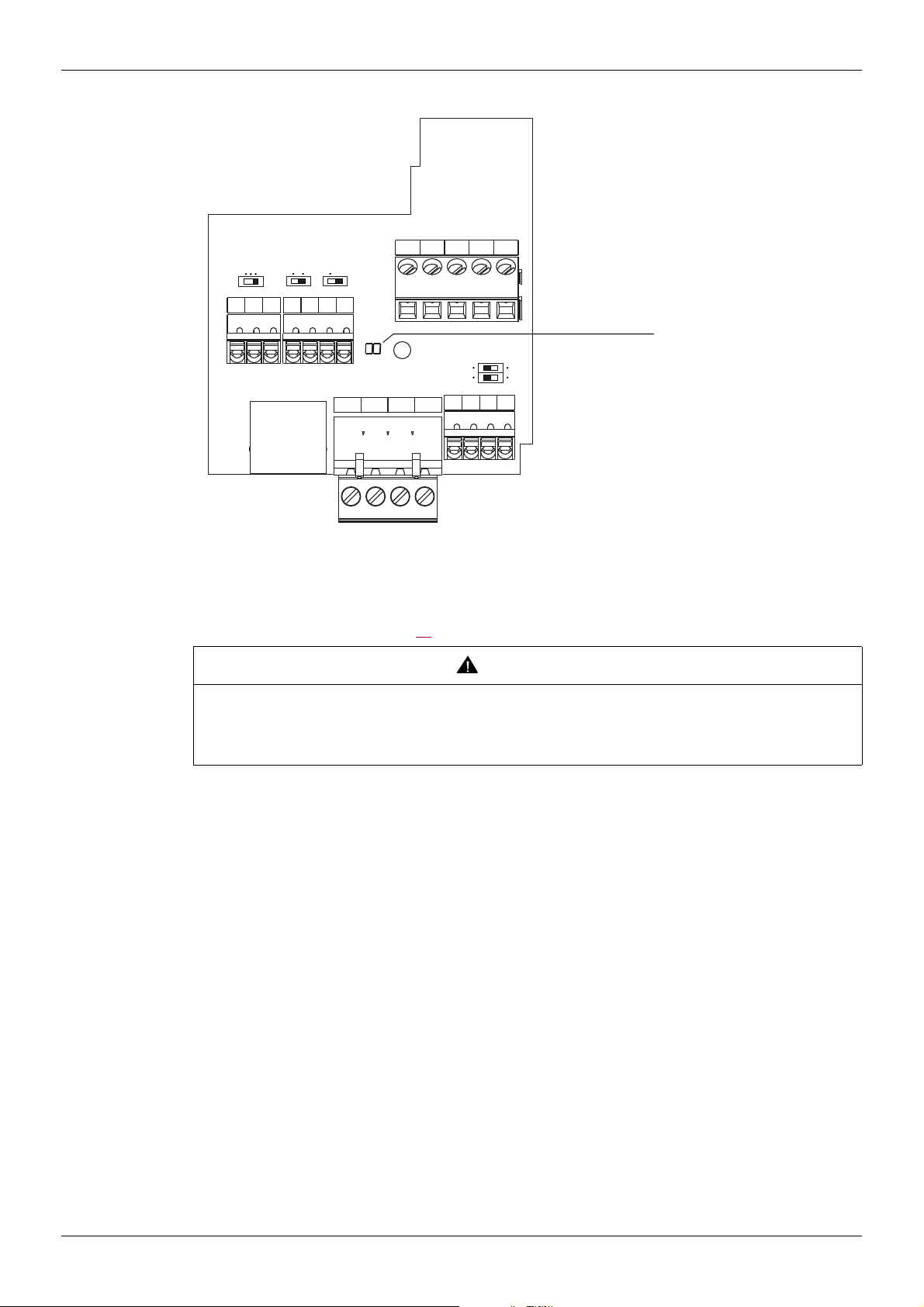
Hardware description
Open Style Connector
RJ45
PLC FM
Sink
SW102
FR
Source
SW101
RES PLC P24
IU
Term
SW103
CC FM
FLA
FLB FLC RYA RYC
Hardware
Diagnostic LEDs
Use of open Style Connector
Use the open style connector to connect the drive to BACnet fieldbus. Full connection details are given in the
Connecting to the bus section page 19.
UNANTICIPATED EQUIPMENT OPERATION
• Modify only the setting of the switches when the product is switched off.
• Do not change the setting of the SW102 unless your system is wired for SINK logic.
Failure to follow these instructions can result in death, serious injury, or equipment damage.
BAGNDSCR
SW100
I
PTC
VIA U
VIB U
PP CCVIA VIB
WARNING
12 S1A53845 04/2017

Hardware
F, R, RES
SINK
SOURCE
PP
+24V
(1)
VIA
15k
15k
250k
300k
U
I
RYA
RYC
FLA
FLB
FLC
Description of terminals
Terminal
symbol
Function Electrical specifications Internal circuits
Multifunctional programmable logic input.
F
It has forward rotation function in default setting.
ON: forward rotation drive
OFF: slowdown and stop
R
RES
Multifunctional programmable logic input.
It has Preset speed command input 1 in default setting.
Multifunctional programmable logic input.
It has Fault Reset in default setting
PP Voltage supply for reference potentiometer.
Switch-configurable voltage or current analog input using
SW100.
VIA
It has speed setpoint function in the default setting. (0 to 50
Hz frequency with 0 to 10 Vdc in voltage or with 0 to 20 mA
in current input). In addition,This analog input is also
configurable as a logic input.
Input for voltage-free contact
24 Vdc, 5 mA or less.
SINK/SOURCE can be selected with
SW102.
Voltage: 10 Vdc
Max current: 10 mA
Protected against short circuits.
Voltage: 10 Vdc
Internal impedance: 30 k
Current: 0 - 20 mA
Multifunction programmable analog input.
It has speed setpoint function in the default setting
VIB
(0 to 50 Hz frequency with 0 to 10 Vdc input). In addition,
this terminal can be used as PTC (2) input by setting switch
Voltage: 10 Vdc
Internal impedance: 30 k
SW100 and the parameters [Mot PTC selection] F645
and [PTC resistor value] F646.
CC Control circuit equipotential terminal -
This terminal is only active when the switch (SINKSOURCE) is on PLC position. It allow to manage external
PLC
sink or source with static outputs. PLC shall be connected
Max. voltage: 50 Vdc
to 0V (CC terminal) or +24V according to the type of
outputs
P24 24 Vdc power supply output Voltage: 24 Vdc, 50 mA
Voltage analog output: 0...10 Vdc
FM
Switch-configurable voltage or current analog output using
SW101.
Minimum load impedance: 470
Current analog output: 0...20 mA
Maximum load impedance: 550
FLA
FLB
FLC
RYA
RYC
Multifunctional programmable relay contact outputs.
Default setting is set to detect the activation of the drive
protection function.
Contact across FLA-FLC is closed and FLB-FLC is open
during normal operation. RYA -RYC is open.
Voltage: 30 Vdc, 0.5 A
250 Vac, 1A
(cos
= 1)
Voltage: 250 Vac, 0.5A
(cos
= 0.4)
(2)
(1) Voltage conversion
(2) PTC (Positive Temperature Coefficient): Resettable thermal fuse resistor for over current protection.
S1A53845 04/2017 13

Hardware
Terminal
symbol
B
A
GND
SCR
Function Electrical specifications Internal circuits
BACnet open style connector
RS485 transmission data, reception
data.
BACnet communication shield terminal.
This terminal is not connected to other circuits in the board.
Ground this terminal in a location separated from the ground of the power line.
GND
SCR
4.7k
B
A
4.7k
TERM
SW103
47k
47k
120
14 S1A53845 04/2017
 Loading...