


DC09

INSTALLATION
MANUAL
©
Scania CV AB 2016, Sweden
03:10 Issue 6.0 en-GB 1
Fault codes DM1
Industrial engines
DC09, DC13, DC16
Marine engines
DI09, DI13, DI16
INSTALLATION
MANUAL
©
Scania CV AB 2016, Sweden
03:10 Issue 6.0 en-GB 2
DM1 ..........................................................................................................................3
Abbreviations...........................................................................................................3
Fault type identifier................................................................................................. 3
List of fault codes.....................................................................................................4

INSTALLATION
MANUAL
©
Scania CV AB 2016, Sweden
DM1
03:10 Issue 6.0 en-GB 3
DM1
Fault codes generated in the CAN network are sent via CAN message DM1. This
document describes how to interpret these fault codes from the DM1 message.
Abbreviations
Fault type identifier
Explanation of FMI codes.
Abbreviation Explanation
SPN Suspect Parameter Number
FMI Failure Mode Identifiers
Code Explanation Code Explanation
0 Data valid but above normal operational range (that is, engine overheating) 12 Bad intelligent device or component
1 Data valid but below normal operational range (that is, engine oil pressure too low) 13 Out of calibration
2 Data erratic, intermittent, or incorrect 14 Special instructions
3 Voltage above normal or shorted high 15 Data valid but above normal operating range - least severe level
4 Voltage below normal or shorted low 16 Data valid but above normal operating range - moderately severe level
5 Current below normal or open circuit 17 Data valid but below normal operating range - least severe level
6 Current above normal or grounded circuit 18 Data valid but below normal operating range - moderately severe level
7 Mechanical system not responding properly 19 Received network data in error
8 Abnormal frequency, pulse width, or pending 20 Data drifted high
9 Abnormal update rate 21 Data drifted low
10 Abnormal rate of change
11 Failure mode not identifiable
INSTALLATION
MANUAL
©
Scania CV AB 2016, Sweden
List of fault codes
03:10 Issue 6.0 en-GB 4
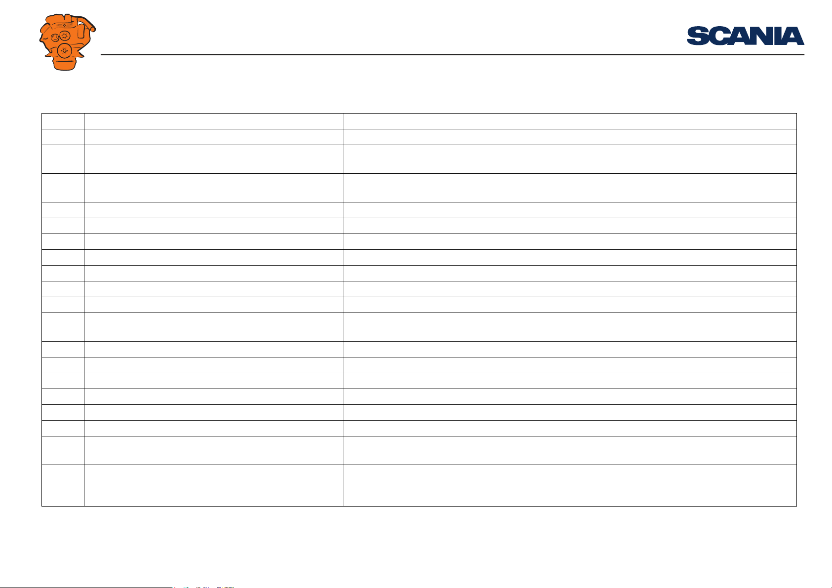
List of fault codes
SPN SPN Name SPN Description
46 Pneumatic Supply Pressure The pneumatic pressure in the main reservoir, sometimes referred to as the wet tank.
51 Engine Throttle Valve 1 Position The position of the valve used to regulate the supply of a fluid, usually air or fuel/air mixture, to an en-
gine.
91 Accelerator Pedal Position 1 The ratio of actual position of the analogue engine speed/torque request input device (such as an accel-
erator pedal or throttle lever) to the maximum position of the input device.
94 Engine Fuel Delivery Pressure Gage pressure of fuel in system as delivered from supply pump to the injection pump.
97 Water In Fuel Indicator Signal which indicates the presence of water in the fuel.
98 Engine Oil Level Ratio of current volume of engine sump oil to maximum required volume.
100 Engine Oil Pressure Gage pressure of oil in engine lubrication system as provided by oil pump.
102 Engine Intake Manifold #1 Pressure The gage pressure measurement of the air intake manifold.
103 Engine Turbocharger 1 Speed Rotational velocity of rotor in the turbocharger.
105 Engine Intake Manifold 1 Temperature Temperature of pre-combustion air found in intake manifold number 1 of engine air supply system.
107 Engine Air Filter 1 Differential Pressure Change in engine air system pressure, measured across the filter, due to the filter and any accumulation
of solid foreign matter on or in the filter.
108 Barometric Pressure Absolute air pressure of the atmosphere.
110 Engine Coolant Temperature Temperature of liquid found in engine cooling system.
111 Engine Coolant Level Ratio of volume of liquid found in engine cooling system to total cooling system volume.
131 Engine Exhaust Back Pressure
132 Engine Intake Air Mass Flow Rate Mass flow rate of fresh air entering the engine air intake, before any EGR mixer, if used.
156 Engine Injector Timing Rail 1 Pressure The gage pressure of fuel in the timing rail delivered from the supply pump to the injector timing intake.
167 Charging System Potential (Voltage) Electrical potential measured at the charging system output. The charging system may be any device
charging the batteries.
168 Battery Potential/Power Input 1 This parameter measures the first source of battery potential as measured at the input of the ECM/actu-
ator etc. coming from one or more batteries, irrespective of the distance between the component and the
battery.
 Loading...