


4Electrycal
Table of contents
 Loading...
Electrical system 11
© Scania CV AB 2003
1
ELECTRICAL SYSTEM ................................ 2
PROTECTION AND SAFETY
REQUIREMENTS ......................................... 3
Preventative measures.............................. 3
CONNECTORS ............................................. 4
Moisture-proof connectiors ...................... 4
POWER CONSUMPTION ............................. 5
SIZING FUSES AND CABLES AND
VOLTAGE LOSS........................................... 7
CENTRAL ELECTRIC UNIT ......................... 8
Extra central electric unit (accessories/
bodywork) .................................................. 9
FACTORY-FITTED WIRING........................ 10
Factory-fitted wiring in cab ..................... 11
Factory-fitted wiring for FM/AM radio ....13
Factory-fitted wiring for CB radio .......... 13
Factory-fitted wiring for cell phone........ 13
Factory-fitted extra voltage converter
24/12 V ...................................................... 13
Factory-fitted wiring for electrically
operated rear-view mirrors ..................... 13
Connecting extra lights ........................... 14
Power socket in cab ................................ 14
Extra direction indicators ....................... 14
Extra brake light lamps ........................... 14
Electrical items for front-mounted
equipment ................................................ 15
EXTRA CONTROL BOX ............................. 17
JUNCTION BOX IN FRAME ....................... 18
PLACE FOR OPTIONAL ELECTRICAL
ACCESSORIES IN TOPLINE CAB ............ 19
POWER TAKE-OFFS IN COMBINATION
WITH OPTICRUISE .................................... 20
EDC ............................................................. 21
Hand throttle (normal) ............................. 22
Limited hand throttle ............................... 22
Raised idling speed ................................. 23
Fixed engine speed ................................. 23
Example of setting three fixed engine
speeds ...................................................... 24
Torque limitation ...................................... 25
Speed limiter ............................................ 26
Engine stop .............................................. 26
External control of engine speed ........... 27
ADR............................................................. 28
Bodywork on ADR-equipped vehicle .....28
SWITCHES ................................................. 29
APPENDIX:
Wiring diagrams manual
Connection diagrams sheets 1-4
Contents

Electrical system 11
© Scania CV AB 2003
2
ELECTRICAL SYSTEM
This chapter provides general information about
the electrical system in the Scania 4 series which is
relevant to bodywork.
Supplementing this chapter as attachments are
Manual: Wiring diagram with list of components
and Basic electrical systems.
For further information about components,
diagrams, etc. contact a Scania dealer.
For further information concerning the illustration,
see the Manual: Wiring diagram attachment.

Electrical system 11
© Scania CV AB 2003
3
PROTECTION AND SAFETY
REQUIREMENTS
Preventative measures
When working on the electrical system
Detach the battery earth lead and fit a line fuse
between the negative battery terminal and the
chassis in order to avoid accidents in the case of
short circuit.
In and under the instrument panel, close to hot air
ducts, temperatures can reach 90 °C. Always use
cables which resist at least 105 °C in the cab.
Electronic control units and components for such
things as ABS, Opticruise and automatic gearboxes
can be sensitive to heat during oven drying after
painting and to current during such things as arc
welding. Prevent damage as follows:
When oven-drying
See Chapter 2 Painting
When arc welding
See Chapter 2 General recommendations for
bodywork section Welding, general.
When charging
Vehicle system voltage must not exceed 30 volts.
This means that jump starting should only be
carried out using batteries in order to prevent a
voltage surge which could damage electronic
components.
Protection against transients
Solenoid valves can give rise to high transients
when the ignition switch is turned off. For this
reason, always use solenoid valves with transient
protection.
The electrical system can cope with transients up to
150 V.
Batteries
The batteries should be trickle-charged to avoid
deterioration while the vehicle is under bodywork
construction.
If the specific gravity of the electrolyte falls too
low, sulphation of the lead plates will result and lead
to a drastic reduction of battery life and capacity.
See Chapter 2 General recommendations for
bodywork section Batteries.
Electrical system 11
© Scania CV AB 2003
4
Many connectors have a double latching
mechanism for cable terminals.
It is important to release or secure the
double latching mechanism after
changing or adding connectors.
CONNECTORS
A standard electrical system contains about 200
connectors of different shape and material.
When working on the electrical system, changing
or adding components, it is important to use the
same types of connector in order to avoid the risk
of causing interference.
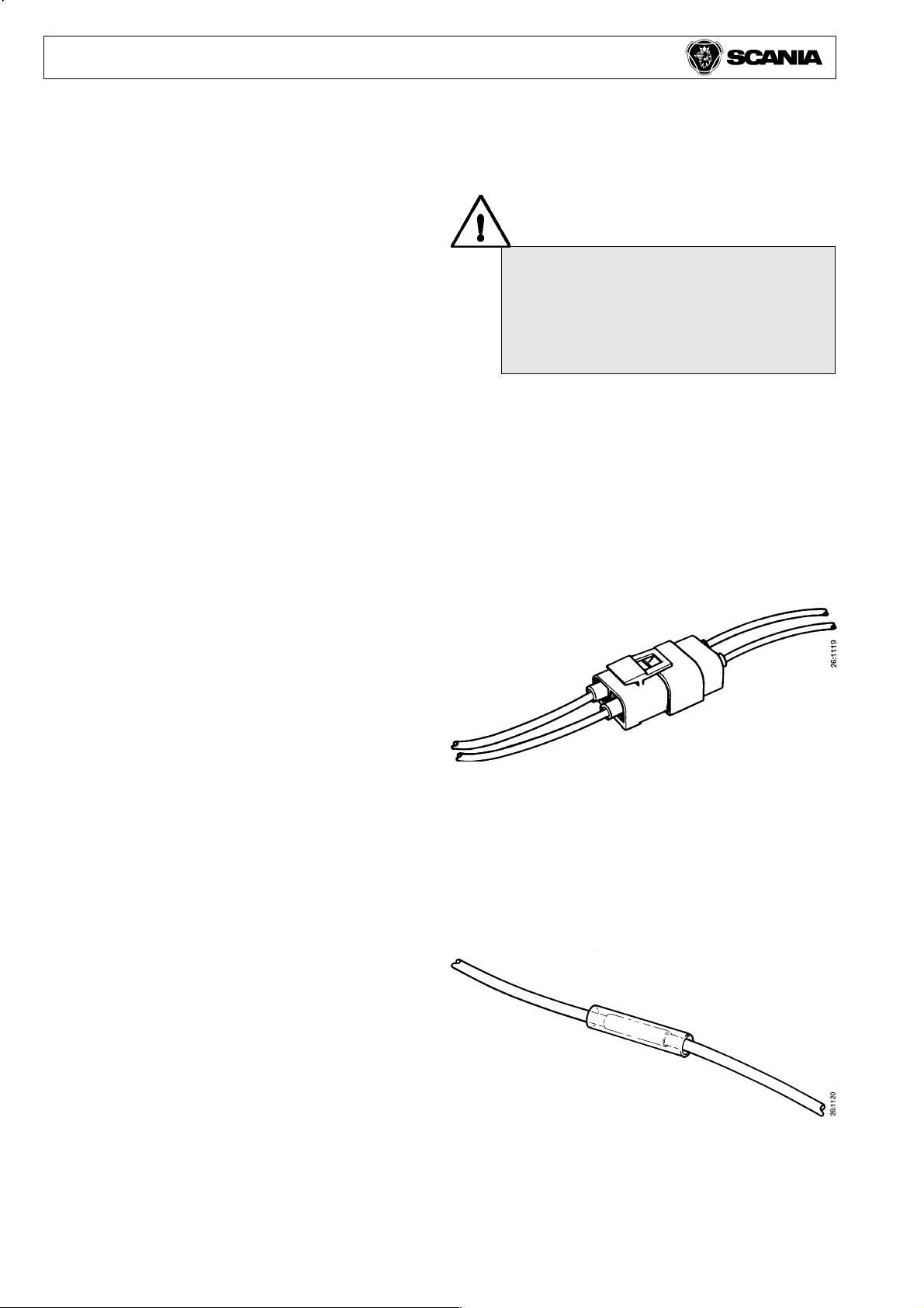
Moisture-proof connectiors
The Scania spare parts department can supply a
number of different types of moisture-proof
connector. Some examples are given below.
Moisture-proof, moulded connectors with 1 m of
1.5 mm
2
cable.
Part No.
389202 Female connector, 2-pole with cable
389203 Male connector, 2-pole with cable
1117327 Cable with female terminal, red
1117328 Cable with female terminal, black
1117329 Cable with male terminal, red
1117330 Cable with male terminal, black
Splice connector
Use splice connector part No. 341333 for splicing
cable 1-2.6 mm
2
. This is wound with vulcanising
tape part No. 380128 and cover tape part No.
380129.
Alternatively, use a splice connector with adhesive
lined heat shrink tubing.
Part No. 1112499 0.75 mm
2
1112500 2.5 mm
2
1112501 3-6 mm
2
Electrical system 11
© Scania CV AB 2003
5
Temperature is also important. A battery is much
less able to accept a charge at low temperatures. To
achieve charging balance the alternator should have
an overcapacity of about 15-25 A. In general, it
could be said that an overcapacity of about 15 A
suffices for a vehicle driven over long distances
without stopping (e.g. long-haul runs) while an
overcapacity of about 25 A is needed for a vehicle
making frequent stops (e.g. a delivery van).
To check whether the alternator has sufficient
capacity, obtain the total current consumption using
the tables below and then add the overcapacity.
Note that this is a very approximate calculation.
Engine speed
Alternator
(rpm)
65A
(A)
90A
(A)
500 30 42
600 40 58
700 46 68
800 50 76
1000 56 82
1200 60 88
1600 64 92
POWER CONSUMPTION
Batteries, alternator and current consumption must be
matched to each other. There should be a charging
equilibrium.
Alternator capacity should be matched to current
consumption so that battery damage is avoided.
The time aspect is important. The current taken from
the batteries must restored within a day or two.
What is the driving cycle like? Frequent starting and
lengthy idling periods will not charge up the batteries
as efficiently as long-haul runs. The alternator genera-
tes less current at low engine speeds.
Some examples are given below.
Electrical system 11
© Scania CV AB 2003
6
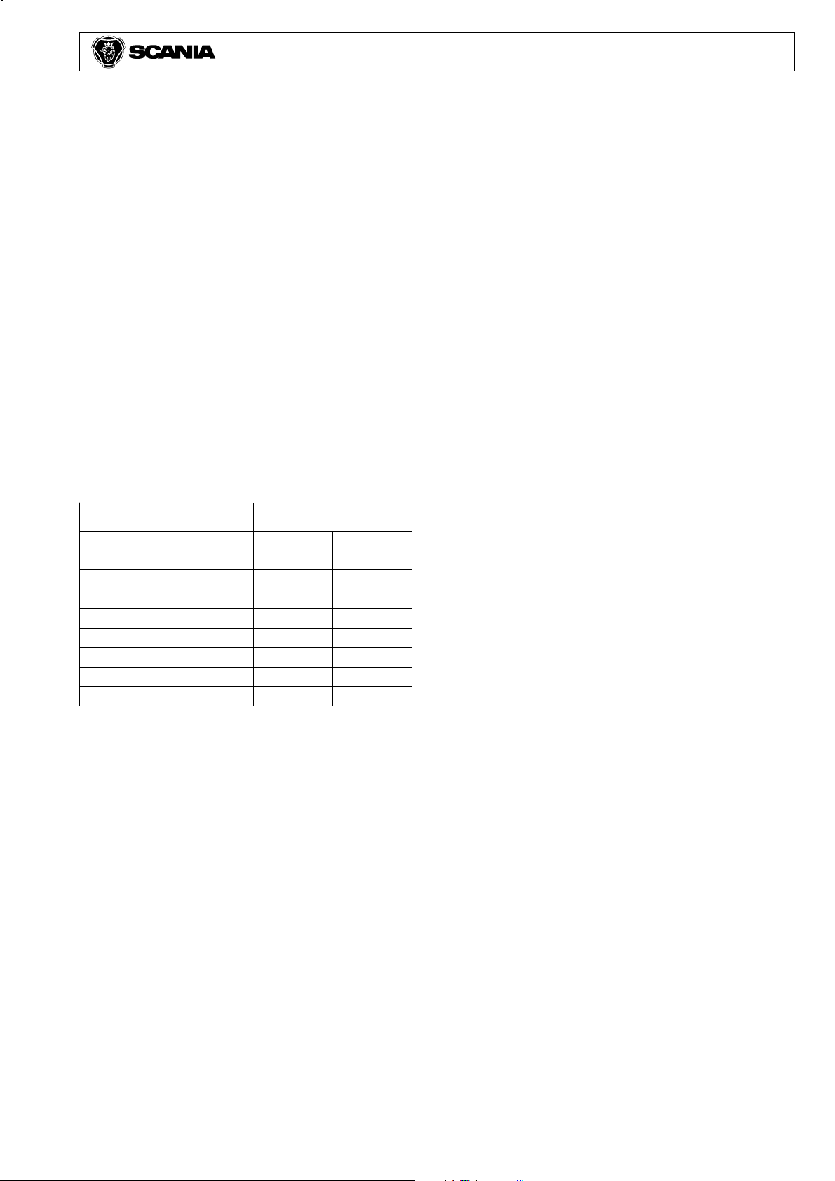
Guide values for extra equipment
Operating
time
Extra lights 2-4 x 3 A = 6-12 A 50%
Side marker lights 4-6 x 0.5 A = 2-3 A 100%
Roof lighting, external 1 x 4 A = 4 A 50%
Loading lights 2 x 4 A = 8 A 50%
Electrically-heated seats 2 x 2.5 A = 5 A 25%
Electrically-heated mirrors 2 x 2 A = 4 A 25%
Refrigerator 1 x 2 A = 2 A 60%
Extra cab heaters: 25%
a) Engine cab heater (Webasto) = 6 A
b) Cab heater (Eberspächer) = 3 A
c) Short stop heater = 4 A
Retarder (Electric) 1 x 100-200 A = 100-200 A 5-10 %
Battery heater 1 x 10 A = 10 A 25-50 %
Tail lift 1 x 100 A = 100 A ----
Normal power consumption, truck
Electric fuel injection 1 x 5 A = 5 A
Main beam headlights 2 x 3 A = 6 A
Rear lights 4 x 0.25 A = 2 A
Front position lights 2 x 0.25 A = 0.5 A
Width marker lights 2 x 0.25 A = 0.5 A
Instrument illumination 20-30 x 0.05 A = 1.5 A
Fan motor 1 x 5 A = 5 A
Windscreen wipers 1 x 4 A = 4 A
Air dryer 1 x 3 A = 3 A
Radio ( std ) 1 x 2 A = 2 A
Normal power consumption, trailer
Rear lights 4 x 0.5 A = 2 A
Side marker lights 8 x 0.5 A = 4 A
Width marker lights 2 x 0.25 A = 0.5 A
Box interior lighting 4 x 2 A = 8 A
To avoid shortening the useful life of the batteries,
the radio position on the ignition switch should be
used whenever possible for supplying power. In the
drive position the entire electrical system is
engaged, which increases current consumption and
with it a bigger drain on the battery.
Electrical system 11
© Scania CV AB 2003
7
SIZING FUSES AND CABLES AND
VOLTAGE LOSS
If cables are long, it may be necessary to use a
thicker cable to reduce voltage loss.
Normally, a voltage loss of 5 % (1.2 V) is acceptable.
Voltage loss in copper conductors is calculated
using the following formula:
U = I x (0.0175 x L) / A
U = Voltage loss (V).
I = Current in amps (A).
L = Length of cable.
A = Cross-section of conductor (mm
2
).
Calculate how many amps are consumed when
extra equipment is connected in order to size the
fuses and cables.
Use the following equation:
I = P/U
I = Current in amps (A)
P = Power in watts (W)
U = Voltage (V)
If two of P, U and I are known, the third can be
calculated as follows:
U = P/I, I = P/U, P = U x I
Example
Power P = 200 W
Voltage U = 24 V
I = 200 W / 24 V = 8.3 A
The calculated total current through a fuse should
not exceed 60 % of the amp rating.
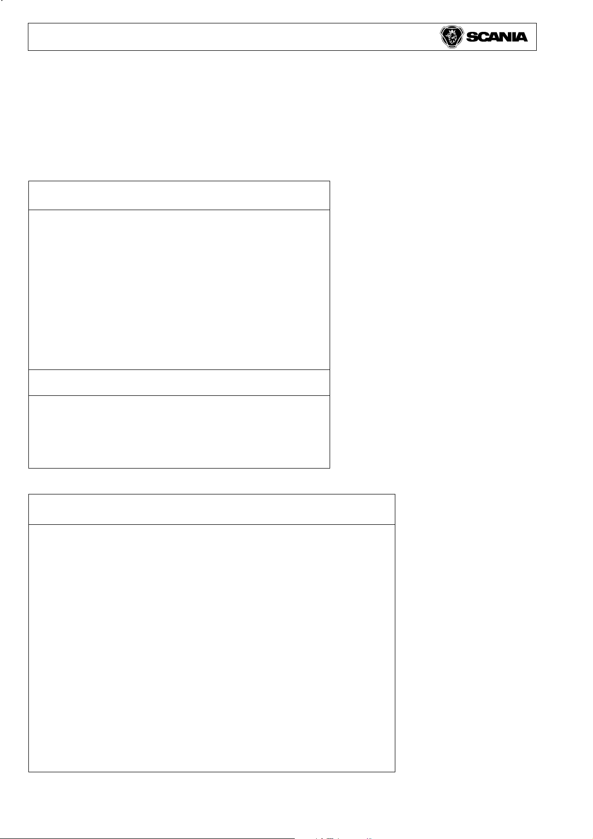
Sizing cables
Current, power and the distance to the load
determine the cross-section of the conductor.
Current Power Cross-section
10 A 200W 0.75-1 mm
2
15 A 400W 1.5 mm
2
20 A 500W 2.5 mm
2
25 A 650W 4.0 mm
2
40 A 850W 6.0 mm
2
50 A 1200W 10.0 mm
2
Cables outside the cab should be at least 1.5 mm
2
These values are based on the heat generated in the
cable with continuous current.
Always use the correct fuse. An
oversized fuse can cause fire in the
electrical system.
Electrical system 11
© Scania CV AB 2003
8
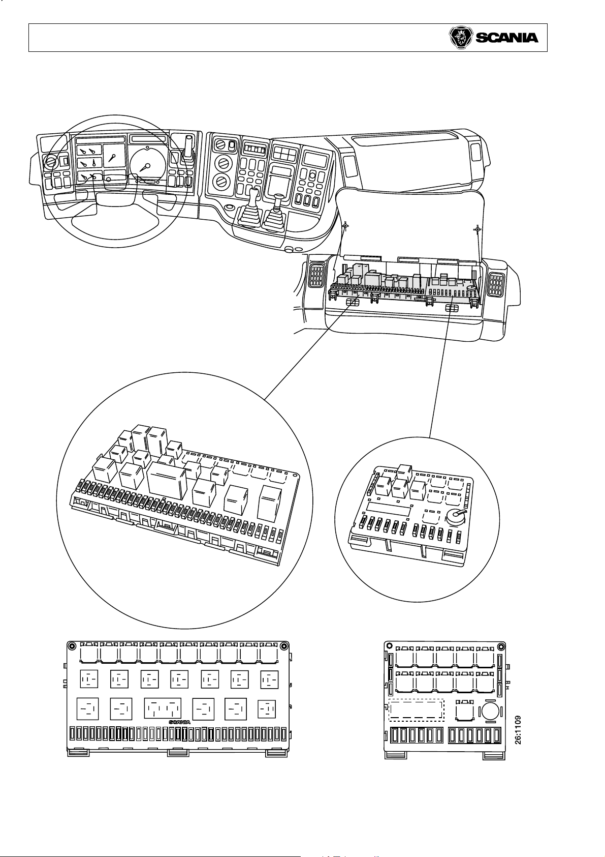
CENTRAL ELECTRIC UNIT
Central electric unit Extra central electric unit
(accessories/bodywork)
Electrical system 11
© Scania CV AB 2003
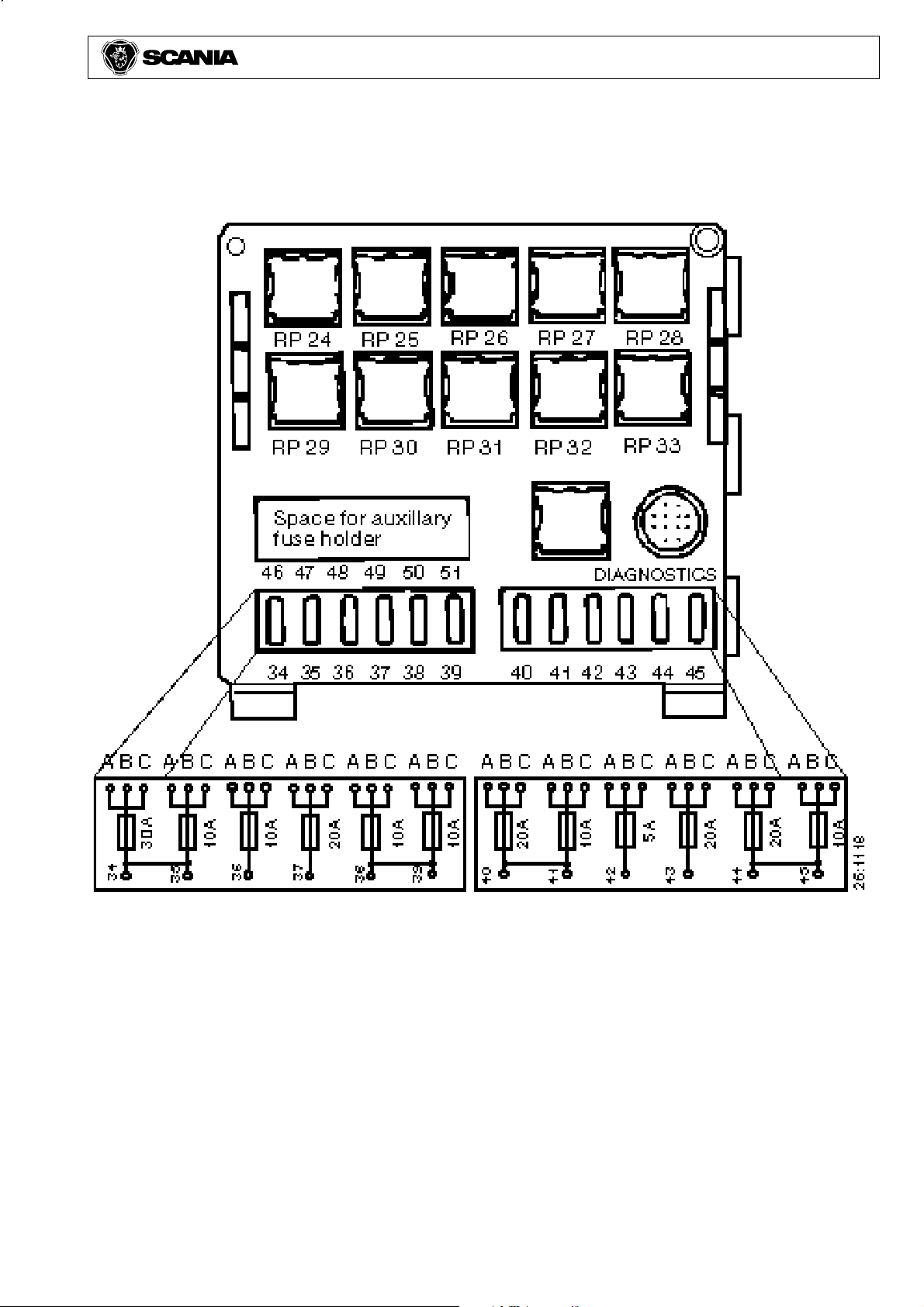
9
Extra central electric unit (accessories/bodywork)
The extra central electric unit can have a varying
number of positions occupied from factory,
depending on what extra equipment, such as fuel/
battery heater and flame start, is fitted.
Extra fuse holder for positions 46-51, part number
1320852.
Extra relay holder, 9-pole, part number 1320851.
Electrical system 11
© Scania CV AB 2003
10
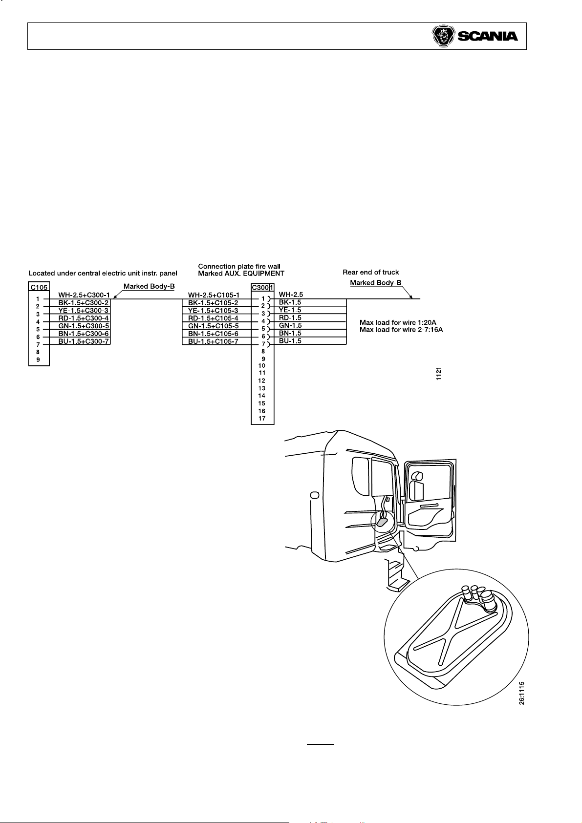
FACTORY-FITTED WIRING
With the exception of tractors, all vehicles can be
ordered with a seven-core cable running from the
cab to the rear end of the frame. Via a connector in
the bulkhead marked C300 this cable is wired to a
white connector marked C105 located under the
central electric unit and terminates without a
connector about 1 metre behind the junction box at
the rear end of the frame.
The cable is of ADR design on vehicles ordered
with ADR.
If the 7-core cable is not enough, or if it is
necessary to route cables to the cab of tractor units,
there are four lead-throughs of varying diameter in
the floor on the passenger side.
Cable lead-throughs
Note: The floor panel is illustrated upside
down to show the rubber plugs.
Cable cross- Colour Max. load
section area
1 2.5 mm
2
white 20 A
2 1.5 mm
2
black 16 A
3 1.5 mm
2
yellow 16 A
4 1.5 mm
2
red 16 A
5 1.5 mm
2
green 16 A
6 1.5 mm
2
brown 16 A
7 1.5 mm
2
blue 16 A
Suitable connector housing for C105: part. no. 813556
Suitable round female terminals
Cable cross-section: 1.5 mm
2
part no. 813925
Cable cross-section: 2.5 mm
2
part no. 813927
Loading...