


Electrical system in P, R, T
Table of contents
 Loading...
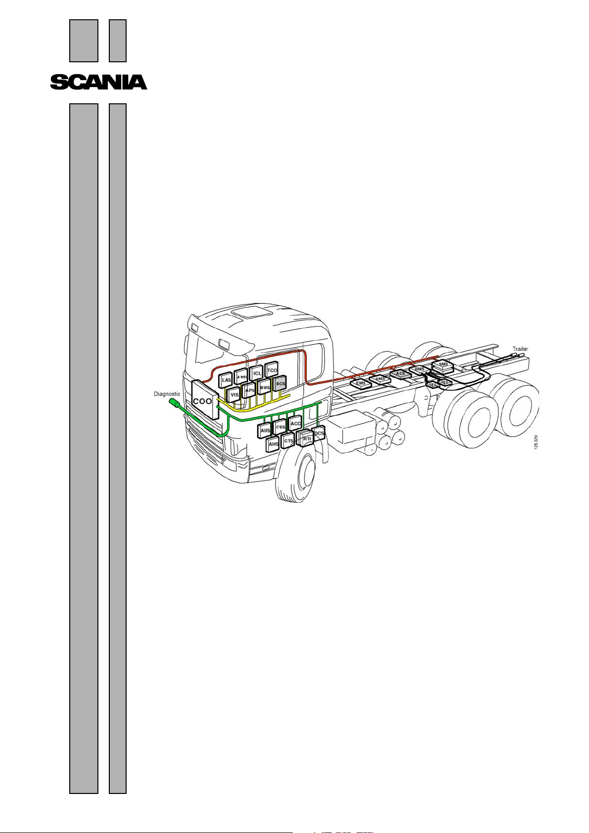
©
Scania CV AB 2005, Sweden
16:07-01
Issue 3 en
Electrical system in P, R, T series
Introduction and general
troubleshooting

2
©
Scania CV AB 2005, Sweden
16:07-01
Contents
Introduction .................................................................................. 3
Electrical system in P, R and T
series
.................................................................................. 4
DEC system .................................................................................. 6
ECU system .................................................................................. 7
CAN network Overload on the CAN buses ................................... 12
Activation of the control unit..................................12
Vehicle internal time............................................... 13
ECU settings........................................................... 14
Cable harness.......................................................... 15
Power supply .......................................................... 16
Positive supply........................................................ 18
Moulded cables....................................................... 19
Earthing ..................................................................20
Connectors.............................................................. 24
User functions ................................................................................ 26
Wiring Diagrams ................................................................................ 28
Central electric unit ................................................................................ 34
Repairing cables ................................................................................ 35
Troubleshooting ................................................................................ 40
Communication problems on the
CAN buses
................................................................................ 55
Abbreviations ................................................................................67

16:07-01
©
Scania CV AB 2005, Sweden
3
Introduction
The structure of the electrical system in P, R
and T series vehicles is described here in brief.
In comparison with previous series, the
electrical system is now made up to a greater
extent of a number of control units which
communicate with each other via a network.
This new platform for the electrical system
gives increased reliability and the ability to
more easily re-specify and troubleshoot the
electrical system.
A condition for being able to make use of the
benefits of the new network-based electrical
system is a knowledge of how the Scania
diagnostic tools should be used.
It is important to exercise care and accuracy
when handling connectors, cables and control
units, to ensure that system reliability is
maintained after troubleshooting and re-
specifying the vehicle.
Note: Always disconnect the battery earth lead
before doing any electric welding on the
vehicle. Connect the earthing cable of the
welding unit to the part to be welded, as close
to the welding area as possible. If the earthing
cable is connected in any other way, items such
as bearings or electronic components may be
damaged.
Note: Do not connect extra equipment to the
CAN cables. Overloading of these cables may
cause malfunctions.
4
©
Scania CV AB 2005, Sweden
16:07-01
Electrical system in
P, R and T series
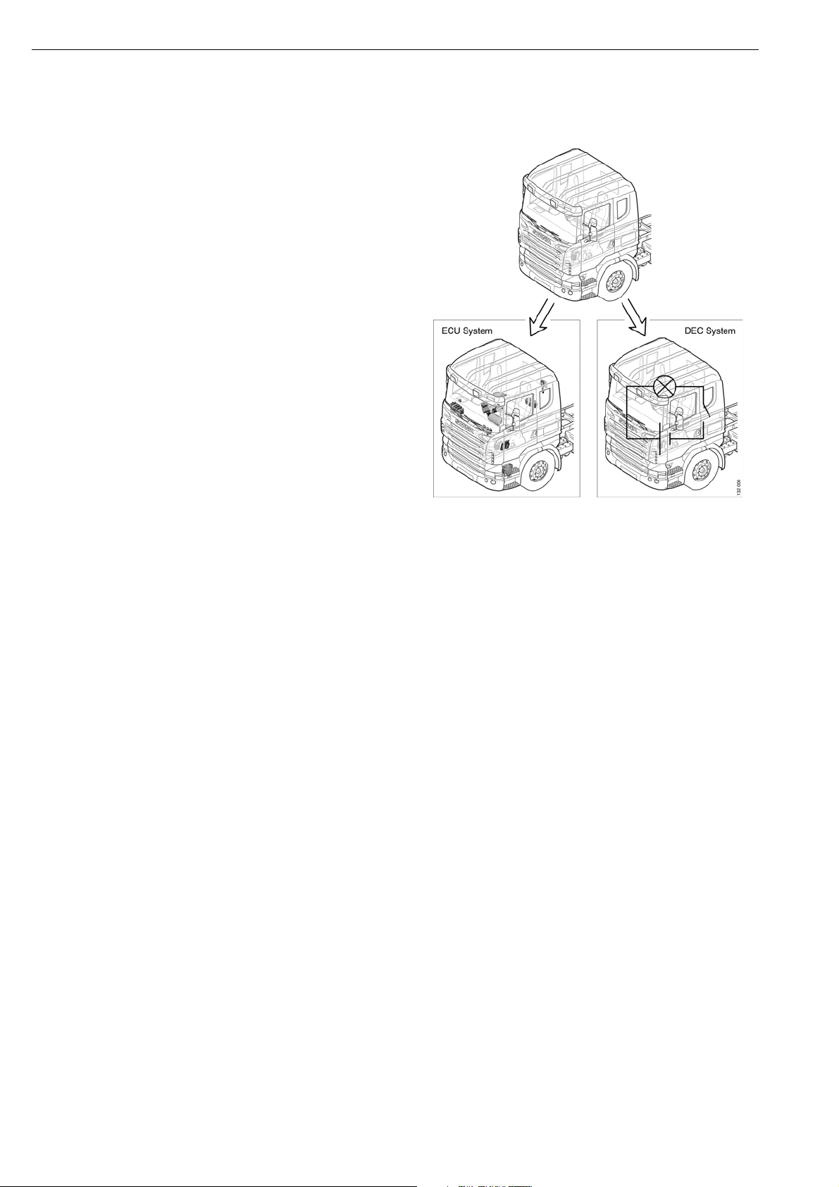
The electrical system on vehicles in the PRT
series has here been subdivided into the ECU
system (Electronic Control Unit) and the DEC
system (Discrete Electrical Circuit). The ECU
systems are controlled by an electronic control
unit, and they are connected to the CAN
network. The DEC systems can also be
controlled by an electronic control unit, but they
are not connected to the CAN network. Refer
also to Alternator and Starter motor in Multi and
the section on batteries in 16:06-41
16:07-01
©
Scania CV AB 2005, Sweden
5
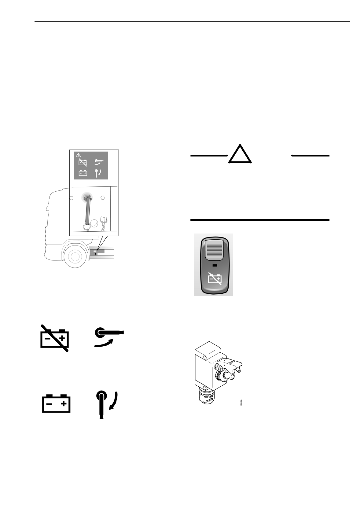
Battery master switch
The service switch is located by the battery box. Switch off the engine before disconnecting the
power. On vehicles with a safety switch the battery master switch is located on the instrument panel.
Some vehicles are also equipped with an exterior safety switch. When the battery master switch is
turned off, power is only supplied to the tachograph. Always disconnect the power in the vehicle
during servicing and work on the electrical system.
The service switch is located by the battery
box. Switch off the engine before disconnecting
the power.
Service switch turned off.
Service switch turned on.
!
WARNING!
When the battery master switch cuts off
the power, the engine stops. The
vehicle becomes difficult to control if
this occurs when moving. Stop the
vehicle, if possible, before cutting off
the power.
The safety switch for the battery master switch
is located on the instrument panel.
Exterior safety switch.
6
©
Scania CV AB 2005, Sweden
16:07-01
DEC system
There are around thirty sub-systems which are
not connected to the CAN network. These
systems are a part of the DEC system group.
Examples of DEC systems are the kitchen
module, seat heating and window winders.
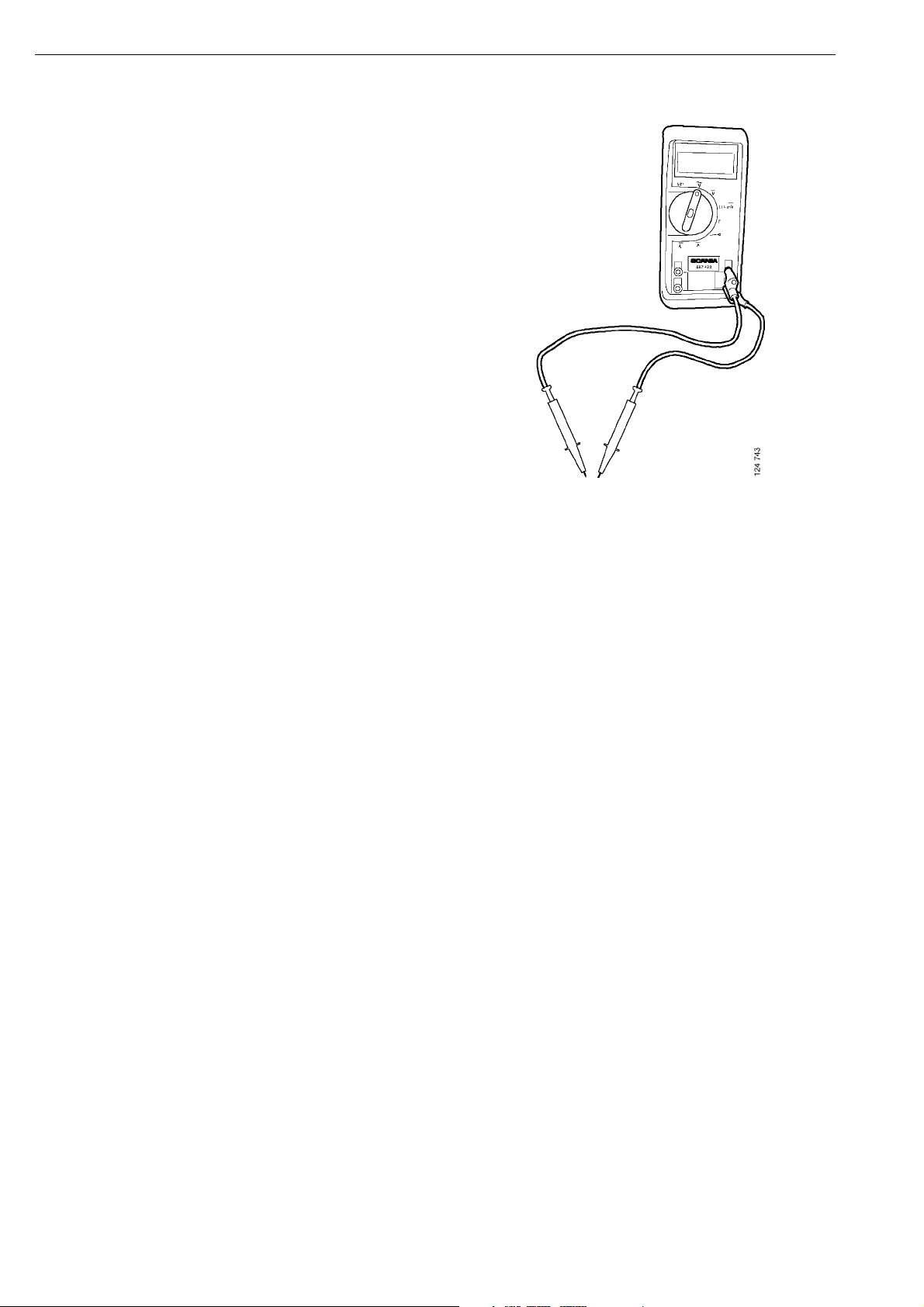
As the DEC system is not connected to the CAN
network, it is not possible to read any fault codes
from them using SDP3. All troubleshooting
should therefore be carried out in the normal
way using a multimeter.

16:07-01
©
Scania CV AB 2005, Sweden
7
ECU system
The electronic control units in the ECU systems
are programmed to continuously write specific
messages to the CAN network. They are also
programmed to read specific messages which are
written by other control units.
One advantage of connecting together control units
in a network is that both the driver and the
mechanic can obtain significantly more
information on the vehicle status and on any faults.
This makes troubleshooting both simpler and
faster. This is provided you have access to the
Scania diagnosis and programming tool (SDP3).
Furthermore, it enables the mechanic to change
functions in the ECU systems in a simple way by
changing the settings in the control units with
SDP3. If you do not have access to SDP3,
however, it will be more difficult to troubleshoot
compared to earlier vehicle series.
The CAN network on a high specification PRT
series vehicle can contain around 20 ECU systems.
On the simplest vehicles, however, there are only
five ECU systems (EMS, COO, VIS, APS and
ICL).
Several ECU systems in the PRT series were
controlled by an ECU also in the 4-series, and they
were linked together in a CAN network. This
applied to: BMS, EMS, GMS and RTG. Other
systems were controlled by an ECU, but were not
linked together in a CAN network. This applies to:
the radio (now: AUS), the auxiliary heaters with
control unit (ATA/WTA with CTS), the alarm
system (LAS), the air suspension (SMS) and the
tachograph (TCO). Finally, some systems have
been introduced whose functions were previously
controlled using conventional technology such as
relays. This applies to: ACC, APS, BWS, ICL and
VIS.
To reduce the risk of the CAN bus being
overloaded with messages, Scania has chosen to
divide the ECU systems between three CAN buses.
The ECU systems which are most important to
vehicle operation (BMS, COO, EMS and GMS)
are linked together on a CAN bus (red bus). The
other ECU systems are subdivided onto two CAN
buses which Scania calls the yellow and green bus.
Scania Diagnos is connected to the green bus.
In addition to these CAN buses, there can be
additional CAN buses. For example, some of the
units in the EBS system communicate through
an internal CAN.
It should be noted that ICL is connected to the
yellow CAN bus. Problems in this CAN bus
should not stop the vehicle. But if a problem
arises on the yellow CAN bus, this affects ICL
which is then unable to listen to the other CAN
buses and will then prompt the driver to stop
the vehicle.

8
©
Scania CV AB 2005, Sweden
16:07-01
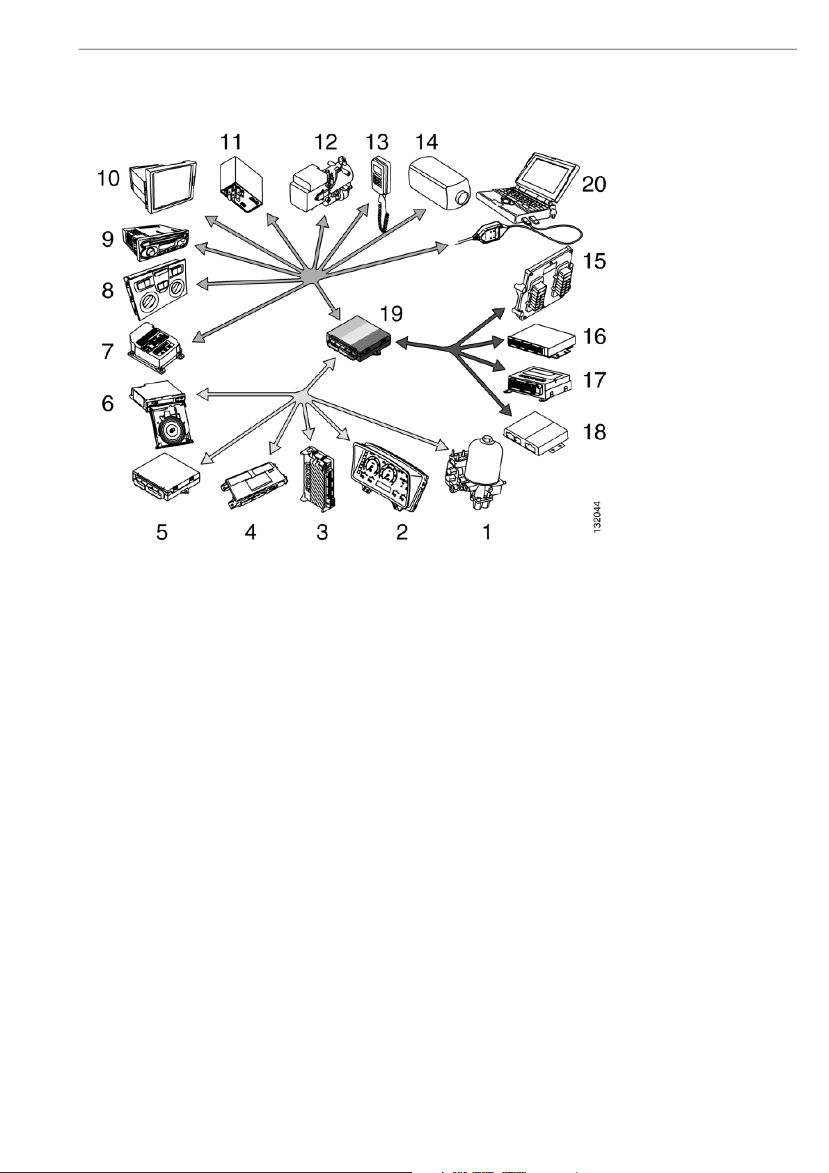
Example of functions in the CAN network
Function ECU designation CAN colour
1 Compressed air supply APS Yellow
2 Instrument cluster ICL Yellow
3 Lights, visibility and
horn control
VIS Yellow
4 Locks and alarm LAS Yellow
5 Bodywork interface BWS Yellow
6 Tachograph TCO Yellow
7 Crash safety, airbag CSS Green
8 Climate control ACC Green
9 Radio AUS Green
10 PC RTI Green
11 Vehicle data RTG Green
12,
13,
14
Auxiliary heater with
control panel
CTS. ATA. WTA Green
15 Engine management EMS Red
16 Brake BMS Red
17 Air suspension SMS Red
18 Gearbox and retarder
control
GMS Red
19 Coordinator COO Red
16:07-01
©
Scania CV AB 2005, Sweden
9
10
©
Scania CV AB 2005, Sweden
16:07-01
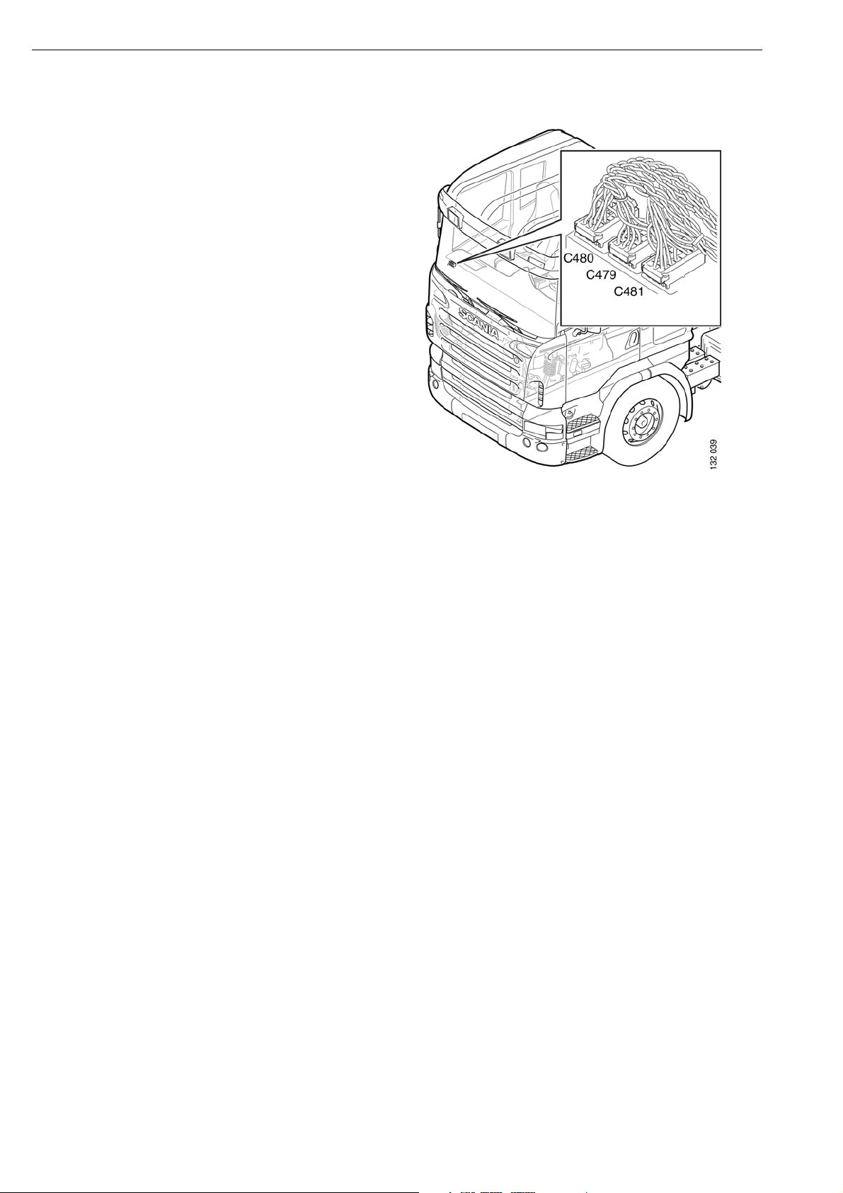
CAN network
To be able to troubleshoot in the CAN network,
it is important that you know about a number of
basic factors.
CAN technology has been developed to provide
a reliable transfer of data between different
components in the vehicle. It is based on serial
communication in two cables called CAN High
(CAN H) and CAN Low (CAN L).
The vehicle divides communication between
three CAN buses, red (C480), green (C479) and
yellow (481). This is to ensure good operation
and reliability.
16:07-01
©
Scania CV AB 2005, Sweden
11
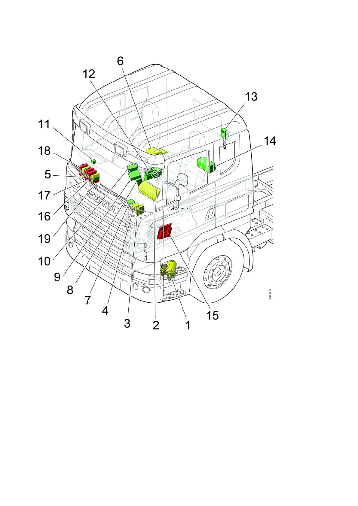
Location of control units in the cab
The illustration shows the basic location of the control units when the P series was introduced.
The control unit location may vary somewhat depending on the cab type and equipment level.
1 APS
2 ICL
3 VIS
4 LAS
5 BWS
6 TCO
7 CSS
8 ACC
9 AUS
10 RTI
11 RTG
12 WTA
13 CTS
14 ATA
15 EMS
16 BMS
17 SMS
18 GMS
19 COO
12
©
Scania CV AB 2005, Sweden
16:07-01
Overload on the CAN
buses
Faults can arise in ECU systems, resulting in the
systems continuously sending incorrect
messages to the extent that the communication
does not function. This is called overload.
Overload can result in some messages being
transmitted and others not. In turn, this means
that some functions will be missing. If the green
CAN bus is overloaded, this may also mean that
SDP3 cannot be used.
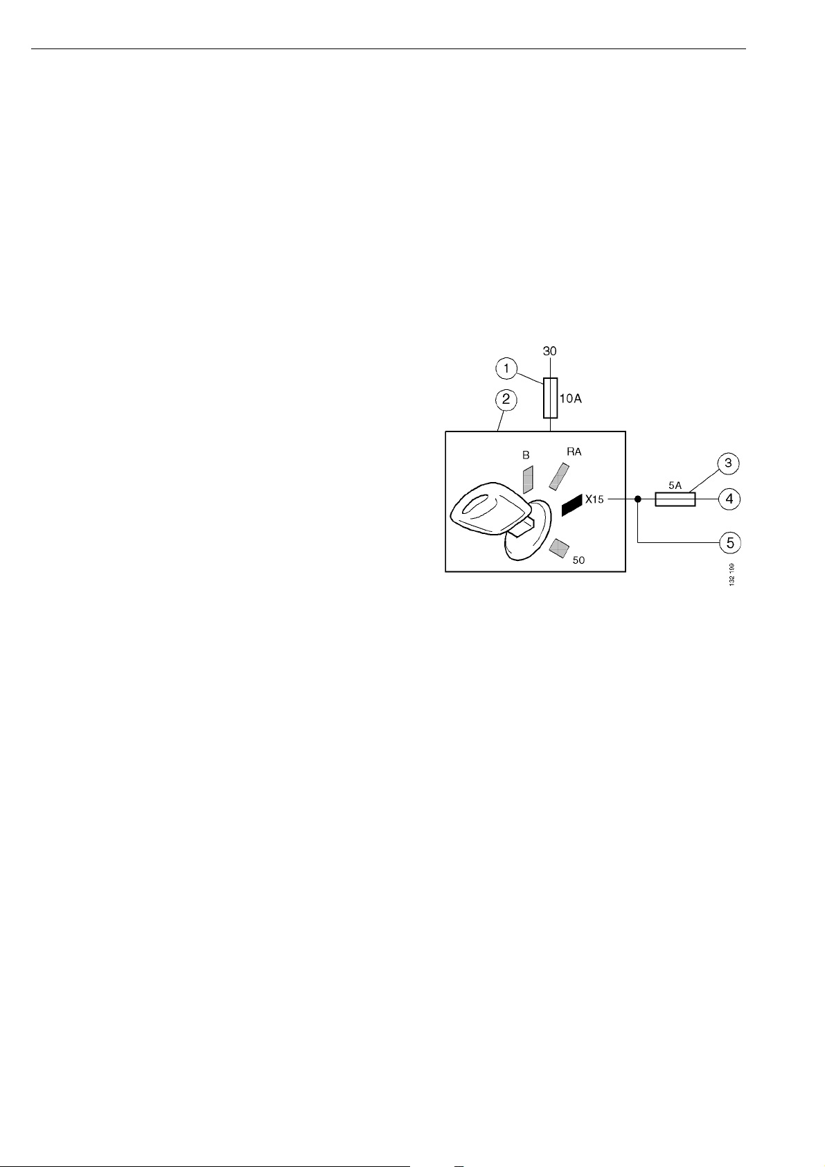
Activation of the control
unit
For a control unit (ECU) to be able to receive
CAN messages, it must have a power supply
from the battery (30-supply), and an activation
signal. The control unit is in most cases
activated by the starter key being turned to the
drive position (15-supply).
The starter lock (2) receives voltage from the
30-supply via a 10 amp fuse (1).
An X15-supply runs from the starter lock to the
CAN buses' control units.
To reduce the risk that control units on the red
bus (5) lose the 15-supply due to a fault on the
green or yellow buses (4), the control units on
the latter buses are protected by an additional
fuse (3).
16:07-01
©
Scania CV AB 2005, Sweden
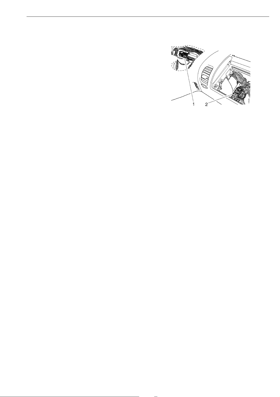
13
Connector C483, which supplies the control
units on the yellow and the green buses with
15-supply, is mounted centrally under the
instrument panel (1). Connector C482, which
supplies the red bus with 15-supply, is mounted
under the central electric unit (2).
There are, however, control units which are not
activated by the 15-supply, for example:
- LAS, which is active when the truck is
locked.
- AUS, which is activated as soon as the key is
in radio position.
- ATA/WTA is only activated after a command
from CTS/ACC.
Vehicle internal time
The vehicle internal time is independent from
the time the driver can see and change on the
instrument cluster (ICL).
The vehicle internal time is sent as a message
from the instrument cluster to other control
units. The vehicle internal time is used for
recording times of fault codes which are
generated by the control units. The vehicle
internal time can only be changed using SDP3.
Where a vehicle is equipped with a tachograph
(TCO), the ICL synchronises the vehicle
internal time with TCO internal time. In this
case, the vehicle internal time is set using the
special instrument which is used for setting the
TCO.

14
©
Scania CV AB 2005, Sweden
16:07-01
ECU settings
Scania manufactures vehicles with different
specifications. The vehicle model depends on
customer needs and requirements. For the
electrical system in a truck to work correctly,
the control units in the CAN network must be
adjusted so that they correspond to the vehicle
configuration (specification). For example, it is
crucial that the brake and suspension systems
are adjusted for the correct number of wheel
axles.
This adjustment is done during manufacture of
the vehicle, by setting a number of parameters
in the control units. These parameters, and
some other information, are written to a file
(the SOPS file), which is stored in COO and
ICL.
For some conversions, the SOPS file must be
changed if the vehicle is to function correctly.
The affected control units are then set using the
updated SOPS file. It is possible to make minor
changes to the SOPS file, such as after
changing to a fuel tank with larger volume,
using SDP3. More advanced changes, however,
may require the SOPS file to be sent to Scania.
COO continuously checks that certain safety
critical control units have not been renewed. If
an ECU is renewed, the new one must be
loaded with the correct parameters from the
SOPS file. This can also be done using SDP3.

16:07-01
©
Scania CV AB 2005, Sweden
15
Cable harness
With the introduction of the PRT series, Scania
has also introduced a new concept for earthing
electrical components. This concept will
provide more reliable and clearly arranged
earthing. Scania has also used a more limited
number of connector types for connections,
mainly for those connections located outside
the cab. The marking of the cables has also
been changed to make them more distinct.
Finally, the wiring diagrams have been changed
in a number of ways (see "Wiring Diagrams").

16
©
Scania CV AB 2005, Sweden
16:07-01
Power supply
The power supply system contains mainly the
components and cables that handle high
currents.
On PRT series vehicles, the electrical path
between the alternator and the batteries is
shorter in comparison with the 4-series. The
main advantage of this is that the total voltage
drop from the alternator to the batteries is less,
which means that more power can be fed to the
batteries.
The power supply system supplies all other
systems with a voltage supply and earth. This is
done via connections 15, 30, 12V/30, 12V/RA,
58 and 61. Each system may have one or more
connections.
The X designation is a new feature on the P, R,
and T series which has been introduced for
different cable functions. If a cable transmits
information, rather than a power supply, it is
marked with the prefix X. The activation signal
for the CAN bus control units X15 and the
power supply in drive position 15 are examples
of this.

16:07-01
©
Scania CV AB 2005, Sweden
17
Signal Function Type Direction Functional
source/destination
Physical
source/
destination
X15 Drive position Digital In Coordinator system Starter lock
X58 Relay Digital In Visibility system CUV
X61 Relay Digital In Visibility system CUV
XRA Radio Digital In Coordinator system Starter lock
XB Key inserted Digital In Coordinator system Starter lock
XRA
A
Radio Digital Out Coordinator system Voltage
converter
XBA Key inserted Digital Out Coordinator system Central
electric unit
15 Drive position Voltage supply Out Other system Central
electric unit
30 Battery
voltage
Voltage supply Out Other system Central
electric unit
12V/
30
Battery
voltage
Voltage supply Out Other system Voltage
converter
12V/
RA
Battery
voltage
Voltage supply Out Other system Voltage
converter
31 System
earthing
Earth - Other system
58 Parking lights Voltage supply Out Other system Central
electric unit
61 Charging
status
Voltage supply Out Other system Central
electric unit
Bodywork Voltage supply Out Bodywork interface
Tag axle lift Voltage supply Out Tag axle lift Junction
block
Visibility
system
Voltage supply Out Visibility system
Tachograph Voltage supply Out Tachograph system
Starter motor Voltage supply Out Starter motor
system
Junction
block
18
©
Scania CV AB 2005, Sweden
16:07-01
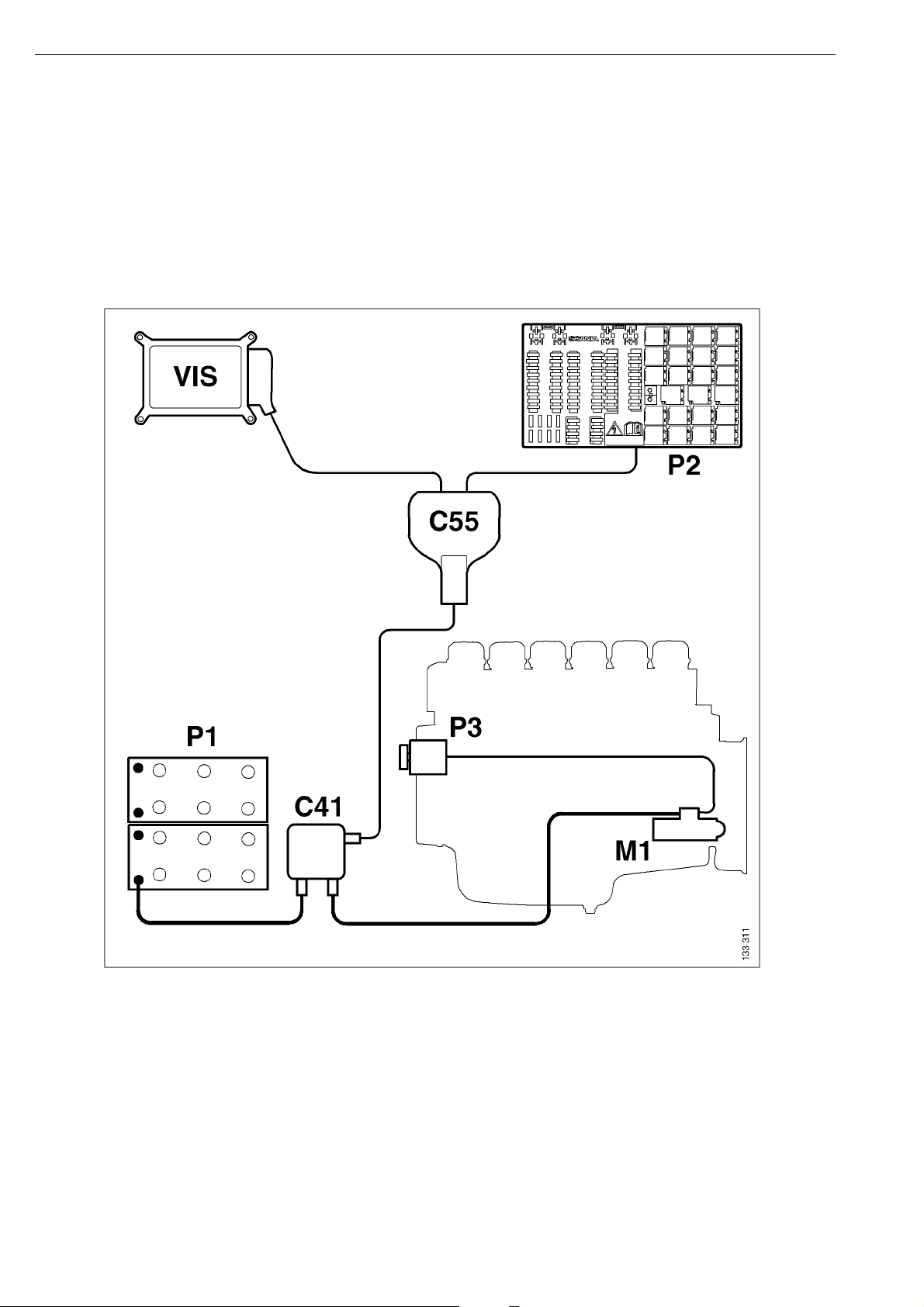
Positive supply
The power supply system has been simplified in the Scania vehicle range.
The cable from the alternator P3 goes via the starter motor M1 and a junction block C41 to the battery
P1. (A service switch is also fitted before the battery in most cases.) A cable goes from junction block
C41 to junction block C55 which provides a supply for the central electric unit P2 and visibility
system VIS.
Schematic diagram of the power supply
16:07-01
©
Scania CV AB 2005, Sweden
19
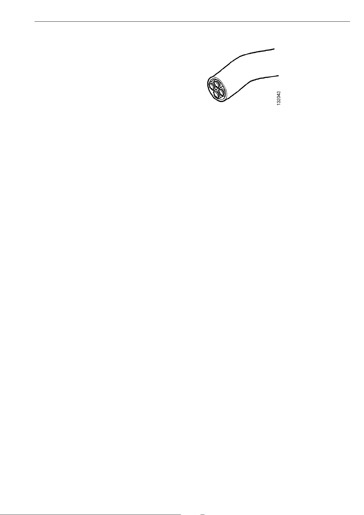
Moulded cables
Moulded cables are cables comprising several
individual wires with an inner and a common
outer sheath of polymer. The proportion of
moulded cables on the chassis is greater on the
PRT series than on the 4-series. This reduces the
risk of open circuits and short circuits caused by
chafed sheaths. Scania has also produced a new
range of moulded cables with thinner sheaths.
This is to make the cable harness in the frame
member easier to handle.
Note that the colours of the moulded cables do
not always agree with the colours of the
corresponding individual leads inside the cab.
20
©
Scania CV AB 2005, Sweden
16:07-01
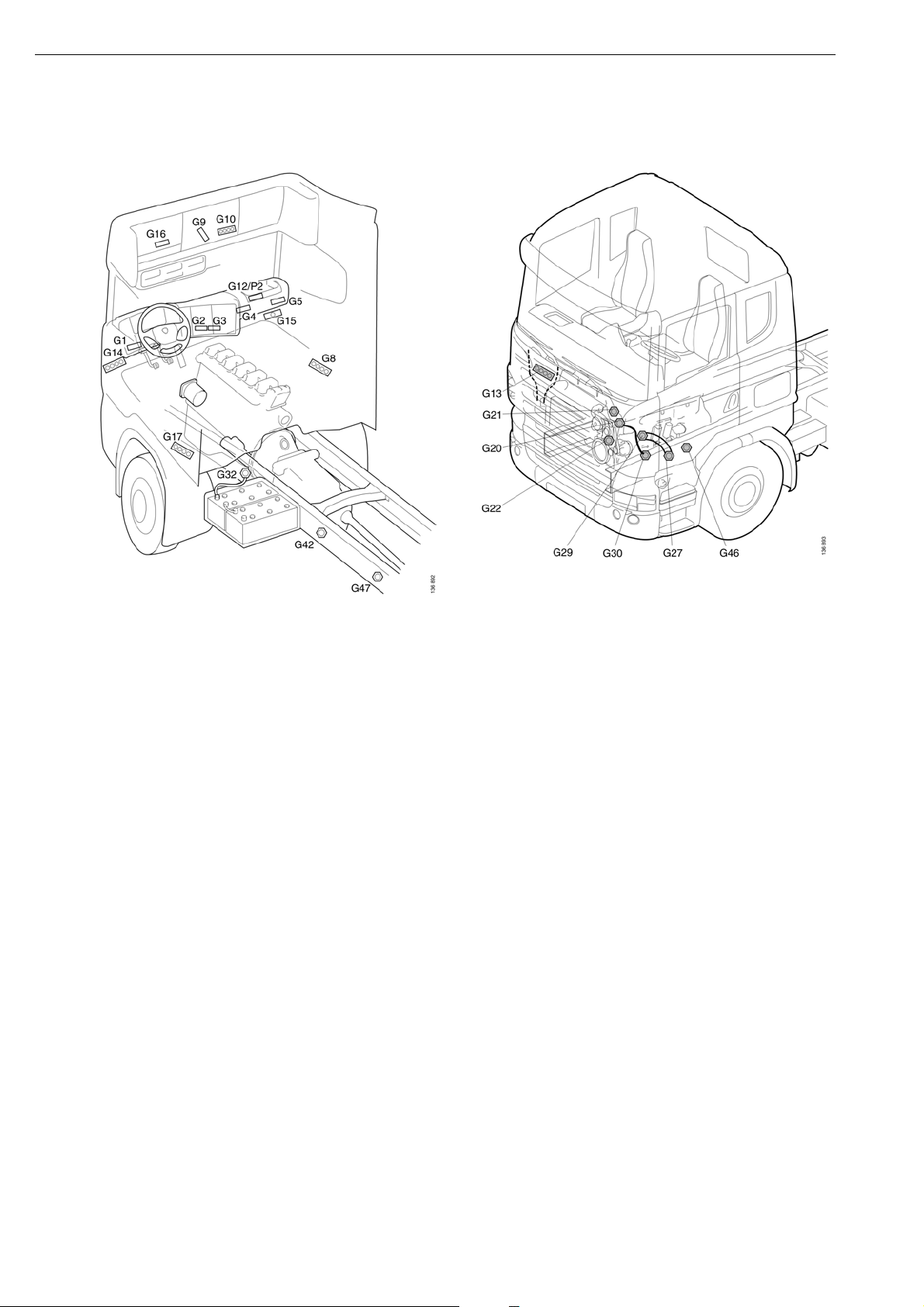
Earthing
The main earthing lines are the left-hand frame member, engine and gearbox block, and the cab
structure. To improve contact with the frame member, Scania has introduced a new earth bolt that is
pressed firmly into the frame member. Scania has also introduced special earthing points on the frame
for bodybuilders (G46 and G47).
Most of the components on and behind the instrument panel are earthed to one of the 21-pole earthing
blocks (G1-G5) that are distributed behind the instrument panel. From each of these blocks a common
cable runs to earthing points in the cab structure (G10, G14, G15). The earth cables are connected to
these earthing points with ring terminals. The most important components and the components
consuming most current are earthed directly to these earthing points. These earthing points can be
found e.g. in the roof and the lower part of the A-pillars.
16:07-01
©
Scania CV AB 2005, Sweden
21
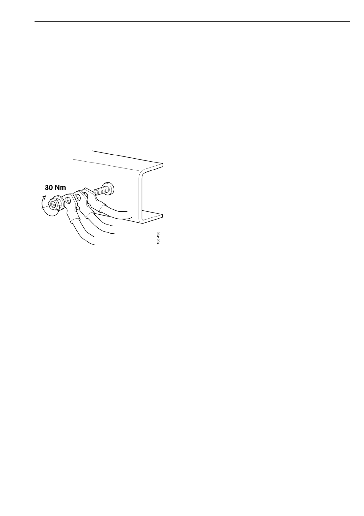
Fitting the frame earth bolt
A maximum of three ring terminals should be
connected to avoid an overload on the earthing
point. If you need to connect more ring
terminals, you must fit more earthing points.
Earth connection nut, part number: 815133
A maximum of three ring terminals may be
connected to each earth bolt. At least 1 turn of
the bolt thread should be visible on the
tightened joint. The earth connection nut is
tightened to 30 Nm using a hand tool.
Fitting the frame earth bolt
If the earth bolt has broken or provides a poor
contact with the vehicle, it must be renewed.
Contact is provided between the grooves in the
bolt and the frame member.
Note that the quality of the hole is crucial for a
good electrical connection. Therefore any rust
or paint in the hole must be removed before a
new earth bolt can be fitted.
The hole must be checked before a new earth
bolt is fitted, regardless of whether you are
using the old hole or drilling a new one. If the
hole is not within the tolerances, 14.2 mm
±0.1 mm, a new hole must be drilled.
If a new hole has to be made, it should be
drilled/reamed in stages up to the final
diameter.
It is important for the hole to be made at right
angles to the frame and for the hole to be as
cylindrical as possible.
22
©
Scania CV AB 2005, Sweden
16:07-01
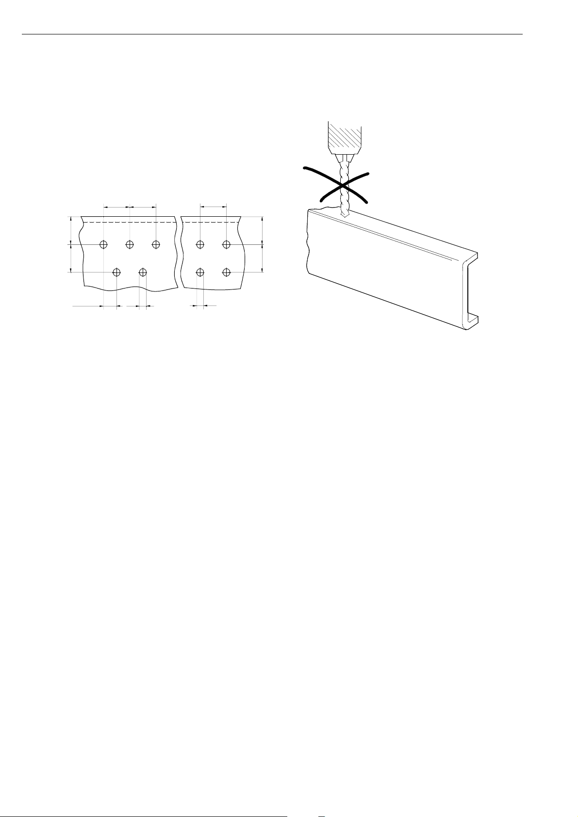
Drilling holes
The pre-drilled holes should be used whenever
possible.
If new holes have to be drilled closer to an
existing hole than the picture shows, the
existing holes should be welded closed, refer to
the Bodywork Manual.
A. Distance hole - frame flange should be at
least 3 x D and also at least 40 mm.
B. Minimum 4 x D.
C. Minimum 3 x D.
B B
A
C
B
A
B
D
D
B/2
b129114
IMPORTANT! It is not permitted to drill holes
in the frame flanges.
Holes are only to be drilled in the web of the
side members. The strength and service life of
the frame can be drastically affected by an
incorrectly positioned hole. The only
exceptions to this are holes drilled in the front
part of the frame and in the rear overhang in
areas where the loads are low.
b129113
Loading...