


Retarder
Table of contents
 Loading...
0
88
10:05-08
Issue 1
Scania Retarder
Troubleshooting
Mechanical system and hydraulic system
en
1 712 029
:22
1
©
Scania CV AB 1999, Sweden

Contents
Contents
Before starting troubleshooting
Troubleshooting
Test report
General............................................................ 3
Road test .........................................................4
Renewing components.................................... 4
Poor braking.................................................... 5
External oil leakage ...................................... 23
Cover for temporarily blocking the
retarder shaft output on the gearbox............. 27
Test report for test of
proportional valve......................................... 28
Test report for test of
hydraulic pressure......................................... 28
Valve housing and retarder housing ............. 30
2
©
Scania CV AB 1999, Sweden
10:05-08 en

Before starting troubleshooting
Retarder
Before starting
troubleshooting
General
The same retarder is used in trucks and buses
but the installation differs with respect to the
location of the oil cooler and accumulator, for
example. These troubleshooting instructions
apply to trucks and two-axle buses. Three-axle
buses are covered where applicable.
This description covers the troubleshooting
procedure for the retarder itself. The objective
is to determine whether dismantling is
necessary or not.
Troubleshooting the auxili ary brake system can
also be achieved with the help of the diagnostic
lamp marked Retarder on the vehicle's
diagnostic panel.
Spot repairs are often sufficient to make the
vehicle operable again.
All work on the retarder must be carried out
with the most thorough cleanliness possible.
The retarder is extremely sensitive to
impurities.
WARNING!
!
Hot fluid and coolant can cause
personal injury. This applies also to
spot repairs.
Wiring and similar components are often the
cause of a fault rather than the retarder.
Therefore, always start by checking for fault
codes.
Troubleshooting the entire auxiliary brake
system, i.e. with accompanying controls and
electrical equipment, is best achieved using
SD.
1050t14b.mkr
©
Scania CV AB 1999, Sweden
3

Before starting trouble shooting
Road test
The following applies when road testing the
vehicle to check, for example, whether a spot
repair has given the desired result.
1
Drive the vehicle at a speed of at least
60 kph
2
Select a gear so that the engine speed is at
least 1500 rpm.
3
Brake with the retarder lever in position 5,
max position.
If retarder braking capacity is still insufficient,
there is still a fault somewhere. Continue with
the troubleshooting as directed.
Renewing components
Use preferably SD for troubleshooting rather
than the Workshop Manual in order to avoid
renewing components that are not defective.
The following components are often renewed
despite them not being defective: hand control
assembly, pedal travel sensor and proportional
valve.
©
4
Scania CV AB 1999, Sweden
1050t14b.mkr

Troubleshooting
Troubl eshooting
Special tools
No. Description Illustration Tool board
99 164 Hose - B
99 215 Pressure gauge - B
99 362 Measuring set - 99 378 Cover with test outlet - 99 404 T adapter - -
Poor braking
Check fault codes and oil level
Checking fault codes
Action
Check for stored fault codes. Use preferably SD;
it will then be possible to see how many times
each fault code has been registered. Then, repair
any faults.
1050t14b.mkr
©
Scania CV AB 1999, Sweden
5
Troubleshooting
Check the oil level.
Action
Check and adjust the oil level in the retarder.
Press the diagnostic switch to empty the oil
accumulator. Top up if necessary.
Do not remove the level plug only. The oil
accumulator may contain oil and the level
check will be unreliable or directly misleading.
IMPORTANT! Empty the oil accumulator
with the diagnostic switch before checking the
oil level. Otherwise, the oil level will be too
high, resulting in foaming and leakage.
10_2188
©
6
Scania CV AB 1999, Sweden
1050t14b.mkr
Proportional valve
115 741
5
9
Checking the proportional valve
Action
The proportional valve increases the air
pressure, and consequently the oil pressure, after
which the operating current increases in
strength. This can be checked in two ways;
either with or without SD.
Troubleshooting
Location of new proportional valve in trucks,
introduced from 9908 on trucks and 9910 on
buses.
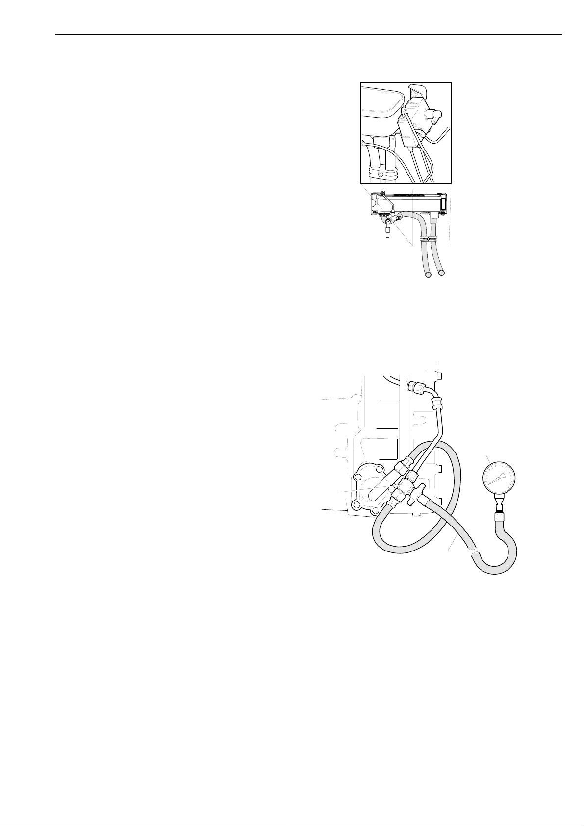
Before chec ki n g
• Fit T adapter 99 404 to the compressed air
line between the valve block V97 or the
proportional valve V76, and the retarder
control piston.
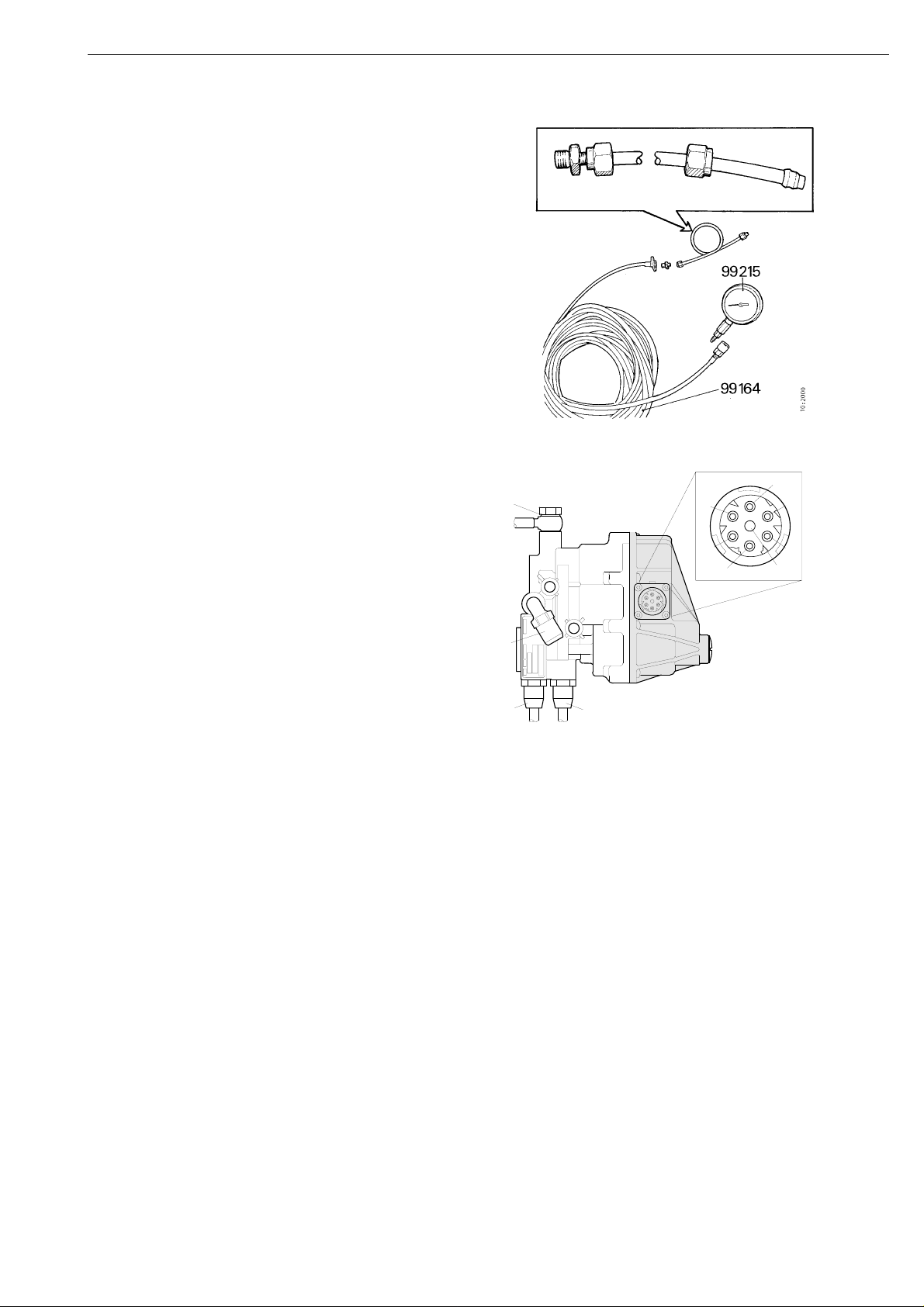
• Connect the hose 99 164 and pressure gauge
99 215.
Note: Make sure the pressure gauge has been
calibrated. Refer to Main Group 10 Brake
system testing for calibrating.
Note: In order to include the hysteresis of the
proportional valve, test readings must be taken
both when the pressure is rising and when it is
falling.
99 404
99 164
99 215
bar
MPa
1
4
11
1050t14b.mkr
©
Scania CV AB 1999, Sweden
7

Troubleshooting
Checking with SD
1
Activate the solenoid valve for feed air and
control of the proportional valve. Then,
check the air pressure in relation to the
current strength.
2
Use the test report, see Test report for test
of proportional valve. Activate the
proportional valve with 200 mA. The
pressure gauge should read 1.6 - 2.0 bar.
3
Increase the activation to 400 mA. The
reading should be 5.4 - 6.0 bar.
4
Increase to maximum current. Decrease to
400 mA. The reading should be 5.4 - 6.0
bar.
5
Decrease further to 200 mA. The reading
should be 1.6 - 2.0 bar.
Checking without SD (requires two
persons)
1
Drive the vehicle at 50 kph and brake with
the retarder lever in position 5, max
position.
2
Correct air pressure is 5.0 bar or higher.
If the value is incorrect
• Check the compensation setting of the
proportional valve in Scania Programmer.
It may be set incorrectly.
©
8
Scania CV AB 1999, Sweden
1050t14b.mkr
If the air pressure stated above is not
obtained
• Make sure that at least 6 bar is reaching the
proportional valve. Use pressure gauge
99 215, hose 99 164, union 1 319 272 and
an 8 mm adapter hose.
• Make the adapter from a 0.5 metre long
piece of 8 mm hose. The adapter hose is to
be fitted with sleeve 814 809, ferrule
813 221 and nut 812 888 on both ends.
These will then fit to union 1 319 272.
• Fit the adapter to hose 99 164 and connect
pressure gauge 99 215. Ta ke a reading at the
distributor piece that supplies the
proportional valve with compressed air.
Troubleshooting
• If there is no pressure, the fault may be in
the solenoid valve for the compressed air
supply, ON/OFF valve.
Note: A minor and controlled air leakage from
the proportional valve vent is normal. A hissing
noise, therefore, does not indicate a fault.
4
A
4
56
7
B
C
D
5
6
7
3
2
3
2
1
115 682
Valve block V97 with integrated proportional
valve. The new valve block requires a higher
pilot frequency, 360 Hz, which is obtained from
control units manufactured from 9902.
1
Pin for proportional valve (+)
2
Pin for proportional valve (-)
3
Pin for solenoid valve for compressed air
supply
If oil appears from the proportional valve vent,
check the sealing rings for the control piston and
the safety valve. Clean also the proportional
valve filter.
1050t14b.mkr
©
Scania CV AB 1999, Sweden
4
Pin for earth
5
Pin for solenoid valve for oil accumulator
6
Pin for earth
A Air connection to oil accumulator
B Air supply
C Air connection to retarder
D Venting
9
114 687
A
B
C
3
83
Troubleshooting
Reasons for improvements introduced
on the old proportional valve.
Impurities entering the valve
Action
The proportional valve on trucks has
occasionally broken due to impurities entering.
A new exchangeable valve with integrated air
filter has been introduced in production from
chassis number SS1238870, SN4391326,
SA9031574 and SLA3503385.
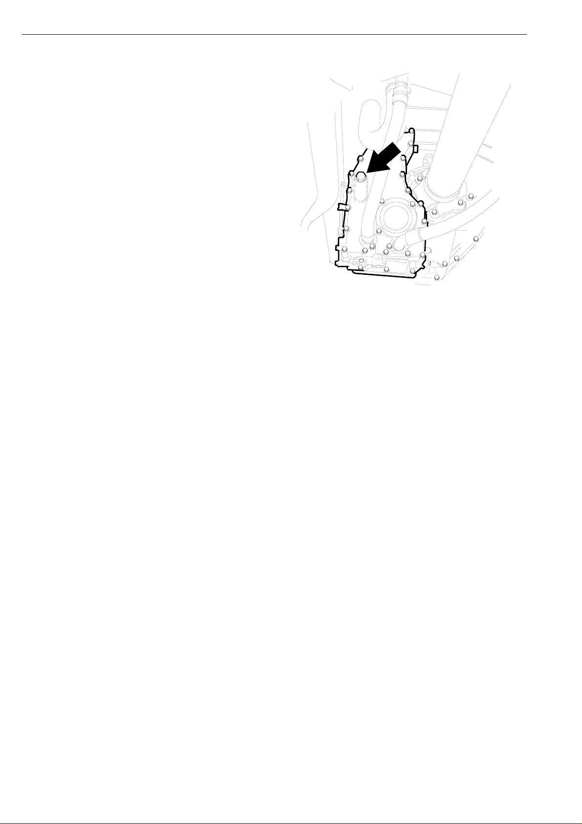
A. Location of proportional valve
Air leakage due to defective check valve
Action
There have been occurrences of air leakage from
the proportional valve vent on trucks and buses.
This is due to a defective rubber check valve.
The fault is easiest to locate in SD. The ON/OFF
valve must be activated. If air leaks through the
vent 4, the check valve is probably defective.
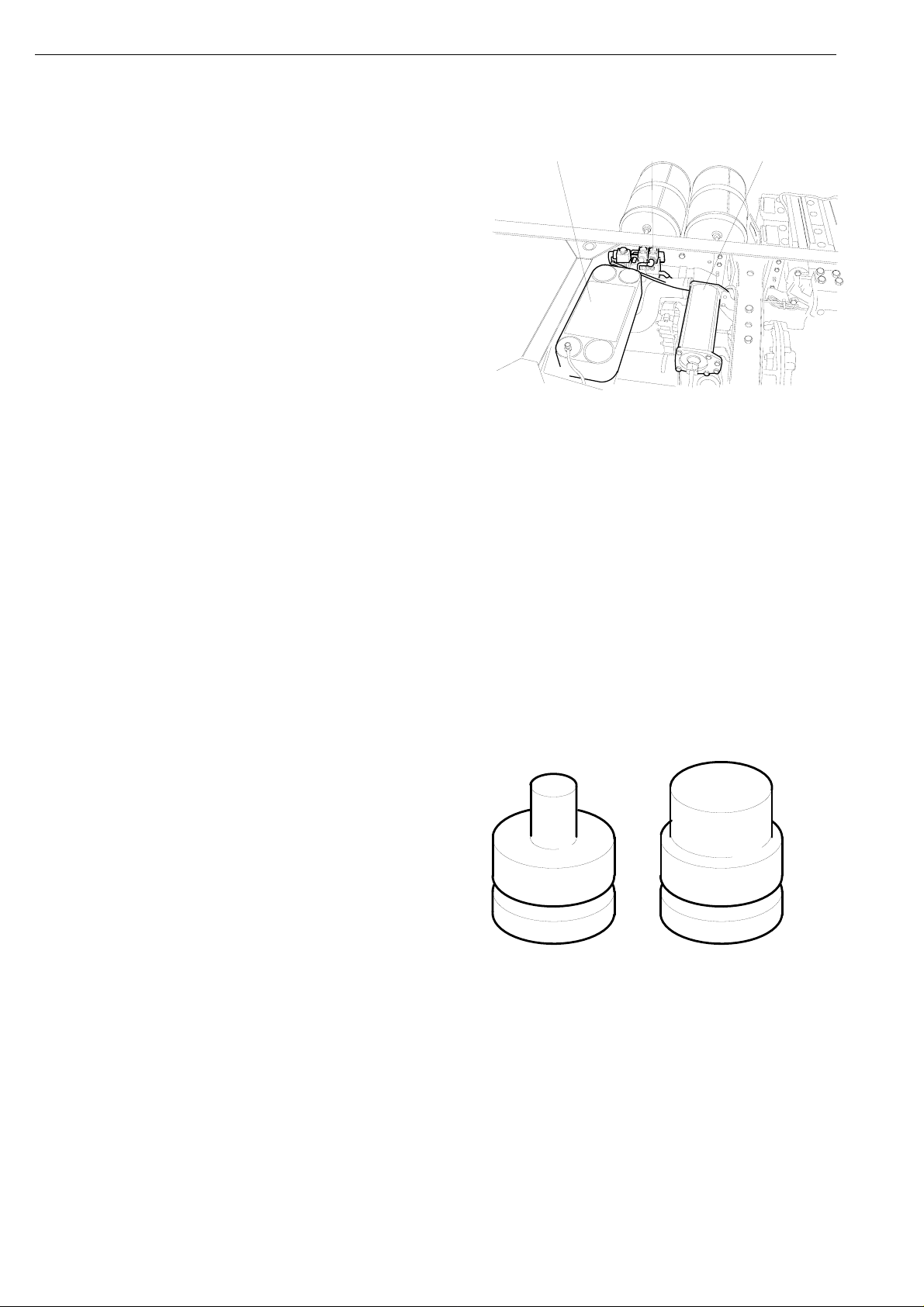
The proportional valve support sleeve has been
modified and was introduced in production from
chassis number SS1246832, SN4405293 and
SA9038846.
AB
A. Old version of support sleeve.
B. New version of support sleeve.
7
11
10
©
Scania CV AB 1999, Sweden
1050t14b.mkr
Loading...