


DI16
03:03 Issue 5.0 en-GB
© Scania CV AB 2016, Sweden
Installation manual
Instrumentation 2.0
Marine engines
DI09, DI13, DI16
344 457
Downloaded from www.Manualslib.com manuals search engine

INSTALLATION
MANUAL
© Scania CV AB 2016, Sweden
03:03 Issue 5.0 en-GB 2
System overview ......................................................................................................3
List of abbreviations............................................................................................ 3
System overview ................................................................................................. 3
Positioning of the displays .................................................................................. 5
Connection ...............................................................................................................7
Electrical cables................................................................................................... 7
Junction box, connection..................................................................................... 8
Junction box, components................................................................................. 11
Main display (DCU), junction blocks ............................................................... 12
Auxiliary display (RP), junction blocks............................................................ 19
Safety module (SDU), connection .................................................................... 22
Gateway – overview.......................................................................................... 22
Position of the monitors on the engine.............................................................. 23
Connecting emergency stop .............................................................................. 25
Engine shutdown override in systems with safety device unit (SDU).............. 26
Using the main display ..........................................................................................27
First start............................................................................................................ 27
Navigation ......................................................................................................... 30
Administration in the main display ................................................................... 33
Configuring and upgrading software with USB memory stick.........................37
Configuring the main display with a USB memory stick ................................. 38
Upgrading the main display or auxiliary display software ............................... 39
Copying one configuration file in the main display.......................................... 39
Configuring the main display via a web browser............................................... 40
Connecting a computer to the main display...................................................... 40
General information about the IP address......................................................... 42
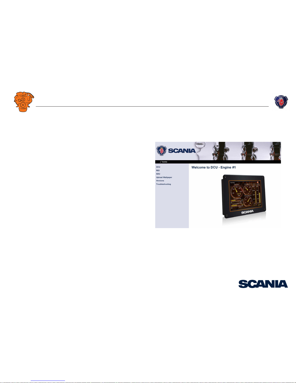
Homepage.......................................................................................................... 43
Logging in to the main display.......................................................................... 44
Important system settings: dcu / Miscellaneous / System Type........................ 44
Password: dcu > Password................................................................................ 45
File management: dcu > File ............................................................................ 46
Configuring input signals: dcu > I/O Configuration > Config Inputs .............. 47
Configure output signals: dcu > I/O Configuration / Config Outputs.............. 63
Designing instrument pages: dcu > Interface Design ....................................... 67
Set the sequences for starting, stopping and for lubrication: dcu > Start/Stop/Pre-
lube ................................................................................................................... 69
Settings for the user interface: dcu > User Interface ........................................ 72
Changing the engine designation: dcu > Engine Model................................... 73
Setting the maintenance interval: dcu > Service Interval ................................. 74
Network settings: dcu > Communication ......................................................... 75
Other functions: dcu > Miscellaneous .............................................................. 77
SDU .................................................................................................................. 82
Auxiliary display ................................................................................................... 83
First start ........................................................................................................... 83
Administration in the auxiliary display ............................................................ 85
Examples of connection of sensors and monitors .............................................. 92
Connection of 4-20 mA, e.g. oil pressure sensor for the reverse gear.............. 92
Connection of PT100, e.g. coolant temperature sensor.................................... 94
Connection of switch input, e.g. low engine oil pressure monitor ................... 96
Downloaded from www.Manualslib.com manuals search engine
INSTALLATION
MANUAL
© Scania CV AB 2016, Sweden
System overview
03:03 Issue 5.0 en-GB 3
System overview
List of abbreviations
The abbreviations in the list below are used in this manual. DCU, RP och SDU ap-
pear in the display interface and in the configuration interface.
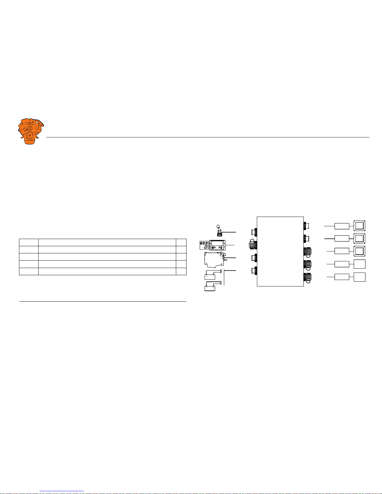
System overview
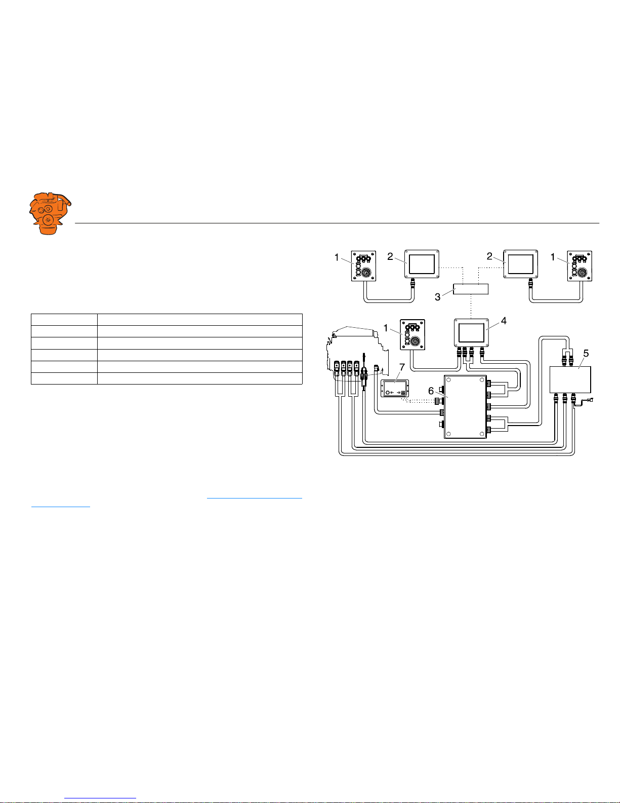
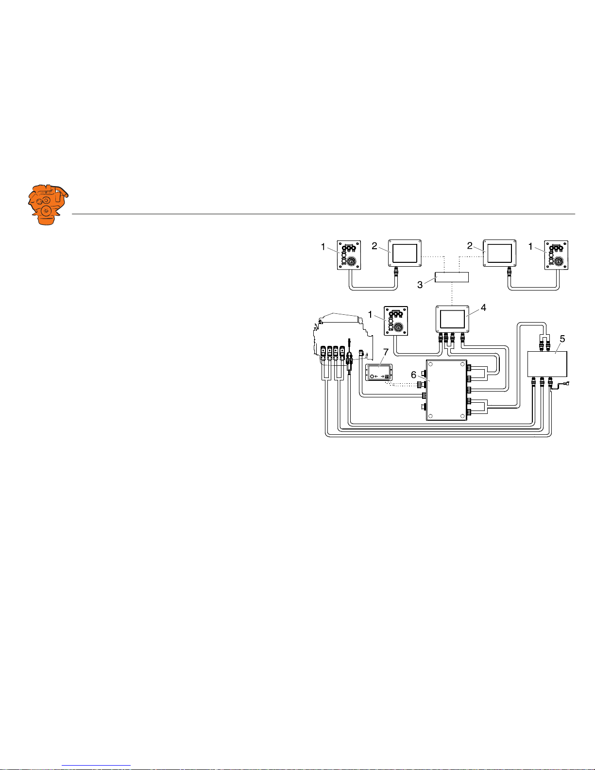
The illustration shows an overview of component parts in a marine engine manage-
ment system prepared for classification.
Main display (DCU)
The main display is the basic unit of the engine management system. Different sensor
values are displayed on the main display touch screen, and different commands are
also carried out there.
The main display is configured using a computer with a web browser via the built in
web server of the main display. This is described in the Configuring the main display
via a web browser section.
Abbreviation Description
DCU Main display
RP Auxiliary display
SDU Safety device unit
FMI Failure Mode Identifier
SPN Suspect Parameter Number
361 900
Example of the layout of a type approved marine engine management system.
1. Control panel.
2. Auxiliary display (RP).
3. Network switch.
4. Main display (DCU).
5. Safety module (SDU).
6. Junction box.
7. Gateway.
Downloaded from www.Manualslib.com manuals search engine
INSTALLATION
MANUAL
© Scania CV AB 2016, Sweden
System overview
03:03 Issue 5.0 en-GB 4
Auxiliary display (RP)
The auxiliary display is an option and has the same user interface as the main display.
The auxiliary display reads the configuration from the main display. This makes it
easy to retrofit.
Control panel
The engine can be started and stopped through the control panel. It can also be used
to activate and adjust engine speed settings 1 or 2. The engine installation can be car-
ried out with or without a control panel.
Network switch
A network switch is only required if more than one auxiliary display is connected to
the engine management system. If the system only contains one auxiliary display, it
is connected directly to the main display via a crossover network cable.
Safety module (SDU)
The safety device unit has monitoring and shutdown functions and is a requirement
for classified engine management systems. It should be easily accessible so that
alarms can be acknowledged in an easy way.
Junction box
The junction box is used to connect all the parts of the engine management system to
the engine. The junction box also contains fuses. It should be easily accessible.
Gateway
The gateway reads specific messages about position and speed via NMEA 2000, so
that the instrumentation can calculate fuel consumption per nautical mile. The gate-
way cannot process messages other than these. The gateway requires software ver-
sion 2.11 or later to be installed in the displays.
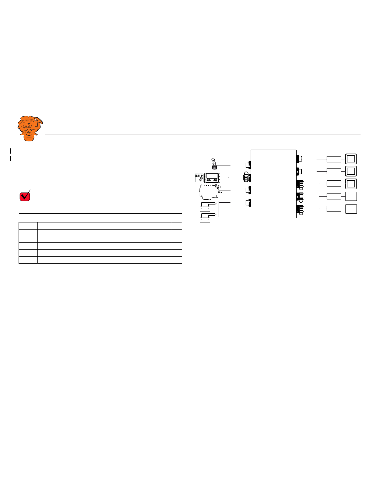
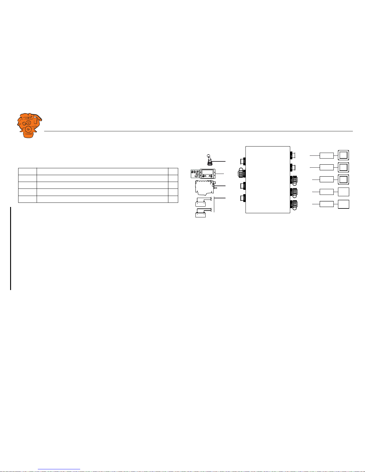
361 900
Example of the layout of a type approved marine engine management system.
1. Control panel.
2. Auxiliary display (RP).
3. Network switch.
4. Main display (DCU).
5. Safety module (SDU).
6. Junction box.
7. Gateway.
Downloaded from www.Manualslib.com manuals search engine
INSTALLATION
MANUAL
© Scania CV AB 2016, Sweden
System overview
03:03 Issue 5.0 en-GB 5
Positioning of the displays
Do not position the displays so that they are exposed to direct sunlight. This impairs
the readability of the displays. The user should have full access to the displays. It
must also be easy to access the connections on the rear of the displays.
IMPORTANT!
The displays must not be fitted on vibrating equipment. They may only be positioned
next to the engine bed if either the engine or the display housing has vibration damp-
ing.
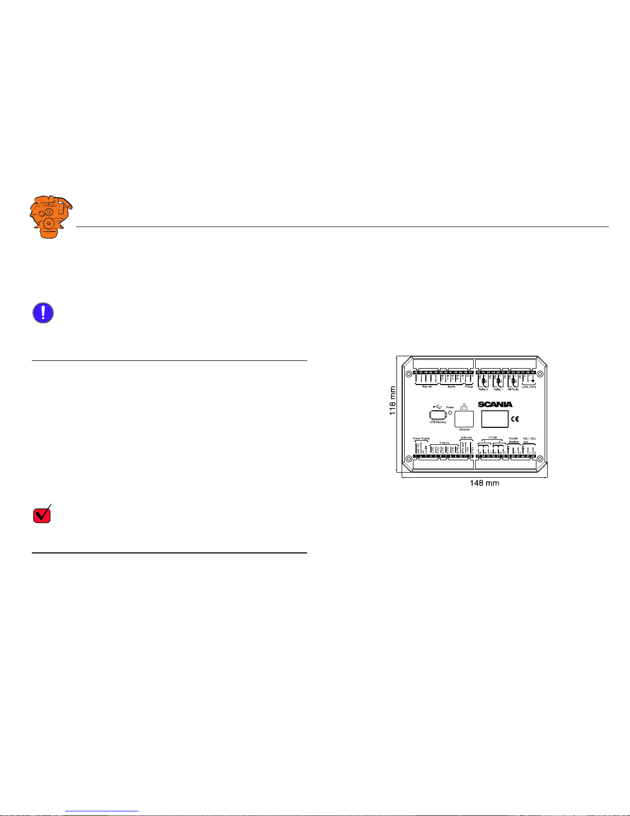
Installation dimensions
Provide a 150 x 120 mm rectangle where the display is to be positioned. There must
be at least 70 mm free space behind the display.
Main display
Scania recommends positioning the main display in the engine compartment for the
following reasons:
• To ensure that operation and monitoring are close to the engine.
• To minimise the lengths of the electrical cables between the sensors and main dis-
play.
• To reduce the risk of electrical interference caused by long electrical cables.
REQUIREMENT!
On a type approved installation, the main display must be located in the engine com-
partment.
361 901
Installation dimensions for the main display and auxiliary display.
Downloaded from www.Manualslib.com manuals search engine

INSTALLATION
MANUAL
© Scania CV AB 2016, Sweden
System overview
03:03 Issue 5.0 en-GB 6
Auxiliary display
The auxiliary display is normally positioned outside the engine compartment, but can
also be positioned in the engine compartment.
Downloaded from www.Manualslib.com manuals search engine

INSTALLATION
MANUAL
© Scania CV AB 2016, Sweden
Connection
03:03 Issue 5.0 en-GB 7
Connection
Electrical cables
To protect against electromagnetic interference, Scania recommends that all electri-
cal cables within the system are twisted in pairs with 35-40 turns/m. This only applies
to external signal cables connected to the system.
IMPORTANT!
If a shielded electrical cable is used, the shielding should be connected to ground, not
to 0 V. Only connect the shielding to one end of the electrical cable.
To provide good separation of the electromagnetic interference that can occur, some
of the electrical cables can be routed separately from the others, e.g. the signal cable
from a magnetic pulse sensor.
Electrical cables for electric power supply must have a minimum cross section of
2.5 mm
2
.
Ground
IMPORTANT!
Separate ground and 0 V. In marine installations, ground and 0 V must not be con-
nected. The hull is ground and the battery negative terminal is 0 V.
24 V and 0 V are filtered in the main display in order to reduce electromagnetic in-
terference. If ground and 0 V are connected together, the filters in the main display
will not function.
Downloaded from www.Manualslib.com manuals search engine
INSTALLATION
MANUAL
© Scania CV AB 2016, Sweden
Connection
03:03 Issue 5.0 en-GB 8
Junction box, connection
Minimum connection
The minimum connection required for the system to function is for the pins on con-
nector C4066 to be connected. If the throttle control is to be controlled via the main
display, then pins 1 and 2 of connector C4068 must also be connected.
Please refer to the electrical system installation manual 03:01 for information on how
to connect the throttle control to the engine control unit. If the throttle control is con-
nected to the engine control unit, secondary throttle control cannot be used.
C4066
Connection of power supply to the engine management system and instrumentation
2.0 (battery).
Note:
If the system has a safety device unit (SDU), 2 separate groups of batteries must be
used.
Pin Description I/O
1 30 voltage, 24 V -
2 Ground (battery negative terminal) -
3 30 voltage, 24 V -
4 Ground (extra battery negative terminal) -
1
2
3
4
DCU
DCU
DCU
SDU
SDU
C4068
C4067
C4052
C4053
C4056
C4058
C4059
C4054
C4055
C4057
C4060
C4061
C4062
C4066
Gat
e
w
a
y
C4001
372 773
Connecting the junction box.
Downloaded from www.Manualslib.com manuals search engine
INSTALLATION
MANUAL
© Scania CV AB 2016, Sweden
Connection
03:03 Issue 5.0 en-GB 9
C4062
Connection to engine connector C4001.
C4067
Diagnostic socket for connecting e.g. SDP3 and CAN communication. Use connec-
tor 1 508 055 and hand crimping tool 99 494.
REQUIREMENT!
Any equipment connected to the connector must comply with the CAN specification.
Pin Description I/O
1 15 voltage: 24 V after fuse F4005 and relay in the junction box. Con-
trolled by the system being active.
-
2Ground -
3CAN high -
4CAN low -
1
2
3
4
DCU
DCU
DCU
SDU
SDU
C4068
C4067
C4052
C4053
C4056
C4058
C4059
C4054
C4055
C4057
C4060
C4061
C4062
C4066
Gat
e
w
a
y
C4001
372 773
Connecting the junction box.
Downloaded from www.Manualslib.com manuals search engine
INSTALLATION
MANUAL
© Scania CV AB 2016, Sweden
Connection
03:03 Issue 5.0 en-GB 10
C4068
Connecting the incoming throttle actuation signal. The update frequency is 100 Hz,
with a median filter on 3 readings.
C4052
Connection to main display via C4054.
C4053
Connection to main display via C4055.
C4056
Connection to main display via C4057.
C4058
Connection to safety device unit (SDU) via C4060.
C4059
Connection to safety device unit (SDU) via C4061.
Pin Description I/O
1 24 V (0.2 A), voltage supply to passive throttle control O
2 Input for signal from throttle control, 4-20 mA I
3 Not used -
4 Not used -
1
2
3
4
DCU
DCU
DCU
SDU
SDU
C4068
C4067
C4052
C4053
C4056
C4058
C4059
C4054
C4055
C4057
C4060
C4061
C4062
C4066
Gat
e
w
a
y
C4001
372 773
Connecting the junction box.
Downloaded from www.Manualslib.com manuals search engine
INSTALLATION
MANUAL
© Scania CV AB 2016, Sweden
Connection
03:03 Issue 5.0 en-GB 11
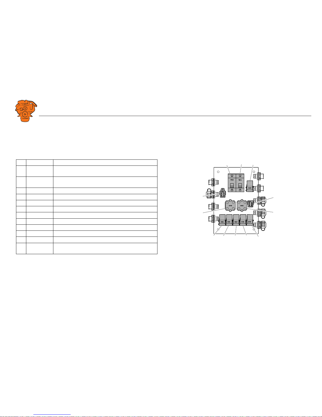
Junction box, components
There are two 20 A miniature circuit breakers in the junction box, one for each bat-
tery connection. Depending on the cable length, it may be necessary to fit extra fuses
for the electrical cable. The junction box also has a number of blade fuses, diodes and
relays as described below.
Designation Description
1 F4010 20 A miniature circuit breaker for incoming voltage from bat-
tery group, main supply
2 F4011 20 A miniature circuit breaker for incoming voltage from bat-
tery group, redundant supply
3 R4005 Relay for 15 voltage
4 F4013 2 x 2 A blade fuses for auxiliary socket
5 D4017 Diode to separate the battery groups, ground
6 D4018 Diode to request shutdown/activation of 15 voltage
7 R4004 Relay for engine shutdown (15 voltage)
8 R4003 Relay for engine shutdown (30 voltage)
9 R4002 Relay for detecting loss of redundant battery group
10 R4001 Relay for detecting loss of main battery group
11 D4016 Diode to separate the battery groups (30 voltage)
12 F4012 2 x 20 A blade fuses for engine control unit, 2 x 5 A blade
fuses for internal supply to panels
347 887
123
4
5
10
9876
12
11
Components in the junction box.
Downloaded from www.Manualslib.com manuals search engine

INSTALLATION
MANUAL
© Scania CV AB 2016, Sweden
Connection
03:03 Issue 5.0 en-GB 12
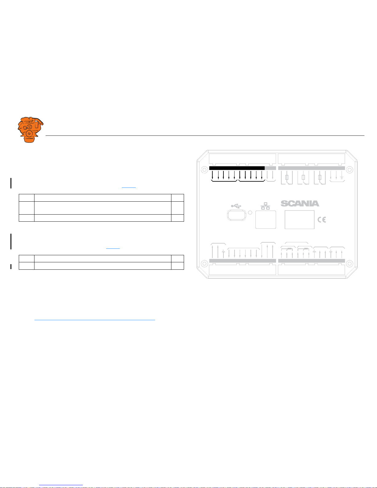
Main display (DCU), junction blocks
The only connection needed for the system to work is for the main display connector
to be connected and the main display to be connected to the junction box via junction
box connectors C4052, C4053 and C4056. See System overview
.
The connections on the main display are listed on the following pages.
Electric power supply: junction block 1-3
The system is designed for a voltage of 24 V.
REQUIREMENT!
Connect the display directly to the battery and not to the starter motor. Use twisted
pair electrical cables and do not make the electrical cable longer than necessary. The
cable cross-sectional area must be at least 2.5 mm².
Alarm at low voltage
There is a 30 second delay before the alarm or warning is activated.
Description I/O
1 24 V main power supply I
2 0 V main power supply I
3 Ground connection I
Warning < 21 V
Alarm < 18 V
0V
Out 1
12 / 24V
Out 3
Out 4
Out 5
Out 6
L
H
L
H
USB Memor
y
Po
w
e
r
Out 2
Pic
kup
H
L
CAN J1939
All Faults
NO
NC
Rela
y 1
NO
NC
Rela
y 2
NO
NC
In 5
A
B
In 1
In 2
In 3
In 4
Inputs
Outputs
1A
1A
1A
P
o
w
er Supply
Ether
net
C
C
C
RIO / SDU
Link
RS-485
Modb
us
24V 0.2A
Ch.
1
Ch.
2
4-20 mA
A
B
C
1
PT100
2
A
B
C
K
e
y set
123456789
10 11 12 13 14 15 16 17 18 19 20 21 22 23 24
36 35 34 33 32 31 30 29 28 2 7 26 2548 47 46 45 44 43 42 41 40 39 38 37
347 812
Junction blocks on the main display.
Downloaded from www.Manualslib.com manuals search engine
INSTALLATION
MANUAL
© Scania CV AB 2016, Sweden
Connection
03:03 Issue 5.0 en-GB 13
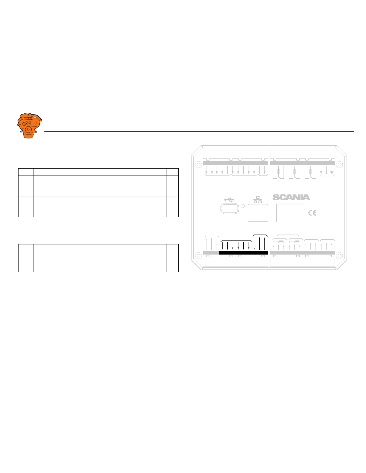
Change-over output: junction block 4-9
The main display has six 24 V outputs that can be configured individually for option-
al functions or events. See the 12/24V Output Functions
section.
4-20 mA input: junction block 10-12
The main display has two configurable analogue inputs. Information on how to con-
figure the inputs is in the 4-20 mA
section.
If the signal is outside the following limit values, a warning is displayed on the dis-
play.
• Less than 2 mA: defective
• Over 24 mA: short circuit
2-4 mA is treated as 4 mA and 20-22 mA is treated as 20 mA. The updating frequen-
cy is 2 Hz.
Description I/O
4 24 V output #1 (0.5 A shared with output #2) O
5 24 V output #2 (0.5 A shared with output #1) O
6 24 V output #3 (0.2 A) O
7 24 V output #4 (0.2 A) O
8 24 V output #5 (0.2 A) O
9 24 V output #6 (0.2 A) O
Description I/O
10 24 V supply (0.2 A). The junction block is occupied O
11 4-20 mA input #1 I
12 4-20 mA input #2 I
0V
12 / 24V
L
H
L
H
USB Memor
y
Po
w
e
r
Pic
kup
H
L
CAN J1939
All Faults
NO
NC
Rela
y 1
NO
NC
Rela
y 2
NO
NC
In 5
A
B
In 1
In 2
In 3
In 4
Inputs
1A
1A
1A
P
o
w
er Supply
Ether
net
C
C
C
RIO / SDU
Link
RS-485
Modb
us
Out 1
Out 3
Out 4
Out 5
Out 6
Out 2
Outputs
24V 0.2A
Ch.
1
Ch.
2
4-20 mA
A
B
C
1
PT100
2
A
B
C
K
e
y set
123456789
10 11 12 13 14 15 16 17 18 19 20 21 22 23 24
36 35 34 33 32 31 30 29 28 27 26 2548 47 46 45 44 43 42 41 40 39 38 37
347 813
Junction blocks on the main display.
Downloaded from www.Manualslib.com manuals search engine
INSTALLATION
MANUAL
© Scania CV AB 2016, Sweden
Connection
03:03 Issue 5.0 en-GB 14
PT100 input: junction block 13-18
There are two PT100 inputs in the main display. The inputs are adapted for PT100
sensors with 2 or 3 electrical cables. Connect the electrical cables as follows:
2 wire PT100: Bridge A and B. Connect one wire to AB and the other to C.
3 wire PT100: Connect A to A, B to B and C to C.
4 wire PT100: Connect in the same way as 3 wire PT100, but note that the fourth
wire, D, should not be connected. It should hang loose or, if necessary, be cut off.
Information on how to configure the inputs is in the PT100
section.
If the signal is outside the following limit values, a warning is displayed on the dis-
play.
The updating frequency is 2 Hz.
Description I/O
13 PT100 #1 A I
14 PT100 #1 B I
15 PT100 #1 C I
16 PT100 #2 A I
17 PT100 #2 B I
18 PT100 #2 C I
Below 90
ohms
short circuit
Above 390
ohms
defective
0V
12 / 24V
L
H
L
H
USB Memor
y
Po
w
e
r
Pic
kup
H
L
CAN J1939
All Faults
NO
NC
Rela
y 1
NO
NC
Rela
y 2
NO
NC
In 5
A
B
In 1
In 2
In 3
In 4
Inputs
1A
1A
1A
P
o
w
er Supply
Ether
net
C
C
C
RIO / SDU
Link
RS-485
Modb
us
Out 1
Out 3
Out 4
Out 5
Out 6
Out 2
Outputs
24V 0.2A
Ch.
1
Ch.
2
4-20 mA
A
B
C
1
PT100
2
A
B
C
K
e
y set
123456789
10 11 12 13 14 15 16 17 18 19 20 21 22 23 24
36 35 34 33 32 31 30 29 28 27 26 2548 47 46 45 44 43 42 41 40 39 38 37
369 835
Junction blocks on the main display.
Downloaded from www.Manualslib.com manuals search engine
INSTALLATION
MANUAL
© Scania CV AB 2016, Sweden
Connection
03:03 Issue 5.0 en-GB 15
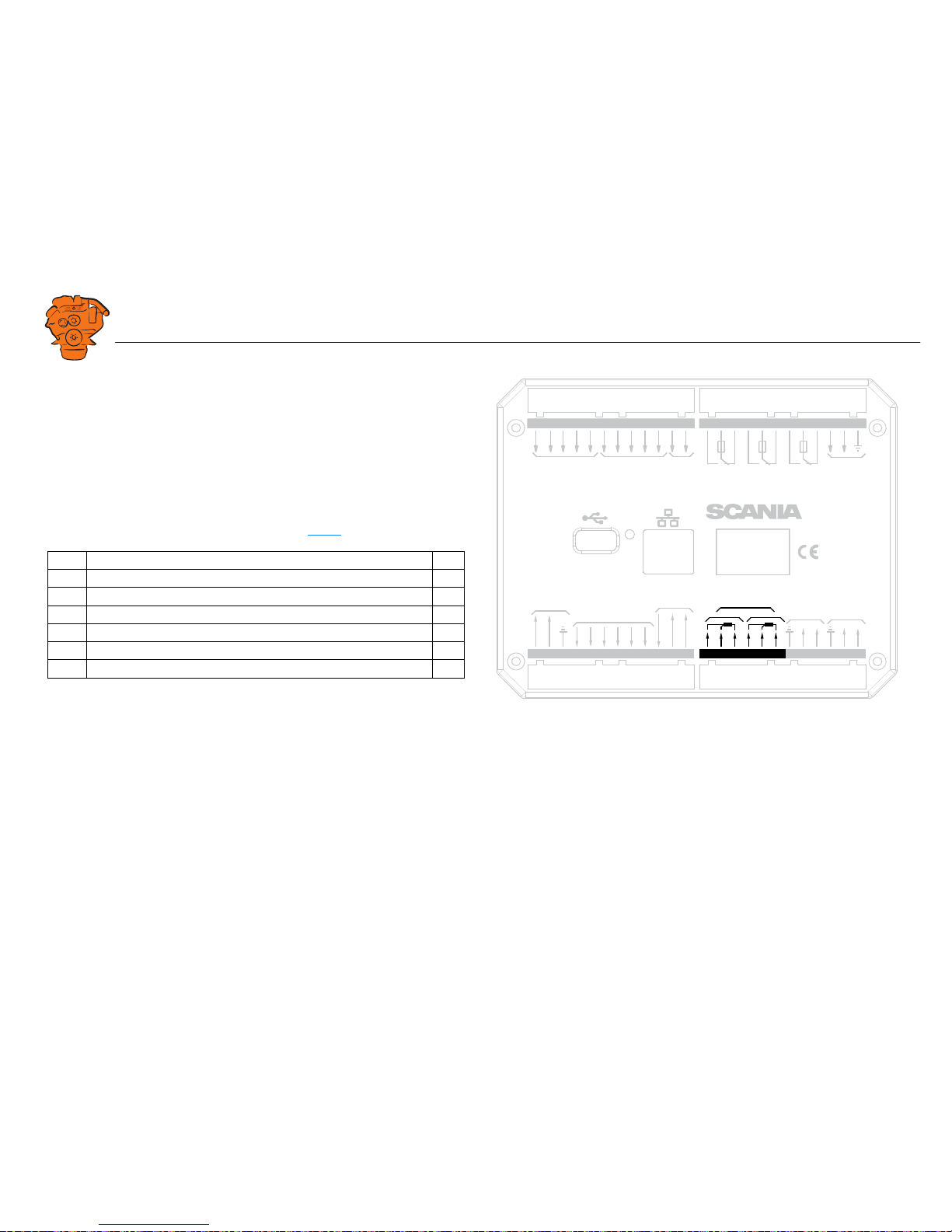
Modbus RTU, RS-485: junction block 19-21
The main display has a built-in Modbus
TM
interface, on both RS-485 and Ethernet.
The latter can also be designated Modbus TCP.
RIO link: junction block 22-24
Not used.
J1939 CAN interface: junction block 25-27
Connection to engine control unit via CAN. The connection is terminated.
Description I/O
19 Shielded I
20 Low I
21 High I
Description I/O
25 Not used I
26 Low I
27 High I
0V
12 / 24V
L
H
L
H
USB Memor
y
Po
w
e
r
Pic
kup
H
L
CAN J1939
All Faults
NO
NC
Rela
y 1
NO
NC
Rela
y 2
NO
NC
In 5
A
B
In 1
In 2
In 3
In 4
Inputs
1A
1A
1A
P
o
w
er Supply
Ether
net
C
C
C
RIO / SDU
Link
RS-485
Modb
us
Out 1
Out 3
Out 4
Out 5
Out 6
Out 2
Outputs
24V 0.2A
Ch.
1
Ch.
2
4-20 mA
A
B
C
1
PT100
2
A
B
C
K
e
y set
123456789
10 11 12 13 14 15 16 17 18 19 20 21 22 23 24
36 35 34 33 32 31 30 29 28 27 26 2548 47 46 45 44 43 42 41 40 39 38 37
369 836
Junction blocks on the main display.
Downloaded from www.Manualslib.com manuals search engine
INSTALLATION
MANUAL
© Scania CV AB 2016, Sweden
Connection
03:03 Issue 5.0 en-GB 16
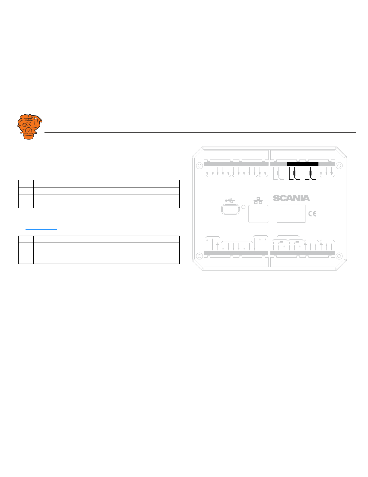
Relay for all faults: junction block 28-30
The relay is activated when there are no active faults and is deactivated when a fault
occurs. Every new event is counted as a fault in the alarm list, except diagnostics
messages with a white ranking. The relay can be used to switch on an external lamp
or emit an acoustic signal, for example.
Relay #1: junction block 31-33
The relay can be configured so that it is activated for any of the built in functions. See
the Relay Functions
section.
Description I/O
28 NC (1 A) -
29 C (1 A) -
30 NO (1 A) -
Description I/O
31 NC (1 A) -
32 C (1 A) -
33 NO (1 A) -
0V
12 / 24V
L
H
L
H
USB Memor
y
Po
w
e
r
Pic
kup
H
L
CAN J1939
All Faults
NO
NC
Rela
y 1
NO
NC
Rela
y 2
NO
NC
In 5
A
B
In 1
In 2
In 3
In 4
Inputs
1A
1A
1A
P
o
w
er Supply
Ether
net
C
C
C
RIO / SDU
Link
RS-485
Modb
us
Out 1
Out 3
Out 4
Out 5
Out 6
Out 2
Outputs
24V 0.2A
Ch.
1
Ch.
2
4-20 mA
A
B
C
1
PT100
2
A
B
C
K
e
y set
123456789
10 11 12 13 14 15 16 17 18 19 20 21 22 23 24
36 35 34 33 32 31 30 29 28 27 26 2548 47 46 45 44 43 42 41 40 39 38 37
369 838
Junction blocks on the main display.
Downloaded from www.Manualslib.com manuals search engine

INSTALLATION
MANUAL
© Scania CV AB 2016, Sweden
Connection
03:03 Issue 5.0 en-GB 17
Relay #2: junction block 34-36
The relay can be configured so that it is activated for any of the built in functions. See
the Relay Functions
section.
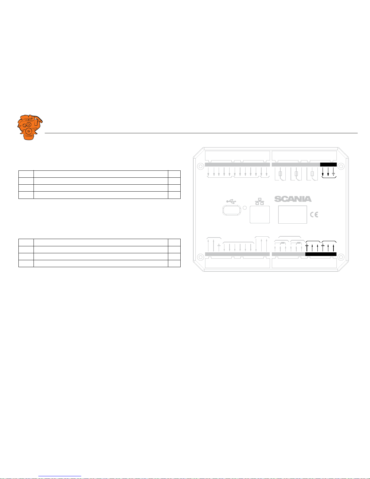
Input for magnetic pulse sensor: junction block 37-38
An auxiliary rotational speed sensor is connected here. Only shield the electrical ca-
ble on the sensor side. Information on configuration is in the Local Pickup
section.
Description I/O
34 NC (1 A) -
35 C (1 A) -
36 NO (1 A) -
Description I/O
37 A I
38 B I
0V
12 / 24V
L
H
USB Memor
y
Po
w
e
r
In 5
In 1
In 2
In 3
In 4
Inputs
P
o
w
er Supply
Ether
net
Pic
kup
Rela
y 2
NO
NC
A
B
1A
C
H
L
CAN J1939
All Faults
NO
NC
Rela
y 1
NO
NC
1A
1A
C
C
RIO / SDU
Link
Out 1
Out 3
Out 4
Out 5
Out 6
Out 2
Outputs
24V 0.2A
Ch.
1
Ch.
2
4-20 mA
L
H
RS-485
Modb
us
A
B
C
1
PT100
2
A
B
C
K
e
y set
123456789
10 11 12 13 14 15 16 17 18 19 20 21 22 23 24
36 35 34 33 32 31 30 29 28 27 26 2548 47 46 45 44 43 42 41 40 39 38 37
347 816
Junction blocks on the main display.
Downloaded from www.Manualslib.com manuals search engine
INSTALLATION
MANUAL
© Scania CV AB 2016, Sweden
Connection
03:03 Issue 5.0 en-GB 18
Change-over input: junction block 39-43
There are five 24 V inputs that can be configured individually for available functions.
For example, a low oil pressure sensor can be connected, or the input can be config-
ured to activate a built in function such as automatic start.
If there is a safety device unit (SDU) in the system, three of the inputs are reserved.
Information on how to configure the inputs is in the Switch
section.
Connection of control panel. junction block 44-48
If there is no control panel in the system, inputs 44-48 can also be configured. How-
ever, this only applies if the software version of the display is 2.12 or later. Informa-
tion on how to configure the inputs is in the Switch
section.
Ethernet (Modbus TCP)
The main display is connected to the LAN or directly to a computer via a standard
CAT-5 network. Connect to port RJ45 via a crossover network cable. The IP address
in the main display or the computer may need to be changed in order to configure the
main display via a web browser.
USB input
See the Configuring and upgrading software with USB memory stick section.
Description I/O
39-41 24 V inputs. The inputs are reserved if there is a safety device unit in
the system.
I
42-43 24 V inputs, configurable. I
Description I/O
44-48 24 V inputs. Reserved in systems with control panel. I
0V
12 / 24V
L
H
USB Memor
y
Po
w
e
r
Inputs
P
o
w
er Supply
Ether
net
Pic
kup
Rela
y 2
NO
NC
A
B
1A
C
H
L
CAN J1939
All Fau lts
NO
NC
Rela
y 1
NO
NC
1A
1A
C
C
RIO / SDU
Link
Out 1
Out 3
Out 4
Out 5
Out 6
Out 2
Outputs
24V 0.2A
Ch.
1
Ch.
2
4-20 mA
L
H
RS-485
Modb
us
A
B
C
1
PT100
2
A
B
C
In 5
In 1
In 2
In 3
In 4
K
e
y set
123456789
10 11 12 13 14 15 16 17 18 19 20 21 22 23 24
36 35 34 33 32 31 30 29 28 27 26 2548 47 46 45 44 43 42 41 40 39 38 37
347 817
Junction blocks on the main display.
Downloaded from www.Manualslib.com manuals search engine
INSTALLATION
MANUAL
© Scania CV AB 2016, Sweden
Connection
03:03 Issue 5.0 en-GB 19
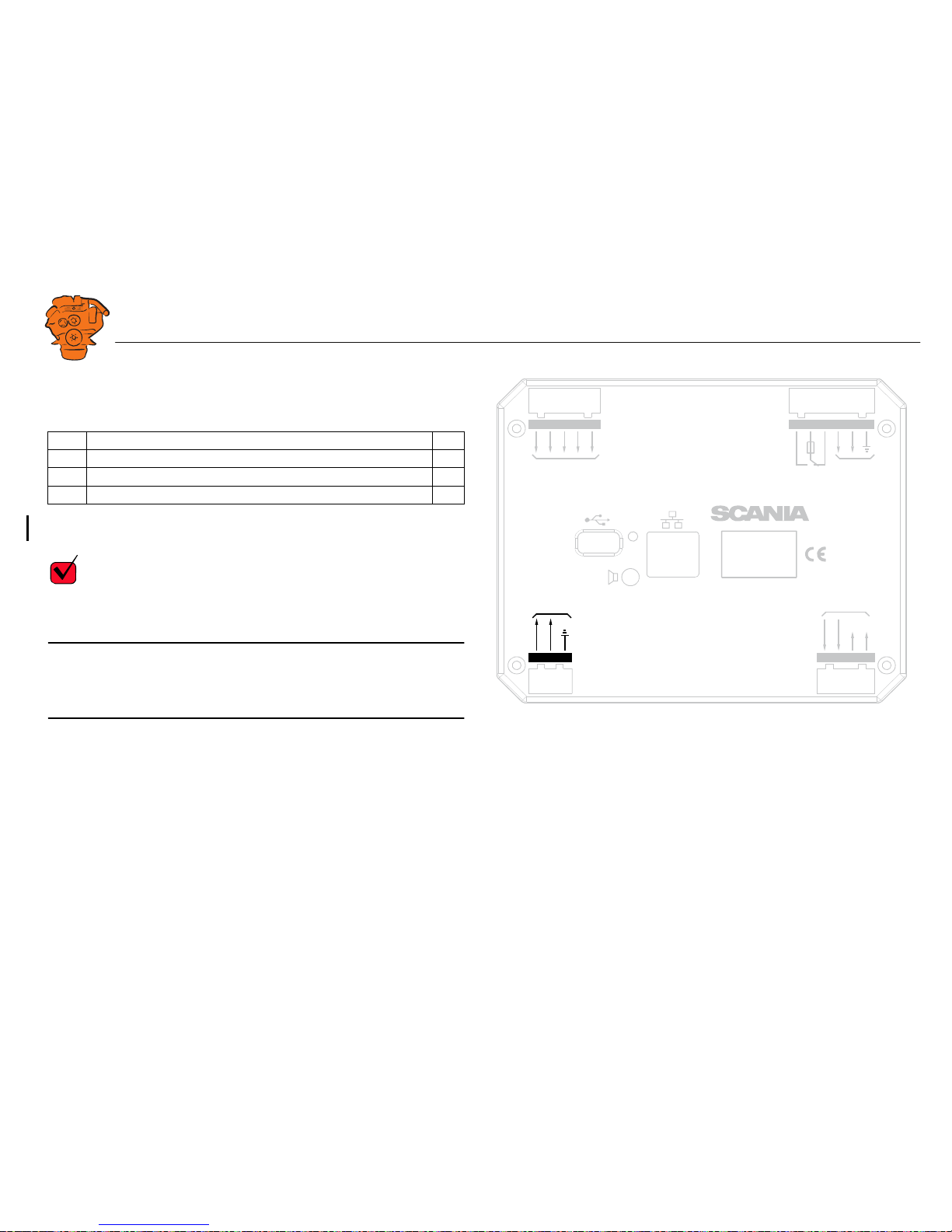
Auxiliary display (RP), junction blocks
Electric power supply: junction block 1-3
The auxiliary display must have a separate electric power supply. The system is de-
signed for a voltage of 24 V.
REQUIREMENT!
Connect the display directly to the battery and not to the starter motor. Use twisted
pair electrical cables and do not make the electrical cables longer than necessary. The
cable cross-sectional area must be at least 2.5 mm².
Note:
Scania recommends connecting the auxiliary display to the same fuse group as the
main display.
Alarm at low voltage
There is a 30 second delay before an alarm or warning is activated.
Description I/O
1 24 V main power supply I
2 0 V main power supply I
3 Ground connection I
Warning < 21 V
Alarm < 18 V
0V
12 / 24V
123
21 22 23 24
L
H
USB Memor
y
Po
w
e
r
P
o
w
er Supply
Ether
net
30 29 28 27 26 25
H
L
CAN J1939
All Faults
NO
NC
1A
C
RIO / SDU Link
0V
12 / 24V
A
udio
Line Out
48 47 46 45 44
K
e
y set
347 825
Junction blocks on the auxiliary display.
Downloaded from www.Manualslib.com manuals search engine
INSTALLATION
MANUAL
© Scania CV AB 2016, Sweden
Connection
03:03 Issue 5.0 en-GB 20
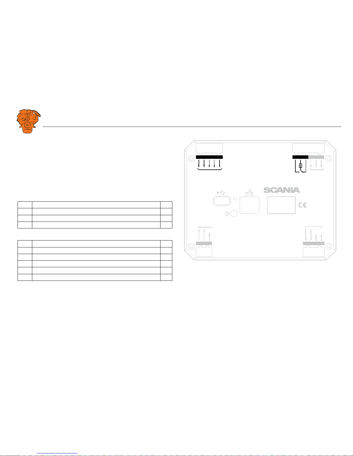
RIO link: junction block 21-24
Not used.
J1939 CAN interface: junction block 25-27
Not used. The connection is terminated.
Relay for all faults: junction block 28-30
The relay is activated when there are no active faults and is deactivated when a fault
occurs. Every new event is counted as a fault in the alarm list, except diagnostics
messages with a white ranking.
Connection of control panel. junction block 44-48
Description I/O
28 NC -
29 C -
30 NO -
Description I/O
44 24 V input #6. Reserved for the control panel I
45 24 V input #7. Reserved for the control panel I
46 24 V input #8. Reserved for the control panel I
47 24 V input #9. Reserved for the control panel I
48 24 V input #10. Reserved for the control panel I
0V
12 / 24V
123
21 22 23 24
L
H
USB Memor
y
Po
w
e
r
P
o
w
er Supply
Ether
net
30 29 28 27 26 25
H
L
CAN J1939
All Faults
NO
NC
1A
C
RIO / SDU Link
0V
12 / 24V
A
udio
Line Out
48 47 46 45 44
K
e
y set
347 823
Junction blocks on the auxiliary display.
Downloaded from www.Manualslib.com manuals search engine
INSTALLATION
MANUAL
© Scania CV AB 2016, Sweden
Connection
03:03 Issue 5.0 en-GB 21
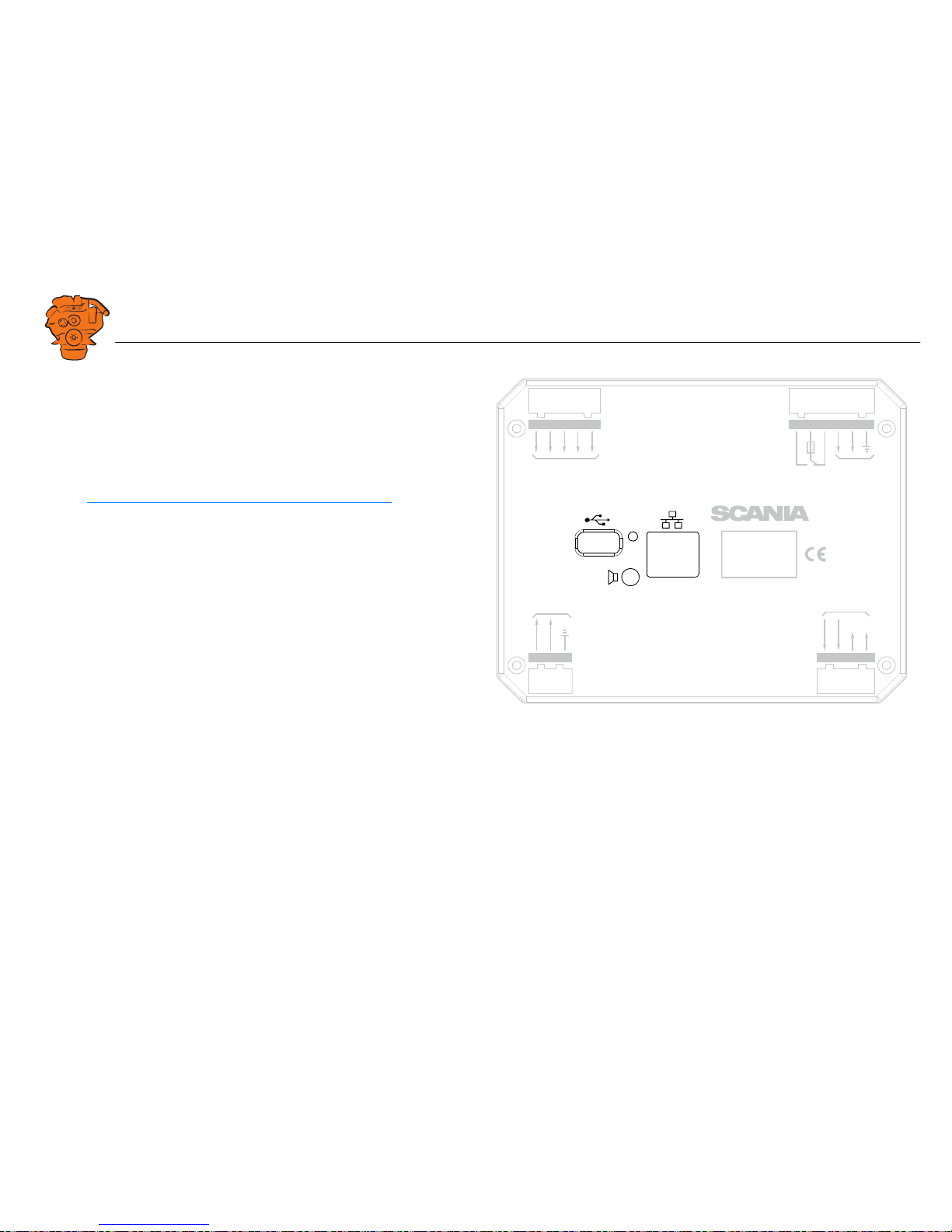
Ethernet (Modbus TCP)
Connection to the LAN.
USB input
See the Configuring and upgrading software with USB memory stick section.
Loudspeaker output
The auxiliary display has a standard output of 3.5 mm for the connection of regular
computer speakers. The installation will then have more sounds than just the built in
buzzer, and different types of sound can be linked with different events. This is how
to activate external speakers:
• In the auxiliary display, go to Menu > Settings > Sound.
• Activate the Speakers option with the Sound Configuration button.
0V
12 / 24V
123
21 22 23 24
L
H
USB Memor
y
Po
w
e
r
P
o
w
er Supply
Ether
net
30 29 28 27 26 25
H
L
CAN J1939
All Faults
NO
NC
1A
C
RIO / SDU Link
0V
12 / 24V
A
udio
Line Out
48 47 46 45 44
K
e
y set
347 824
Junction blocks on the auxiliary display.
Downloaded from www.Manualslib.com manuals search engine
INSTALLATION
MANUAL
© Scania CV AB 2016, Sweden
Connection
03:03 Issue 5.0 en-GB 22
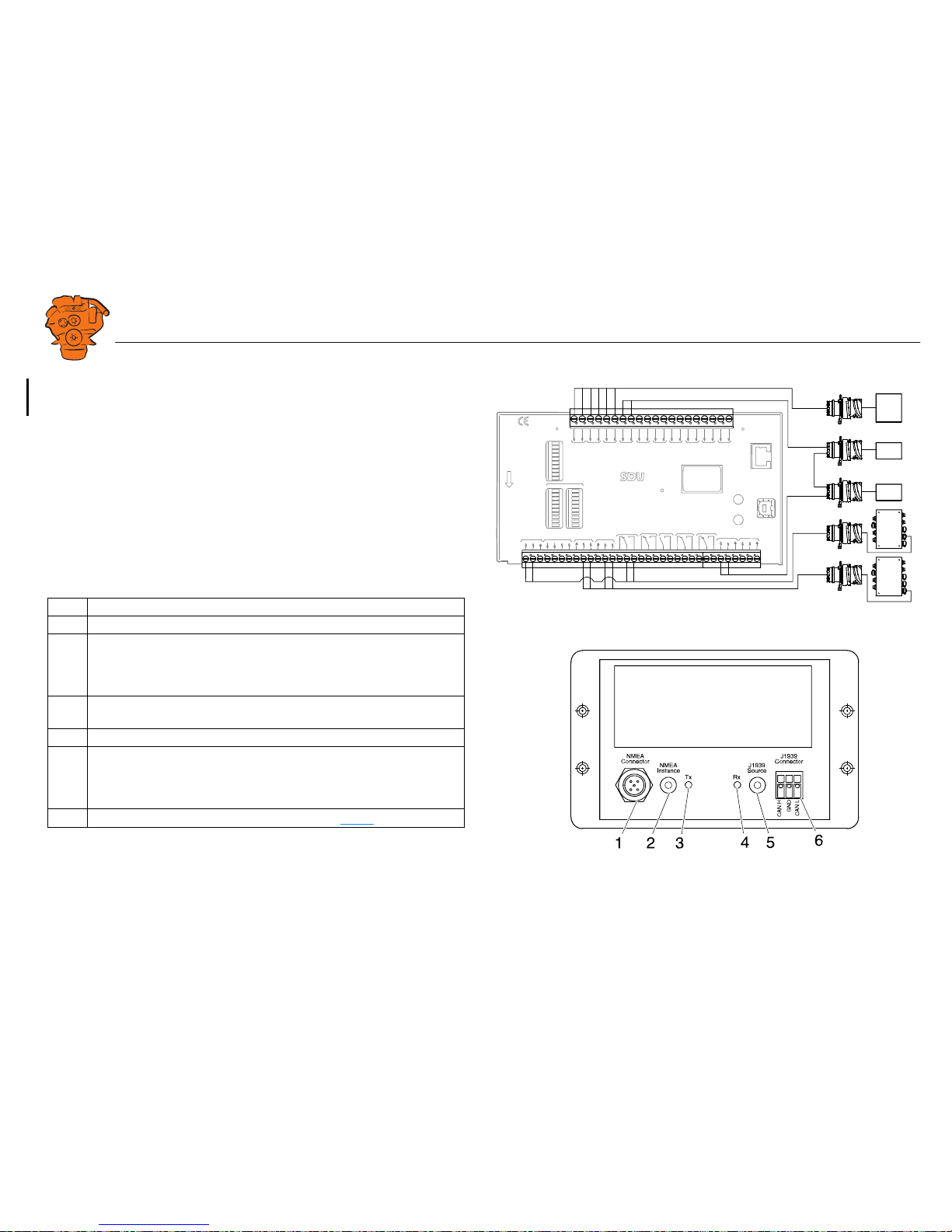
Safety module (SDU), connection
The illustration shows the safety device unit connections.
Gateway – overview
Pos. Description
1 Connection to the ship NMEA 2000 network.
2 "NMEA Instance" rotary control. Set the instance which the gateway trans-
mits to other units. Used if 2 or more gateways are connected to the same
NMEA 2000 network. In such a case, make sure that each gateway has a
unique instance, e.g. "0" and "1".
3 Blue "Tx" LED, indicates that data is being received from NMEA 2000
every 2.5 seconds.
4 Green "Rx" LED, indicates that data is being sent to J1939.
5 "J1939 Source" rotary control. Set the instance for the NMEA 2000 GPS
which the information should be loaded from. If the gateway does not re-
ceive any signals from a GPS with the selected instance within 30 seconds,
all valid GPS data is transferred automatically.
6 Connection to connector C4067 junction box. See C4067
.
SWITCH 1
SWITCH 2
SWITCH 3
SWITCH 4
SWITCH 5
SWITCH 6
SWITCH 7
SWITCH 8
SWITCH 1
SWITCH 2
SWITCH 3
SWITCH 4
SWITCH 5
SWITCH 6
SWITCH 7
SWITCH 8
SHUTD
O
WN
F
A
UL
T
SWITCH 1 SWITCH 2 SWITCH 3 SWITCH 4 SWITCH 5 SWITCH 6 SWITCH 7 SWITCH 8
S
T
A
TUS
PO
WER
CRANK CU
T
OFF
R
UNNING
T
A
CHO 1
T
A
CHO 2
SHUTD
O
WN
O
VERRIDE
B
UZZER
COM 1
COM 2
COM 3
SHUTD
O
WN
O
VERRIDE
A
CKN
O
WLEDGE
COM 3
CONFIGUR
A
TION
ETHERNET
shutd
o
wn unit
RELEASE
SHUTD
O
WN
O
VERSPEED
SHUTD
O
WN COIL
SHUTD
O
WN
O
VERIDE
SHUTD
O
WN
CRANK
CU
T
OFF
B
UZZLER
F
A
ULT R
UNNING
COM 1
DCU LINK
COM 2
RS 485
MOD
B
US
R
TU
A
CKN
O
WLEDGE
O
VERSPEED
TEST
COM 4
USB
T
A
CHO 2
T
A
CHO 1
S
H
U
T
D
O
W
N
C
O
I
L
S
U
P
P
L
Y
1 24V
4 24V
6 24V
20V
70V
50V
3
8
34
35
36
37
38
39
40
41
42
43
421
422
423
424
425
426
50
51
52
53
9
10
11
12
13
14
15
16
17
18
19
20
21
22
23
24
25
26
27
28
29
30
31
32
33
H
L
H
L
C4063
T4003
T4004
C4064
T4006
T4007
T4006
T4007
C4058
C4059
C4074
C4060
C4061
C4065
372 772
361 902
Downloaded from www.Manualslib.com manuals search engine
INSTALLATION
MANUAL
© Scania CV AB 2016, Sweden
Connection
03:03 Issue 5.0 en-GB 23
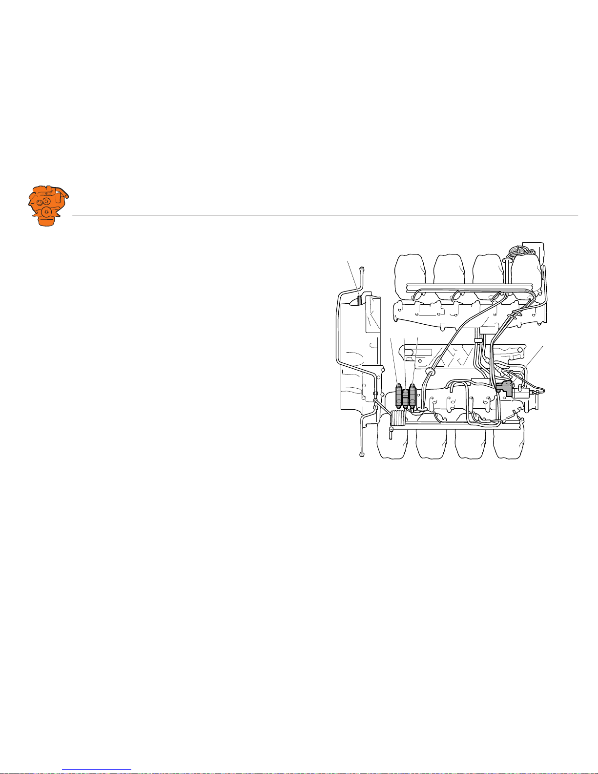
Position of the monitors on the engine
The illustration shows the position of the monitors on DI09 and DI13.
See 02:01 Engine for information on where to connect external monitoring sensors.
1
5
2
4
3
347 830
DI09, DI13.
1. Coolant pressure monitor, T4006.
2. Oil pressure monitor, T4003.
3. Coolant temperature monitor, T4004.
4. Fuel pressure monitor, T4007.
5. Engine speed monitor, T4005.
Downloaded from www.Manualslib.com manuals search engine
INSTALLATION
MANUAL
© Scania CV AB 2016, Sweden
Connection
03:03 Issue 5.0 en-GB 24
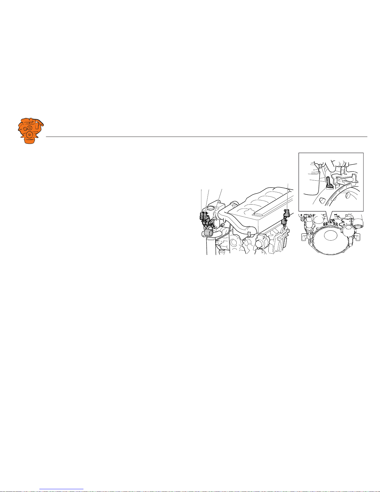
The illustration shows the location of the monitors on DI16.
See 02:01 Engine for information on where to connect external monitoring sensors.
5
2
43
1
347 831
DI16.
1. Engine speed monitor, T4005.
2. Oil pressure monitor, T4003.
3. Coolant temperature monitor, T4004.
4. Coolant pressure monitor, T4006.
5. Fuel pressure monitor, T4007.
Downloaded from www.Manualslib.com manuals search engine
INSTALLATION
MANUAL
© Scania CV AB 2016, Sweden
Connection
03:03 Issue 5.0 en-GB 25
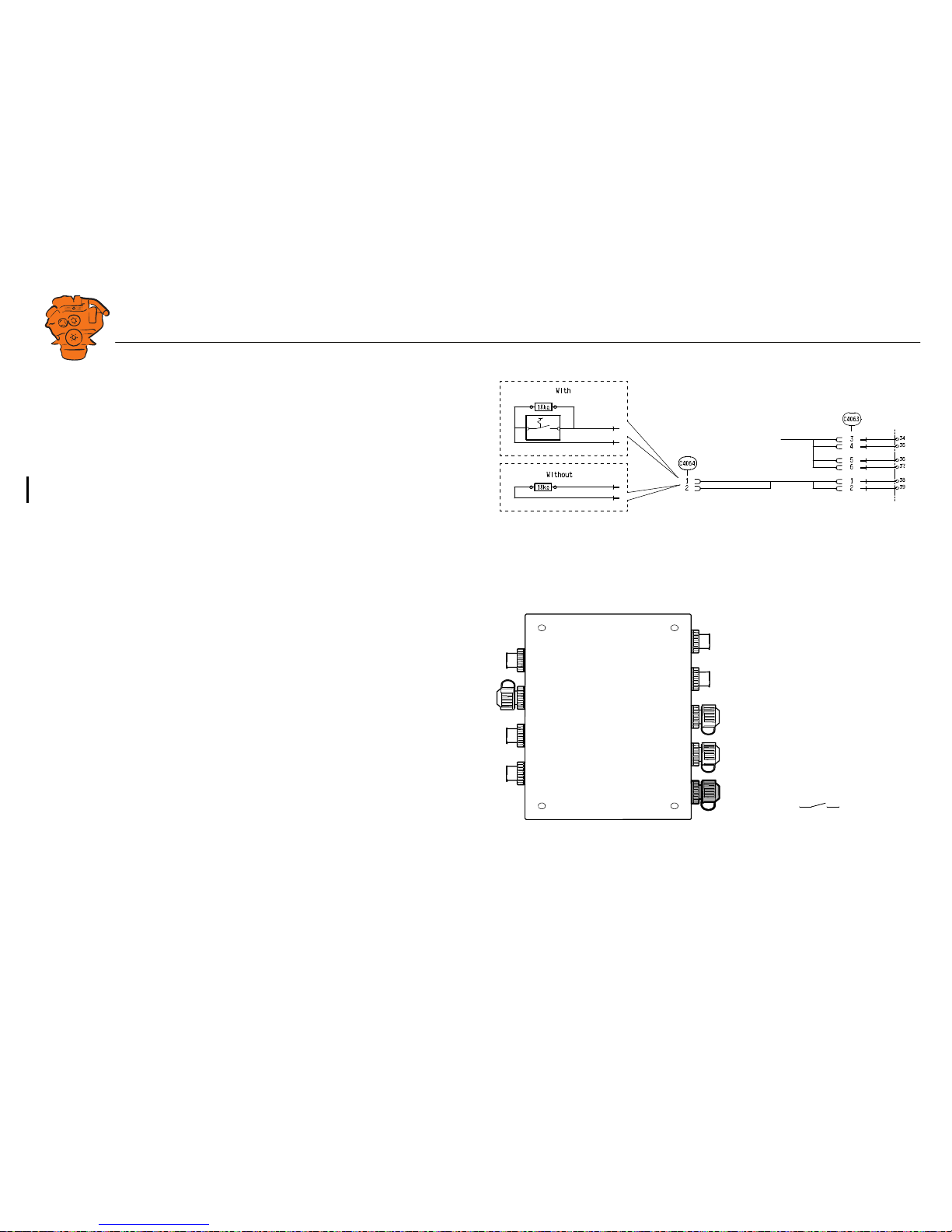
Connecting emergency stop
It is possible to connect an emergency stop which disconnects the voltage to the en-
gine control unit. The connection is made in different ways, depending on whether
the system has a safety device unit (SDU) or not.
System with safety device unit (SDU)
Connect a switch with a 10 kohms resistor to connector C4064 in cable harness con-
nected to the safety device unit.
System without safety device unit (SDU)
Connect a regular open switch to pin 3 in connector C4059 in the junction box. The
switch should be connected to 24 V.
Use connector 2 131 199 and the following tools:
• Hand crimping tool 99 494
• Hand crimping tool 99 491
347 885
SDU
System with safety device unit: connection of emergency stop to C4064.
+24V
C4059-3
347 886
System without safety device unit: connecting an emergency stop to the junction box.
Downloaded from www.Manualslib.com manuals search engine
INSTALLATION
MANUAL
© Scania CV AB 2016, Sweden
Connection
03:03 Issue 5.0 en-GB 26
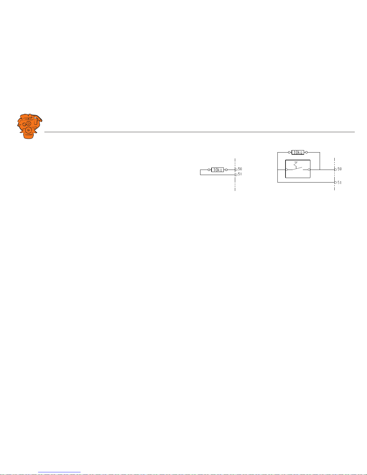
Engine shutdown override in systems with safety
device unit (SDU)
It is possible to override engine shutdown requested by the safety device unit in sys-
tems prepared for classification. Proceed as follows:
1. Remove the existing 10 kohms resistor between junction blocks 50 and 51 in the
safety device unit.
2. Connect a switch with a 10 kohms resistor between junction blocks 50 and 51.
SDU
347 888
SDU
12
Overriding engine shutdown requested by the safety device unit.
Downloaded from www.Manualslib.com manuals search engine

INSTALLATION
MANUAL
© Scania CV AB 2016, Sweden
Using the main display
03:03 Issue 5.0 en-GB 27
Using the main display
First start
When you start the main display for the first time or have performed a factory reset,
a power-on wizard is displayed. All settings made in the wizard can also be made at
a later stage. The first power-on wizard contains the following steps:
1. Calibrate Touch
Calibrate the display by pressing the 5 marks which are displayed one after another.
The calibration must be performed correctly in order to continue with the wizard.
372 511
Main display first power on wizard.
372 512
Downloaded from www.Manualslib.com manuals search engine
INSTALLATION
MANUAL
© Scania CV AB 2016, Sweden
Using the main display
03:03 Issue 5.0 en-GB 28
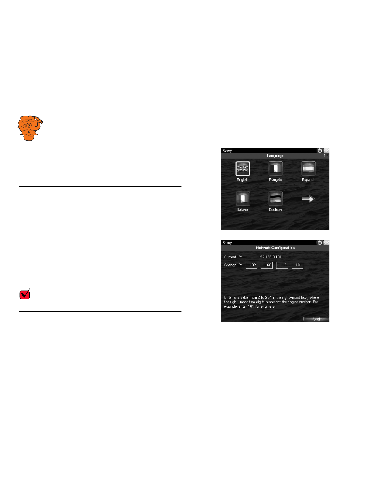
2. Select Installation Language
Select the language that should be used during the installation. There are 3 pages of
language options.
Note:
In this installation manual, all buttons and options are in English.
3. Select IP number
Enter an IP address. The IP address in the factory settings is 192.168.0.101.
The last 2 numbers in the main display's IP address are displayed as the engine num-
ber in the auxiliary display. Example:
• 192.168.0.101 is displayed in the auxiliary display as Engine #1.
• 192.168.0.104 is displayed in the auxiliary display as Engine #4.
The main display IP address can be changed at a later stage. This is done via Short-
cuts > Menu > Settings > Administration > Network Configuration in the main dis-
play.
REQUIREMENT!
The last numeral in the IP address must always be unique to the network.
372 513
372 514
Downloaded from www.Manualslib.com manuals search engine

INSTALLATION
MANUAL
© Scania CV AB 2016, Sweden
Using the main display
03:03 Issue 5.0 en-GB 29
4. Load a configuration
Load a configuration file depending on whether the system is prepared for classifi-
cation or not.
1. Press the bar. See illustration.
2. Select one of the available configuration files:
– Non-classified system with gateway for calculation of fuel consumption.
– Non-classified system.
– Classified system with gateway for calculation of fuel consumption.
– Classified system.
3. Press the arrow button.
5. Finish – Restart
Exit the first power-on wizard by pressing Load and then Restart.
372 515
372 516
372 517
Downloaded from www.Manualslib.com manuals search engine

INSTALLATION
MANUAL
© Scania CV AB 2016, Sweden
Using the main display
03:03 Issue 5.0 en-GB 30
Navigation
Both the main display and auxiliary display are touch screens, without any buttons.
All functions are accessed by pressing the display.
The displays have 5 different display modes:
• Instrument pages
• Select Page
• Shortcut Menu
• Alarm List
• Menu
Different touch areas on the display have different functions. For example, if you
touch the left-hand side of the display on an instrument page, you get to the previous
instrument page. How to navigate:
To get to Press
Select Page in the middle of the display
previous instrument page on the left of the display
next instrument page on the right of the display
Shortcut Menu in the top left-hand corner
Alarm List in the top right-hand corner
Menu a long press (1 s) in the middle of the
display
Downloaded from www.Manualslib.com manuals search engine
 Loading...