


instrumentation
Table of contents
 Loading...
Operator's manual
Scania
Instrumentation
en-GB 2 374 015
Issue 2.0

Introduction . . . . . . . . . . . . . . . . . . . . . . . . . . . . 3
Overview . . . . . . . . . . . . . . . . . . . . . . . . . . . . . . 3
Analogue instrument panel . . . . . . . . . . . . . . . 5
Analogue instrument panel for engines without
SCR system . . . . . . . . . . . . . . . . . . . . . . . . . . . 5
Analogue instrument panel for engines with SCR
system . . . . . . . . . . . . . . . . . . . . . . . . . . . . . . . 6
Display in tachometer . . . . . . . . . . . . . . . . . . . 7
Control panel . . . . . . . . . . . . . . . . . . . . . . . . . . 10
Starter lock . . . . . . . . . . . . . . . . . . . . . . . . . . 10
Engine speed setting 1 and 2. . . . . . . . . . . . . 11
Idling speed adjustment . . . . . . . . . . . . . . . . 12
Limp home mode . . . . . . . . . . . . . . . . . . . . . 12
Remote control . . . . . . . . . . . . . . . . . . . . . . . . . 13
Digital display . . . . . . . . . . . . . . . . . . . . . . . . . 14
Function . . . . . . . . . . . . . . . . . . . . . . . . . . . . 14
Display structure . . . . . . . . . . . . . . . . . . . . . . 15
Favourite screens. . . . . . . . . . . . . . . . . . . . . . 16
Information (4) . . . . . . . . . . . . . . . . . . . . . . . . . 19
Statistics trip (4.1) . . . . . . . . . . . . . . . . . . . . . 19
Performance (4.2) . . . . . . . . . . . . . . . . . . . . . 19
Fault codes (5). . . . . . . . . . . . . . . . . . . . . . . . . . 21
Information about the highlighted fault code 22
Clear fault codes . . . . . . . . . . . . . . . . . . . . . . 22
Update the fault code list . . . . . . . . . . . . . . . 23
Settings (6). . . . . . . . . . . . . . . . . . . . . . . . . . . . . 23
Contrast/brightness (6.1). . . . . . . . . . . . . . . . 23
Button beep (6.2). . . . . . . . . . . . . . . . . . . . . . 24
Language (6.3) . . . . . . . . . . . . . . . . . . . . . . . 24
Units (6.4) . . . . . . . . . . . . . . . . . . . . . . . . . . . 25
Engine (6.5). . . . . . . . . . . . . . . . . . . . . . . . . . 26
Examples of setting. . . . . . . . . . . . . . . . . . . . 32
Base system (6.6) . . . . . . . . . . . . . . . . . . . . . 33
Alarm and fault code generation . . . . . . . . . . 33
Alarms. . . . . . . . . . . . . . . . . . . . . . . . . . . . . . 33
External alarm signal . . . . . . . . . . . . . . . . . . 35
Fault code generation . . . . . . . . . . . . . . . . . . 35
OPM 500 en-GB 2
©
Scania CV AB 2014, Sweden
Introduction
Note:
321 034
1
2
3
4
5
6
7
8
4
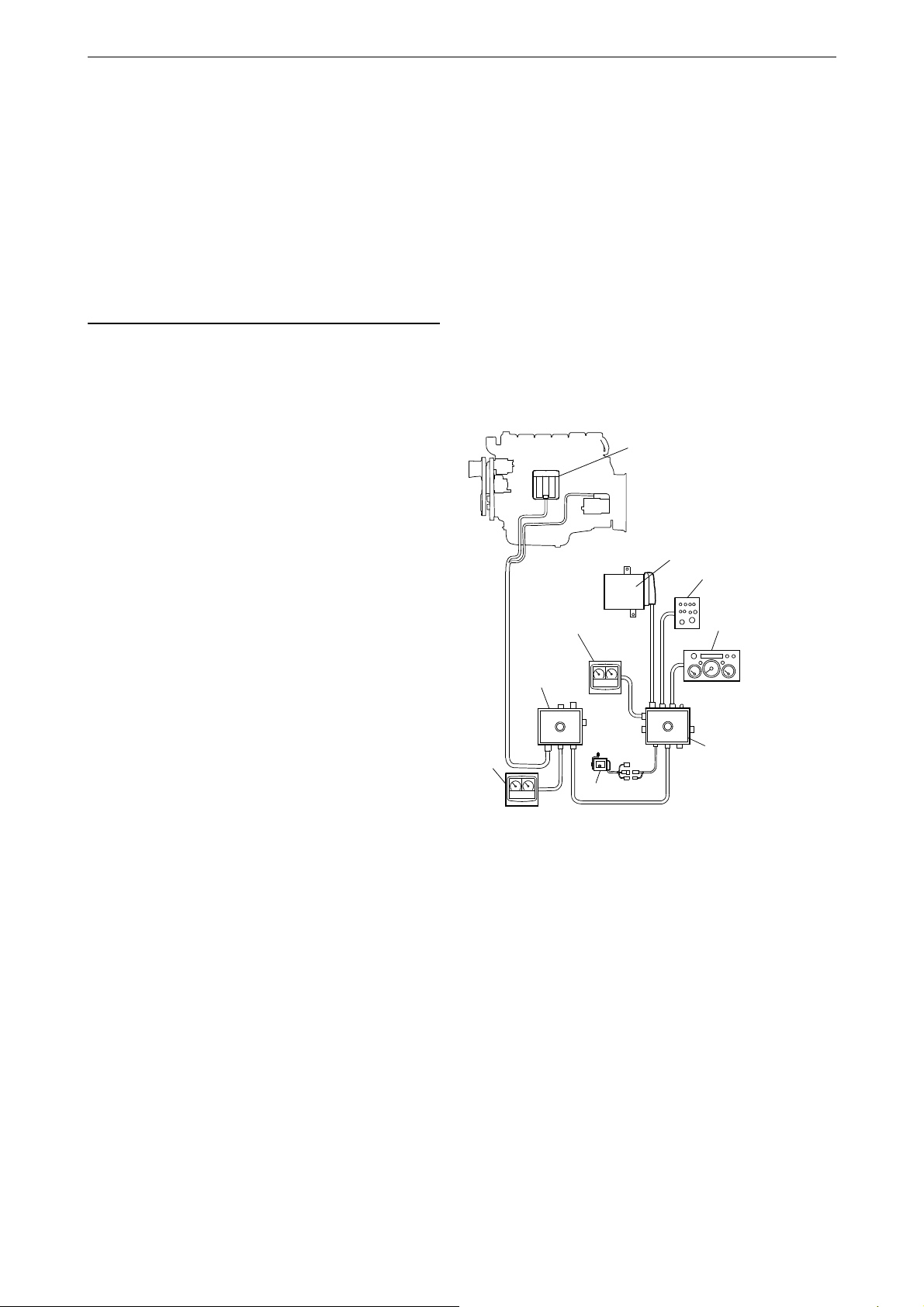
Base system for industrial engines
1. Engine control unit
2. Main junction box
3. Coordinator
4. Digital display
5. Coordinator junction box
6. Control panel
7. Analogue instrument panel
8. Accelerator pedal sensor
This Operator's manual describes operation of
Scania instrumentation.
The information in this manual was correct at the
time of going to press. Scania reserves the right
to make alterations without prior notice.
Always use Scania spare parts for repair work.
Overview
The base system consists of a coordinator, coordinator junction box and main junction box. The
main junction box is connected directly to the engine control unit. There are a number of different
options for the base system that can be connected
to the system:
Introduction
• A digital display together with a control panel
with starter key.
• An analogue instrument panel that can be
used instead of the digital display or together
with it.
• An accelerator pedal sensor.
• A remote control (for marine engines only).
The entire instrumentation system is Plug and
Play which makes it very easy to install.
This Operator's manual only describes the analogue instrument panel, remote control, digital
display and control panel.
OPM 500 en-GB 3
©
Scania CV AB 2014, Sweden

Overview
1
2
3
4
5
6
7
8
9
343 188
Base system for marine engines
1. Engine control unit
2. Remote control
3. Main junction box
4. Accelerator pedal sensor
5. Coordinator junction box
6. Analogue instrument panel
7. Control panel
8. Coordinator
9. Digital display
OPM 500 en-GB 4
©
Scania CV AB 2014, Sweden
Analogue instrument panel
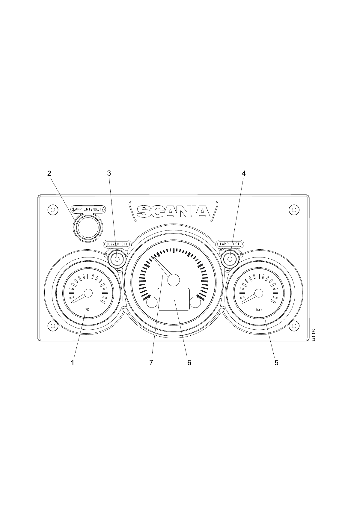
1. Coolant temperature display
2. Adjusting instrument lighting brightness (Lamp intensity)
3. Buzzer deactivation (Buzzer off)
4. Lamp test (Lamp test)
5. Display for oil pressure
6. Display showing engine data, alarms and fault codes
7. Tachometer
The analogue instrument panel has instruments
for reading engine speed, coolant temperature
and oil pressure. It also has hour counting and diagnostic and alarm switches and lamps.
The analogue instrument panel is available in 2
versions, depending on whether the engine is
equipped with an SCR system or not.
Analogue instrument panel
for engines without SCR system
Analogue instrument panel
OPM 500 en-GB 5
©
Scania CV AB 2014, Sweden

Analogue instrument panel
1. Coolant temperature display
2. Adjusting instrument lighting brightness (Lamp intensity)
3. Buzzer deactivation (Buzzer off)
4. Lamp test (Lamp test)
5. Display for oil pressure
6. Display showing engine data, alarms and fault codes
7. Tachometer
8. Warning lamp for low reductant level
9. Warning lamp for SCR system faults.
for engines with SCR system
Analogue instrument panel
OPM 500 en-GB 6
©
Scania CV AB 2014, Sweden
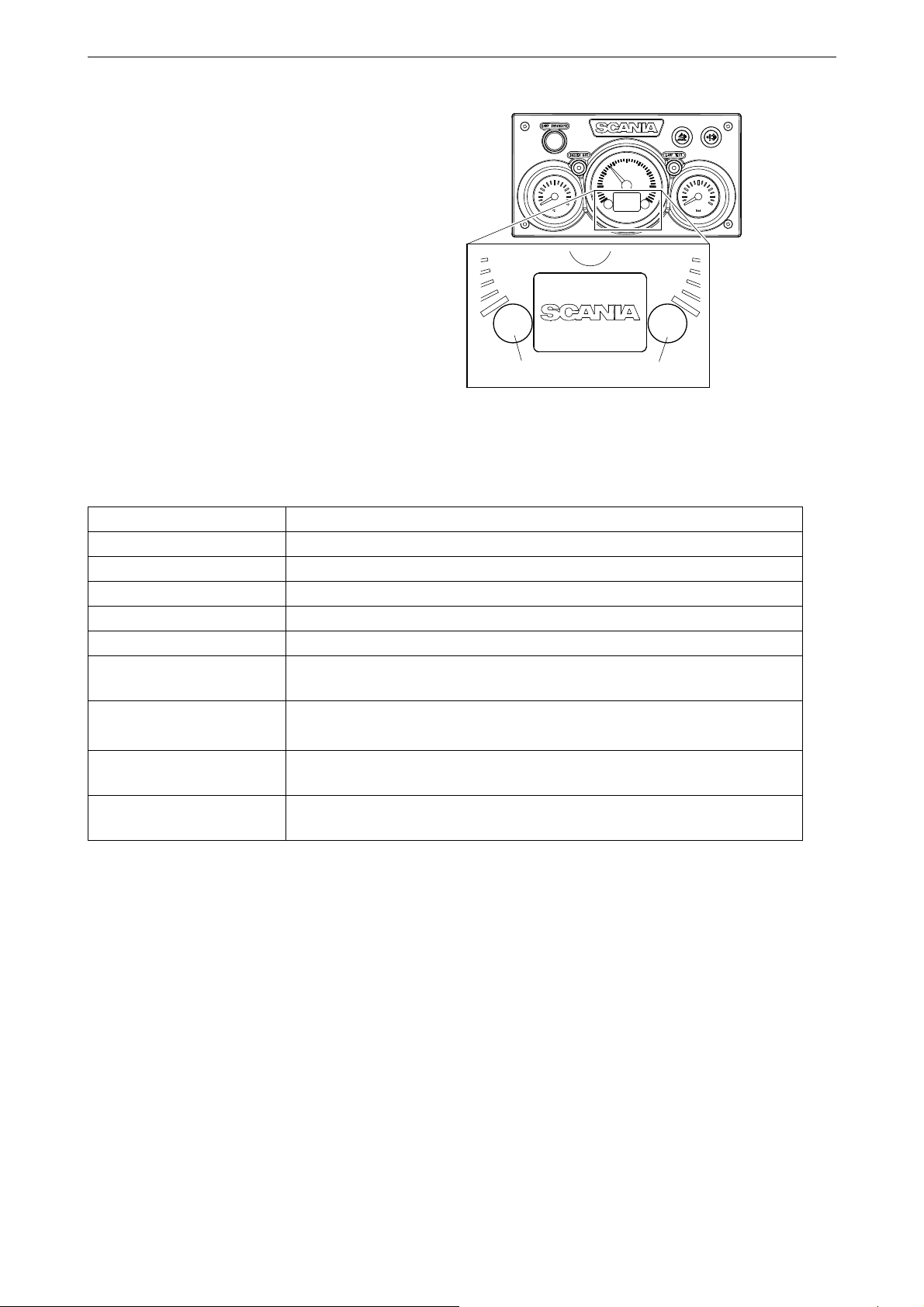
Display in tachometer
322 253
12
Integrated in the tachometer is a digital display
that shows engine data, alarms and fault codes.
Button 1 displays the previous page and button 2
displays the next page. The table below describes
how to go down a level in the structure.
Engine data shown on the display
Analogue instrument panel
Engine data Explanation
Coolant temperature
Oil pressure
Fuel level
Fuel consumption
Charge air pressure
Trip meter
Adjusting instrument lighting brightness
Reset the trip meter by holding buttons 1 and 2 down at the same time for
3 seconds.
Reduce the brightness by holding button 1 down for 3 seconds
Increase the brightness by holding button 2 down for 3 seconds
Settings No settings can be changed. The only available language is English and the
only available unit is metric
Fault codes Display an explanation of active fault codes by holding buttons 1 and 2
down at the same time for 3 seconds.
OPM 500 en-GB 7
©
Scania CV AB 2014, Sweden
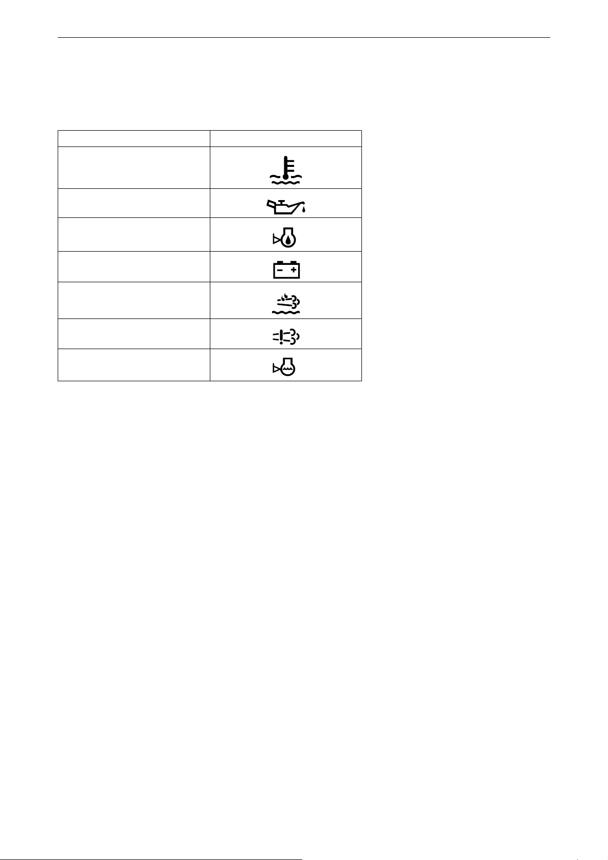
Alarms
On the display in the tachometer, the following
alarms are shown:
Alarm Symbol
High coolant temperature
Low oil pressure
Analogue instrument panel
Oil level too high or low
1
Alternator not charging
Low reductant level
SCR fault
1
Low coolant level
1. Depending on how the engine is equipped.
1
1
OPM 500 en-GB 8
©
Scania CV AB 2014, Sweden
Fault codes
343 928
21
322 255
92.2
Coolant [C˚]
322 256
DTC:
EMS
11
1/16
2100!
1
2
3
4
5
6
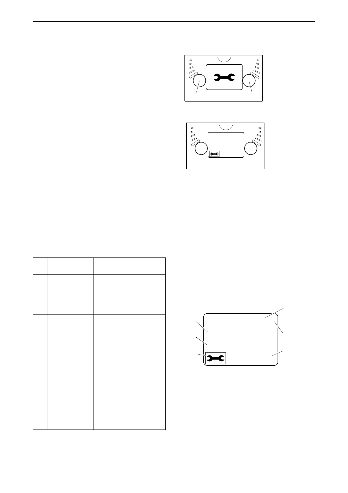
When a fault code is generated, a symbol is
shown on the display in the tachometer. Acknowledge the fault code by pressing button 1 or
2.
Once the fault code has been acknowledged, the
fault code symbol remains (refer to illustration)
as long as the fault code is active.
Analogue instrument panel
Fault code description
If you want to see a more detailed description of
the fault code, hold buttons 1 and 2 down at the
same time for 3 seconds.
The fault code contains the following information:
Pos.Information Explanation
1 Shows the con-
trol unit in
which the fault
code was registered
2 Counter Shows how many times
3 Fault code sym-
bol
4 Fault code Shows the fault code in
5 Active fault
code
6 Page Shows which page is ac-
The engine management
system (EMS), coordinator (COO) or SCR control
unit (SCR)
the displayed fault has occurred
hexadecimal form
! is shown if the fault code
is active. If the fault code
is inactive, no ! is displayed
tive and how many pages
there are
OPM 500 en-GB 9
©
Scania CV AB 2014, Sweden

Control panel
23 4 5
19 8
6
7
321 169
The engine is started and shut down from the
control panel, which has a starter lock and functions for engine speed setting and idling setting.
1. Control for adjusting engine speed and idling
speed
2. Control for storing new engine speed and
idling speed
3. Control for activating engine speed setting 1
4. Control for activating engine speed setting 2
5. Control for deactivating engine speed setting
1 (marine engines) or 2 (industrial engines).
6. Indicator lamp for limp home throttle con-
1
trol
7. Limp home throttle control (Limp home)
8. Starter lock
9. Indicator lamp for active panel (Active pan-
el)
1
Control panel
Starter lock
The starter lock (8) is used to start and shut down
the engine.
Position 0: The engine electrical system and the
engine are switched off.
Position 1: The engine electrical system is activated.
Position 2: The starter motor is activated.
1. Only available for marine engines.
OPM 500 en-GB 10
©
Scania CV AB 2014, Sweden

Engine speed setting 1 and 2
Note:
23 4 5
19 8
6
7
321 169
Engine speed setting 1 is an engine speed set between high and low idling. High and low idling
vary depending on the engine. The engine speed
is set with control 3.
Engine speed setting 2 is an engine speed that is
set between 450 and 2,000 rpm. The engine
speed is set with control 4.
For both engine speed settings, torque limitation
can be set via either the digital display or using
SDP3. The engine speed settings are isochronous, i.e. the engine speed is held constant irrespective of load.
When either of the engine speed settings is activated, the engine speed goes up or down to the
last saved engine speed.
Control panel
In order to activate engine speed setting 1 or 2,
the engine must be running, the active panel indicator lamp must be on and the throttle must be
at 0%.
Change the engine speed:
• Activate engine speed setting 1 or 2 with control 3 or 4.
• Adjust engine speed up or down with control
1.
• Save the new setting by holding control 2
down for 3 seconds.
If the setting is not saved, the engine uses the last
saved value next time engine speed setting is activated.
This is how to switch off the engine speed settings:
• Press control 5, touch the accelerator pedal or
switch off the engine.
OPM 500 en-GB 11
©
Scania CV AB 2014, Sweden
Loading...