


Installation manual
Engine
Industrial engines
DC09, DC13, DC16
OC16
333 291
01:01 Issue 8.0 en-GB
© Scania CV AB 2016, Sweden
Downloaded from www.Manualslib.com manuals search engine

INSTALLATION MANUAL
Engine suspension.................................................................................................... |
3 |
Design requirements............................................................................................ |
3 |
Flexible engine suspension.................................................................................. |
4 |
Rigid engine suspension...................................................................................... |
5 |
Permissible installation and operating angles ..................................................... |
6 |
Flywheel housings............................................................................................... |
7 |
Generator set dynamics ....................................................................................... |
8 |
Lifting the engine ................................................................................................ |
8 |
Accessibility for maintenance and repairs ............................................................ |
9 |
Installation requirements ..................................................................................... |
9 |
Clearances ......................................................................................................... |
11 |
Engine alignment................................................................................................... |
12 |
Flexible coupling............................................................................................... |
12 |
Aligning engine and shafts................................................................................ |
13 |
Power transmission ............................................................................................... |
18 |
Flexible coupling............................................................................................... |
18 |
Friction clutch ................................................................................................... |
18 |
Transmission types ................................................................................................ |
20 |
Mechanical transmissions ................................................................................. |
20 |
Belt transmissions ............................................................................................. |
20 |
Power take-offs ...................................................................................................... |
22 |
Front-mounted power take-offs......................................................................... |
22 |
Side-mounted power take-offs .......................................................................... |
25 |
Air compressor ...................................................................................................... |
31 |
Torsional oscillations............................................................................................. |
32 |
Data for torsional oscillation calculation .......................................................... |
33 |
Torsional oscillation calculations from Scania................................................. |
34 |
General tightening torques for screw joints ....................................................... |
35 |
Specification of normal tightening torques....................................................... |
35 |
Tightening torques ............................................................................................ |
36 |
Sticker “Powered by Scania”............................................................................... |
39 |
01:01 Issue 8.0 en-GB |
2 |
© Scania CV AB 2016, Sweden
Downloaded from www.Manualslib.com manuals search engine

INSTALLATION
MANUAL
Engine suspension
Design requirements
The type of engine suspension that is appropriate varies for different engine installations. In general, the following applies:
•The engine suspension should be designed for the forces it is exposed to, both continuously and momentarily during operation. Such forces are reaction forces from the transmitted torque and in some cases longitudinal acceleration, retardation and reaction forces in the engine.
•Both the engine suspension and the engine bed should be designed so that there are no resonant oscillations within the engine speed range. They should also be designed so that annoying vibrations from the engine are not transmitted to the surroundings.
•The engine bed location and the engine suspension must be designed so that the permissible angles of inclination for the engine are not exceeded. See the table in the Permissible installation and operating angles section.
•The engine suspension and engine bed should be designed in a way which allows access for maintenance and repairs.
 IMPORTANT!
If the angles of inclination are exceeded, lubrication system performance will deteriorate, which can cause damage to the engine or reduce its service life.
There are two standard engine suspension designs:
•flexible engine suspension
•rigid engine suspension.
01:01 Issue 8.0 en-GB
© Scania CV AB 2016, Sweden
Downloaded from www.Manualslib.com manuals search engine
Engine suspension
3
INSTALLATION MANUAL
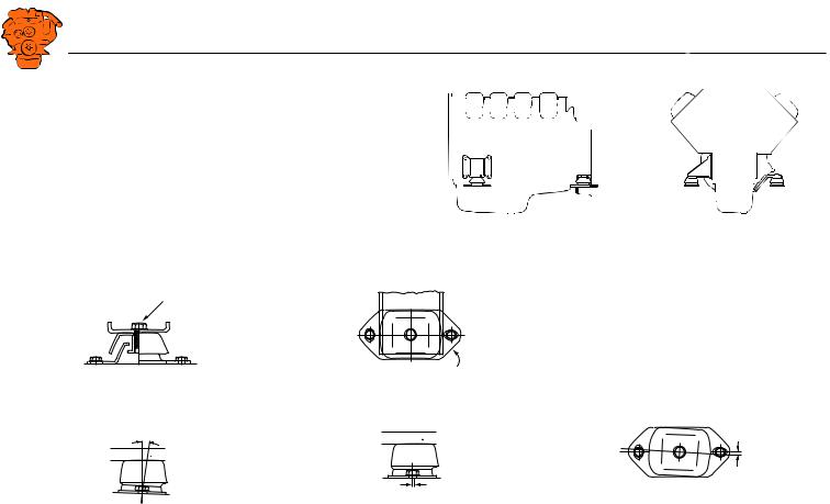
Flexible engine suspension
Flexible engine suspension dampens vibrations more effectively than rigid engine suspension. Flexible engine suspension does not require such careful alignment of the engine as rigid engine suspension. However, flexible engine suspension does not absorb longitudinal and lateral forces in the engine to the same extent as rigid engine suspension.
Insulators
Cushyfloat insulators with hardness 55 or 65 Shore are delivered as standard.
160±10 Nm
310 404
Examples of flexible engine suspension.
310 405
55
55 alt. 65
Tightening torque. |
Hardness marking. |
Engine suspension
334 280
max 1°  407310
The engine bracket and frame or engine bed should be parallel.
01:01 Issue 8.0 en-GB
 310 408
0°
The vertical centre lines should coincide laterally.
© Scania CV AB 2016, Sweden
|
0° |
55 |
406 |
|
310 |
The upper and lower parts of the insulators should be parallel longitudinally.
4
Downloaded from www.Manualslib.com manuals search engine
INSTALLATION
MANUAL
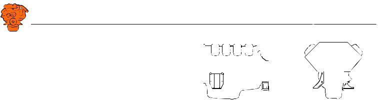
Rigid engine suspension
A rigid engine suspension can absorb greater forces in all directions than flexible engine suspension. It requires highly accurate alignment of the engine in relation to the driven unit. On the other hand, it requires no special flexibility in the hoses, pipes and controls connected to the engine.
A rigid engine suspension can be used in engine installations where vibration causes no significant problems and where other characteristics make it desirable.
Even with a rigid engine suspension, the transmission of vibration to the engine bed can be kept low if the masses of the engine bed and connected parts are large in relation to the mass of the engine.
It is also possible to construct flexible engine suspension between the frame and the engine bed to reduce the transmission of vibration to the engine bed.
Engine suspension
344 281
Examples of rigid engine suspension.
01:01 Issue 8.0 en-GB |
5 |
© Scania CV AB 2016, Sweden
Downloaded from www.Manualslib.com manuals search engine

INSTALLATION
MANUAL
Engine suspension
Permissible installation and operating angles
Maximum installation angle means maximum permissible installation angle for an engine relative to the horizontal plane. The angle indicates the limit for engine inclination during continuous operation.
Maximum operating angle means maximum permissible angle of inclination for an engine in operation and with minimum oil level. The angle may only be used for short periods. The given maximum forward or rearward operating angles are not applicable to their full extent if the engine is inclined laterally at the same time.
Engine type |
Type of oil sump |
Max. installation angle |
Max. operating angle |
Oil capacity (litres) |
|||
|
|
Inclination rear- |
Inclination lat- |
Inclination rear- |
Inclination lat- |
Min. |
Max. |
|
|
wards and for- |
erally |
wards and for- |
erally |
|
|
|
|
wards |
|
wards |
|
|
|
DC09 |
Deep front without ladder frame |
12° |
12° |
30° |
30° |
31 |
36 |
DC09 |
Low |
12° |
12° |
25° |
30° |
28 |
35 |
DC13 |
Deep front without ladder frame |
12° |
12° |
30° |
30° |
30 |
36 |
DC13 |
Deep front with ladder frame |
12° |
12° |
30° |
30° |
39 |
45 |
DC13 |
Low |
12° |
12° |
25° |
30° |
28 |
34 |
DC13 |
With deep centre part |
12° |
12° |
35° |
45° |
33 |
39 |
DC16, OC16 |
Deep front without ladder frame |
12° |
10° |
25° |
30° |
40 |
48 |
DC16 |
Low |
12° |
10° |
25° |
30° |
29 |
37 |
01:01 Issue 8.0 en-GB |
6 |
© Scania CV AB 2016, Sweden
Downloaded from www.Manualslib.com manuals search engine

INSTALLATION
MANUAL
Flywheel housings
Silumin housings are supplied as standard on all industrial engines. The maximum permissible bending torque for a silumin housing is 10,000 Nm. This presumes that there are no axial loads from, for example, the propeller shaft, abnormal G forces or vibration.
For certain engine types, it is also possible to select a nodular iron flywheel housing. Nodular iron housings can dampen vibrations at certain engine speeds but increase vibrations at other engine speeds. Nodular iron is stronger than silumin and can therefore tolerate greater bending and torsional forces.
The stronger nodular iron housings are recommended in installations where transport causes serious stress on the flywheel housing, such as in dumper type trucks and generator sets with high outputs.
If it is difficult to determine the size and nature of the load, contact your nearest Scania distributor.
01:01 Issue 8.0 en-GB
© Scania CV AB 2016, Sweden
Downloaded from www.Manualslib.com manuals search engine
Engine suspension
7
INSTALLATION
MANUAL
Engine suspension
Generator set dynamics
If vibration levels in a generator set are too high, it could be due to resonance. This may be because resonant frequencies of the receiving system are the same as the frequency of the torque and disrupting power pulses that arise during normal operation of combustion engines with a crankshaft. The resonant frequencies of the system depend in turn on the mass and rigidity of component parts.
It is the responsibility of the installer to check that no resonant frequencies or vibration levels that could damage component parts are found anywhere in the engine installation.
The measurement and evaluation of vibrations in static parts is described in international standards. See ISO 8528-9.
1 |
2 |
3 |
4 |
|
|
|
|
|
|
|
|
|
|
|
|
|
|
|
|
|
|
|
|
|
|
|
|
|
|
|
|
|
|
|
|
|
|
|
|
|
|
|
|
|
|
|
|
|
|
|
|
|
|
|
|
|
|
|
|
|
|
|
|
|
|
|
|
5 |
||||||
|
|
|
|
|
|
|
|||||||
|
|
|
|
|
|
|
|||||||
6 |
|
|
|
|
6 |
|
|
|
|||||
344 282
Lifting the engine
 WARNING!
The engine lifting eyes are dimensioned for lifting the engine only, not the engine together with connected equipment or frame!
Example of generator set.
1.Engine.
2.Flywheel housing.
3.Adapter.
4.Generator.
5.Engine bed.
6.Vibration insulators.
01:01 Issue 8.0 en-GB |
8 |
© Scania CV AB 2016, Sweden
Downloaded from www.Manualslib.com manuals search engine

INSTALLATION
MANUAL
Accessibility for maintenance and repairs
Accessibility for maintenance and repairs
Installation requirements
The installer is responsible for ensuring accessibility for maintenance and repairs.
Note:
There must be sufficient space at installation so that standard times for maintenance and repairs can be attained.
The following requirements for accessibility must be met:
•Canopies and connected components must be designed so that the engine can be removed and fitted relatively easily.
•In the case of static engine installations, there should be permanent securing points for lifting devices above the unit.
•The fuel system must be easily accessible for maintenance and bleeding.
•It should be possible to read the graduations on the flywheel when adjusting valves and unit injectors.
•It should be possible to remove and fit the cylinder head, rocker covers and pushrods while leaving the engine in place.
•It must be possible to remove the oil sump in order to renew cylinder liners or pistons with the engine in place.
01:01 Issue 8.0 en-GB |
9 |
© Scania CV AB 2016, Sweden
Downloaded from www.Manualslib.com manuals search engine

INSTALLATION
MANUAL
Accessibility for maintenance and repairs
•It should be easy to fill and drain oil. In addition, the oil dipstick must be easily accessible.
•Centrifugal oil cleaners and oil filters must be easy to access for maintenance and for renewal.
•It should be easy to fill and drain coolant.
•Engine air filters must be located so that they are easy to access for the renewal of filter elements.
It must also be easy to carry out maintenance on the following components:
•Turbocharger
•Starter motor
•Alternator
•Coolant pump
•Radiator
•Cooling fan
•Clutch
•Batteries
•Crankcase ventilation filter
For gas engines, it must also be easy to carry out maintenance on the following components:
•Spark plug
•Flame arrestor
•Gas mixer insert
•Electric throttles
•Gas regulator
•Lambda sensor
01:01 Issue 8.0 en-GB |
10 |
© Scania CV AB 2016, Sweden
Downloaded from www.Manualslib.com manuals search engine

INSTALLATION
MANUAL
Accessibility for maintenance and repairs
Clearances |
|
|
|
|
|
|
|
|
|
|
|
|
|
|
|
|
|
|
|
|
|
|
|
|
|
|
|
|
|
|
|
||
|
|
|
|
|
|
|
|
|
A |
|
|
|
|
|
|
|
|
|
|
|
|
|
|
|
|
|
|
|
|
||||
The most important clearances are shown in the table and illustrations. The specified |
|
|
|
|
|
|
|
|
|
|
|
|
|
|
|
|
|
|
|
|
|
|
|
|
|
|
|||||||
|
|
|
|
|
|
|
|
|
|
|
|
|
|
|
|
|
|
|
|
|
|
|
|
|
|
|
|
|
|
||||
measurements apply to the largest standard equipment. |
|
|
|
|
|
|
|
|
|
|
|
|
|
|
|
|
|
|
|
|
|
|
|
|
|
|
|
|
|
|
|
|
|
|
|
|
|
|
|
|
|
|
|
|
|
|
|
|
|
|
|
|
|
|
|
|
|
|
|
|
|
|
|
|
|
|
|
Meas |
Clearance in mm |
|
|
For maintenance or renewal of |
|
|
|
ure- |
DC09 |
DC13 |
DC16 |
OC16 |
|
|
|
ment |
|
|
|
||||
A |
150 |
150 |
150 |
380 |
cylinder liner, cylinder head, etc. |
F |
F |
B |
250 |
260 |
260 |
260 |
oil sump1 |
|
|
F |
400 |
400 |
400 |
500 |
various units |
|
|
1. If the oil sump has a special design, these values do not apply. |
|
B |
|||||
|
|
|
|
|
|
|
|
F
344 285
Clearances for DC09 and DC13.
F
|
|
A |
|
|
|
|
|
|
|
|
|
|
|
|
|
|
|
|
|
|
|
A |
|
||
|
|
|
|
|
|
|
|
|
|
|
|
|
|
|
|
|
|
|
|
|
|
||||
|
|
|
|
|
|
|
|
|
|
|
|
|
|
|
|
|
|
|
|
|
|
||||
|
|
|
|
|
|
|
|
|
|
|
|
|
|
|
|
|
|
|
|
|
|
|
|
||
|
F |
|
|
|
|
|
|
|
|
|
|
|
|
|
|
|
|
|
|
|
|
|
|
F |
|
|
|
|
|
|
|
|
|
|
|
|
|
|
|
|
|
|
|
|
|
|
|
|
|
||
|
|
|
|
|
|
|
|
|
|
|
|
|
|
|
|
|
|
|
|
|
|
|
|
||
|
|
|
|
|
|
|
|
|
|
|
|
|
|
|
|
|
|
|
|
|
|
|
|
||
|
|
|
|
|
|
|
|
|
|
|
|
|
|
|
|
|
|
|
|
|
|
|
|
||
|
|
|
|
|
|
|
|
|
|
|
|
|
|
|
|
|
|
|
|
|
|
|
|
||
|
|
|
|
|
|
|
|
|
|
|
|
|
|
|
|
|
|
|
|
|
|
|
|||
|
|
|
|
|
|
|
|
|
|
|
|
|
|
|
|
|
|
|
|
|
|
|
|
|
|
|
|
|
|
|
|
|
|
|
|
|
|
|
|
|
|
|
|
|
|
|
|
|
|
|
|
|
|
|
|
|
|
|
|
|
|
|
|
|
|
|
|
|
|
|
|
|
|
|
|
|
|
|
|
|
|
|
|
||||||||||||||||||||
|
|
|
|
B |
|
|
|||||||||||||||||||
|
|
|
|
|
|
|
|
|
|
|
|
|
|
|
|
|
|
|
|
|
|
|
|
|
|
Clearances for DC16 and OC16.
01:01 Issue 8.0 en-GB
© Scania CV AB 2016, Sweden
F
344 286
11
Downloaded from www.Manualslib.com manuals search engine

INSTALLATION
MANUAL
Engine alignment
The alignment of the engine in relation to the driven unit is very important in order to prevent malfunctions. Otherwise there is a risk of vibration and serious stress to the crankshaft, engine brackets, drive shaft and coupling, causing damage which is costly to repair.
Alignment should be checked regularly on certain vibration-sensitive engine installations. Adjust engine alignment with shims between the engine bed and the engine suspension.
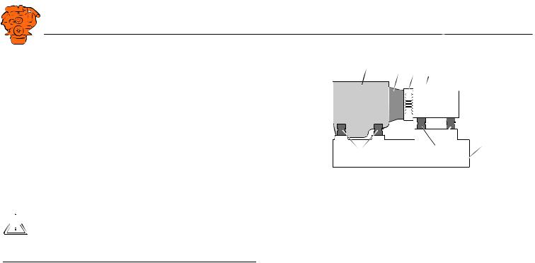
Flexible coupling
The alignment requirements are reduced if a flexible coupling is installed between the engine and the driven unit. Refer to the data on the flexible coupling concerned for permissible deviations.
Flexible coupling allows a certain angular displacement towards the output shaft. It also has an effect of evening out irregularities in torque and therefore counteracts the tendency towards torsional oscillation. The correct choice of rubber hardness reduces the stress on the driven units.
Relatively large deviations are permissible with flexible couplings. However, alignment should be as accurate as possible to achieve low vibration and a long service life on the coupling.
01:01 Issue 8.0 en-GB
© Scania CV AB 2016, Sweden
Downloaded from www.Manualslib.com manuals search engine
Engine alignment
12
 Loading...