


IMPORTANT INFORMATION
When working on the engine. e.g. adjusting drive belts, changing oil or adjusting the clutch,
!it is important not to start the engine. There is a risk of damaging the engine but, more importantly, there is a
SERIOUS DANGER OF INJURY
For this reason, always secure the starter device or detach a battery lead before working on the engine.
This is especially important if the engine has a remote starter or automatic start.
This warning symbol and text is reproduced beside those maintenance points where it is especially important to consider the risk of injury.
START-UP REPORTWARRANTY
When the start-up report has been filled in and sent to Scania, you have a 1 year warranty from the date of startup. Also fill in the information below as this can make things easier if you need to contact a service workshop or the like.
Engine number
Start-up date
User’s name and address
Engine type
Variant
Engine type and variant are indicated on the engine type plate
Operator’s Manual
DI14 69 (750 hp)
DI14 82 (800 hp)
Marine engine
opm96-750 en |
1 588 538 |
2001-05:1
Industrial & Marine Engines

FOREWORD
This instruction manual describes the operation and maintenance of Scania marine engine DI14 69 (750 hp) and DI14 82 (800 hp). The instructions apply to this engine type in program 96 with effect from engine number 5 564 900.
The engines are direct-injection, liquid-cooled, four-stroke, V8 diesel engines with 2 turbochargers. This engine has 2 charge air coolers connected to the internal cooling system and a charge air cooler cooled by seawater, see also page 10.
The engines feature an internal cooling system with a heat exchanger cooled by seawater.
The engine type has electronic control of the injection system’s governor to optimize engine performance and such important operating factors as fuel consumption and exhaust emissions. Called DEC2 (Digital Electronic Control), the electronic control system is described in greater detail on page 12.
A common application is as the propulsion unit in larger leisure boats.
The normal output setting of the engine (performance code) is indicated on the type plate, see page 10.
Note Only standard components are described in the instruction manual. For special equipment we would refer you to the appropriate manufacturer’s instructions.
In order to obtain the best value and service life from your engine, there are several points to bear in mind:
-Read through the Instruction Manual before starting to use your engine. Even those experienced with Scania engines may find new information in this manual.
-Follow the maintenance instructions. Maintenance carried out according to these instructions forms the basis of reliable operation and a long service life.
-Pay special attention to the safety information beginning on page 6.
-Get to know your engine so that you know what it can do and how it works.
-When necessary, always turn to an authorised Scania workshop. These have special tools, genuine parts and staff with training and practical experience of Scania engines.
Note Always use genuine Scania parts in service and repair to keep the engine operating correctly.
The particulars in this manual were applicable at the time it was printed. We reserve the right to introduce changes without prior notice.
Scania CV AB
Industrial and Marine engines
S-151 87 Södertälje
During the warranty period, only use genuine Scania parts in service and repair for the warranty to be valid.
2 |
© Scania Industrial & Marine Engines |
2001-05:1 |

LIST OF CONTENTS
FOREWORD . . . . . . . . . . . . . . . . . . . . . . . . . . 2
LIST OF CONTENTS . . . . . . . . . . . . . . . . . 3
ENVIRONMENTAL RESPONSIBILITY . . . . . . 4 CERTIFIED ENGINES . . . . . . . . . . . . . . . . . . . . 5 SAFETY DETAILS . . . . . . . . . . . . . . . . . . . . . . . 6 Safety precautions for operation . . . . . . . . . . . . 7 Safety precautions for handling materials . . . . . 8 Safety precautions for care and maintenance . . 8
TYPE DESIGNATIONS . . . . . . . . . . . . . . . 10 DEC2 CONTROL SYSTEM . . . . . . . . . . . . 12
STARTING AND RUNNING . . . . . . . . . . . 18
AT FIRST START . . . . . . . . . . . . . . . . . . . . . . . 18 CHECKS BEFORE RUNNING . . . . . . . . . . . . . 19 STARTING THE ENGINE . . . . . . . . . . . . . . . . 19 At temperatures below 0 °C: . . . . . . . . . . . . . . 20 RUNNING . . . . . . . . . . . . . . . . . . . . . . . . . . . . . 21 Engine speed . . . . . . . . . . . . . . . . . . . . . . . . . . 21 Coolant temperature . . . . . . . . . . . . . . . . . . . . 21 Oil pressure . . . . . . . . . . . . . . . . . . . . . . . . . . . 22 STOPPING THE ENGINE . . . . . . . . . . . . . . . . . 22 CHECKS AFTER RUNNING . . . . . . . . . . . . . . 23
MAINTENANCE . . . . . . . . . . . . . . . . . . . . . 24
ENGINES WITH FEW HOURS OF OPERATION . . . . . . . . . . . . . . . . . . . . . . . . . . . 24
MAINTENANCE SCHEDULE . . . . . . . . . . . . . 25
LUBRICATION OIL SYSTEM . . . . . . . . . 26
OIL GRADE . . . . . . . . . . . . . . . . . . . . . . . . . . . . 26 Oil analysis . . . . . . . . . . . . . . . . . . . . . . . . . . . 26 CHECKING OIL LEVEL . . . . . . . . . . . . . . . . . . 27 OIL CHANGE . . . . . . . . . . . . . . . . . . . . . . . . . . 27
Maximum oil sump angles of inclination
when in operation . . . . . . . . . . . . . . . . . . . . . . 27 CLEANING THE OIL CLEANER . . . . . . . . . . 28 CHANGING THE TURBO FILTER . . . . . . . . . 30
COOLING SYSTEM . . . . . . . . . . . . . . . . . . 30
CHECKING COOLANT LEVEL . . . . . . . . . . . 30
CHECKING CORROSION PROTECTION RODS . . . . . . . . . . . . . . . . . . . . . . . . . . . . . . . . . 31
CHECKING SEAWATER PUMP IMPELLER . 31 CHECKING COOLANT . . . . . . . . . . . . . . . . . . 32 Checking glycol content . . . . . . . . . . . . . . . . . 32 Checking Protection against corrosion . . . . . . 34 Changing the coolant . . . . . . . . . . . . . . . . . . . 34
CLEANING THE COOLING SYSTEM . . . . . . 35 External cleaning . . . . . . . . . . . . . . . . . . . . . . 35 Internal cleaning . . . . . . . . . . . . . . . . . . . . . . . 38 Preventive replacement of coolant pump gear 38
AIR CLEANER . . . . . . . . . . . . . . . . . . . . . . . 39
TEST READING
LOW PRESSURE INDICATOR . . . . . . . . . . . . 39
CLEANING OR CHANGING THE
FILTER INSERT . . . . . . . . . . . . . . . . . . . . . . . . 39
FUEL SYSTEM . . . . . . . . . . . . . . . . . . . . . . . 41
CHECKING THE FUEL LEVEL . . . . . . . . . . . . 41 CHANGING THE FUEL FILTER . . . . . . . . . . . 41 CHECKING INJECTORS . . . . . . . . . . . . . . . . . 42
ELECTRICAL SYSTEM . . . . . . . . . . . . . . . 43
CHECKING THE ELECTROLYTE LEVEL IN BATTERIES . . . . . . . . . . . . . . . . . . . . . . . . . . . . 43
CHECKING THE CHARGE STATE
OF THE BATTERIES . . . . . . . . . . . . . . . . . . . . 43 CLEANING BATTERIES . . . . . . . . . . . . . . . . . 43
CHECKING THE COOLANT LEVEL MONITOR 44
MISCELLANEOUS . . . . . . . . . . . . . . . . . . . 45
CHECK/TENSION
V-BELTS . . . . . . . . . . . . . . . . . . . . . . . . . . . . . . 45
LOOK FOR LEAKS, |
|
REMEDY AS NECESSARY . . . . . . . . . . . . . . |
46 |
CHECKING/ADJUSTING
VALVE CLEARANCE . . . . . . . . . . . . . . . . . . . 47
CHANGING (OR CLEANING) VALVES
FOR CLOSED CRANKCASE VENTILATION 48
LONG-TERM STORAGE . . . . . . . . . . . . . . 49
Preservative fuel . . . . . . . . . . . . . . . . . . . . . . . 49 Preservative oil . . . . . . . . . . . . . . . . . . . . . . . . 50 Preparations for storage . . . . . . . . . . . . . . . . . 50 Batteries . . . . . . . . . . . . . . . . . . . . . . . . . . . . . 51 Taking out of storage . . . . . . . . . . . . . . . . . . . 51
TECHNICAL DATA . . . . . . . . . . . . . . . . . . 52
FUEL . . . . . . . . . . . . . . . . . . . . . . . . . . . . . . 54
ALPHABETICAL INDEX . . . . . . . . . . . . . . 55
2001-05:1 |
© Scania Industrial & Marine Engines |
3 |

ENVIRONMENTAL RESPONSIBILITY
Scania has always been at the forefront in the development and production of environmentally safe engines.
We have made great progress in reducing harmful exhaust emissions to be able to meet the stringent emission standards that are mandatory for almost all markets.
We have done this without compromising the high quality of Scania industrial and marine engines in terms of performance and cost effective operation.
To maintain these superior properties throughout the life of the engine it is important that the operator/owner follows the instructions of this manual as regards operation, maintenance and choice of fuel and lubricants.
To further contribute to protecting the environment in service, maintenance and repair, ensure that harmful waste (oil, fuel, coolant, filters, batteries etc.) is disposed of and destroyed according to applicable local regulations.
This operator’s manual contains highlighted text urging you to protect the environment in different service and maintenance operations.
Refer to example
Always use suitable containers  to avoid spillage when bleeding
systems or renewing components.
4 |
© Scania Industrial & Marine Engines |
2001-05:1 |

CERTIFIED ENGINES
An emission certified engine has been approved according to a specific certification standard. The certified engines delivered by Scania meet the most compelling emission standards in the European (EU) and non-European (USA) markets.
Scania guarantees that all engines of a certified engine type that are delivered, correspond to the engine approved for certification.
The engine is fitted with a certification plate, stating according to which certification rules (standard) the engine has been approved. Refer to page 10.
The following is required for the engine to meet the emission standards after being commissioned:
-Service and maintenance must be performed according to this Operator’s Manual.
-Only genuine Scania parts must be used.
-Service work on the injection equipment must be performed by an authorized Scania workshop.
-The engine must not be modified with equipment not approved by Scania.
-Seals and setting data may only be broken/modified after approval by Scania, Södertälje. Changes should only be made by qualified personnel.
-Changes affecting the exhaust system and intake system must be approved by Scania.
Otherwise, follow the instructions in this manual for operation, care and maintenance of the engine. Also observe the safety precautions described in the following four pages.
Important! If service and maintenance are not performed as stated above, Scania cannot guarantee that the engine corresponds to the certified configuration and will not assume liability for any damage occurring.
2001-05:1 |
© Scania Industrial & Marine Engines |
5 |
SAFETY DETAILS
General
This Operator’s Manual contains safety information that must be observed in order to avoid personal injuries and damage to the product or property. Refer to page 1.
The text boxes to the right on the pages provide information that is important for the proper operation of the engine and to avoid damage to the engine. Failure to follow these instructions may void the warranty.
Refer to example. 

Corresponding texts may also appear in the text column, headed Caution! or
Important
The warning text in text boxes to the right on the pages provided with a warning triangle and headed WARNING is extremely important and warns of serious defects to the engine or improper handling that may lead to personal injury.
Refer to example 

The safety precautions that must be observed in the operation and maintenance of Scania engines are compiled on the following three pages. The corresponding text is also often stated next to the maintenance step concerned, shown with different degrees of significance as described above.
All items are marked with a ! to highlight the importance of reading each item in the section.
A general safety rule is that no smoking is allowed:
•Near the engine and the engine bay
•When refuelling and near the filling station
•When work is performed on the fuel system
•Near flammable or explosive materials (fuel, oils, batteries, chemicals etc.)
Only use Scania genuine fuel filter.
Immobilise the starting device when working on the engine.
If the engine starts out of control, there is a SERIOUS RISK
OF INJURY.
6 |
© Scania Industrial & Marine Engines |
2001-05:1 |

Safety precautions for operation
 Daily inspection
Always perform visual inspection of the engine and engine bay before the engine is started and when the engine has been stopped after operation.
This will make it easy to detect any leakage of fuel, oil or coolant or any other abnormal condition that may require remedial action.
 Refuelling
When refuelling, there is a risk of fire and explosion. The engine must be stopped and smoking is not allowed.
Do not overfill the tank, since the fuel may expand, and close the fuel filler cap properly.
Only use fuel recommended in the service literature. Fuel of an incorrect grade may cause malfunctions or stoppage by interfering with the operation of the fuel injection pump and the injectors.
This could cause engine damage and possibly personal injury.
 Harmful gases
Only start the engine in a properly ventilated area. The exhaust emissions contain carbon monoxide and nitrogen oxides that are toxic.
When operating the engine in an enclosed area, an effective extraction device for exhaust gases and crankcase gases must be used.
Starter lock
If the control panel is not fitted with a key switch, the engine bay should be fitted with a lock to prevent unauthorized starting of the engine.
Alternatively, a lockable main switch or battery master switch may be used.
 Starting spray
Never use starting spray or similar as a starting aid. An explosion may occur in the intake pipe, which could cause personal injury.
 Operation
The engine should not be operated in environments with surrounding explosive materials since electrical or mechanical components of the engine may emit sparks.
It is always a safety hazard to be near an engine that is running. Body parts or clothing, or a dropped tool may get stuck in rotating parts, such as the fan, causing bodily injury.
Always cover rotating parts and hot surfaces as much as possible to ensure personal safety.
2001-05:1 |
© Scania Industrial & Marine Engines |
7 |

Safety precautions for handling materials
 Fuel and lubrication oil
All fuels and lubricants as well as many chemicals are flammable. Always follow the instructions stated on the container.
All work on the fuel system must be performed when the engine is cold. Fuel leakage and spillage on hot surfaces may cause fire.
Store drenched rags and other flammable materials in a safe way to avoid spontaneous combustion.
 Batteries
Batteries, particularly when being recharged, emit highly flammable fumes that can explode. Do not smoke or let open flame or sparks come near the batteries or the battery compartment.
Incorrect connection of a battery cable or jump start cable may cause a spark, which in tun may cause the battery to explode.
 Chemicals
Most chemicals, such as glycol, corrosion inhibitors, preservation oils, degreasers etc. are hazardous. Always follow the safety precautions stated on the container.
Some chemicals, e.g. preservative oil, are flammable.
Always store chemicals and other hazardous materials in approved and distinctly marked containers and out of reach of unauthorized persons. Always dispose of superfluous or used chemicals through an authorized waste disposal contractor.
Safety precautions for care and maintenance
 Stop the engine
Always stop the engine before any maintenance and service work unless otherwise stated.
Prevent unauthorized starting by removing the starter key and turning off the power by the main switch or the battery disconnect switch, locking it in the off position. Also attach a warning tag, stating that work on the engine is in progress, at a suitable location.
It is always a safety hazard to work on an engine that is running. Parts of your body or clothing, or a dropped tool may get stuck in rotating parts, causing bodily injury.
 Hot surfaces and fluids
A hot engine always presents a risk of scalding. Always take care not to touch the exhaust manifold, turbocharger, oil pan, hot coolant and oil in pipes and hoses.
 Lifting the engine
Use the engine lifting eyes when lifting the engine. First check that the lifting equipment is in proper condition and has sufficient lift capacity rating.
Auxiliary equipment fitted to the engine may cause the centre of gravity to be displaced. Thus, additional lift devices may be required in order to provide proper balance and a safe lift.
Never work below a suspended engine!
 Batteries
Batteries contain a highly corrosive electrolyte (sulphuric acid). Always take care to protect your eyes, skin and clothing when charging and handling batteries. Wear protective gloves and goggles.
If electrolyte splashes on the skin, wash the affected part of the body with soap and plenty of water. If electrolyte splashes into the eyes, rinse eyes immediately with plenty of water and seek medical attention.
Dispose of used batteries through an authorized waste disposal contractor.
8 |
© Scania Industrial & Marine Engines |
2001-05:1 |

 Electrical system
Before work is performed on the electrical system, turn off the power by the main switch or the battery disconnect switch.
Also disconnect any external power supply to auxiliary equipment on the engine.
 Arc Welding
Before welding near or on the engine, remove the battery and alternator cables. Also remove the control unit connector.
Connect the weld clamp to the component to be welded, close to the weld location. Never connect it to the engine or in such a way that the current can pass through a bearing.
After the welding is completed, connect the cables to the alternator and the control unit before connecting the batteries.
 Lubrication system
Hot oil may cause scalding and skin irritation. Avoid skin contact with hot oil.
Make sure that the pressure in the lubrication system is relieved before work is carried out. Never start or operate the engine with the oil filler cap removed since oil will be ejected forcefully.
Dispose of used oil through an authorized waste disposal contractor.
 Cooling system
Never open the coolant filler cap while the engine is hot. Steam and hot coolant can come out forcefully and cause scalding.
If the cooling system must still opened or disassembled while the engine is hot, open the filler cap very cautiously and slowly to release the pressure before the cap is removed. Use gloves since the coolant is still very hot.
Dispose of used coolant through an authorized waste disposal contractor.
 Fuel system
Always use gloves when checking for leaks in or performing other work on the fuel system. Always wear eye protection when testing injectors.
Fuel escaping under high pressure can penetrate body tissue and cause serious injury.
Never use non-genuine parts in the fuel system and the electrical system. Genuine parts are designed and manufactured to minimize fire and explosion hazard.
 Before starting
Install any guards that have been removed before the engine is started. Check to ensure that no tools or other objects have been left on the engine.
Never start the engine unless the air filter is installed. Otherwise there is a risk of objects entering the compressor wheel or a risk of personal injury from contact with it.
2001-05:1 |
© Scania Industrial & Marine Engines |
9 |
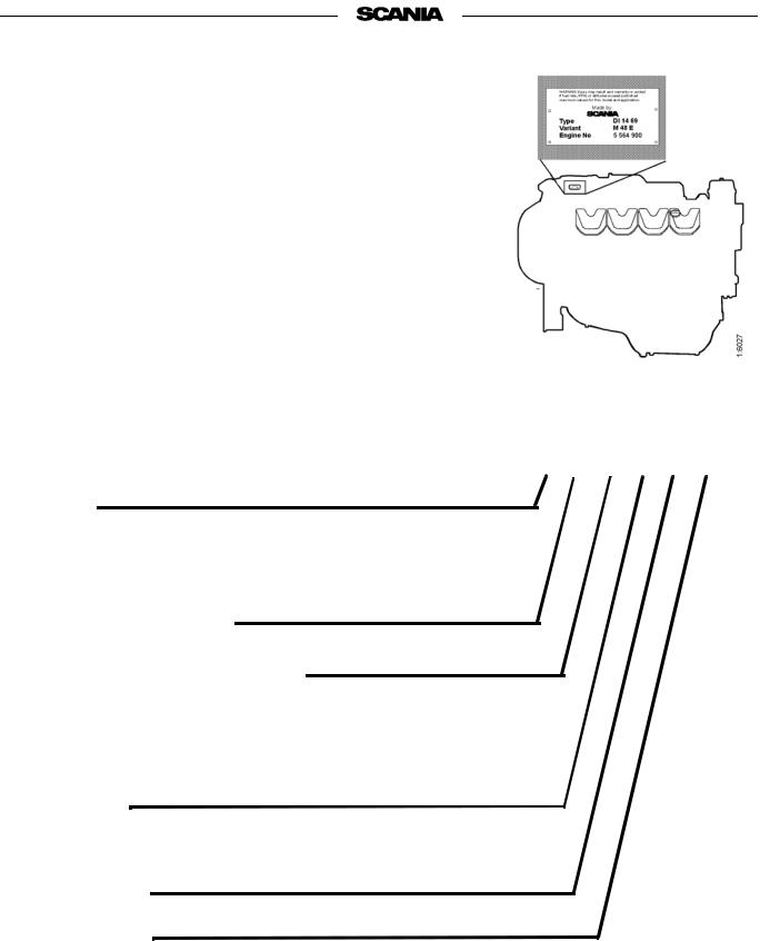
TYPE DESIGNATIONS
The engine designation indicates, in the form of a code, the type of engine, its size and intended use, etc.
The type designation and engine serial number are indicated on a type plate affixed to the right-hand side of the engine. The serial number is also punched in the engine block, adjacent to the first cylinder head. Refer to the illustration.
Engines that are certified regarding smoke and emissions are fitted with a certification plate specifying the documents they conform to. The plate is fitted to rocker cover number four from the front on the right hand side.
DI 14 69 M 48 E
Type
DI |
Supercharged diesel engine with liquid-cooled charge air cooler |
Swept volume in whole dm3
Performance and certification code
Indicates, together with the application code, the normal gross engine output.
The actual output setting of the engine is indicated on the engine card.
Application
M For marine use
Variant 01-99
Type of governor
E Electronically controlled governor (DEC2)
10 |
© Scania Industrial & Marine Engines |
2001-05:1 |

22 |
5 |
3 |
10 |
25 |
1 |
6 |
12 |
19 |
23 22 |
|
|
|
26 |
|
|
|
|
|
|
 2
2
16 |
21 |
|
20 |
22 |
|
22 |
8 |
10 |
13 |
7 |
4 |
|
11 |
||||||
|
|
|
||||
10 |
26 |
|
|
|
||
25 |
|
9 |
25 |
9
 9
9
|
|
|
24 |
|
|
|
|
|
|
15 |
|
14 |
|
|
17 |
18 |
|
|
|
|
|
|||||
|
The illustrations show a typical DI14 69 engine configuration. |
|
||||||
|
Your engine may have different equipment from the one shown. |
|
||||||
1. |
Type plate |
10. |
Turbocharger |
20. |
Seawater pump |
|
||
2. |
Engine serial number, |
11. |
Injection pump |
21. |
Heat exchanger |
|
||
3. |
punched in engine block |
12. |
Fuel filter |
22. |
Sacrificial anodes |
|||
Oil cooler |
13. |
Starter motor |
23. |
Expansion tank with pres- |
||||
4. |
Oil dipstick |
14. |
Alternator |
|
sure cap |
|
||
5. |
Oil cleaner |
15. |
Fan belt, adjuster |
24. |
Oil pressure monitor |
|||
6. |
Oil filter, turbo |
16. |
Coolant pipes to turbo |
25. |
Charge air cooler (seawa- |
|||
7. |
Drain plug, engine oil |
17. |
Inspection holes, engine |
|
ter-cooled) |
|
||
26. |
Seawater pipe to charge air |
|||||||
8. |
Coolant pump |
|
block |
|||||
9. |
Charge air cooler (engine |
18. |
Drain cock, coolant |
|
cooler |
|
||
|
|
|
|
|||||
|
coolant-cooled) |
19. |
Oil filler cap |
|
|
|
|
|
2001-05:1 |
© Scania Industrial & Marine Engines |
11 |

DEC2 CONTROL SYSTEM
This engine has an injection pump with an electromagnetic actuator which adjusts the control rack to give the correct amount of fuel.
The system which controls the pump is called DEC2 (Digital Engine Control, generation 2).
The control unit (DEC2) continuously receives signals from sensors for engine speed, charge air temperature and pressure, coolant temperature, oil pressure, throttle position and control rack travel in the injection pump. Using this input data and a control program, the correct amount of fuel for the current operating conditions can be calculated.
The system’s sensors may be used only for DEC2, not for other instruments or other monitoring purposes.
The control unit contains monitoring functions to protect the engine in the event of a fault which would otherwise damage it. Faults and the more important monitoring functions are indicated on the control unit in the form of light emitting diodes. See illustration on page 14 for a description.
In case of a fault, the Power - or Shutdown indicator on the DEC2 control unit as well as the main indicator lamp on the main supply box and the instrument panel will illuminate.
If a fault has been indicated on the main indicator lamp the operator can determine the cause of the fault with the help of the LEDs on the control unit and the troubleshooting schedule on page 17, and carry out the required investigation and remedy.
Depending on the nature of the fault, the control system will take different actions to protect the engine such as reducing the power output, keeping the engine running at a constant low speed or, in case of a function impairing fault, shutting down the engine (Shutdown).
To enable readout of LED fault codes there is a lamp test/fault code switch located in the main supply box near the control unit.
A PC based program is also available to help service personnel to detect and rectify faults and to adjust certain parameters in the operating program.
Diagnostics and changes to programs must only be performed by authorized personnel.
The locations of the sensors and monitors that send signals to the control unit are shown in the illustrations on pages 13.
There is a description of the functions of the LEDs during normal operation on page 14.
On page 15 there is a description of the functions of the LEDs in case of a fault and actions in case of Power- and Shutdown indication.
Troubleshooting and fault code reading are described on pages 16 and 17.
12 |
© Scania Industrial & Marine Engines |
2001-05:1 |

Location of sensors for DEC2
2
1
6
3 |
|
4 |
|
|
|
1.Connection of lead to charge air temperature sensor
2.Charge air temperature sensor
3.Coolant temperature sensor
4.Engine speed sensors
5.Oil pressure monitor
6.Connector panel
2001-05:1 |
© Scania Industrial & Marine Engines |
13 |

LED functions during normal operation
Note: The lamp test/fault code switch should not be depressed. All LEDs come on briefly when the control unit is powered up.
CONTROL STATUS
The LED flashes continuously when the control unit is supplied with current, regardless of whether the engine is running or not.
SHUTDOWN
The LED is out.
STARTING
The LED lights up as soon as the engine turns over on cranking and follows the programmed starting sequence until it has been completed and then goes out.
RUNNING
The LED comes on when the engine has started and the "Starting" LED goes out. It remains on until the engine is stopped.
TORQUE LIMIT
The LED comes on when the control unit detects that the engine has received the maximum permissible quantity of injected fuel according to its power curve. This means 100% power output at the current rpm. If the load increases, engine rpm will decrease.
BOOST LIMIT
The LED comes on when the control unit smoke limiter restricts the maximum fuel quantity. Operation of the smoke limiter is dependent on the charge air pressure.
POWER-
The LED remains out during normal operation as long as no fault is detected by the control unit. See next page for the procedure to be adopted in the event of a fault.
POWER+
If the control unit is programmed to allow the engine to be operated according to more than one power/torque curve (map), the following applies.
The LED comes on when the engine is run at more than 100% power output (MAP 2). It goes out when the engine returns to the 100% power output curve (MAP 1) or when the power output required is less than 100%.
14 |
© Scania Industrial & Marine Engines |
2001-05:1 |

Action in case of a fault
LED indications in case of a fault
Note The main indicator lamp in the main supply box and at the instrument panel has indicated a fault. The lamp test/fault code switch should not be depressed.
CONTROL STATUS
The LED will continue to flash even in case of a fault as long as voltage is supplied to the control unit.
POWER -
If the LED comes on, the control unit has detected a defect that could cause damage to the engine if operation continues.
The control unit automatically reduces engine power output to a predefined level if the corresponding function has been selected.
Action: Reduce engine speed to idle if possible and conduct troubleshooting according to instructions on page 16 and the chart on page 17
SHUTDOWN
The LED comes on and the engine is switched off automatically in case of a severe fault that could cause damage to the engine if operation continues.
Action: Conduct troubleshooting according to instructions on page 16 and the chart on page 17
If the engine has not stopped, reduce engine speed to idle and conduct troubleshooting.
2001-05:1 |
© Scania Industrial & Marine Engines |
15 |
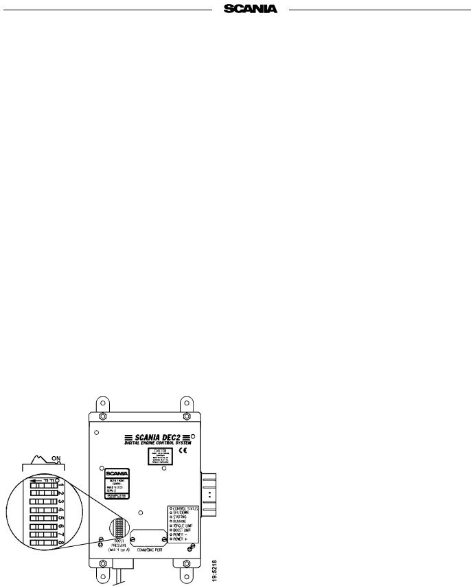
Changing functions using the DIP switches in the control unit
There are 8 DIP switches in the control unit under the round black rubber cover.
These switches shall be in the ON position to obtain normal functions according to the operating program. However, for single-speed engines, the normal position of DIP switches 6, 7, and 8 may also be OFF
Shutdown at threshold values for low oil pressure and high coolant temperature can be selected by setting DIP switch 4 to OFF
With DIP switch 4 in position ON, Power- indication is obtained for these threshold values. Engine output reduction (LOP) can be selected to prevent damage to the engine. Changes to the program must only be performed by authorized personnel.
Note Do not operate the engine with a Power- indication except for in emergencies.
The DIP switches are showed in ON position
Readout of fault codes
Note If the engine has stopped or lost power but the main indicator lamp is out and neither POWERnor SHUTDOWN are on, the fault is outside the control unit detection range. Probable causes: fuel shortage, temporary overload, mechanical fault.
-Activate the lamp test/fault code switch. In Scania electrical equipment the main indicator lamp is located in this switch on the main supply box.
-All LEDs will then come on for 2 seconds to indicate that they are intact and in working order. This also applies to the main indicator lamp in the main supply box and the instrument panel. Make a note of any LED that is defective.
-All LEDs will then be out for approximately 4 seconds.
-Following this, a fault code will be indicated on one of the LEDs for 2 seconds. Note which LED it is.
-The control unit then resumes the operating mode automatically.
-After having made a note of the fault code, reset the lamp test/fault code switch and reset the control unit by turning off its power supply momentarily.
-The most probable cause of the fault can then be found in the trouble shooting schedule on the next page.
-When the fault or faults have been rectified the engine can be restarted.
-If the control system continues to indicate a fault by way of the main indicator lamp, further faults may have been recorded. The fault code readout must then be repeated as per above since the system can only display one fault code at a time.
-The fault(s) will be stored in a special memory in the control unit along with information about the operating time when it(they) occurred. Stored faults can be accessed and erased by authorised service personnel.
16 |
© Scania Industrial & Marine Engines |
2001-05:1 |

-2001 |
|
|
|
|
|
|
|
|
|
|
|
|
|
|
|
|
|
|
|
|
READOUT OF FAULT CODES |
|
|
|
|
|
|
|
|
|
|
|
|
|
|
05:1 |
|
|
|
|
|
LED INDICATION WHEN THE LAMP TEST/FAULT CODE SWITCH IS ACTIVATED |
|||||
|
|
|
|
|
|
|
|
|
|
|
|
|
CONTROLSTATUS |
SHUTDOWN |
STARTING |
RUNNING |
TORQUELIMIT |
|
LIMITBOOST |
-POWER |
+POWER |
Probable cause |
Action |
|
|
|
|
|
|
|
|
|
|
||
|
|
|
|
|
|
|
|
|
|
|
|
© |
|
|
|
|
|
|
|
|
|
DEC2 has detected an internal fault in the control unit. |
Send in the control unit for repair as soon as |
Scania |
|
|
|
|
|
|
|
|
|
|
possible. |
|
|
|
|
|
|
|
|
|
|
|
|
|
|
|
|
|
|
|
|
|
The engine temperature has reached the threshold level |
Check the cooling system. Check the temperature |
|
&Industrial |
|
|
|
|
|
|
|
|
|
or the temperature sensor is inoperative. |
sensor and cable routing. |
|
|
|
|
|
|
|
|
|
|
|
|
|
|
|
|
|
|
|
|
|
The engine has reached the overrevving limit or the |
Check the wiring and connector. |
|
|
|
|
|
|
|
|
|
|
|
engine speed sensor is inoperative. |
Renew the engine speed sensor. |
|
|
|
|
|
|
|
|
|
|
|
|
Marine |
|
|
|
|
|
|
|
|
|
Control rack position sensor inoperative. |
Check connectors and cables to governor. |
|
|
|
|
|
|
|
|
|
|
|
|
|
|
|
|
|
|
|
|
The intake air temperature has reached the threshold |
Check the intake system. Check the temperature |
||
Engines |
|
|
|
|
|
|
|
|
|
level or the charge air temperature sensor is inoperative. |
sensor and cable routing. |
|
|
|
|
|
|
|
|
|
|
|
|
|
|
|
|
|
|
|
|
|
The charge air pressure sensor is inoperative. |
control unit for repair if the connection is damaged. |
|
|
|
|
|
|
|
|
|
|
|
DEC2 detects no charge air pressure. |
Check the charge air pressure hose. Send in the |
|
|
|
|
|
|
|
|
|
|
|
|
|
|
|
|
|
|
|
|
|
|
Engine speed potentiometer or the idling safety switch |
Check the cable routing, connectors and cables. |
|
|
|
|
|
|
|
|
|
|
is inoperative. |
|
|
|
|
|
|
|
|
|
|
|
|
|
|
|
|
|
|
|
|
|
|
|
The oil pressure has dropped to the threshold level or |
Check oil level, connector and cable. |
|
|
|
|
|
|
|
|
|
|
the oil pressure monitor is inoperative. |
Renew the oil pressure monitor. |
|
|
|
|
|
|
|
|
|
|
|
|
=LED on
17
 Loading...