


UD46E-C

User Manual
UD46E-A UD46E-C UD46E-B UD55E-B
The color and the appearance may differ depending on the product, and the
specifications are subject to change without prior notice to improve the performance.

Table of contents
Before Using the Product
Copyright 5
Safety Precautions 6
Symbols 6
Cleaning 6
Storage 7
Electricity and Safety 7
Installation 8
Operation 10
Precautions when handling the panel 13
Preparations
Checking the Components 14
Components 14
Parts 15
External sensor KIT 15
Reverse Side 16
Remote Control 17
Connection Using an IR Stereo Cable
(sold separately)
Before Installing the Product (Installation
20
Guide)
Switching between portrait and landscape 20
Ventilation 20
Dimensions 21
Installing the Wall Mount 22
Preparing before installing Wall-Mount 22
19
Installing the Wall Mount 22
Wall Mount Kit Specifications (VESA) 23
Remote Control (RS232C) 24
Cable Connection 24
Connection 27
Control Codes 28
Connecting and Using a Source
Device
Before Connecting 37
Pre-connection Checkpoints 37
Connecting to a PC 37
Connection using the D-SUB cable
(Analog type)
Connection using a DVI cable (Digital type) 38
Connection Using an HDMI-DVI Cable 38
Connection Using an HDMI Cable 39
Connection Using an DP Cable 39
Connecting to a Video Device 40
Connection Using an HDMI-DVI Cable 40
Connection Using an HDMI Cable 41
Connecting to an Audio System 41
Connecting the LAN Cable 42
Connecting the Network box
(Sold separately)
MagicInfo 43
37
43
Changing the Input source 45
Source 45
Using MDC
MDC Program Installation/Uninstallation 46
Installation 46
Uninstallation 46
Connecting to MDC 47
Using MDC via RS-232C (serial data communications
standards)
Using MDC via Ethernet 48
47
Home feature
Video Wall 50
Video Wall 50
Horizontal x Vertical 50
Screen Position 51
Format 51
Picture Mode 52
On/Off Timer 53
On Timer 53
Off Timer 53
Holiday Management 54
Network Settings 55
MagicInfo Player I 56
2
Table of contents
ID Settings 57
ID Settings 57
Device ID Auto Set 57
PC Connection Cable 57
More settings 58
Screen Adjustment
Picture Mode 59
Backlight / Brightness / Contrast / Sharpness /
Color / Tint (G/R)
Color Temperature 60
White Balance 60
Gamma 60
Calibrated Value 60
Picture Options 61
Color Tone 61
HDMI Black Level 61
Dynamic Backlight 61
UHD COLOR 61
Picture Size 62
Picture Size 62
Zoom/Position 62
Resolution 62
Auto Adjustment 63
PC Screen Adjustment 63
60
Picture Off 63
Reset Picture 63
OnScreen Display
Display Orientation 64
Onscreen Menu Orientation 64
Source Content Orientation 64
Aspect Ratio 64
Screen Protection 65
Pixel Shift 65
Timer 65
Immediate Display 65
Side Gray 65
Message Display 66
Source Info 66
No Signal Message 66
MDC Message 66
Menu Language 66
Reset OnScreen Display 66
System
Setup 67
Time 68
Clock Set 68
DST 68
Sleep Timer 68
Power On Delay 68
MagicInfo I Source 68
Auto Source Switching 68
Auto Source Switching 68
Primary Source Recovery 68
Primary Source 69
Secondary Source 69
Power Control 69
Auto Power On 69
PC Module Power 69
Standby Control 69
Network Standby 69
Power Button 69
Eco Solution 70
Energy Saving 70
Eco Sensor 70
Screen Lamp Schedule 70
No Signal Power Off 70
Auto Power Off 70
Temperature Control 70
Change PIN 71
General 71
Security 71
HDMI Hot Plug 71
Reset System 71
3

Table of contents
Sound Adjustment
HDMI Sound 72
Sound on Video Call 72
Reset Sound 72
Support
Software Update 73
Contact Samsung 73
Go to Home 74
Video Wall 74
Picture Mode 74
On/Off Timer 74
Network Settings 74
MagicInfo Player I 74
ID Settings 74
More settings 74
Reset All 74
Q & A 83
Specifications
General 85
PowerSaver 87
Preset Timing Modes 88
Appendix
Responsibility for the Pay Service
(Cost to Customers)
Not a product defect 91
A Product damage caused by customer's fault 91
Others 91
Optimum Picture Quality and Afterimage Burnin Prevention
Optimum Picture Quality 92
Prevention of Afterimage Burn-in 92
91
92
Troubleshooting Guide
Requirements Before Contacting Samsung
Customer Service Center
Testing the Product 75
Checking the Resolution and Frequency 75
Check the followings. 76
75
License 94
Terminology 95
4

Chapter 01
Before Using the Product
Copyright
The contents of this manual are subject to change without notice to improve quality.
© 2015 Samsung Electronics
Samsung Electronics owns the copyright for this manual.
Use or reproduction of this manual in parts or entirety without the authorization of Samsung Electronics is prohibited.
Microsoft, Windows are registered trademarks of Microsoft Corporation.
VESA, DPM and DDC are registered trademarks of the Video Electronics Standards Association.
Ownership of all other trademarks is attributed to their due owner.
5
Safety Precautions
Caution
RISK OF ELECTRIC SHOCK DO NOT OPEN
Caution : TO REDUCE THE RISK OF ELECTRIC SHOCK, DO NOT REMOVE COVER. (OR BACK)
THERE ARE NO USER SERVICEABLE PARTS INSIDE.
REFER ALL SERVICING TO QUALIFIED PERSONNEL.
This symbol indicates that high voltage is present inside.
It is dangerous to make any kind of contact with any internal part of this product.
This symbol alerts you that important literature concerning operation and maintenance has been
included with this product.
Symbols
Cleaning
―
Exercise care when cleaning as the panel and exterior of advanced LCDs are easily scratched.
―
Take the following steps when cleaning.
―
The following images are for reference only. Real-life situations may differ from what is shown in the
images.
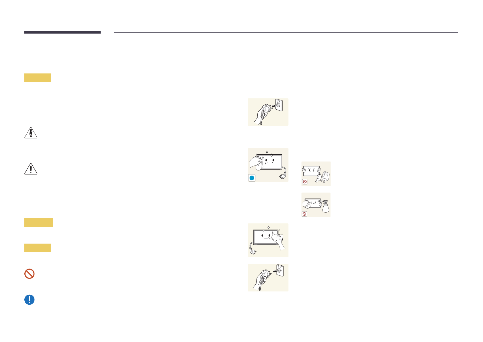
Power off the product and computer.
1
Disconnect the power cord from the product.
2
―
Hold the power cable by the plug and do not touch the cable with wet
hands. Otherwise, an electric shock may result.
Wipe the product with a clean, soft and dry cloth.
3
•
Do not use detergents that contain alcohol, solvent or
surface-active agents.
!
•
Do not spray water or detergent directly on the product.
Warning
A serious or fatal injury may result if instructions are not followed.
Caution
Personal injury or damage to properties may result if instructions are not followed.
Activities marked by this symbol are prohibited.
Instructions marked by this symbol must be followed.
Wet a soft and dry cloth in water and wring thoroughly to clean the
4
exterior of the product.
Connect the power cord to the product when cleaning is finished.
5
Power on the product and computer.
6
6
Storage
Due to the characteristics of high-glossy products, using a UV humidifier nearby may create
white-colored stains on the product.
―
Contact Customer Service Center if the inside of the product needs cleaning (service fee will be
charged).
Electricity and Safety
―
The following images are for reference only. Real-life situations may differ from what is shown in the
images.
Warning
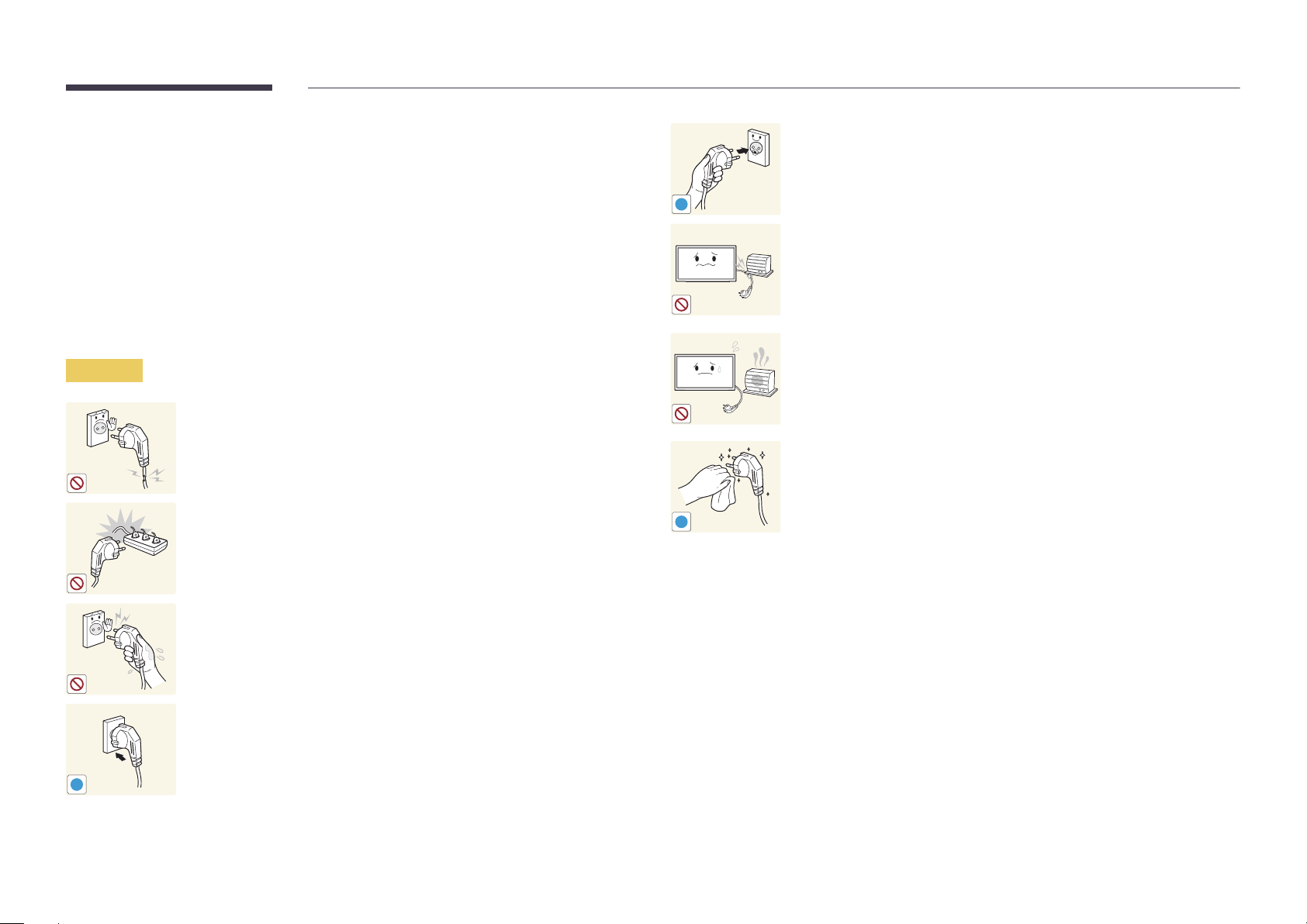
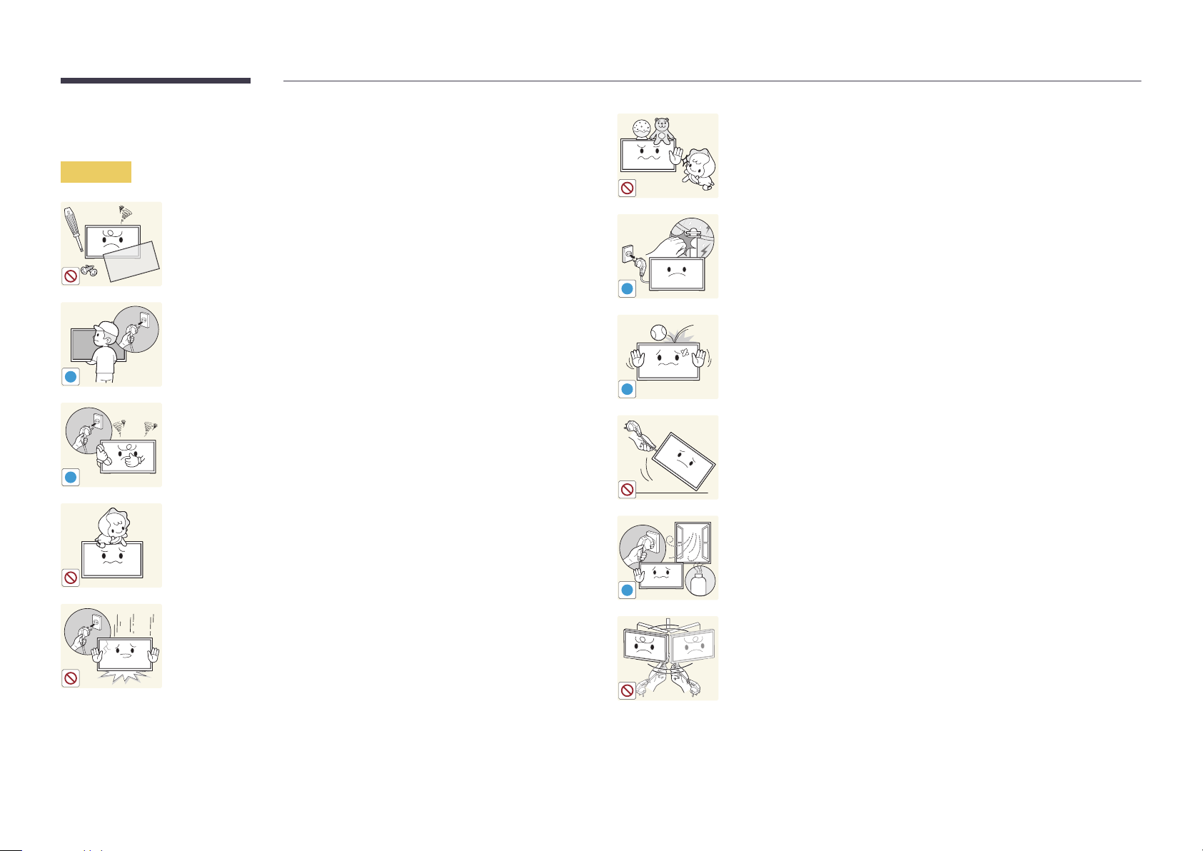
Do not use a damaged power cord or plug, or a loose power socket.
•
An electric shock or fire may result.
Do not use multiple products with a single power socket.
•
Overheated power sockets may cause a fire.
Connect the power plug to a grounded power socket
(type 1 insulated devices only).
•
An electric shock or injury may result.
!
Do not bend or pull the power cord with force. Be careful not to leave the
power cord under a heavy object.
•
Damage to the cord may result in a fire or electric shock.
Do not place the power cord or product near heat sources.
•
A fire or electric shock may result.
Clean any dust around the pins of the power plug or the power socket with
a dry cloth.
•
A fire may result.
!
Do not touch the power plug with wet hands. Otherwise, an electric shock
may result.
Insert the power plug all the way in so it is not loose.
•
An unsecure connection may cause a fire.
!
7
Caution
!
!
!
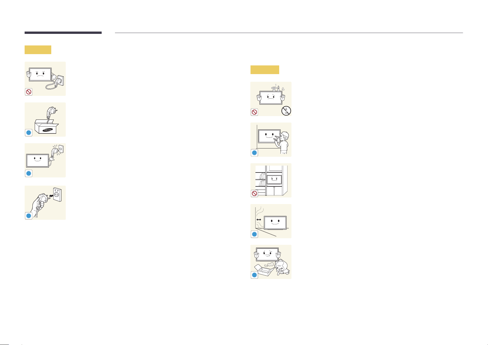
Do not disconnect the power cord while the product is being used.
•
The product may become damaged by an electric shock.
Only use the power cord provided with your product by Samsung. Do not
use the power cord with other products.
•
A fire or electric shock may result.
Keep the power socket where the power cord is connected unobstructed.
•
The power cord must be disconnected to cut off power to the product
when an issue occurs.
•
Note that the product is not completely powered down by using only
the power button on the remote.
Hold the plug when disconnecting the power cord from the power socket.
•
An electric shock or fire may result.
Installation
Warning
!
DO NOT PLACE CANDLES, INSECT REPELLANTS OR CIGARETTES ON TOP OF
THE PRODUCT. DO NOT INSTALL THE PRODUCT NEAR HEAT SOURCES.
•
A fire may result.
Have a technician install the wall-mount hanger.
•
Installation by an unqualified person can result in an injury.
•
Only use approved cabinets.
Do not install the product in poorly ventilated spaces such as a bookcase or
closet.
•
An increased internal temperature may cause a fire.
Install the product at least 10 cm away from the wall to allow ventilation.
•
An increased internal temperature may cause a fire.
!
Keep the plastic packaging out of the reach of children.
•
Children may suffocate.
!
8
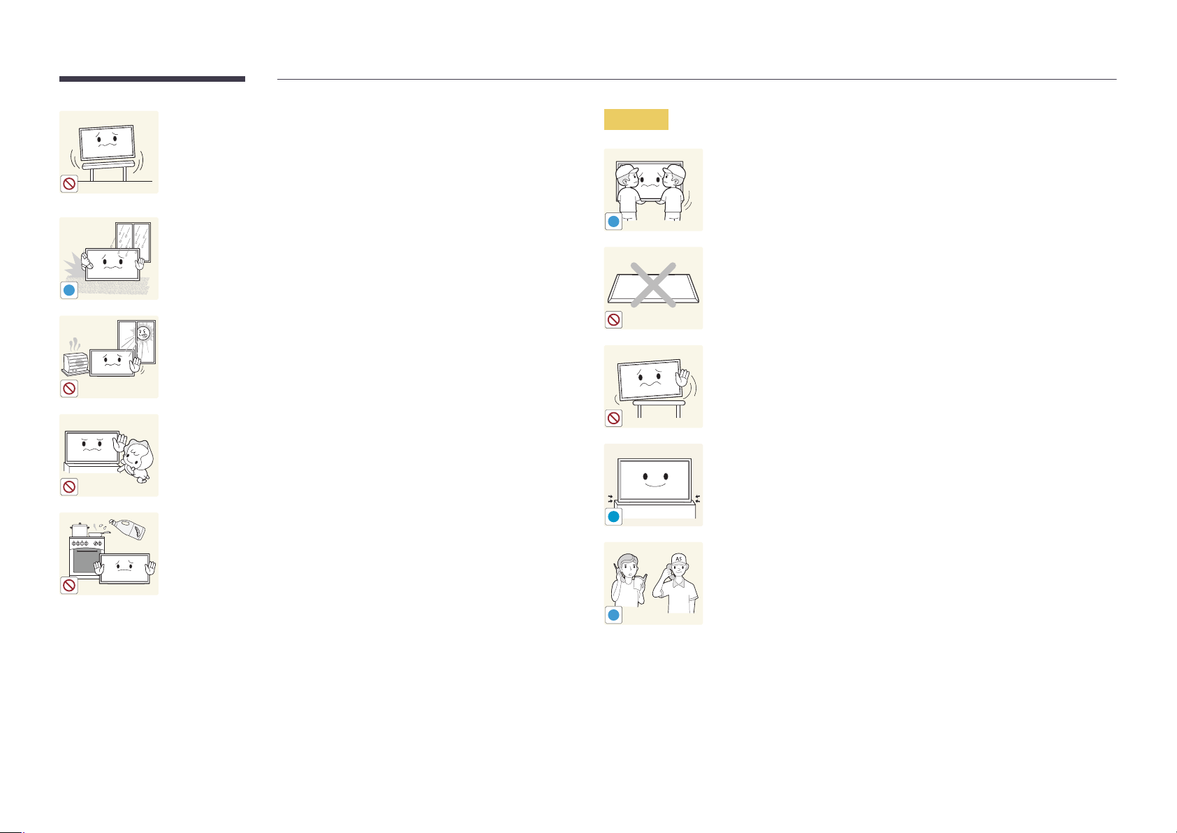
Do not install the product on an unstable or vibrating surface (insecure shelf,
sloped surface, etc.)
•
The product may fall and become damaged and/or cause an injury.
•
Using the product in an area with excess vibration may damage the
product or cause a fire.
Caution
Do not drop the product while moving.
•
Product failure or personal injury may result.
Do not install the product in a vehicle or a place exposed to dust, moisture
!
(water drips, etc.), oil, or smoke.
•
A fire or electric shock may result.
!
Do not set down the product on its front.
•
The screen may become damaged.
Do not expose the product to direct sunlight, heat, or a hot object such as a
stove.
•
The product lifespan may be reduced or a fire may result.
Do not install the product within the reach of young children.
•
The product may fall and injure children.
•
As the front is heavy, install the product on a flat and stable surface.
Edible oil, such as soybean oil, can damage or deform the product. Do not
!
When installing the product on a cabinet or shelf, make sure that the
bottom edge of the front of the product is not protruding.
•
The product may fall and become damaged and/or cause an injury.
•
Install the product only on cabinets or shelves of the right size.
Set down the product gently.
•
Product failure or personal injury may result.
install the product in a kitchen or near a kitchen counter.
Installing the product in an unusual place (a place exposed to a lot of fine
dust, chemical substances, extreme temperatures or a significant presence
of moisture, or a place where the product will operate continuously for an
SAMSUNG
!
extended period of time) may seriously affect its performance.
•
Be sure to consult Samsung Customer Service Center if you want to
install the product at such a place.
9
Operation
Warning
Do not leave heavy objects or items that children like (toys, sweets, etc.) on
top of the product.
•
The product or heavy objects may fall as children try to reach for the
toys or sweets resulting in a serious injury.
There is a high voltage inside the product. Never disassemble, repair or
modify the product yourself.
•
A fire or electric shock may result.
•
Contact Samsung Customer Service Center for repairs.
!
Before moving the product, turn off the power switch and disconnect the
power cable and all other connected cables.
•
Otherwise, the power cord may be damaged and a fire or electric
!
!
shock may result.
If the product generates abnormal sounds, a burning smell or smoke,
disconnect the power cord immediately and contact Samsung Customer
Service Center.
•
An electric shock or fire may result.
Do not let children hang from the product or climb on top of it.
•
Children may become injured or seriously harmed.
If the product is dropped or the outer case is damaged, turn off the power
switch and disconnect the power cord. Then contact Samsung Customer
Service Center.
•
Continued use can result in a fire or electric shock.
!
!
GAS
During a lightning or thunderstorm, power off the product and remove the
power cable.
•
A fire or electric shock may result.
Do not drop objects on the product or apply impact.
•
A fire or electric shock may result.
Do not move the product by pulling the power cord or any cable.
•
Product failure, an electric shock or fire may result from a damaged
cable.
If a gas leakage is found, do not touch the product or power plug. Also,
ventilate the area immediately.
•
Sparks can cause an explosion or fire.
Do not lift or move the product by pulling the power cord or any cable.
•
Product failure, an electric shock or fire may result from a damaged
cable.
10
Do not use or keep combustible spray or an inflammable substance near
the product.
•
An explosion or fire may result.
!
Ensure the vents are not blocked by tablecloths or curtains.
•
An increased internal temperature may cause a fire.
100
Do not insert metallic objects (chopsticks, coins, hairpins, etc) or objects
that burn easily (paper, matches, etc) into the product (via the vent or input/
output ports, etc).
•
Be sure to power off the product and disconnect the power cord
when water or other foreign substances have entered the product.
Then contact Samsung Customer Service Center.
•
Product failure, an electric shock or fire may result.
Caution
!
-_-
!
!
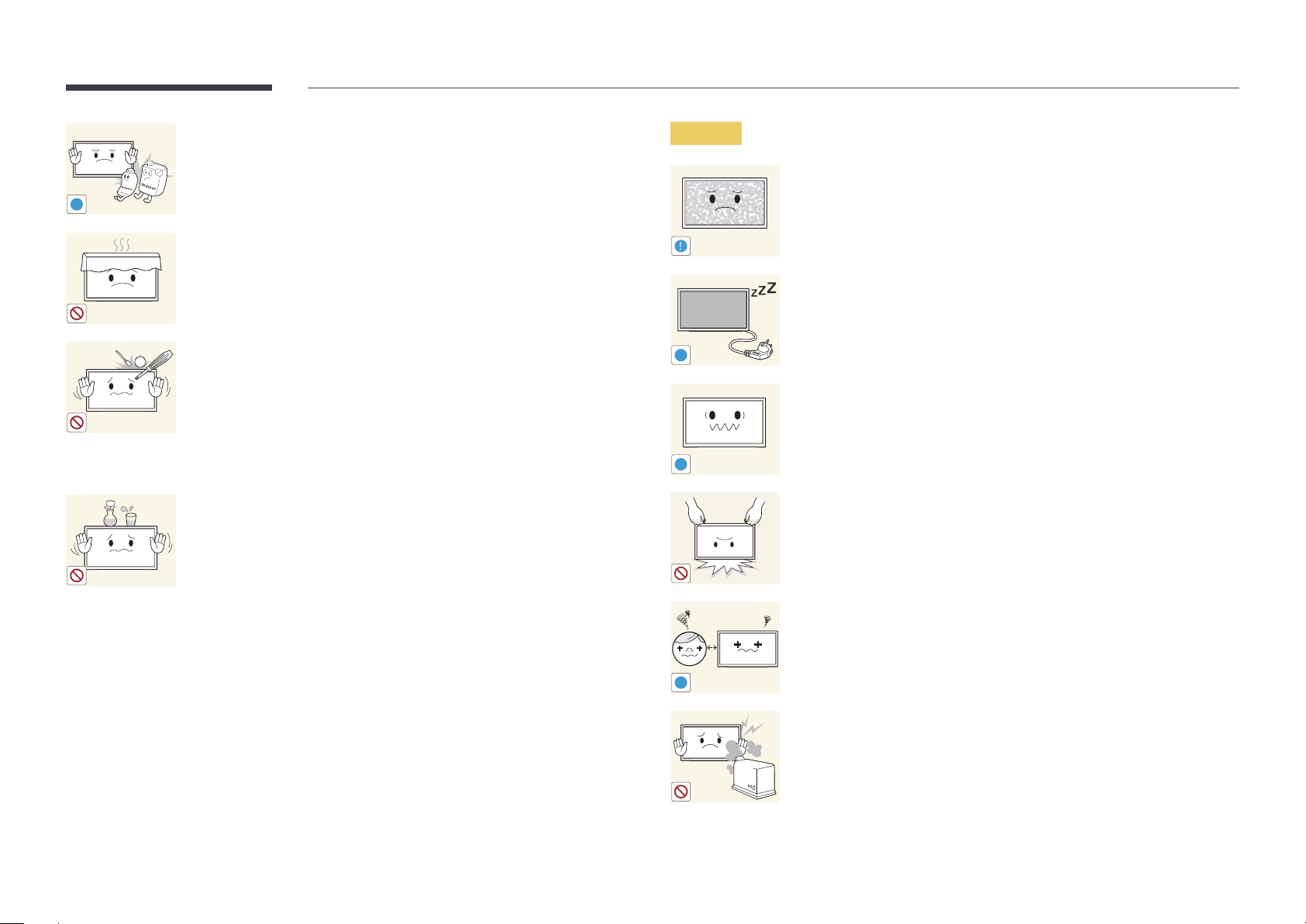
Leaving the screen fixed on a stationary image for an extended period of
time may cause afterimage burn-in or defective pixels.
•
Activate power-saving mode or a moving-picture screen saver if you
will not be using the product for an extended period of time.
Disconnect the power cord from the power socket if you do not plan on
using the product for an extended period of time (vacation, etc).
•
Dust accumulation combined with heat can cause a fire, electric shock
or electric leakage.
Use the product at the recommended resolution and frequency.
•
Your eyesight may deteriorate.
Do not place objects containing liquid (vases, pots, bottles, etc) or metallic
objects on top of the product.
•
Be sure to power off the product and disconnect the power cord
when water or other foreign substances have entered the product.
Then contact Samsung Customer Service Center.
•
Product failure, an electric shock or fire may result.
Do not hold the product upside-down or move it by holding the stand.
•
The product may fall and become damaged or cause an injury.
Looking at the screen too close for an extended period of time can
deteriorate your eyesight.
!
Do not use humidifiers or stoves around the product.
•
A fire or electric shock may result.
11
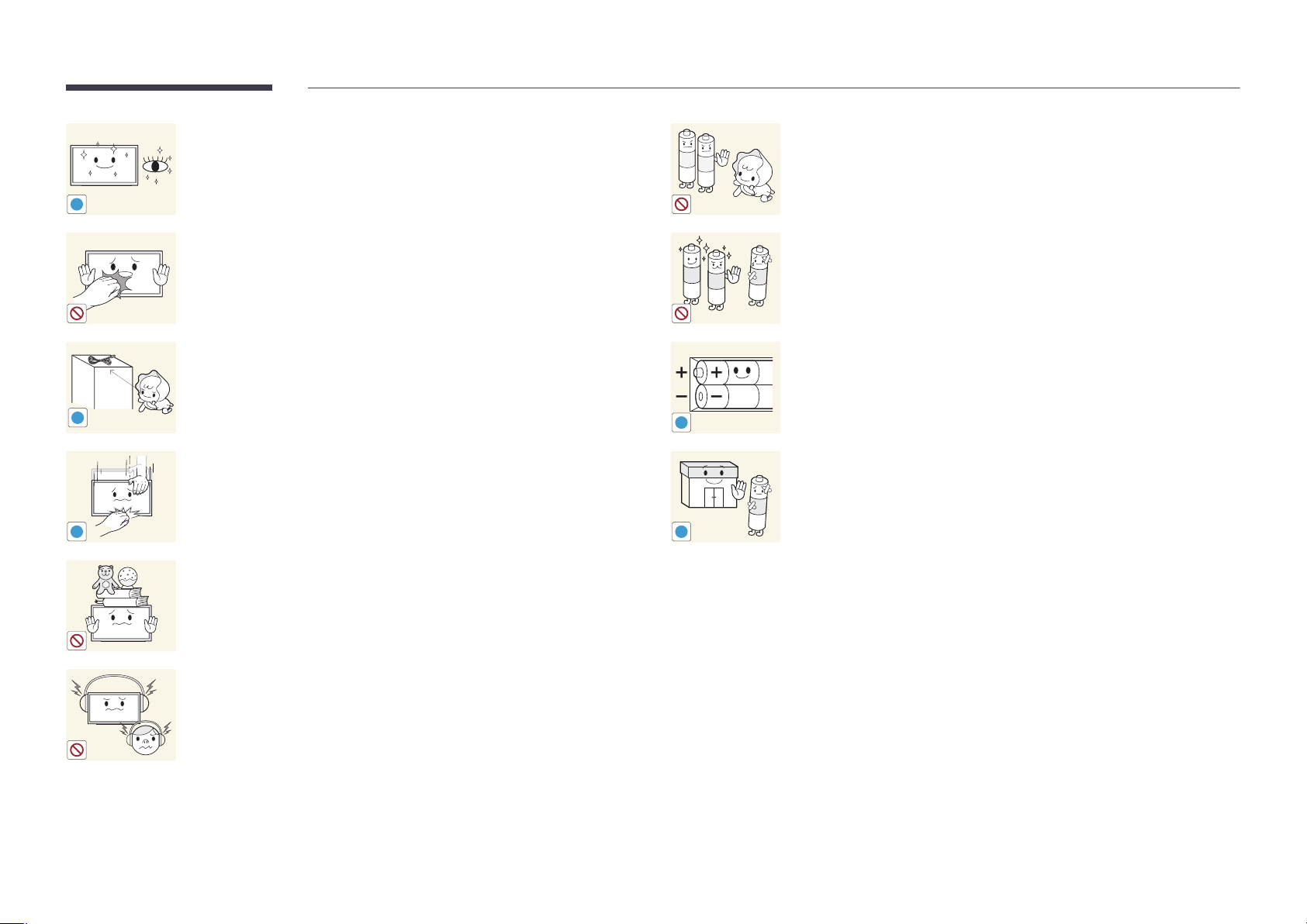
Rest your eyes for more than 5 minutes for every 1 hour of product use.
•
Eye fatigue will be relieved.
!
Be careful that children do not place the battery in their mouths when
removed from the remote control. Place the battery in a location that
children or infants cannot reach.
•
If children have had the battery in their mouths, consult your doctor
immediately.
Do not touch the screen when the product has been turned on for an
extended period of time as it will become hot.
Store small accessories out of the reach of children.
!
Exercise caution when adjusting the product angle or stand height.
•
Your hand or finger may get stuck and injured.
•
Tilting the product at an excessive angle may cause the product to fall
!
and an injury may result.
Do not place heavy objects on the product.
•
Product failure or personal injury may result.
When using headphones or earphones, do not turn the volume too high.
•
Having the sound too loud may damage your hearing.
!
!
When replacing the battery, insert it with the right polarity (+, -).
•
Otherwise, the battery may become damaged or it may cause fire,
personal injury or damage due to leakage of the internal liquid.
Use only the specified standardized batteries, and do not use a new battery
and a used battery at the same time.
•
Otherwise, the batteries may be damaged or cause fire, personal injury
or damage due to a leakage of the internal liquid.
The batteries (and rechargeable batteries) are not ordinary refuse and must
be returned for recycling purposes. The customer is responsible for returning
the used or rechargeable batteries for recycling.
•
The customer can return used or rechargeable batteries to a nearby
public recycling center or to a store selling the same type of the
battery or rechargeable battery.
12
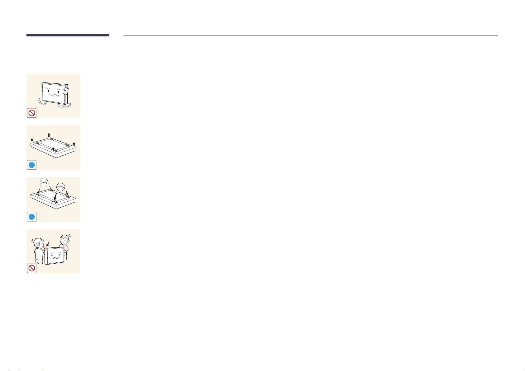
Precautions when handling the panel
Do not stand the product as shown in the image. The panel is fragile and
can get damaged.
Lay the product down to handle it as shown in the image. (the packaging
can be used).
!
Ensure you use the handles on the back when moving the product.
!
15 mm
Do not hold or grasp any area of the product within 15 mm from the front.
13
Chapter 02
Preparations
-
Contact the vendor where you
purchased the product if any
components are missing.
-
The pictures may look different from the
actual components.
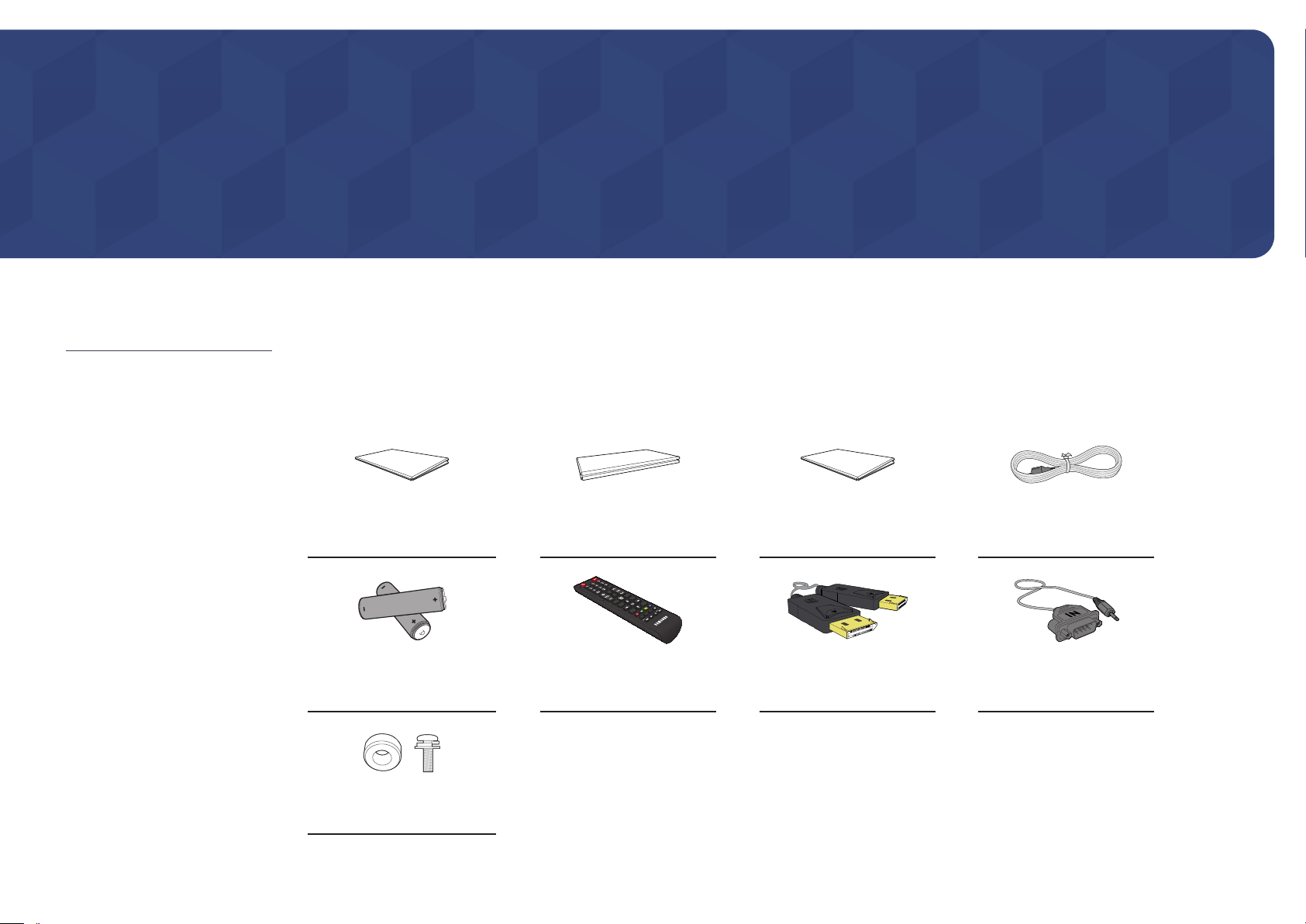
Checking the Components
Components
―
Components may differ in different locations.
Quick Setup Guide
-
-
Batteries
(Not available in some locations)
Holder-Ring (4EA) / Screw (4EA)
+
+
Warranty card
(Not available in some locations)
Remote Control DP cable RS232C(IN) adapter
Regulatory guide Power cord
14
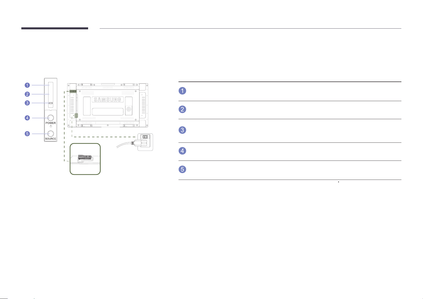
Parts
―
The External sensor KIT has a remote-control sensor, a brightness sensor and function keys. If mounting the display onto a
wall, you can move the External sensor KIT to the side of the display.
―
The color and shape of parts may differ from what is shown. Specifications are subject to change without notice to improve
quality.
External sensor KIT
POWER
Buttons Description
Remote Control
Sensor
Light sensor
ON
Use the remote control within 7m to 10m from the sensor on the product at an angle of 30
―
Store used batteries out of reach of children and recycle.
―
Do not use a new and used battery together. Replace both batteries at the same time.
―
Remove batteries when the remote control is not to be used for an extended period of time.
Power indicator
POWER button
SOURCE button
Aim the remote control towards this spot on the LCD Display.
―
Keep the area between the remote sensor and remote control obstacle-free.
Automatically detects the intensity of ambient light around a selected display and
adjusts the screen brightness.
The power indicator will turn off when the product is turned on. It will blink in
power-saving mode.
Use this button for turning the LCD Display on and off.
Switches from PC mode to Video mode.
Selects the input source that an external device is connected to.
from the left and right.
15
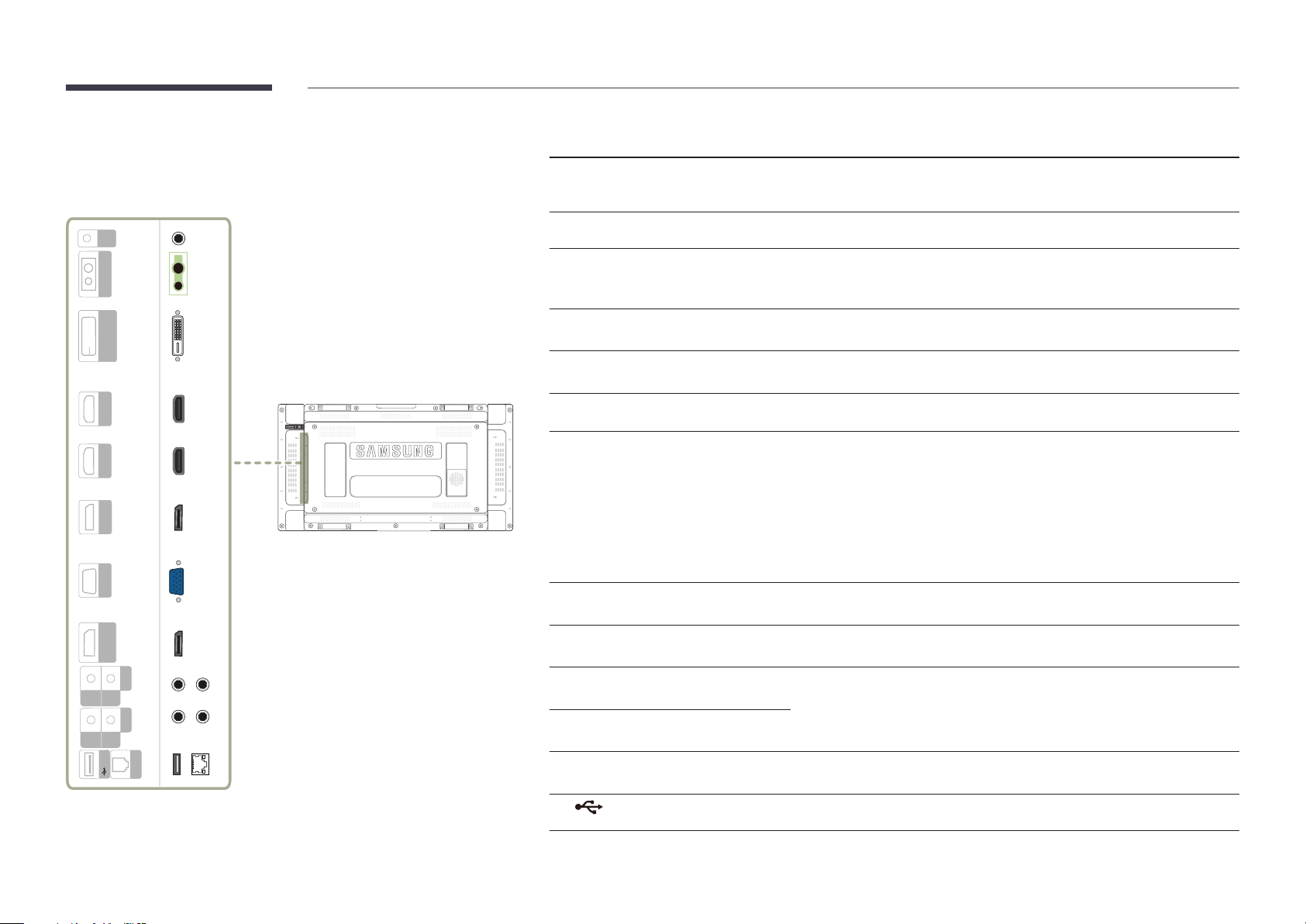
Reverse Side
Port Description
―
The color and shape of parts may differ from what is shown. Specifications are
subject to change without notice to improve quality.
OUT
IR
CONTROL IN
(MAGICINFO)
DVI IN
HDMI IN 1
HDMI IN 2
DP IN
RGB IN
(LOOPOUT)
DP OUT
AUDIO
OUT
IN
RS232C
OUT
IN
USB
RJ45
IR OUT
CONTROL IN
DVI IN (MAGICINFO)
HDMI IN 1, HDMI IN 2
DP IN
RGB IN
DP OUT (LOOPOUT)
AUDIO IN
AUDIO OUT
RS232C IN
RS232C OUT
RJ45
Receives the remote control signal via the external sensor board and outputs the
signal via LOOP OUT.
Supplies power to the external sensor board or receives the light sensor signal.
DVI IN: Connects to a source device using a DVI cable or HDMI-DVI cable.
MAGICINFO: To use MagicInfo, make sure to connect the DP-DVI cable.
Connects to a source device using an HDMI cable.
Connects to a PC using a DP cable.
Connects to a source device using a D-SUB cable.
Connects to another product using a DP cable.
―
When connecting monitors through DP Loopout, using the DP cable that
came with the package is recommended.
―
This port uses an algorithm that is specific to UHD resolution input and
output. The port is not compatible with monitors that have FHD contentspecific DP Loopout ports. Connecting Loopout ports between monitors
of the same model is recommended.
Receives sound from a PC via an audio cable.
Connects to the audio of a source device.
Connects to MDC using an RS232C adapter.
Connects to MDC using a LAN cable.
USB
Connect to a USB memory device. (Only for update purpose)
16
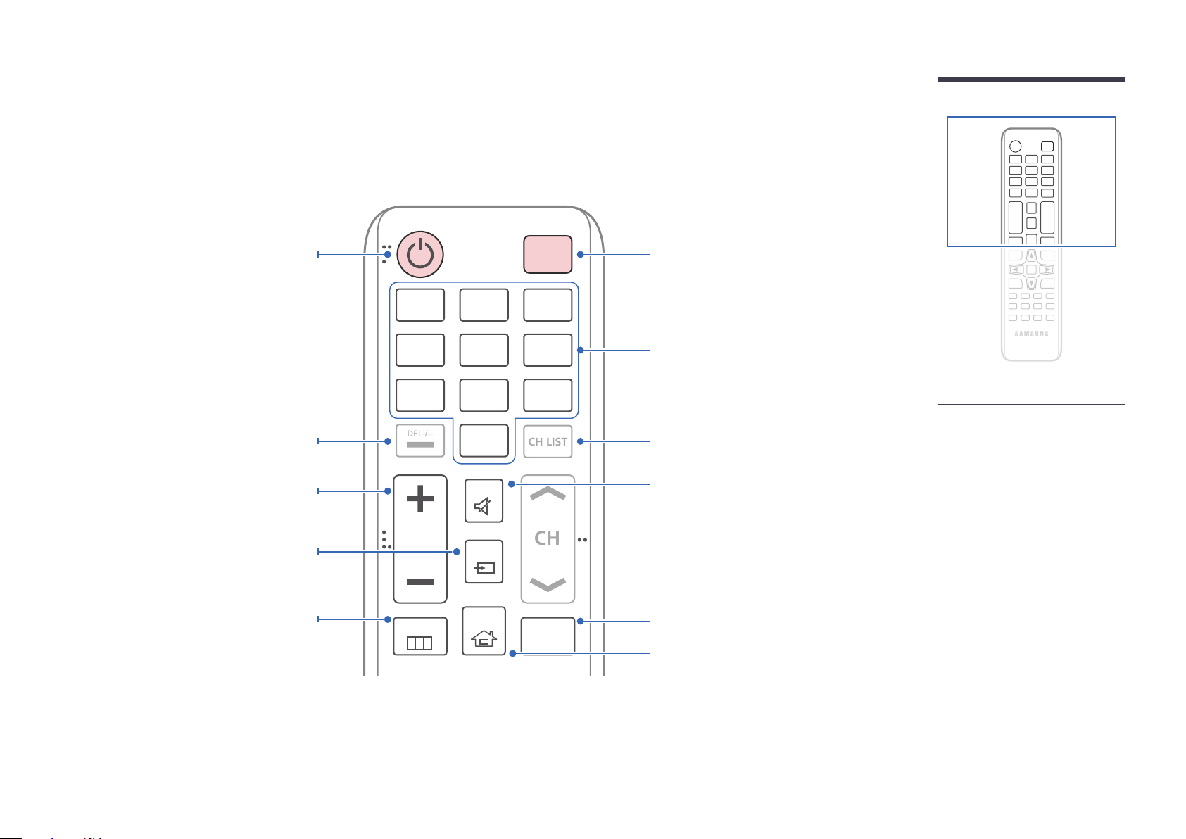
Remote Control
CH
DEL-/--
CH LIST
―
Using other display devices in the same space as the remote control of this product can cause the other display devices to be inadvertently controlled.
―
A button without a description in the image below is not supported on the product.
Power on the product.
Adjust the volume.
Change the input source.
Display or hide the onscreen display menu, or
return to the previous menu.
.QZ
1
GHI
4
PRS
7
VOL
MENU
ABC
2
JKL
5
TUV
8
SYMBOL
0
MUTE
SOURCE
HOME
POWER
OFF
DEF
3
MNO
6
WXY
9
MagicInfo
Player I
Power off the product.
Number buttons
Enter the password in the OSD menu.
Not Available.Not Available.
Mute the sound.
Unmuting the sound: Press MUTE again or press
the volume control(+ VOL -) button.
Use this hotkey to directly access MagicInfo Player I.
This hotkey is available when a network box or
PIM (Plug In Module) is connected.
Go to Home Launch Button.
-
Remote control button functions may
differ for different products.
17
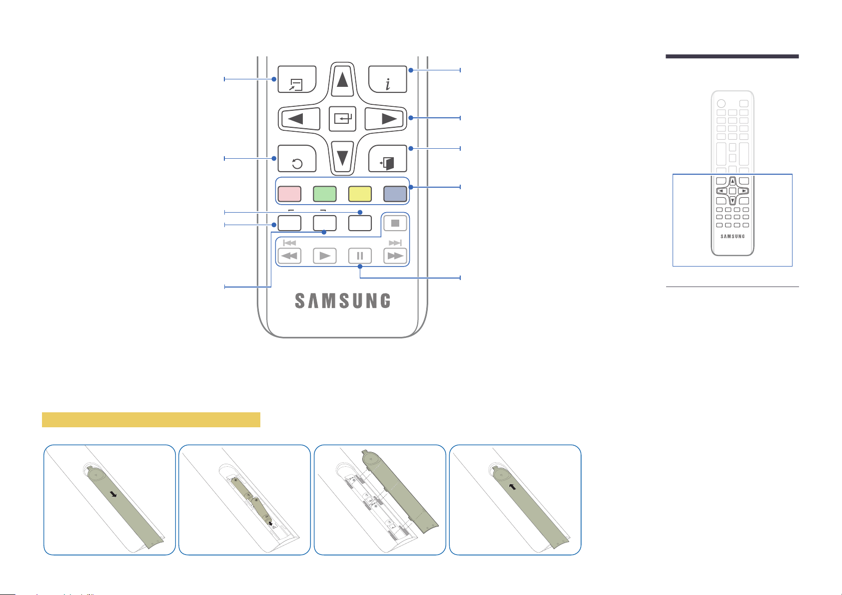
Quickly select frequently used functions.
TOOLS INFO
Display information about the current input
source.
Move to the upper, lower, left or right menu, or
adjust an option's setting.
Confirm a menu selection.
Return to the previous menu.
It sets safe lock function.
If multiple products are connected through the
Video Wall feature, press the SET button and
enter a product ID using the number buttons.
Control the product using the remote control.
Cancel a value that has been set using the
SET button and control all connected products
using the remote control.
To place batteries in the remote control
PC
A
SET
IR control
DVI
B
UNSET
HDMI
C
LOCK
EXITRETURN
DP
D
Exit the current menu.
Manually select a connected input source from
PC, DVI, HDMI, or DisplayPort.
Not Available.
-
Remote control button functions may
differ for different products.
18
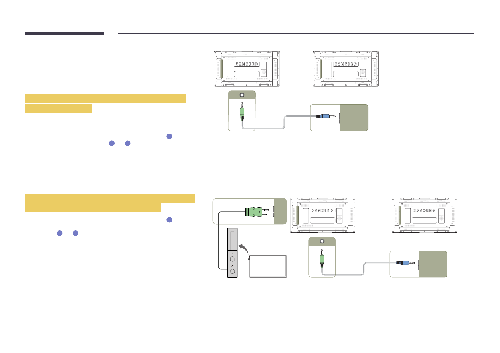
Connection Using an IR Stereo Cable
(sold separately)
Make sure to connect the External ambient sensor while the product is powered
off. Then, power on the product.
Controlling more than one display product using
your remote control
•
Connect the IR OUT port on the product to the IR /AMBIENT SENSOR IN
port on the other display product using the dedicated stereo cable.
•
A command sent from the remote control pointed at product
1
received by both display products
―
The appearance may differ depending on the product.
and 2.
1
will be
1 2
IR OUT IR /AMBIENT
SENSOR IN
Controlling more than one display product using an
External ambient sensor (sold separately)
•
A command sent from the remote control pointed at product
the External ambient sensor is connected) will be received by both display
products
―
The appearance may differ depending on the product.
1
and 2.
1
(to which
POWER
SOURCE
IR /AMBIENT
SENSOR IN
1 2
IR OUT IR /AMBIENT
SENSOR IN
19
Before Installing the Product
(Installation Guide)
To prevent injury, this apparatus must be securely attached to the floor/wall in accordance with the installation instructions.
•
Ensure that an authorized installation company installs the wall mount.
•
Otherwise, it may fall and cause personal injury.
•
Make sure to install the specified wall mount.
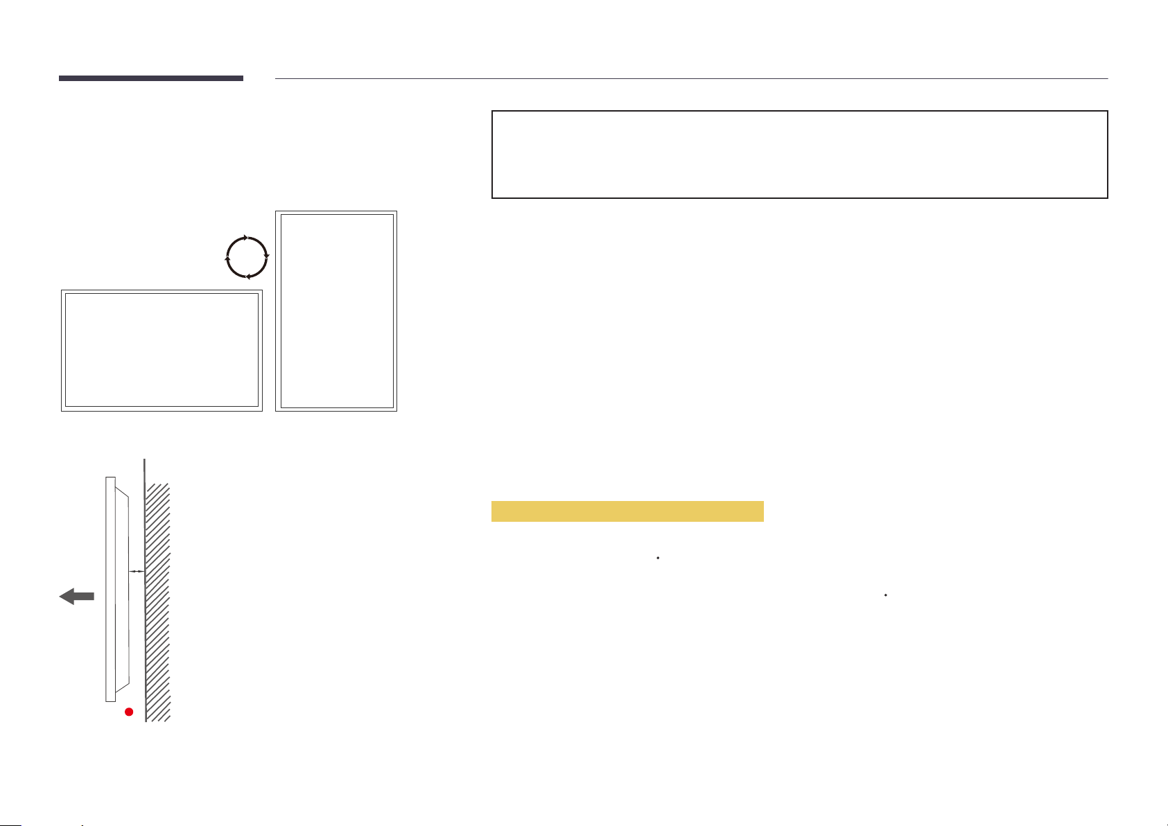
Switching between portrait and landscape
―
Contact Samsung Customer Service Center for further details.
•
To use the product in portrait orientation, rotate it clockwise.
Ventilation
Installation on a Perpendicular Wall
A
B
Figure 1.1 Side view
A Minimum 40 mm
B Ambient temperature: Under 35
•
When installing the product on a perpendicular wall, allow at least 40 mm of space between the product and wall surface
for ventilation and ensure that the ambient A temperature is kept below 35
C
C.
20
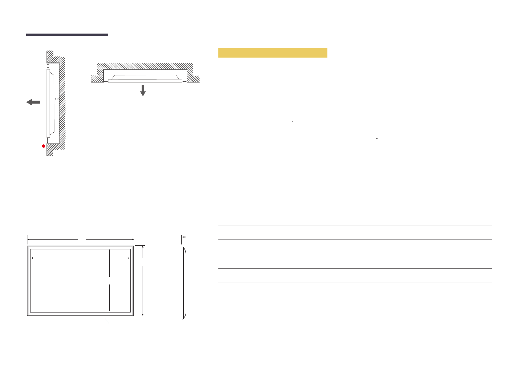
Figure 1.3 Side view
B
Installation on an Indented Wall
―
Contact Samsung Customer Service Center for further details.
A
C
E
Figure 1.2 Side view
Dimensions
1
D D
5
Plane view
A Minimum 40 mm
B Minimum 70 mm
C Minimum 50 mm
D Minimum 50 mm
E Ambient temperature: Under 35
―
When installing the product on an indented wall, allow at least the space specified above between the product and wall for
ventilation and ensure that the ambient temperature is kept below 35
Model name
UD46E-A 1022.1 (40.2) 1018.3 (40.1) 572.9 (22.6) 576.6 (22.7) 97.4 (3.8)
UD46E-C 1024 (40.3) 1018.3 (40.1) 572.9 (22.6) 578.6 (22.8) 113.6 (4.5)
1
C
C.
Unit: mm (inches)
2
3 4
5
2
3
4
UD46E-B 1022.1 (40.2) 1018.3 (40.1) 572.9 (22.6) 576.6 (22.7) 97.4 (3.8)
UD55E-B 1213.5 (47.8) 1209.8 (47.6) 680.6 (26.8) 684.3 (26.9) 96.6 (3.8)
―
All drawings are not necessarily to scale. Some dimensions are subject to change without prior notice. Refer to the
dimensions prior to performing installation of your product. Not responsible for typographical or printed errors.
21
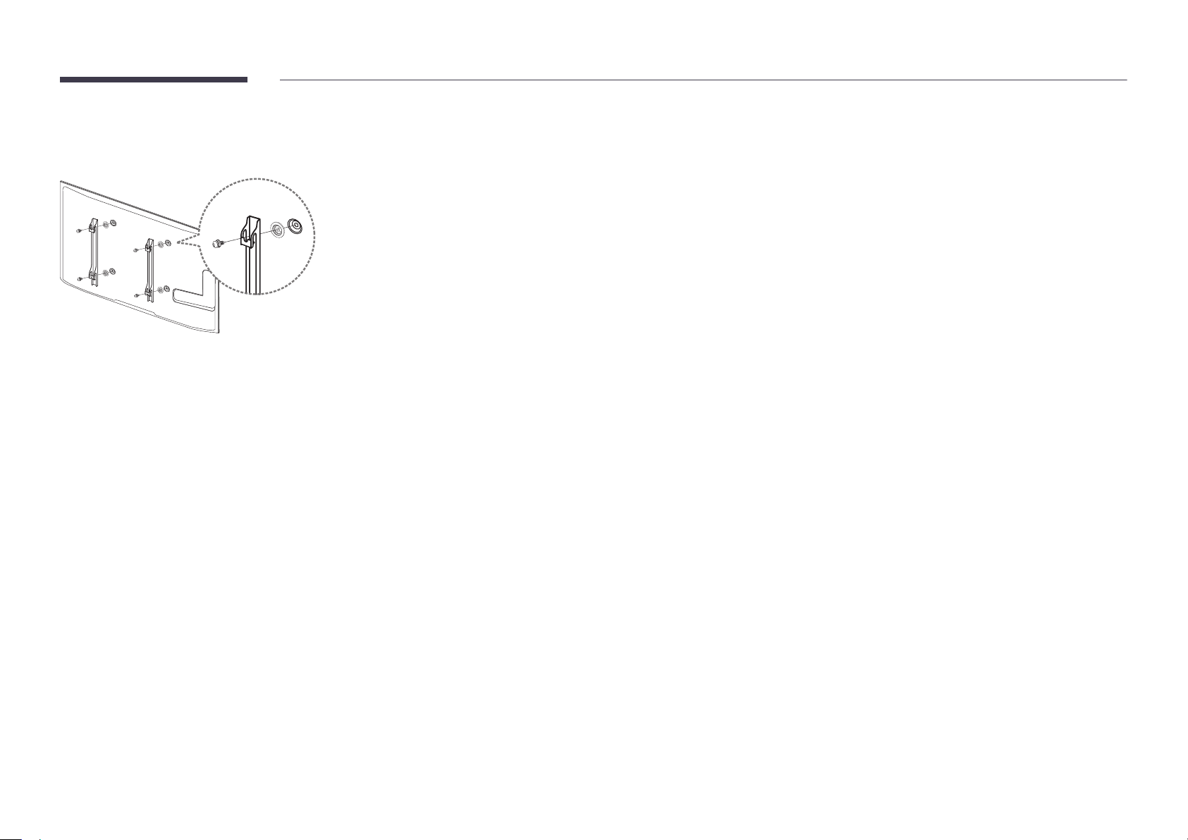
Installing the Wall Mount
1
Preparing before installing Wall-Mount
To install a wall-mount from another manufacturer, use the Holder-Ring(1).
Installing the Wall Mount
The wall mount kit (sold separately) allows you to mount the product on the wall.
For detailed information on installing the wall mount, see the instructions provided with the wall mount.
We recommend you contact a technician for assistance when installing the wall mount bracket.
Samsung Electronics is not responsible for any damage to the product or injury to yourself or others if you elect to install the
wall mount on your own.
22
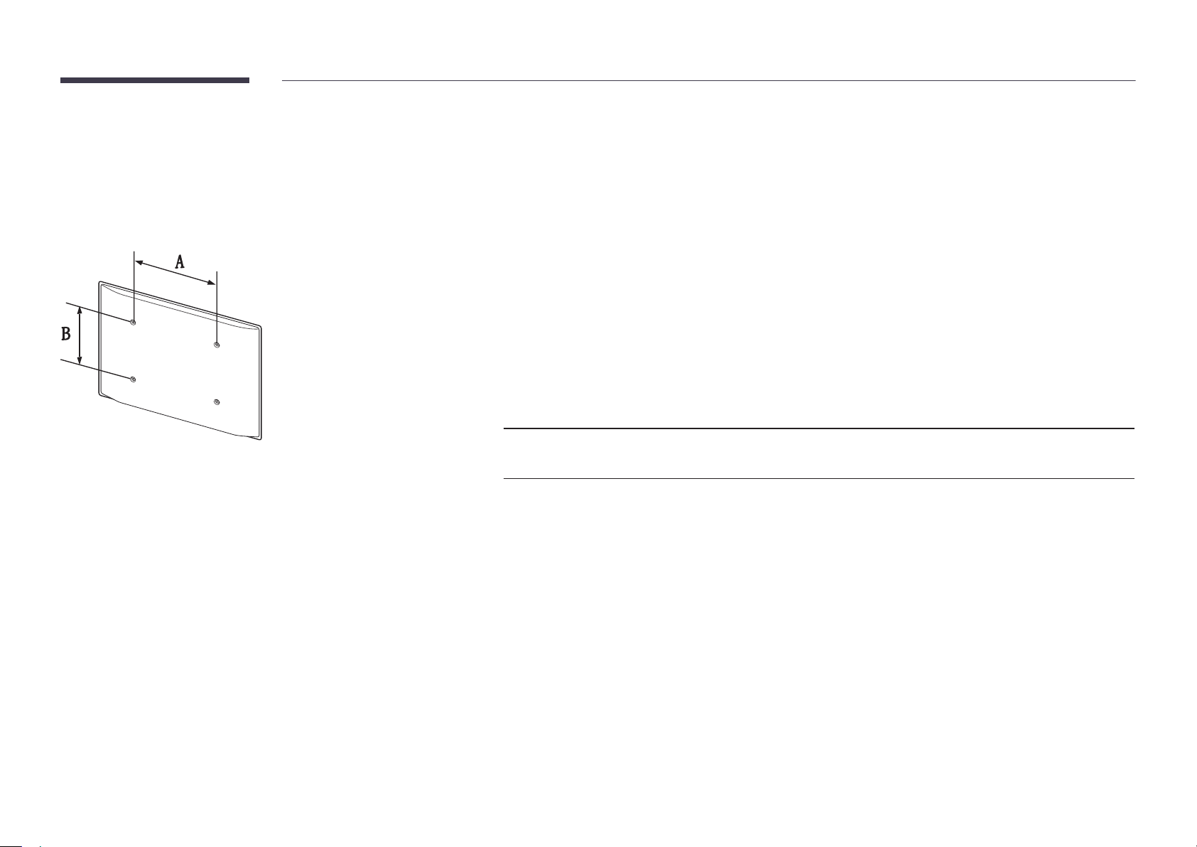
Wall Mount Kit Specications (VESA)
―
Install your wall mount on a solid wall perpendicular to the floor. Before
attaching the wall mount to surfaces other than plaster board, please contact
your nearest dealer for additional information.
If you install the product on a slanted wall, it may fall and result in severe
personal injury.
•
Samsung wall mount kits contain a detailed installation manual and all parts necessary for assembly are provided.
•
Do not use screws that are longer than the standard length or do not comply with the VESA standard screw
specifications. Screws that are too long may cause damage to the inside of the product.
•
For wall mounts that do not comply with the VESA standard screw specifications, the length of the screws may differ
depending on the wall mount specifications.
•
Do not fasten the screws too firmly. This may damage the product or cause the product to fall, leading to personal injury.
Samsung is not liable for these kinds of accidents.
•
Samsung is not liable for product damage or personal injury when a non-VESA or non-specified wall mount is used or the
consumer fails to follow the product installation instructions.
•
Always have two people mount the product on a wall.
•
Standard dimensions for wall mount kits are shown in the table below.
Unit: mm (inches)
Model name VESA screw hole
Standard Screw Quantity
specs (A * B) in
millimeters
UD46E-A / UD46E-C / UD46E-B
/ UD55E-B
―
Do not install your Wall Mount Kit while your product is turned on. It may result in personal injury due to electric shock.
600 x 400 (23.6 x 15.7) M8 4
23
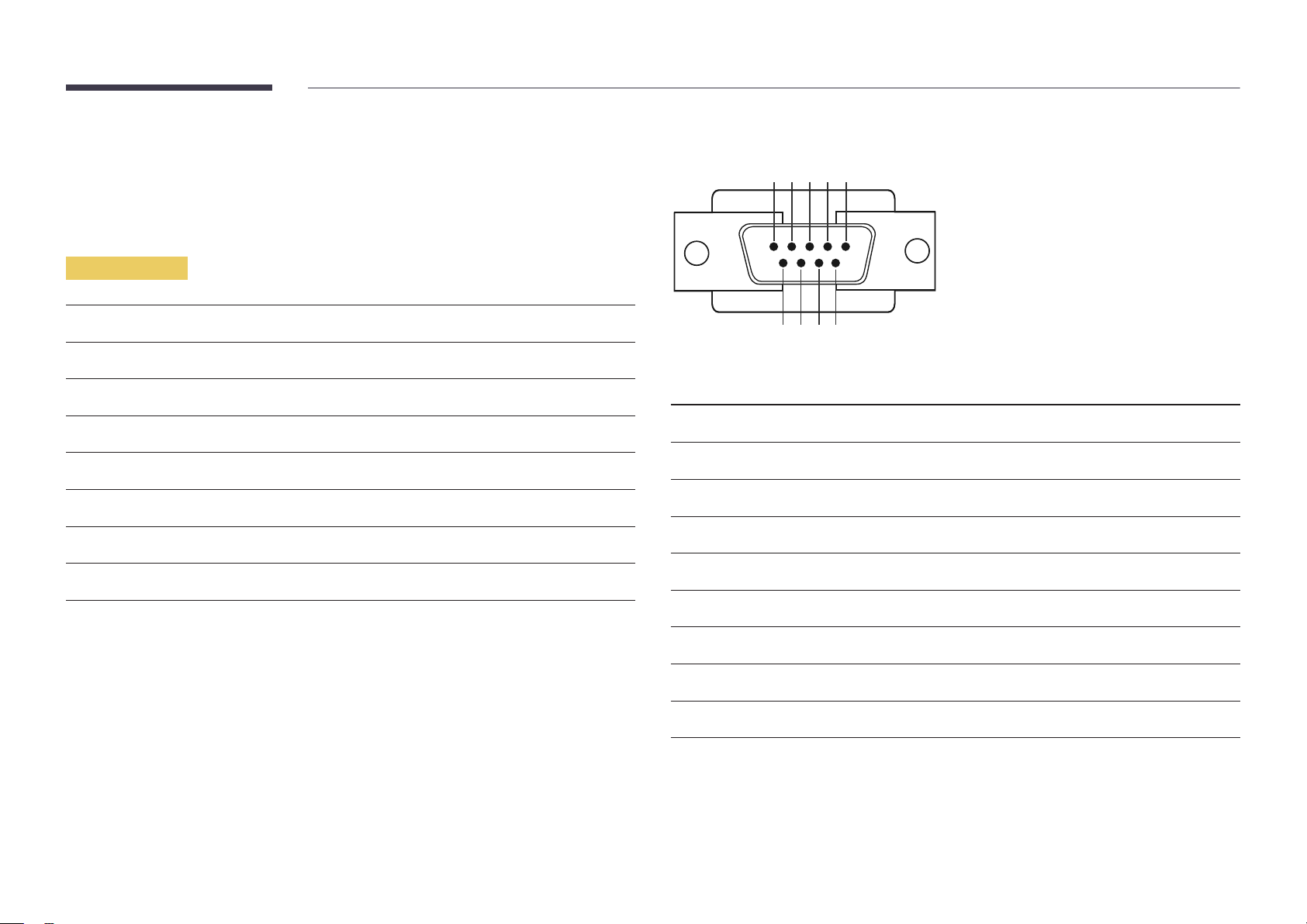
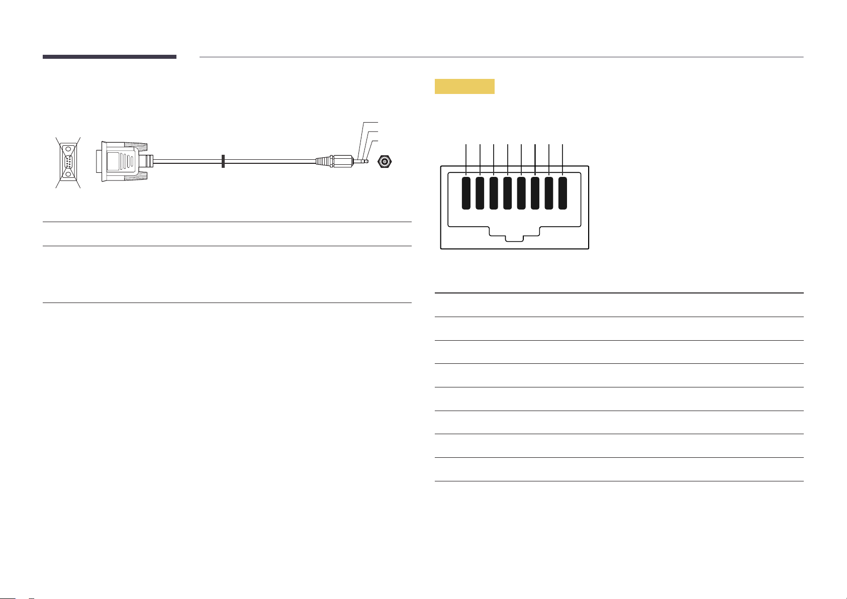
Remote Control (RS232C)
Cable Connection
RS232C Cable
•
Pin assignment
1 2 3 4 5
Interface
Pin
Bit rate
Data bits
Parity
Stop bit
Flow control
Maximum length
RS232C (9 pins)
TxD (No.2), RxD (No.3), GND (No.5)
9600 bps
8 bit
None
1 bit
None
15 m (only shielded type)
6 7 8 9
Pin Signal
1
2
3
4
5
6
7
8
9
Detect data carrier
Received data
Transmitted data
Prepare data terminal
Signal ground
Prepare data set
Send request
Clear to send
Ring indicator
24
•
RS232C cable
Connector: 9-Pin D-Sub to Stereo Cable
59
1
6
-P1-
-P1- -P1- -P2- -P2-
3
2
1
-P2-
LAN Cable
•
Pin assignment
1 2 3 4 5 6 7 8
Female Rx
Tx
Gnd
2
3
5
-------->
<--------
----------
3
2
5
Tx
Rx
Gnd
STEREO
PLUG
(3.5ø)
Pin No Standard Color Signal
1 White and orange TX+
2 Orange TX-
3 White and green RX+
4 Blue NC
5 White and blue NC
6 Green RX-
7 White and brown NC
8 Brown NC
25

•
Connector : RJ45
Direct LAN cable (PC to HUB)
Cross LAN cable (PC to PC)
HUB
P1P2
RJ45 RJ45 MDC
Signal
TX+
TX-
RX+
RX-
P1
P1 P2 Signal
1 <--------> 1 TX+
2 <--------> 2 TX-
3 <--------> 3 RX+
6 <--------> 6 RX-
P2
Signal
TX+
TX-
RX+
RX-
RJ45
P1 P2
P1 P2 Signal
1 <--------> 3 RX+
2 <--------> 6 RX-
3 <--------> 1 TX+
6 <--------> 2 TX-
26

Connection
―
Ensure you connect each of the adapters to the correct RS232C IN or OUT port on the product.
•
Connection 1
•
Connection 2
RJ45 RJ45
RS232C
IN OUT
RS232C
IN OUT
RS232C
IN OUT
RS232C
IN OUT
•
Connection 3
RS232C
RJ45 RS232C
OUT
IN OUT
RS232C
IN OUT
RS232C
IN OUT
27

Control Codes
No. Command type Command Value range
Viewing control state (Get control command)
Header Command ID Data length Checksum
0xAA Command type 0
Controlling (Set control command)
Header Command ID Data length Data Checksum
0xAA Command type 1 Value
Command
No. Command type Command Value range
1
2
3
4
Power control 0x11 0~1
Volume control 0x12 0~100
Input source control 0x14 -
Screen mode control 0x18 -
10
•
All communications take place in hexadecimals. The checksum is calculated by adding up all
values except the header. If a checksum adds up to be more than 2 digits as shown below
(11+FF+01+01=112), the first digit is removed.
E.g. Power On & ID=0
Header Command ID Data length Data 1 Checksum
0xAA 0x11 1 "Power"
Header Command ID Data length Data 1 12
0xAA 0x11 1 1
•
To control all devices connected by a serial cable simultaneously irrespective of IDs, set the ID as
"0xFE" and transmit commands. Commands will be executed by each device but ACK will not
respond.
Video Wall User Control 0x89 -
5
6
7
8
9
Screen size control 0x19 0~255
Auto adjustment control (PC and
BNC only)
Video wall mode control 0x5C 0~1
Safety Lock 0x5D 0~1
Video Wall On 0x84 0~1
0x3D 0
28

Power control
Volume control
•
Function
A product can be powered on and off using a PC.
•
Viewing power state (Get Power ON / OFF Status)
Header Command ID Data length Checksum
0xAA 0x11 0
•
Setting power ON/Off (Set Power ON / OFF)
Header Command ID Data length Data Checksum
0xAA 0x11 1 "Power"
"Power": Power code to be set on a product.
1: Power ON
0: Power OFF
•
Ack
Header Command ID Data length Ack/Nak r-CMD Val1 Checksum
0xAA 0xFF 3 'A' 0x11 "Power"
"Power": Power code to be set on a product.
•
Nak
Header Command ID Data length Ack/Nak r-CMD Val1 Checksum
•
Function
The volume of a product can be adjusted using a PC.
•
Viewing volume state (Get Volume Status)
Header Command ID Data length Checksum
0xAA 0x12 0
•
Setting the volume (Set Volume)
Header Command ID Data length Data Checksum
0xAA 0x12 1 "Volume"
"Volume": Volume value code to be set on a product. (0-100)
•
Ack
Header Command ID Data length Ack/Nak r-CMD Val1 Checksum
0xAA 0xFF 3 'A' 0x12 "Volume"
"Volume": Volume value code to be set on a product. (0-100)
•
Nak
Header Command ID Data length Ack/Nak r-CMD Val1 Checksum
0xAA 0xFF 3 'N' 0x12 "ERR"
0xAA 0xFF 3 'N' 0x11 "ERR"
"ERR" : A code showing what error has occurred.
"ERR" : A code showing what error has occurred.
29
 Loading...