


Model : |
SR-S2026C |
(D |
) |
SR-S2226C |
|
SR-S2027C |
(D |
) |
SR-S2227C |
|
SR-S2028C |
(D |
) |
SR-S2228C |
|
SR-S2029C |
(D |
) |
SR-S2229C |
SR-S2025C(D)
SR-S20NTC(D) SR-S22NTC(D)
SR-S20BTC(D) SR-S22BTC(D)
SR-S20DTC(D) SR-S22DTC(D)
SR-S20FTC(D) SR-S22FTC(D)
SR-S20YTC(D)
(D ) (D ) (D ) (D )
REFRIGERATOR |
|
Contents |
1. |
Product Specification |
|
2. |
Safety Warning & Caution |
|
3. |
Specification of Electric Components |
|
4. |
Circuit Diagram |
|
5. |
Dimension & Part Name of Refrigerator |
|
6. |
Freezing Cycle & Cold Air Circulation |
|
|
|
Course in Refrigerator |
7. |
Function & Operating Instruction of Refrigerator |
|
8. Operating Principle of Circuit |
||
9. |
Trouble Checkup & Repair Method |
|
10. Operation Principle & Repair Method of ICE-MAKER |
||
11. |
Reference |
|
12. |
Disassembly Method of Freezer & Refrigerator |
|
13. |
Method of Hinge up Assembly & Disassembly |
|
14. |
Refrigerator Exploded view & List |
|
15. |
Machine Room Assembly Specification |
|
16. Disassembly & Assembly Method of Internal Part of |
||
|
|
Electric Field Box |
17. |
Installation Method of Water Supply Tube |
|
18. Installation of the Water Dispenser Line
19. PCB Circuit Diagram and Service Components List
20. Specification of Principal Part of Circuit

1. Product Specifications
|
Item |
|
|
|
|
|
|
|
Specification |
|
|
|
|
|
|
|
|
|
||||
|
|
|
|
|
|
|
|
|
|
|
|
|
|
|
|
|
||||||
|
|
|
SR-S2026C(D) |
|
SR-S2025C(D) |
|
SR-S2027C(D) |
SR-S2028C(D) |
|
SR-S2029C(D) |
|
|
|
|||||||||
|
Model |
SR-S20NTC(D) |
|
SR-S20YTC(D) |
|
SR-S20BTC(D) |
SR-S20DTC(D) |
|
SR-S20FTC(D) |
|
|
|
||||||||||
|
|
|
Basic |
|
|
Water Dispenser |
|
|
|
Basic & |
H/B |
Dispenser |
|
|
|
Dispenser |
& |
H/B |
|
|
||
|
|
|
|
|
|
|
|
|
|
|
|
|
|
|
|
|
|
|
|
|
|
|
|
|
Total |
562 |
l |
|
|
547 |
l |
|
|
|
|
|
540 |
l |
|
|
|
|
|
|
|
|
|
|
|
|
|
|
|
|
|
|
|
|
|
|
|
|
|
|
|
|
|
|
Net Capacity |
|
Refrigerator |
349 |
l |
|
|
336 |
l |
|
|
|
|
|
349 |
l |
|
|
|
|
|
|
|
|
|
Freezer |
213 |
l |
|
|
211 |
l |
|
|
|
|
|
191 |
l |
|
|
|
|
|
|
|
Net dimension(W×H×D) |
|
|
|
|
908mm |
|
719(724)mm |
|
1760mm |
|
|
|
|
|
|
|
|
|||||
|
|
|
|
|
|
|
|
|
|
|
|
|
|
|
|
|
|
|
|
|
||
Rated Frequency and Frequency |
|
|
|
|
|
|
230 |
240V/50Hz |
|
|
|
|
|
|
|
|
|
|||||
|
|
|
|
|
|
|
|
|
|
|
|
|
|
|
|
|
|
|
|
|
||
Motor Rated Consumption Power |
|
|
155W |
|
|
|
|
|
|
|
160W |
|
|
|
|
|
|
|||||
|
|
|
|
|
|
|
|
|
|
|
|
|
|
|
|
|
|
|
|
|||
Electric Heater Rated Consumption Power |
400W |
|
|
410W |
|
412W |
412W |
422W |
|
|
|
|
|
|
||||||||
|
|
|
|
|
|
|
|
|
|
|
|
|
|
|
|
|
|
|||||
Kind of Refrigerator |
|
|
|
|
Indirect Cooling Method Refrigerator |
|
|
|
|
|
|
|
|
|
||||||||
|
|
|
|
|
|
|
|
|
|
|
|
|
|
|
|
|
|
|
|
|
||
Refrigerant |
|
|
|
|
|
|
|
|
HFC-134a |
|
|
|
|
|
|
|
|
|
||||
|
|
|
|
|
|
|
|
|
|
|
|
|
|
|
|
|
|
|
|
|
||
Refrigerant Input Amount |
|
|
|
|
|
|
|
|
190gr |
|
|
|
|
|
|
|
|
|
||||
|
|
|
|
|
|
|
|
|
|
|
|
|
|
|
|
|
|
|
|
|
|
|
Freezer Performance |
|
|
|
|
|
|
|
|
|
|
(4-STAR) |
|
|
|
|
|
|
|
|
|||
|
|
|
|
|
|
|
|
|
|
|
|
|
|
|
|
|
|
|||||
|
|
|
|
|
|
|
|
|
|
|
|
|
|
|
|
|
|
|
|
|
|
|
Product Weight |
111Kg |
|
|
|
|
|
|
|
111Kg |
117Kg |
117Kg |
|
|
|
|
|
||||||
|
|
|
|
|
|
|
|
|
|
|
|
|
|
|
|
|
|
|
|
|
||
|
|
|
|
|
|
|
|
|
|
|
|
|
|
|
|
|
|
|
|
|
|
|
|
Item |
|
|
|
|
|
|
|
Specification |
|
|
|
|
|
|
|
|
|
||||
|
|
|
|
|
|
|
|
|
|
|
|
|
|
|
|
|
||||||
|
|
|
SR-S2226C(D) |
|
|
SR-S2227C(D) |
|
|
SR-S2228C(D) |
|
|
SR-S2229C(D) |
|
|
|
|
||||||
Model Name |
SR-S22NTC(D) |
|
|
SR-S22BTC(D) |
|
SR-S22DTC(D) |
|
|
SR-S22FTC(D) |
|
|
|
||||||||||
|
|
|
Basic |
|
|
Basic |
& |
|
H/B |
|
Dispenser |
|
|
Dispenser |
& |
H/B |
|
|
||||
|
|
|
|
|
|
|
|
|
|
|
|
|
|
|
|
|
|
|
|
|
|
|
|
|
Total Inside Capacity |
|
|
|
599 l |
|
|
|
|
|
|
|
569 l |
|
|
|
|
||||
Net Inside |
|
|
|
|
|
|
|
|
|
|
|
|
|
|
|
|
|
|
|
|
|
|
|
Freezer |
|
|
227 |
l |
|
|
|
|
|
|
|
197 |
l |
|
|
|
|
||||
Capacity |
|
|
|
|
|
|
|
|
|
|
|
|
|
|
||||||||
|
|
Refrigerator |
|
|
372 |
l |
|
|
|
|
|
|
|
372 |
l |
|
|
|
|
|||
|
|
|
|
|
|
|
|
|
|
|
|
|
|
|
|
|
|
|
|
|
||
Outer Size (width |
|
depth height) |
|
|
|
|
908mm |
|
754(759)mm |
|
1760mm |
|
|
|
|
|
|
|
|
|||
|
|
|
|
|
|
|
|
|
|
|
|
|
|
|
|
|
|
|
||||
Rated Frequency and Frequency |
|
|
|
|
|
|
230 |
240V/50Hz |
|
|
|
|
|
|
|
|
|
|||||
|
|
|
|
|
|
|
|
|
|
|
|
|
|
|
|
|
|
|
||||
Motor Rated Consumption Power |
|
|
155W |
|
|
|
|
|
|
|
160W |
|
|
|
|
|
|
|||||
|
|
|
|
|
|
|
|
|
|
|
|
|
|
|
|
|
|
|
||||
Electric Heater Rated Consumption Power |
400W |
|
|
410W |
|
|
|
|
412W |
|
422W |
|
|
|
|
|
|
|
||||
|
|
|
|
|
|
|
|
|
|
|
|
|
|
|
|
|
||||||
Kind of |
Refrigerator |
|
|
|
|
Indirect Cooling Method Refrigerator |
|
|
|
|
|
|
|
|
|
|||||||
|
|
|
|
|
|
|
|
|
|
|
|
|
|
|
|
|
|
|
|
|||
Refrigerant |
|
|
|
|
|
|
|
|
HFC-134a |
|
|
|
|
|
|
|
|
|
||||
|
|
|
|
|
|
|
|
|
|
|
|
|
|
|
|
|
|
|
|
|||
Refrigerant Input Amount |
|
|
|
|
|
|
|
|
190gr |
|
|
|
|
|
|
|
|
|
||||
|
|
|
|
|
|
|
|
|
|
|
|
|
|
|
|
|
|
|
|
|||
Freezer Performance |
|
|
|
|
|
|
|
|
|
|
(4-STAR) |
|
|
|
|
|
|
|
|
|||
|
|
|
|
|
|
|
|
|
|
|
|
|
|
|
|
|
|
|||||
|
|
|
|
|
|
|
|
|
|
|
|
|
|
|
|
|
|
|
|
|
|
|
Product Weight |
121Kg |
|
|
121Kg |
|
|
|
127Kg |
|
127Kg |
|
|
|
|
||||||||
|
|
|
|
|
|
|
|
2 |
||||||||||||||
|
|
|
|
|
|
|
|
|
|
|
|
|
|
|
|
|
|
|
|
|
|
|
|
|
|
|
|
|
|
|
|
|
|
|
|
|
|
|
|
|
|
|
|
|
|
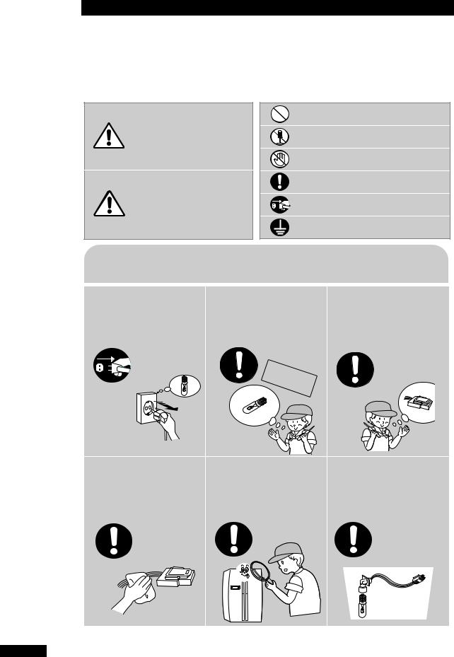
2. SAFETY WARNINGS
Read all instructions before using this product and keep to the instructions in order to prevent danger or property damage.
CAUTION/WARNING SYMBOLS DISPLAYED SYMBOLS
Indicates that a
danger of death Warning or serious injury
exists.
Indicates that a risk
of personal injury Caution or material damage
exists.
means “Prohibition”.
means “Do not disassemble”.
means “No contact”.
means ”The things to be followed”.
means “Power cord should be unplugged from the consent”
means “Earth to prevent Electric shock”.
 Warning & Caution
Pull the power plug out to exchange the interior lamp of the refrigerator.
● It may cause electric shock.
Unplug
Use the rated components |
On repair,make sure that the |
on the replacement. |
wires such as harness are |
● Check the correct model,rated |
bundled tightly. |
voltage,rated current,operating |
● Bundle tightly wires in order not to |
temperature and so on. |
be detached by the external force and |
|
then not to be wetted. |
Rated |
|
components |
|
On repair,remove completely |
After repair,check the |
Check if there is any trace |
|||||
dust or other things of |
assembled state of |
indicating the permeation |
|||||
housing parts,harness parts, |
components. |
of water. |
|||||
and check parts. |
●It must be in the same assembled |
● If there is that kind of trace,change |
|||||
● Cleaning may prevent the possible |
state when compared with the state |
the related components or do the |
|||||
fire by tracking or short. |
before disassembly. |
|
|
necessary treatment such |
|||
|
|
|
|
|
as taping using the |
||
|
|
|
|
|
insulating tape. |
||
|
|
|
|
|
|
|
|
|
|
|
|
|
|
|
|
|
|
|
|
|
|
|
|
3
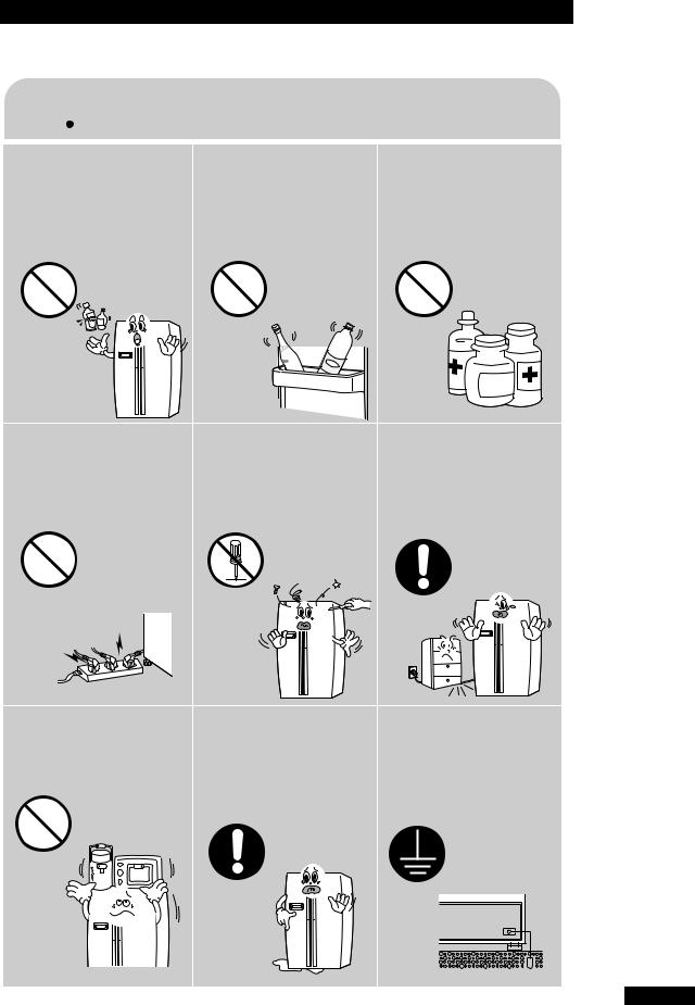
Place let users know in detail.
 Warning & Caution
Do not allow users to put |
Do not allow users to store |
Do not allow users to store |
bottles or kinds of glass in |
narrow and lengthy bottles |
pharmaceutical products, |
the freezer. |
or foods in a small multi- |
scientific materials, |
● Freezing of the contents may inflict a |
purpose room. |
etc., in the refrigerator. |
● It may hurt users when refrigerator |
● The products which temperature |
|
wound. |
door is opened and closed resulting in |
control should not be stored in the |
|
||
|
falling stuff down. |
refrigerator. |
Prohibition |
Prohibition |
Prohibition |
Do not allow users to insert |
Do not allow users to |
Do not allow users to bend |
the power plugs for many |
disassemble, repair or alter. |
the power cord with |
products at the same time. |
● It may cause fire or abnormal |
excessive force or do not |
● May cause abnormal generation of |
operation which leads to injury. |
have the power cord pressed |
heat or fire. |
|
by heavy article. |
|
|
● May cause fire. |
Prohibition |
Do not |
|
disassemble |
Do not allow users to store |
Do not allow users to install |
Make sure of the earth. |
articles on the product. |
the refrigerator in the wet |
● If earthing is not done, it will cause |
● Opening or closing the door may |
place or the place which |
breakdown and electric shock. |
cause things to fall down, with may |
water splashes. |
|
inflict a wound. |
● Deterioration of insulation of |
|
|
|
|
|
electric parts may cause electric |
|
|
shock or fire. |
|
Prohibition
Earth
4
3. Specifications of Electric Components
Components for Freezer
Room Temperature Sensor Components
Defrost Related Components
|
Items |
|
|
|
|
Models |
|
|
|
|
Freezing Capacity |
|
|
|
|
|
|
|
Model |
|
|
|
|
|
|
Compressor |
|
|
Starting type |
|
|
|
|
Oil Charge |
|
Evaporator |
|
|
Freezer |
|
|
|
Refrigerator |
|
|
|
|
|
|
|
|
|
|
|
|
Condenser |
|
|
|
|
Dryer |
|
|
|
|
Capillary tube |
|
|
|
|
Refrigerant |
|
|
|
|
Model |
|
Temperature Selection |
|
|
|
|||
Freezer |
THERMISTOR |
|
-26 |
|
|
|
|||
|
|
|
||
|
(F-SENSOR) |
|
-20 |
|
|
502AT |
|
-14 |
|
|
|
|
|
|
|
Model |
|
Temperature Selection |
|
Refrigerator |
THERMISTOR |
|
-1 |
|
|
|
|||
502AT |
|
3 |
||
|
(R-SENSOR) |
|
||
|
|
|
|
7 |
|
|
|
|
|
First Defrost Cycle (Concurrent defrost of F and R)
Cycle |
Defrost Cycle(FRE) |
|
||
Defrost Cycle(REF) |
|
|||
Defrost |
|
|||
Pause time |
|
|||
|
|
|||
|
F Defrost- |
|
Model |
|
|
|
|||
|
|
|
||
|
Sensor |
|
SPEC |
|
Sensor |
|
|
||
R Defrost- |
|
Model |
||
Defrost |
|
|
||
Sensor |
|
SPEC |
||
Thermal-Fuse |
|
Rated |
||
Operating temperature |
||||
|
|
|||
|
|
|
|
|
Specification
SR-S20.. SR-S22..
(4 STAR)
DK182Q-L2U
R.S.C.R
FREOL α- 15 (ESTER)
SPLIT FIN TYPE
SPLIT FIN TYPE
Forced and natural convection type
Molecular sieve XH-9
0.82 ×3000, 5.5 Kg/cm 2
HFC-134a |
||
ON( ) |
|
OFF( ) |
|
||
-25.0 |
|
-27.0 |
-19.0 |
|
-21.0 |
-13.0 |
|
-15.0 |
ON( ) |
|
OFF( ) |
0.0 |
|
-2.0 |
4.0 |
|
2.0 |
8.0 |
|
6.0 |
|
|
|
4 hr |
± 10 min |
|
12 ~ 24 hr (vary according to the conditions used)
6 ~ 12 hr (vary according to the conditions used)
10 ± 2 min
THERMISTOR (502AT)
5.0 at 25
THERMISTOR (502AT)
5.0 at 25
AC 250V 10A
77 ± 4
5

|
|
|
|
|
|
|
|
|
|
|
|
|
|
|
|
|
|
|
|
|
|
|
|
|
|
|
|
|
|
|
|
|
|
|
|
|
Items |
|
|
Specifications |
|
|
|
|
|
|||||
|
|
|
Model |
SR-S2026, S2226 |
SR-S20YTC, |
|
SR-S2027, S2227 |
|
SR-S2028, S2228 |
|
SR-S2029, S2229 |
|
||||
|
|
|
SR-S20NTC,S22NTC |
SR-S2025 |
|
SR-S20BTC,S22BTC |
|
SR-S20DTC,S22DTC |
|
SR-S20FTC,S22FTC |
|
|||||
|
|
|
|
|
|
|
|
|
|
|||||||
|
|
Defrost-Heater(FRE) |
|
Conducting at F Defrosting |
|
230 W |
|
|
|
|
|
230 W |
|
|||
|
|
Defrost-Heater(REF) |
|
Conducting at R Defrosting |
|
110 W |
|
|
|
|
|
110 W |
|
|||
|
|
DRAIN Heater(FRE) |
|
Conducting at F Defrosting |
|
|
41 W |
|
|
|
|
|
41 W |
|
||
|
|
DRAIN Heater(REF) |
|
Conducting at R Defrosting |
|
|
25 W |
|
|
|
|
|
25 W |
|
||
|
|
DISPENSER Heater |
|
Interlock with F-FAN |
- |
|
|
|
- |
|
|
5W |
|
5W |
|
|
|
|
HOME-BAR Heater |
|
Interlock with COMP |
- |
|
|
|
10W |
|
|
- |
|
10W |
|
|
|
|
Thermal-Fuse for preventing |
|
|
|
|
|
|
|
|
|
|
|
|||
|
|
overheating of Freezer Defrost-Heater |
|
|
AC 250V |
|
10A 72 |
|
±4 |
|
||||||
|
|
|
|
|
|
|
|
|
|
|
||||||
|
|
Thermal-Fuse for preventing |
|
|
|
|
|
|
|
|
|
|
|
|||
|
|
overheating of Refrigerator Defrost-Heater |
|
|
|
|
|
|
|
|
|
|
|
|||
|
|
|
|
|
|
|
|
|
|
|
|
|
|
|
||
|
|
Compressor |
|
|
|
|
DK182Q-L2U |
|
|
|
|
|
||||
|
|
|
|
|
|
|
|
|
|
|
|
|
|
|
|
|
|
|
Condenser for |
|
|
Running |
|
|
|
|
350VAC-5 |
μF |
|
|
|
||
|
|
COMP |
|
|
|
|
|
|
|
|
|
|
|
|
|
|
|
|
|
|
Starting |
|
|
|
|
|
|
|
|
|
|
|
|
|
|
(Package type) |
|
|
|
|
|
|
|
- |
|
|
|
|
|
|
|
|
Starting-Relay |
|
|
Model |
|
|
|
J531Q35E330M385-2 |
|
|
|
|
|
||
|
|
|
|
|
|
|
|
|
|
|
|
|
|
|
|
|
|
Components |
|
|
Operation |
|
|
|
|
33 Ω±20% |
|
|
|
||||
|
|
|
|
|
|
|
|
|
|
|
||||||
|
|
|
|
|
|
|
|
|
|
|
|
|
|
|
|
|
|
|
|
|
Model |
|
|
|
|
4TM265RFBYY-53 |
|
|
|
|
|
||
|
|
|
|
|
|
|
|
|
|
|
|
|
|
|||
|
|
Over-load Relay |
|
|
|
|
|
|
|
|
|
|
|
|
|
|
|
Electric |
|
|
Temp. ON |
|
|
|
130 |
±5 |
|
|
|
||||
|
|
|
|
|
|
|
|
|
|
|
|
|
|
|||
|
|
|
|
Temp. OFF |
|
|
|
|
69 ±9 |
|
|
|
||||
|
|
|
|
|
|
|
|
|
|
|
|
|
|
|||
|
|
Rated Voltage |
|
|
|
|
230V/50,60Hz |
|
|
|
||||||
|
|
|
|
|
|
|
|
|
|
|
|
|
||||
|
|
MOTOR-BLDC(FRE) |
|
|
240V/50Hz UDQMOO2H4ASS |
|
|
|
||||||||
|
|
|
|
|
|
|
|
|
|
|
|
|
||||
|
|
MOTOR-BLDC(REF) |
|
|
240V/50Hz UDQMOO2H4ASS |
|
|
|
||||||||
|
|
|
|
|
|
|
|
|
|
|
|
|
||||
|
|
MOTOR-BLDC (Circuit) |
|
|
240V/50Hz UDQMOO2H4ASS |
|
|
|
||||||||
|
|
|
|
|
|
|
|
|
|
|
|
|
|
|
|
|
|
|
|
Lamp(FRE) |
|
|
|
|
AC240V/25W |
|
|
|
|
|
|||
|
|
|
|
|
|
|
|
|
|
|
|
|
|
|
|
|
|
|
|
Lamp(REF) |
|
|
|
AC240V/25W |
×2 |
|
|
|
|||||
|
|
|
|
|
|
|
|
|
|
|
|
|
|
|
|
|
|
|
|
Door Switch |
|
|
|
AC250V 0.5A |
×2 |
|
|
|
|||||
|
|
|
|
|
|
|
|
|
|
|
|
|
|
|
|
|
|
|
Door Switch (HOME-BAR) |
|
|
|
|
AC250V |
0.5A |
|
|
|
|
|
|||
|
|
|
|
|
|
|
|
|
|
|
|
|
|
|
||
|
|
Dispenser Switch |
|
|
|
DECO 250VAC 6A |
|
|
|
|
|
|||||
|
|
|
|
|
|
|
|
|
|
|
|
|
|
|
|
|
|
|
|
Power cord |
|
|
|
|
AC250V |
12A |
|
|
|
|
|
||
|
|
|
|
|
|
|
|
|
|
|
|
|
|
|
||
|
|
|
Earth Screw |
|
|
BSBN (BRASS SCREW) |
|
|
|
|
|
|||||
|
|
|
|
|
|
|
|
|
|
|
|
|
|
|
|
|
|
|
|
|
|
|
|
|
|
|
|
|
|
|
|
|
|
6
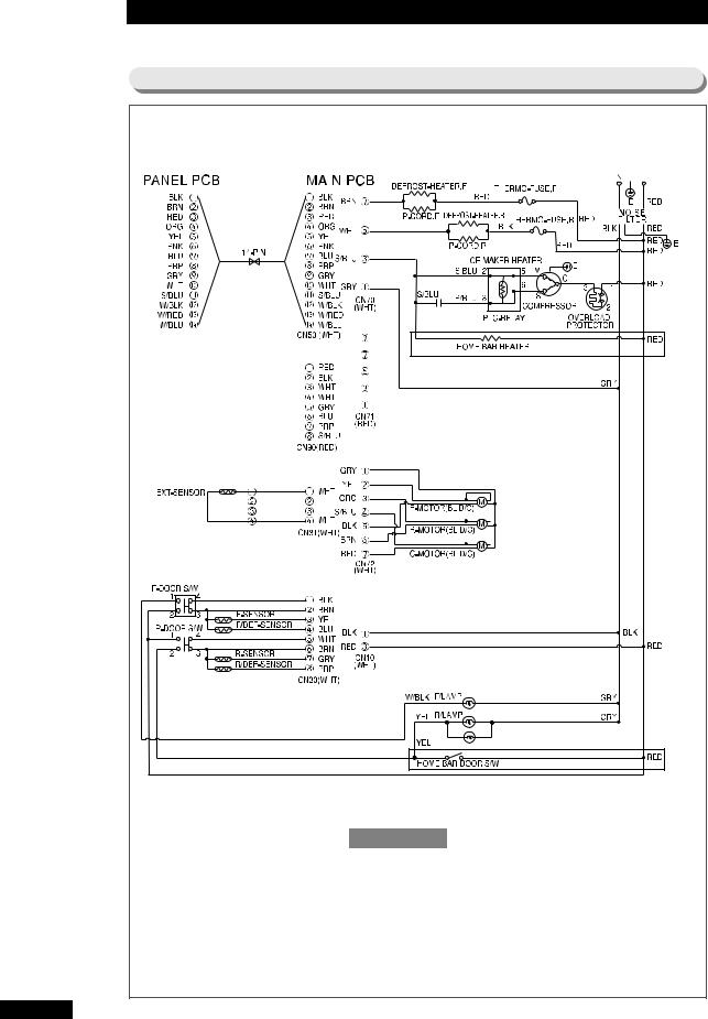
4. Circuit Diagram
For Basic |
|
|
With Home Bar Models |
|
|
|
|
(SR-S2025, S20YTC, S2026, S2027, S2226, S2227/S20NTC,S20BTC,S22NTC,S22BTC) |
|
|
|
|||||||||||||
|
|
|
|
|
|
|
|
|
|
|
|
|
|
|
|
|
|
|
|
|
|
|
|
|
|
|
|
|
|
|
|
|
|
|
|
|
|
|
|
|
|
|
|
|
|
|
|
|
|
|
|
|
|
|
|
|
|
|
|
|
|
|
|
|
|
|
|
|
|
|
|
|
|
|
|
|
|
|
|
|
|
|
|
|
|
|
|
|
|
|
|
|
|
|
|
|
|
|
|
|
|
|
|
|
|
|
|
|
|
|
|
|
|
|
|
|
|
|
|
|
|
|
|
|
|
|
|
|
|
|
|
|
|
|
|
|
|
|
|
|
|
|
|
|
|
|
|
|
|
|
|
|
|
|
|
|
|
|
|
|
|
|
|
|
|
|
|
|
|
|
|
|
|
|
|
|
|
|
|
|
|
|
|
|
|
|
|
|
|
|
|
|
|
|
|
|
|
|
|
|
|
|
|
|
|
|
|
|
|
|
|
|
|
|
|
|
|
|
|
|
|
|
|
|
|
|
|
|
|
|
|
|
|
|
|
|
|
|
|
|
|
|
|
|
|
|
|
|
|
|
|
|
|
|
|
|
|
|
|
|
|
|
|
|
|
|
|
|
|
|
|
|
|
|
|
|
|
|
|
|
|
|
|
|
|
|
|
|
|
|
|
|
|
|
|
|
|
|
|
|
|
|
|
|
|
|
|
|
|
|
|
|
|
|
|
|
|
|
|
|
|
|
|
|
|
|
|
|
|
|
|
|
|
|
|
|
|
|
|
|
|
|
|
|
|
|
|
|
|
|
|
|
|
|
|
|
|
|
|
|
|
|
|
|
|
|
|
|
|
|
|
|
|
|
|
|
|
|
|
|
|
|
|
|
|
|
|
|
|
|
|
|
|
|
|
|
|
|
|
|
|
|
|
|
|
|
|
|
|
|
|
|
|
|
|
|
|
|
|
|
|
|
|
|
|
|
|
|
|
|
|
|
|
|
|
|
|
|
|
|
|
|
|
|
|
|
|
|
|
|
|
|
|
|
|
|
|
|
|
|
|
|
|
|
|
|
|
|
|
|
|
|
|
|
|
|
|
|
|
|
|
|
|
|
|
|
|
|
|
|
|
|
|
|
|
|
|
|
|
|
|
|
|
|
|
|
|
|
|
|
|
|
|
|
|
|
|
|
|
|
|
|
|
|
|
|
|
|
|
|
|
|
|
|
|
|
|
|
|
|
|
|
|
|
|
|
|
|
|
|
|
|
|
|
|
|
|
|
|
|
|
|
|
|
|
|
|
|
|
|
|
|
|
|
|
|
|
|
|
|
|
|
|
|
|
|
|
|
|
|
|
|
|
|
|
|
|
|
|
|
|
|
|
|
|
|
|
|
|
|
|
|
|
|
|
|
|
|
|
|
|
|
|
|
|
|
|
|
|
|
|
|
|
|
|
|
|
|
|
|
|
|
|
|
|
|
|
|
|
|
|
|
|
|
|
|
|
|
|
|
|
|
|
|
|
|
|
|
|
|
|
|
|
|
|
|
|
|
|
|
|
|
|
|
|
|
|
|
|
|
|
|
|
|
|
|
|
|
|
|
|
|
|
|
|
|
|
|
|
|
|
|
|
|
|
|
|
|
|
|
|
|
|
|
|
|
|
|
|
|
|
|
|
|
|
|
|
|
|
|
|
|
|
|
|
|
|
|
|
|
|
|
|
|
|
|
|
|
|
|
|
|
|
|
|
|
|
|
|
|
|
|
|
|
|
|
|
|
|
|
|
|
|
|
|
|
|
|
|
|
|
|
|
|
|
|
|
|
|
|
|
|
|
|
|
|
|
|
|
|
|
|
|
|
|
|
|
|
|
|
|
|
|
|
|
|
|
|
|
|
|
|
|
|
|
|
|
|
|
|
|
|
|
|
|
|
|
|
|
Reference
RED-RED BLU-BLUE ORG-ORANGE
P/BLU-PINK/BLUE BRN-BROWN
PNK-PINK
GRY-GRAY W/BLU-WHITE/BLUE
WHT-WHITE
YEL-YELLOW
BLK-BLACK
PRP-PURPLE W/BLK-WHITE/BLACK S/BLU-SKY/BLUE E-EARTH W/RED-WHITE/RED
7

|
|
|
|
|
|
|
|
|
|
|
|
|
|
|
|
|
|
|
|
|
|
|
|
|
|
|
|
|
|
|
|
|
|
|
|
|
|
|
|
|
|
|
|
|
|
|
|
|
|
|
|
|
|
|
|
|
|
For Dispenser |
|
|
With Home Bar Models |
|
|
|
(SR-S2028, S2029 S2228, S2229/S20DTC, S20FTC,S22DTC,S22FTC) |
||||||||||||||||||||||||||||||||||||||||||||||||||
|
|
|
|
|
|
|
|
|
|
|
|
|
|
|
|
|
|
|
|
|
|
|
|
|
|
|
|
|
|
|
|
|
|
|
|
|
|
|
|
|
|
|
|
|
|
|
|
|
|
|
|
|
|
|
|
|
|
|
|
|
|
|
|
|
|
|
|
|
|
|
|
|
|
|
|
|
|
|
|
|
|
|
|
|
|
|
|
|
|
|
|
|
|
|
|
|
|
|
|
|
|
|
|
|
|
|
|
|
|
|
|
|
|
|
|
|
|
|
|
|
|
|
|
|
|
|
|
|
|
|
|
|
|
|
|
|
|
|
|
|
|
|
|
|
|
|
|
|
|
|
|
|
|
|
|
|
|
|
|
|
|
|
|
|
|
|
|
|
|
|
|
|
|
|
|
|
|
|
|
|
|
|
|
|
|
|
|
|
|
|
|
|
|
|
|
|
|
|
|
|
|
|
|
|
|
|
|
|
|
|
|
|
|
|
|
|
|
|
|
|
|
|
|
|
|
|
|
|
|
|
|
|
|
|
|
|
|
|
|
|
|
|
|
|
|
|
|
|
|
|
|
|
|
|
|
|
|
|
|
|
|
|
|
|
|
|
|
|
|
|
|
|
|
|
|
|
|
|
|
|
|
|
|
|
|
|
|
|
|
|
|
|
|
|
|
|
|
|
|
|
|
|
|
|
|
|
|
|
|
|
|
|
|
|
|
|
|
|
|
|
|
|
|
|
|
|
|
|
|
|
|
|
|
|
|
|
|
|
|
|
|
|
|
|
|
|
|
|
|
|
|
|
|
|
|
|
|
|
|
|
|
|
|
|
|
|
|
|
|
|
|
|
|
|
|
|
|
|
|
|
|
|
|
|
|
|
|
|
|
|
|
|
|
|
|
|
|
|
|
|
|
|
|
|
|
|
|
|
|
|
|
|
|
|
|
|
|
|
|
|
|
|
|
|
|
|
|
|
|
|
|
|
|
|
|
|
|
|
|
|
|
|
|
|
|
|
|
|
|
|
|
|
|
|
|
|
|
|
|
|
|
|
|
|
|
|
|
|
|
|
|
|
|
|
|
|
|
|
|
|
|
|
|
|
|
|
|
|
|
|
|
|
|
|
|
|
|
|
|
|
|
|
|
|
|
|
|
|
|
|
|
|
|
|
|
|
|
|
|
|
|
|
|
|
|
|
|
|
|
|
|
|
|
|
|
|
|
|
|
|
|
|
|
|
|
|
|
|
|
|
|
|
|
|
|
|
|
|
|
|
|
|
|
|
|
|
|
|
|
|
|
|
|
|
|
|
|
|
|
|
|
|
|
|
|
|
|
|
|
|
|
|
|
|
|
|
|
|
|
|
|
|
|
|
|
|
|
|
|
|
|
|
|
|
|
|
|
|
|
|
|
|
|
|
|
|
|
|
|
|
|
|
|
|
|
|
|
|
|
|
|
|
|
|
|
|
|
|
|
|
|
|
|
|
|
|
|
|
|
|
|
|
|
|
|
|
|
|
|
|
|
|
|
|
|
|
|
|
|
|
|
|
|
|
|
|
|
|
|
|
|
|
|
|
|
|
|
|
|
|
|
|
|
|
|
|
|
|
|
|
|
|
|
|
|
|
|
|
|
|
|
|
|
|
|
|
|
|
|
|
|
|
|
|
|
|
|
|
|
|
|
|
|
|
|
|
|
|
|
|
|
|
|
|
|
|
|
|
|
|
|
|
|
|
|
|
|
|
|
|
|
|
|
|
|
|
|
|
|
|
|
|
|
|
|
|
|
|
|
|
|
|
|
|
|
|
|
|
|
|
|
|
|
|
|
|
|
|
|
|
|
|
|
|
|
|
|
|
|
|
|
|
|
|
|
|
|
|
|
|
|
|
|
|
|
|
|
|
|
|
|
|
|
|
|
|
|
|
|
|
|
|
|
|
|
|
|
|
|
|
|
|
|
|
|
|
|
|
|
|
|
|
|
|
|
|
|
|
|
|
|
|
|
|
|
|
|
|
|
|
|
|
|
|
|
|
|
|
|
|
|
|
|
|
|
|
|
|
|
|
|
|
|
|
|
|
|
|
|
|
|
|
|
|
|
|
|
|
|
|
|
|
|
|
|
|
|
|
|
|
|
|
|
|
|
|
|
|
|
|
|
|
|
|
|
|
|
|
|
|
|
|
|
|
|
|
|
|
|
|
|
|
|
|
|
|
|
|
|
|
|
|
|
|
|
|
|
|
|
|
|
|
|
|
|
|
|
|
|
|
|
|
|
|
|
|
|
|
|
|
|
|
|
|
|
|
|
|
|
|
|
|
|
|
|
|
|
|
|
|
|
|
|
|
|
|
|
|
|
|
|
|
|
|
|
|
|
|
|
|
|
|
|
|
|
|
|
|
|
|
|
|
|
|
|
|
|
|
|
|
|
|
|
|
|
|
|
|
|
|
|
|
|
|
|
|
|
|
|
|
|
|
|
|
|
|
|
|
|
|
|
|
|
|
|
|
|
|
|
|
|
|
|
|
|
|
|
|
|
|
|
|
|
|
|
|
|
|
|
|
|
|
|
|
|
|
|
|
|
|
|
|
|
|
|
|
|
|
|
|
|
|
|
|
|
|
|
|
|
|
|
|
|
|
|
|
|
|
|
|
|
|
|
|
|
|
|
|
|
|
|
|
|
|
|
|
|
|
|
|
|
|
|
|
|
|
|
|
|
|
|
|
|
|
|
|
|
|
|
|
|
|
|
|
|
|
|
|
|
|
|
|
|
|
|
|
|
|
|
|
|
|
|
|
|
|
|
|
|
|
|
|
|
|
|
|
|
|
|
|
|
|
|
|
|
|
|
|
|
|
|
|
|
|
|
|
|
|
|
|
|
|
|
|
|
|
|
|
|
|
|
|
|
|
|
|
|
|
|
|
|
|
|
|
|
|
|
|
|
|
|
|
|
|
|
|
|
|
|
|
|
|
|
|
|
|
|
|
|
|
|
|
|
|
|
|
|
|
|
|
|
|
|
|
|
|
|
|
|
|
|
|
|
|
|
|
|
|
|
|
|
|
|
|
|
|
|
|
|
|
|
|
|
|
|
|
|
|
|
|
|
|
|
|
|
|
|
|
|
|
|
|
|
|
|
|
|
|
|
|
|
|
|
|
|
|
|
|
|
|
|
|
|
|
|
|
|
|
|
|
|
|
|
|
|
|
|
|
|
|
|
|
|
|
|
|
|
|
|
|
|
|
|
|
|
|
|
|
|
|
|
|
|
|
|
|
|
|
|
|
|
|
|
|
|
|
|
|
|
|
|
|
|
|
|
|
|
|
|
|
|
|
|
|
|
|
|
|
|
|
|
|
|
|
|
|
|
|
|
|
|
|
|
|
|
|
|
|
|
|
|
|
|
|
|
|
|
|
|
|
|
|
|
|
|
|
|
|
|
|
|
|
|
|
|
|
|
|
|
|
|
|
|
|
|
|
|
|
|
|
|
|
|
|
|
|
|
|
|
|
|
|
|
|
|
|
|
|
|
|
|
|
|
|
|
|
|
|
|
|
|
|
|
|
|
|
|
|
|
|
|
|
|
|
|
|
|
|
|
|
|
|
|
|
|
|
|
|
|
|
|
|
|
|
|
|
|
|
|
|
|
|
|
|
|
|
|
|
|
|
|
|
|
|
|
|
|
|
|
|
|
|
|
|
|
|
|
|
|
|
|
|
|
|
|
|
|
|
|
|
|
|
|
|
|
|
|
|
|
|
|
|
|
|
|
|
|
|
|
|
|
|
|
|
|
|
|
|
|
|
|
|
|
|
|
|
|
|
|
|
|
|
|
|
|
|
|
|
|
|
|
|
|
|
|
|
|
|
|
|
|
|
|
|
|
|
|
|
|
|
|
|
|
|
|
|
|
|
|
|
|
|
|
|
|
|
|
|
|
|
|
|
|
|
|
|
|
|
|
|
|
|
|
|
|
|
|
|
|
|
|
|
|
|
|
|
|
|
|
|
|
|
|
|
|
|
|
|
|
|
|
|
|
|
|
|
|
|
|
|
|
|
|
|
|
|
|
|
|
|
|
|
|
|
|
|
|
|
|
|
|
|
|
|
|
|
|
|
|
|
|
|
|
|
|
|
|
|
|
|
|
|
|
|
|
|
|
|
|
|
|
|
|
|
|
|
|
|
|
|
|
|
|
|
|
|
|
|
|
|
|
|
|
|
|
|
|
|
|
|
|
|
|
|
|
|
|
|
|
|
|
|
|
|
|
|
|
|
|
|
|
|
|
|
|
|
|
|
|
|
|
|
|
|
|
|
|
|
|
|
|
|
|
|
|
|
|
|
|
|
|
|
|
|
|
|
|
|
|
|
|
|
|
|
|
|
|
|
|
|
|
|
|
|
|
|
|
|
|
|
|
|
|
|
|
|
|
|
|
|
|
|
|
|
|
|
|
|
|
|
|
|
|
|
|
|
|
|
|
|
|
|
|
|
|
|
|
|
|
|
|
|
|
|
|
|
|
|
|
|
|
|
|
|
|
|
|
|
|
|
|
|
|
|
|
|
|
|
|
|
|
|
|
|
|
|
|
|
|
|
|
|
|
|
|
|
|
|
|
|
|
|
|
|
|
|
|
|
|
|
|
|
|
|
|
|
|
|
|
|
|
|
|
|
|
|
|
|
|
|
|
|
|
|
|
|
|
|
|
|
|
|
|
|
|
|
|
|
|
|
|
|
|
|
|
|
|
|
|
|
|
|
|
|
|
|
|
|
|
|
|
|
|
|
|
|
|
|
|
|
|
|
|
|
|
|
|
|
|
|
|
|
|
|
|
|
|
|
|
|
|
|
|
|
|
|
|
|
|
|
|
|
|
|
|
|
|
|
|
|
|
|
|
|
|
|
|
|
|
|
|
|
|
|
|
|
|
|
|
|
|
|
|
|
|
|
|
|
|
|
|
|
|
|
|
|
|
|
|
|
|
|
|
|
|
|
|
|
|
|
|
|
|
|
|
|
|
|
|
|
|
|
|
|
|
|
|
|
|
|
|
|
|
|
|
|
|
|
|
|
|
|
|
|
|
|
|
|
|
|
|
|
|
|
|
|
|
|
|
|
|
|
|
|
|
|
|
|
|
|
|
|
|
|
|
|
|
|
|
|
|
|
|
|
|
|
|
|
|
|
|
|
|
|
|
|
|
|
|
|
|
|
|
|
|
|
|
|
|
|
|
|
|
|
|
|
|
|
|
|
|
|
|
|
|
|
|
|
|
|
|
|
|
|
|
|
|
|
|
|
|
|
|
|
|
|
|
|
|
|
|
|
|
|
|
|
|
|
|
|
|
|
|
|
|
|
|
|
|
|
|
|
|
|
|
|
|
|
|
|
|
|
|
|
|
|
|
|
|
|
|
|
|
|
|
|
|
|
|
|
|
|
|
|
|
|
|
|
|
|
|
|
|
|
|
|
|
|
|
|
|
|
|
|
|
|
|
|
|
|
|
|
|
|
|
|
|
|
|
|
|
|
|
|
|
|
|
|
|
|
|
|
|
|
|
|
|
|
|
|
|
|
|
|
|
|
|
|
|
|
|
|
|
|
|
|
|
|
|
|
|
|
|
|
|
|
|
|
|
|
|
|
|
|
|
|
|
|
|
|
|
|
|
|
|
|
|
|
|
|
|
|
|
|
|
|
|
|
|
|
|
|
|
|
|
|
|
|
|
|
|
|
|
|
|
|
|
|
|
|
|
|
|
|
|
|
|
|
|
|
|
|
|
|
|
|
|
|
|
|
|
|
|
|
|
|
|
|
|
|
|
|
|
|
|
|
|
|
|
|
|
|
|
|
|
|
|
|
|
|
|
|
|
|
|
|
|
|
|
|
|
|
|
|
|
|
|
|
|
|
|
|
|
|
|
|
|
|
|
|
|
|
|
|
|
|
|
|
|
|
|
|
|
|
|
|
|
|
|
|
|
|
|
|
|
|
|
|
|
|
|
|
|
|
|
|
|
|
|
|
|
|
|
|
|
|
|
Reference
RED-RED BLU-BLUE ORG-ORANGE
P/BLU-PINK/BLUE BRN-BROWN
PNK-PINK
GRY-GRAY W/BLU-WHITE/BLUE
WHT-WHITE
YEL-YELLOW
BLK-BLACK
PRP-PURPLE W/BLK-WHITE/BLACK S/BLU-SKY/BLUE E-EARTH W/RED-WHITE/RED
8
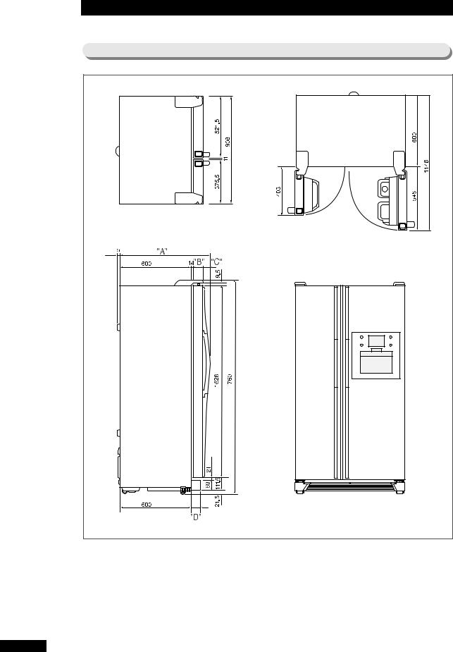
5. Dimension part name of refrigerator
5-1) Product Dimension |
(SR-S2025, S2-YTC) |
|
(SR-S2025, S20YTC |
MODEL |
“A” |
“B” |
|
“C” |
“D” |
|
|
|
|
|
|
SR-S2025C, S20YTC |
719 |
50 |
55 |
|
54 |
|
|
|
|
|
|
SR-S2025D, S20YTC |
714 |
50 |
50 |
|
54 |
|
|
|
|
|
|
9
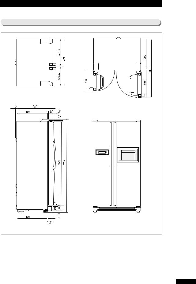
5-2) Product Dimension |
(SR-S2026, S2027, S2226, S2227/S20NTC,S20BTC,S22NTC,S22BTC) |
|
(SR-S2027, S2227) |
|
-S20BTC,S22BTC |
MODEL |
“A” |
“B” |
|
“C” |
“D” |
|
|
|
|
|
|
SR-S2026C, S2027C/S20NTC,S20BTC(D) |
719 |
50 |
55 |
|
54 |
SR-S2026D, S2027D/S20NTC(D),S20BTC(D) |
714 |
50 |
50 |
|
54 |
SR-S2226C, S2227C/S22NTC,S22BTC(D) |
754 |
85 |
55 |
|
89 |
SR-S2226D, S2227D/S22NTC(D),S22BTC(D) |
749 |
85 |
50 |
|
89 |
|
|
|
|
|
|
10
5-3) Product Dimension |
(SR-S2028, S2029, S2228, S2229/S20DTC,S20FTC,S22DTC,S22FTC) |
|
(SR-S2029, S2229) |
|
-S20FTC,S22FTC |
MODEL |
“A” |
“B” |
|
“C” |
“D” |
|
|
|
|
|
|
SR-S2028C, S2029C/S20DTC,S20FTC(D) |
719 |
50 |
55 |
|
54 |
SR-S2028D, S2029D/S20DTC(D),S20FTC(D) |
714 |
50 |
50 |
|
54 |
SR-S2228C, S2229C/S22DTC,S22FTC(D) |
754 |
85 |
55 |
|
89 |
SR-S2228D, S2229D/S22DTC(D),S22FTC(D) |
749 |
85 |
50 |
|
89 |
|
|
|
|
|
|
11
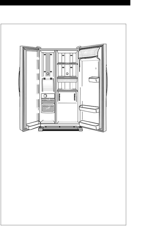
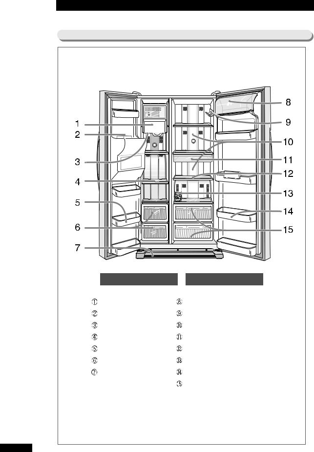
5-4) Part Name (SR-S2025 / SR-S20YTC) |
12
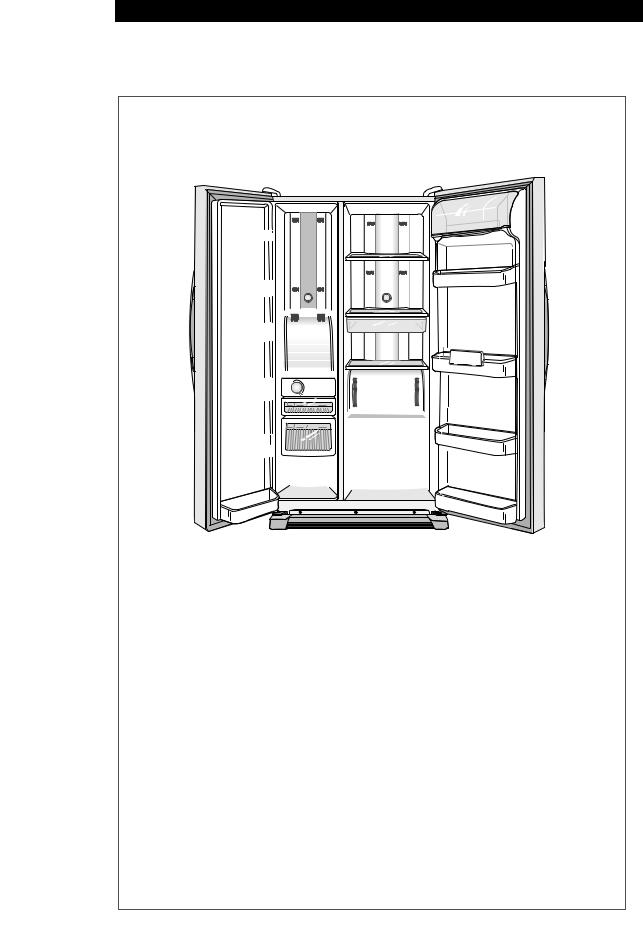
5-5) Part Name (SR-S2026, S2226/S20NTC,S22NTC) |
13
5-6) Part Name (SR-S2027, S2227/S20BTC,S22BTC) |
14
5-7) Part Name (SR-S2028, S2228/S20DTC,S22DTC) |
15
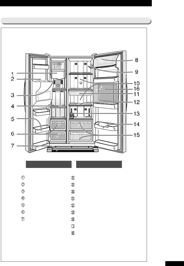
5-8) Part Name (SR-S2029, S2229/S20FTC,S22FTC) |
16
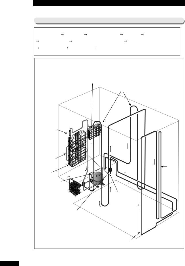
6. Freezing Cycle & Cold Air Circulation Course in Refrigerator
6-1) Freezing Cycle |
|
|
|
|
|
|
COMPRESSOR |
|
WIRE-COND |
SIDE CLUSTER PIPE |
HOT PIPE |
DRYER |
|
CAPILLARY TUBE |
REFRIGERATOR EVAPORATOR |
FREEZER |
EVAPORATOR |
|
||
ACCUMULATOR |
SUCTION PIPE |
|
COMPRESSOR |
|
|
|
|
|
REFRIGERATOR EVAPORATOR |
|
|
|
|
|
|
|
|
|
SIDE CLUSTER PIPE |
|
ACCUMULATOR |
|
|
|
|
|
|
SUCTION PIPE |
|
|
|
|
|
|
|
|
|
|
|
|
HOT-PIPE |
FREEZER |
|
|
|
|
|
|
EVAPORATOR |
|
|
|
|
|
|
COMPRESSOR |
|
|
|
|
|
|
WIRE-CONDENSER |
|
|
|
|
|
|
|
|
|
|
|
CAPILLARY TUBE |
|
|
|
DRYER |
|
|
|
|
|
|
|
|
|
HOT-PIPE |
|
17
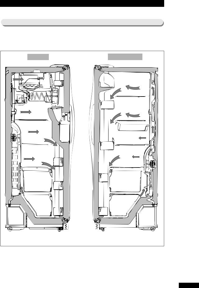
6-2) Cold Air Circulation Course in Refrigerator (Cold Air Passage Circulation Course)
FREEZER |
REFRIGERATOR |
18
7. Function & Operating Instruction of Refrigerator
7-1) Temperature Control Function
1) Basic and with Home Bar Models
2) Dispenser and with Home Bar Models
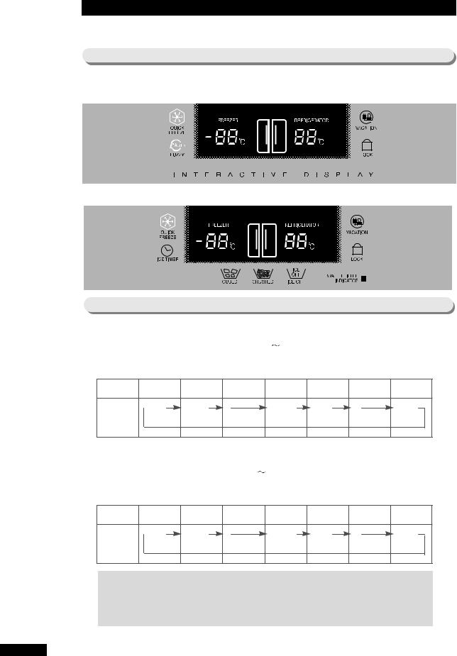
7-2) Temperature Control Function
Temperature selecting function of freezer
1) |
At initial Power On, -20˚C is selected automatically. |
2) |
Select one button for 13 levels of -14˚C -26˚C. |
3) |
1˚C drops per each pressing of temperature selection button of freezer. |
Division |
At Initial Power On |
One Time Press |
● |
● |
● |
6 Times Press |
7 TimesPress |
● |
● |
● |
12 TimesPress |
|
|
|
|
|
|
||||||
Display |
-20˚C |
-21 ˚C |
|
|
|
-26˚C |
-14 ˚C |
|
|
|
-19˚C |
|
|
|
|
|
|
|
|
|
|
|
|
Change |
|
|
|
|
|
|
|
|
|
|
|
Temperature selecting function of Refrigerator |
|
|
1) |
At initial Power On, 3˚C is selected automatically. |
|
2) |
Select one button for 9 levels of 7˚C |
-1˚C. |
3) |
1˚C drops per each pressing of temperature selection button of Refrigerator. |
|
Division |
At Initial Power On |
One Time Press |
● |
● |
● |
4 Times Press |
5 TimesPress |
● |
● |
● |
8 TimesPress |
|
|
|
|
|
|
||||||
Display |
3 ˚C |
2 ˚C |
|
|
|
-1˚C |
7 ˚C |
|
|
|
4 ˚C |
|
|
|
|
|
|
|
|
|
|
|
|
Change |
|
|
|
|
|
|
|
|
|
|
|
Reference (terms explanation)
1)F Room: freezer 2) R Room: Refrigerator 3) F-FAN: fan motor in
freezer 4) R-FAN: fan motor in Refrigerator 5) COMP: compressor
19

Reference
Temperature of table on previous page is temperature of center part of
1/3 height of Refrigerator/Freezer compartments. It is temperature data at unload state. When actually used, temperature may differ according to surrounding condition and use frequency. The table displays general characteristic of temperature.
7-3) Function of Quick Freeze & Vacation
●Select extra Quick Freeze & Vacation button.
●Whenever Quick Freeze & Vacation button is pressed, selection/ cancellation (corresponding lamp On/Off) is repeated.
●When Quick Freeze & Vacation is selected, temperature setup of freezer and Refrigerator does not change.
●At state of selecting Quick Freeze & Vacation, change of temperature setup of freezer and Refrigerator is possible.
Quick Freeze Function
1)When Quick Freeze function is selected, COMP and F-FAN operates continuously for 2 and half hours.
2)While Quick Freeze function is working, Refrigerator operates under present setup condition.
3)When Quick Freeze function is completed (after continuous operation of COMP, F-FAN for 2 and half hours), Quick Freeze lamp lights out automatically and operates according to setup temperature of freezer.
Vacation Function
1)When Vacation is selected, Refrigerator fan is turned off.
2)Though Vacation function is selected, Refrigerator fan does not turned off but turned on for initial 5 minutes.
3)When Vacation function is selected and Ice Timer is set, Vacation function completes automatically when Ice Maker works by Ice Timer function. Then Refrigerator fan operates according to temperature setup of Refrigerator. (explained in detail at Ice Timer function)
4)Vacation function is selected/ canceled by Vacation button. It can be
canceled by temperature control button of Refrigerator while Vacation function
is selected.
5)While Vacation function is working, Vacation lamp is ON, and temperature display of Refrigerator is OFF.
Reference
If Quick Freeze function is selected when freezer temperature is over -10˚C and Refrigerator temperature is over +10˚C like the condition of initial
Power ON, Refrigerator Fan becomes OFF until freezer temperature drops under certain temperature. When freezer temperature becomes
under certain temperature, Refrigerator Fan operates.
20
7-4) Alarm Function
Button Touch Sound (“Ding-Dong” Sound)
1)Input confirmation sound of “Ding-Dong” sounds when each button of Control Panel is pressed.
2)“Ding-Dong” doesn’t sound if more than two keys are pressed at the same time or buttons are wrongly operated.
Door-Open Alarm Sound (“Ding-Dong” Sound)
1)If door of freezer or Refrigerator remains open over 2 minutes, alarm sounds ten times.
2)If door remains open continually afterward, alarm repeats ten times per one minute cycle.
3)Alarm stops immediately when door of freezer or Refrigerator is closed.
Forced Operation & Forced Defrost Alarm Sound (“Beep” Sound)
1)If forced operation or forced defrost is selected, “Beep” sound occurs.
2)If forced operation is selected, alarm sound occurs until automatic cancellation (after 24 hour’s forced operation) or cancellation function is selected.
3)Also in case of forced defrost, alarm sound occurs until defrost is completed (including pause) or cancellation function is selected.
7-5) Defrost Function
At time of initial Power On, defrost function works for both freezer and Refrigerator at the same time, when integrating time of Comp On is over 4 hours.
Afterward defrost cycle is changeable according to use condition or surrounding environment from 6 hrs. to 38 hrs..
After completing the initial defrost, PRE-COOL function works for 20 min. to minimize temperature increase by defrost work. However, PRE-COOL function is determined according to temperature in Refrigerator at the point of defrost time.
If F-room temperature is over -21˚C, PRE-COOL function works for F-room. If F room temperature is below -21˚C, PRE-COOL function does not work.
21

7-6) Test Function
●Test function is for test, process inspection and SVC of PCB and product.
●After selecting test S/W and confirming function of product, turn on power switch again to operate self-inspection function.
●If you press Quick Freezer Key on Display Panel and temperature control Key in R-room for more than 8 seconds, all Displays will be turned off and continue operating in Test Mode. At this moment, if any key is pressed among freezer temperature control key, Refrigerator temperature control key, quick freeze key or vacation key, it operates as the test button.
F-room : Freezer, R room : Refrigerator
Forced Operating Function
1)In the state where display panel was converted into test mode, if test button is selected once, COMP will operate immediately without 5 minute
delay function. Therefore, forced operation is conducted at the very moment of COMP OFF, over load may be caused. Please be careful.
2)If forced operation is selected, freezer and Refrigerator is set to automatic,
and the temperature of freezer is set to |
“-26˚C ”and Refrigerator is set to |
|
“1˚C ”, Comp and F-fan operates |
continuously, and R-fan in Refrigerator is |
|
controlled by |
“1˚C ”setup. |
|
3)Forced operation is valid for 24hrs. That is, if 24hours. pass after selecting forced operation, simultaneous defrost in both Refrigerator and freezer is automatically carried out. And normal operation is carried out by present setup of Refrigerator and freezer.
4)Cancellation of forced operation in the middle of working is possible by turning on Power after turning it off (resetting), or by selecting test cancel mode shown in the item 3 below.
5)When forced operation works, alarm sound will continue until forced
operation is completed. There is no alarm cancel function.
Forced Defrost Function
1)In the state of forced operation, if display panel is converted into test mode and press the test button once more, forced operation is cancelled immediately, and evaporator defrost function of Refrigerator operates.
2)At this time, beep alarm sounds for 3sec. at the point of defrost, and 0.75sec. ON/0.25sec. off sound occurs during forced defrost function
of Refrigerator works.
3)If above defrost function of Refrigerator is maintained, it operates normally after defrost is completed.
4)While forced defrost function of Refrigerator operates, pressing the test
button once more enables simultaneous defrost for both freezer and Refrigerator.
5)At this time, beep alarm also sounds for 3sec. at the point of defrost, and 0.75sec. ON/ 0.25sec. off sound occurs continually until simultaneous defrost of F and R is completed.
Test Cancel Mode
1)In the state of simultaneous defrost of freezer and Refrigerator, if display panel is converted into test mode, and test button is pressed once more, defrost
of both freezer and Refrigeration is cancelled immediately and resumes normal operation .
Reference
It works step by step in test function. It does not change from 1 step (forced operation) to 4 step (test cancel mode) directly. It operates corresponding function only after it goes through the previous step. While
test function works, it is most desirable to turn off main power and then turn it on.
22
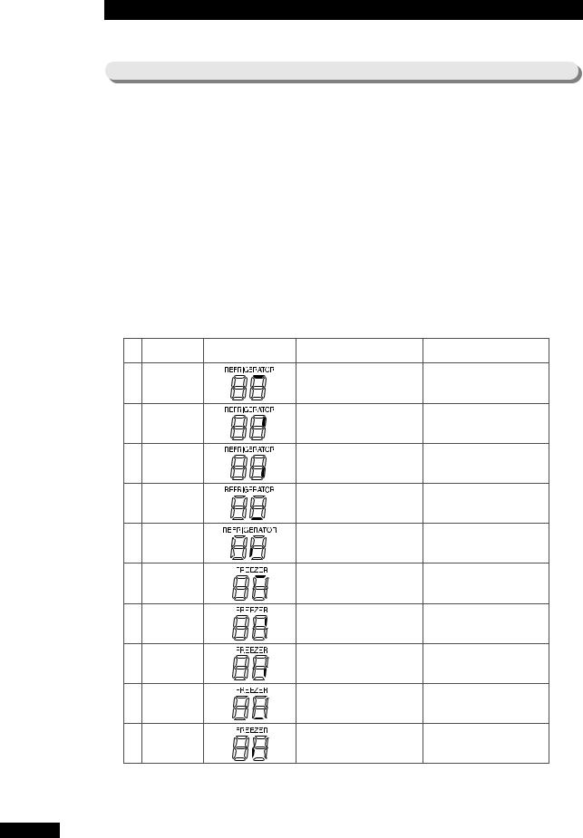
7-7) Self-diagnosis Function
Self-diagnosis Function at the time of initial power is on.
1)When the initial power is applied to Refrigerator, all lamps light and conduct self-diagnosis function internally.
2)If result shows no fault, display will go into the initial normal lighting state.
3)If result shows any fault, corresponding led is turned on and off and alarm sounds.
4)Error sign of self-diagnosis continues until all defects of parts are repaired
or self-checkup function is cancelled.
5)If all corresponding parts are repaired completely, display will go into the normal mode state.
6)After repairing Refrigerator, turn on switch again after turning it off to make it sure if Refrigerator is properly repaired.
7)Therefore, in case open & short related problem of sensor needs to be confirmed during A/S, turn off the power of Refrigerator and turned it on again to operate self-Diagnosis function. Then sensor function can be checked.
8)When any defect occurs, corresponding display signs are shown as in the following chart.
NO |
Items |
Corresponding LED |
Defect Content |
|
|
|
Remark |
|
|
|
|
|
|
|
|
|
|
|
ICE-MAKER |
|
Defect of |
wire connecting system due to |
|
When |
temperature sensing |
of |
R- |
|
|||||||
01 |
|
badness of |
Open/Short related aspect of |
|
|
||||||||||||
|
|
sensor |
is |
more |
than +50 |
|
and |
less |
|||||||||
SENSOR |
|
Sensor which is equipped |
at the |
|
|
||||||||||||
|
|
beneath of ice-making bowl |
|
|
than -50 |
|
. |
|
|
|
|
|
|||||
|
|
|
|
|
|
|
|
|
|
|
|
|
|
|
|||
02 |
Refrigerator |
|
Missing sensor housing of R-room, |
|
Defect is indicated when |
temperature |
|
||||||||||
|
contact defects, disconnection of wires, |
sensing of |
R-sensor is more than |
+50 |
|
||||||||||||
|
R-sensor |
|
defect of short-circuit sensor itself, etc. |
and less than -50 |
. |
|
|||||||||||
|
|
|
|
||||||||||||||
03 |
Refrigerator |
|
Missing sensor housing of R-room, |
|
Defect is indicated when temperature |
|
|
||||||||||
defrost sensor |
|
contact defects, disconnection of wires, |
sensing of R-sensor is more than +50 |
||||||||||||||
|
defect |
of short-circuit sensor itself, etc. |
and less than -50 |
. |
|
|
|
||||||||||
|
|
|
|
|
|
||||||||||||
|
R-fan motor |
|
Interference of Fan due to frost, etc., |
Occurrence of the case where Fan Motor of |
|
||||||||||||
04 |
|
inner refrigerator room becomes to operate |
|
|
|||||||||||||
|
|
un-insertion of connector, |
|
|
|
||||||||||||
Error |
|
|
under about 600rpm at the normal operation |
|
|||||||||||||
|
|
disconnection, etc. |
|
|
condition or stops driving. |
|
|
|
|
||||||||
|
|
|
|
|
|
|
|
|
|
|
|
||||||
05 |
ICE-MAKER |
|
Defect of micro S/W in Gear box, |
|
When normal operation is not done until ice- |
|
|||||||||||
|
motor, gear and other defect in wire |
|
isolating motion |
is attempted |
3 times (only |
|
|||||||||||
|
KIT |
|
system |
|
|
|
|
ice-making function |
model corresponds). |
|
|
|
|||||
|
|
|
|
|
|
|
|
|
|
||||||||
|
Outside Air |
|
Missing |
of outside air sensor housing inside of PCB |
|
Badness is |
indicated |
when temperature sensing |
|
||||||||
06 |
|
base of |
top part of Refrigerator, |
contact defect, |
|
|
|||||||||||
|
|
of |
Outside Air Sensor |
is more than +50 |
|
and |
|||||||||||
|
Sensor |
|
disconnection of wires, defect of |
short-circuit sensor |
|
less |
than -50 |
. |
|
|
|
|
|||||
|
|
|
itself, etc. |
|
|
|
|
|
|
|
|||||||
|
|
|
|
|
|
|
|
|
|
|
|
|
|
|
|
||
07 |
Freezer |
|
Missing sensor housing in |
F-room, |
|
Defect is indicated when temperature |
|
|
|||||||||
|
contact defects, disconnection of wires, |
sensing of F-sensor is more than |
+50 |
|
|||||||||||||
F-sensor |
|
||||||||||||||||
|
|
defect of short-circuit sensor itself, etc. |
and less than -50 |
. |
|
|
|
||||||||||
|
|
|
|
|
|
||||||||||||
08 |
Freezer |
|
Missing |
defrost-sensor housing in evaporator of |
|
Defect |
is indicated when temperature |
|
|||||||||
|
F- room, contact defects, disconnection of |
wires, |
sensing of F-sensor is more than +50 |
|
|||||||||||||
defrost-sensor |
|
||||||||||||||||
|
defect |
of short-circuit sensor itself, etc |
|
and less than -50 |
. |
|
|
|
|||||||||
09 |
F-fan motor |
|
Interference of Fan due to frost, etc., |
Occurrence of the case where Fan Motor of inner freezer |
|
||||||||||||
|
un-insertion of connector, |
|
room becomes to operate under about 600rpm at the |
|
|
||||||||||||
|
Error |
|
disconnection, etc. |
|
|
normal operation condition or stops driving. |
|
|
|
||||||||
10 |
C-fan motor |
|
Un-insertion of connector, |
|
Occurrence of the case where Comp Cooling Fan |
|
|||||||||||
|
|
Motor becomes to operate under about 600rpm at |
|
||||||||||||||
Error |
|
disconnection, etc. |
|
|
|
||||||||||||
|
|
|
the normal operation condition or stops driving. |
|
|||||||||||||
|
|
|
|
|
|
|
|
||||||||||
Note) This self-Diagnosis |
works only when |
the open/short related aspect of sensor is bad. Minute |
|
|
|
|
|
|
|
|
|
|
|||||
|
feature change of sensor is not judged as defect if it does not get rid of the extent |
of temperature |
|
|
|
|
|
|
|
|
|
||||||
|
sensor described in |
Remark so that it is indicated as normal. |
|
|
|
|
|
|
|
|
|
|
|
|
|
||
23
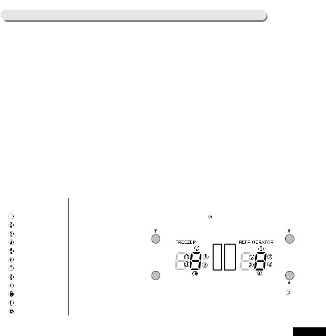
|
|
|
|
|
|
|
|
Self-Diagnosis Function in Normal Operation |
|
|
|
|
|||
1) |
Under normal operation of Refrigerator, if you press |
|
“Quick freeze |
”and |
|||
“Vacation |
”button at the same time for 6sec., temperature setup display |
|
|||||
|
will proceed On/Off blink of all for 2sec. at 0.5sec. interval. |
|
|
||||
|
If you press |
“Quick freeze |
”and |
“Vacation |
”button continuously at the |
|
|
|
same time for about 8sec. including |
2sec. of repetition of LED |
|
’s On/Off, |
|||
|
self-Diagnosis function is selected. |
|
|
|
|
|
|
2) |
At this moment, it goes into self-Diagnosis |
function with |
|
“Ding-dong |
” |
||
|
buzzer sound. |
|
|
|
|
|
|
3) |
When Error occurs, it is restored to normal state regardless of defect |
|
|
||||
|
repairing after signal lasts for 30sec. ( |
“Ding-dong |
”buzzer sound). |
|
|||
4)While it is operating self-Diagnosis function, it does not accept input of button.
7-8) Load Condition Indicating Function
In normal operation, if |
you press |
“Quick freeze |
”and “Vacation |
”button |
at the same time for 6 sec., all setup display of freezer and Refrigerator |
|
|||
are turned on. If you hand off from the button at this moment, temperature |
|
|||
setup display of freezer and Refrigerator will proceed On/Off blink of all for |
|
|||
2sec. at 0.5sec. interval. While On/Off blink is processing, if you press the |
|
|||
temperature setup button, |
it goes |
into load condition indicating function |
|
|
(with ding-dong buzzer sound).
Load condition indicating mode shows from which load Micom signal
outputs at present. However, it only shows that micom signal is outputted and does not confirm whether load is actually operating or not. That is, even if load is displayed as it is operating, load may not operate because of actual defect of load or defect of relay on PCB. During A/S, you can
use this function by applying the main function.
Time required to indicate is 30 sec.. After 30sec., it is automatically restored to the setup state before its function.
Corresponding display indication about load condition is shown as in the following table.
Load Mode Check List
NO |
Display Content |
Operation Content |
|
Press both buttons 6 sec, simultaneously, all LED lights are |
|
|||||||||||
|
|
|
|
|
|
|
turned on and off twice. |
|
|
|
|
|
|
|||
|
R-fan |
high |
|
R-fan high speed operation indication |
|
At this time press button |
. |
|
|
|
|
|
||||
|
R-fan |
low |
|
R-fan low speed operation indication |
|
|
|
|
|
|
|
|
|
|
|
|
|
|
|
|
|
|
|
|
|
|
|
|
|
||||
|
R-Def-Heater |
|
R room defrost-heater operation indication |
|
|
|
|
|
|
|
|
|
|
|
||
|
Start Mode |
|
indication operation stage (Not important) |
|
|
|
|
|
|
|
|
|
|
|
||
|
|
|
|
|
|
|
|
|
|
|
|
|
||||
|
|
|
|
|
|
|
|
|
|
|
|
|
||||
|
|
|
|
|
|
|
|
|
|
|
|
|
|
|
|
|
|
Overload Mode |
|
when |
ambient temperature is more than 34 |
|
|
|
|
|
|
|
|
|
|
|
|
|
|
|
|
|
|
|
|
|
|
|
|
|||||
|
|
|
|
|
|
|
|
|
|
|
|
|
|
|
|
|
|
Low-temperature Mode |
|
when |
ambient temperature is less than 17 |
|
|
|
|
|
|
|
|
|
|
|
|
|
|
|
|
|
|
|
|
|
|
|
|
|
|
|
|
|
|
Comp |
|
|
Comp operation indication |
|
|
|
|
|
|
|
|
|
|
|
|
|
|
|
|
|
|
|
|
|
|
|
|
|
|
|
||
|
F-fan high |
|
F-fan high-speed operation indication |
|
|
|
|
|
|
|
|
|
|
|
||
|
|
|
|
|
|
|
|
|
|
|
|
|
|
|
|
|
|
F-fan low |
|
F-fan low-speed operation indication |
|
|
|
|
|
|
|
|
|
|
|
||
|
|
|
|
|
|
|
|
|
|
|
|
|
||||
|
|
|
|
|
|
|
|
|
|
|
|
|
|
|
|
|
|
F-Def-Heater |
|
F room defrost-heater operation indication |
|
|
|
|
|
|
|
|
|
|
|
||
|
|
|
|
|
|
|
For load under operation, corresponding LED lights on. |
|
||||||||
|
C-fan high |
|
C-fan high-speed rotation operation indication |
|
|
|||||||||||
|
|
|
|
|
|
|
|
|
|
|
|
|
|
|
|
|
|
C-fan |
low |
|
C-fan low-speed rotation operation indication |
|
|
|
|
|
|
|
|
|
|
|
|
24

7-9) Function of Ice/Water Dispenser when they are equipped.
,
25

|
|
|
|
|
|
|
|
|
5) The following are examples for use. |
|
|
|
|
|
|||
In case of selecting vacation function only |
|
|
|
|
||||
If you press |
“vacation |
”button, Refrigerator will not operate and freezer will operate |
|
|||||
only. In case you select this function, take out all foods in the Refrigerator. And |
“Ice |
|||||||
Off ”is automatically selected among ice modes, so ice bucket should be empty and |
|
|||||||
water supply valve should be turned off. |
|
|
|
|
||||
In case of selecting ice timer function only |
|
|
|
|
||||
In case you press |
“Ice Timer |
”button to select date as explained above, and not |
|
|||||
selecting |
“Vacation |
|
”function so that Refrigerator continues to operate, ice mode is |
|
||||
selected as |
“Ice Off |
”and |
ice is stored in the bucket when you return. Therefore, do |
|
||||
not lock the water supply valve. |
|
|
|
|
|
|||
In case of selecting both vacation and ice timer function |
|
|
|
|||||
In case you press |
“Ice Timer |
”button and |
“Ice Timer |
”button to select date to select |
||||
date as explained above, or if you press |
|
“Ice Timer |
”button to select date and press |
|
||||
“Vacation |
”button afterward, Refrigerator does not operate but freezer operates only, |
|
||||||
and ice mode |
is automatically selected |
as |
|
“Ice Off |
”. So you must take out all foods in |
|||
Refrigerator, empty ice in the ice bucket, check water leakage on valves, other hoses |
|
|||||||
and connection parts without locking water supply valve. When |
“Vacation |
”function is |
||||||
cancelled, Refrigerator resumes its operation. |
|
|
|
|||||
Ice Dispenser Function (Cover Ice Route Solenoid Valve)
1)After 8sec. from initial power on, solenoid of ice exit operates once. This is the function to prevent interruption of electric service when ice exit is open. So this is not a defect.
2)With turning the dispenser S/W from on to off and ice ejecting is
completed, 5sec. after turning off S/W, ice exit is closed because cover ice route solenoid of ice dispenser operates.
Water Dispenser Function
1)This function is a system of direct connection with water supply. When water lever is pressed, water solenoid valve which is equipped at the right side of machine room opens so as to operate to eject water. However, it has no function to control on Micom PCB. Therefore, if there happens any defect at water eject function, check and repair solenoid itself, wire connecting connector, connecting tube and state of water supply.
Water Filter Indicator Function
1)After the initial power on, indication lamp is displayed in green light. After 5 months passed, it is displayed in orange light, and 1 month after this, it is displayed in red light. This is memorized by EEPROM in Micom PCB, so it counts the passed time continually though the power is turned on again after it was turned off.
2)If you press ice selecting button and ice-making stop button at the same time for
25sec. continuously, indication lamp lights in green color. And it becomes orange after 5 months from this moment. And it displays red after 1 month from the moment.
3)If you press ice selecting button and ice-making stop button at the same time for 5 sec., indication lamp is turned off and water filter indicator function stops. At this moment, passed time is not counted.
4)At the state where the function is stopped, if you press ice selecting button and ice-
making stop button at the same time for 25sec. continuously, |
“Green |
”light is turned |
on and water filter indicator function will resume. And it becomes orange light after 5 |
|
|
months from this moment. And it displays red light after 1 month from the moment. |
|
|
26

7-10) Restoring Function of Operation State in case of Power Stoppage
27
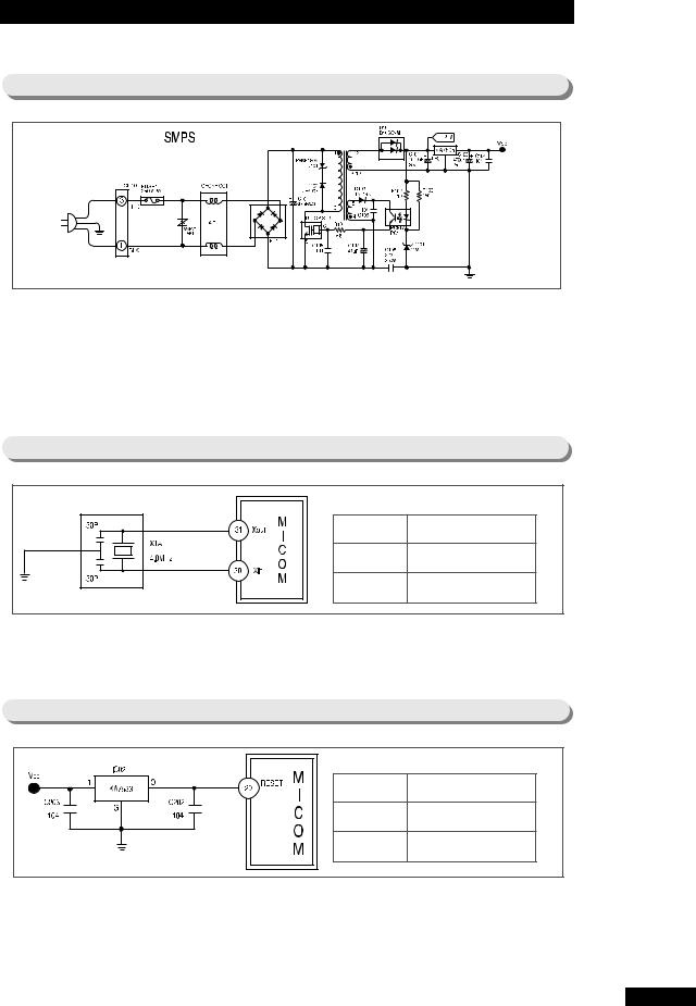
8. Operation Principle of Circuit
8-1) Power Source Part
When power is supplied, electric wave is rectified through BD1 to generate voltage of about DC 300V.Top S/W is automatically switched to the optimum condition according to load condition of the second part.
When electricity flows between D and S of the top S/W, electricity is generated inside the trans, and when the power between D and S is turned off, electricity which is deserted at trans is transmitted to the second part.
This process is repeated to maintain the fixed voltage of 12V by C102 of the second part. This power supplies electricity to power source of 5V, relay and display, and it allows operation of main PCB possible.
8-2) Oscillation Circuit Part
It is oscillation circuit for synchronism clock generation and time calculation on information sending/receiving of internal elements. It does not carry out its normal function because timing system of MICOM alters in case the specification of resonator changes.
8-3) Reset Circuit Part
Terminal |
Voltage |
Vcc |
DC 5V |
RESET |
DC 5V |
Reset circuit is a circuit which allows the whole program operate on an initial position by initializing several parts such as RAM inside of MICOM when power is applied to MICOM. When power is supplied, the reset terminal voltage becomes
several tens “LOW ”state compared with Vcc voltage (DC 5V) of MICOM, and it maintains “HIGH ”(Vcc voltage) state in normal operation condition.
28
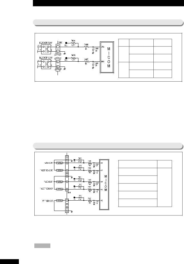
8-4) Door S/W Sensing Circuit
|
Terminal |
Voltage |
|
MICOM |
|
F-Room |
DOOR CLOSE |
5V |
(HIGH) |
|
DOOR OPEN |
0V |
(LOW) |
|
|
|
|||
|
R-Room |
DOOR CLOSE |
0V |
(LOW) |
|
DOOR OPEN |
5V |
(HIGH) |
|
|
|
|||
For door open sensing of F room, |
of CN30 is connected to the ground. For |
|
, Vcc(DC |
|
5V) is supplied through resistance R404(4.7 |
), and“LOW ”(0V)/”HIGH(5V) is applied to |
|||
MICOM by open/close of the F room door so that it can sense open/close of the F room |
|
|
||
door. For door open sensing of R room, |
of CN30 is connected to the ground. For |
|
, |
|
Vcc(DC 5V) is supplied through resistance R403(4.7 |
), and“LOW ”(0V)/”HIGH(5V) is |
|||
applied to MICOM by open/close of the R room door so that it can sense open/close of
the R room door. At this time, if there is any defect at the door S/W, the corresponding fan inside the Refrigerator does not work or alarming function works. Therefore, the door S/W must be checked in case of A/S. That is, if door opens, the corresponding fan inside the Refrigerator stops without fail. When connection point of S/W has defect, MICOM judges that door is open so that it stops the fan though the door is closed.
8-5) Temperature Sensing Circuit Part
MICOM terminal |
Voltage |
PIN #56 (F-SENSOR) |
MICOM |
|
|
PIN #57 (F-DEF-SENSOR) |
terminal |
PIN #58 (R-SENSOR) |
voltage |
changes in |
|
PIN #59 (R-DEF-SENSOR) |
accordance |
with |
|
PIN #60 (EXT-SENSOR) |
temperature. |
|
Sensor uses thermistor which has temperature coefficient of negative resistance. When temperature rises, resistance value gets smaller, and when temperature falls, resistance
value gets larger. R306~R310, C301~C305 are parts for noise prevention, which are not related to temperature sensing characteristic. In case of F-SENSOR, if setup voltage
inputted to MICOM Referred to as Vf, Vf= (Rth*Vcc)/(R303+Rth). Here, Rth is resistance value of thermistor corresponding to temperature. See conversion table of
“Refer 6 ”of this manual on resistance and voltage of sensor about temperature for Reference. As terminal voltage of MICOM corresponding to temperature is also designated, Refer to it at A/S time.
29
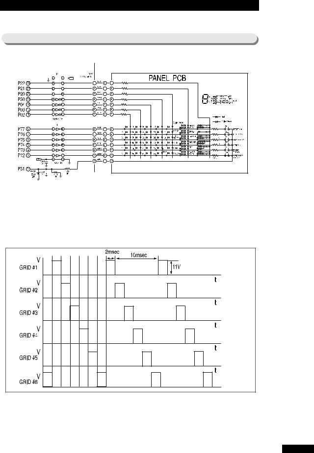
8-6) Key Scan & Display Circuit Part
|
|
|
|
|
|
|
|
|
|
|
|
|
|
|
|
|
|
|
|
|
|
|
|
|
|
|
|
|
|
|
|
|
|
|
|
|
|
|
|
|
|
|
|
|
|
|
|
|
|
|
|
|
|
|
|
|
|
|
|
|
|
|
|
|
|
|
|
|
|
|
|
|
|
|
|
|
|
|
|
|
|
|
|
|
|
|
|
|
|
|
|
|
|
|
|
|
|
|
|
|
|
|
|
|
|
|
|
|
|
|
|
|
|
|
|
|
|
|
|
|
|
|
|
|
|
|
|
|
|
|
|
|
|
|
|
|
|
|
|
|
|
|
|
|
|
|
|
|
|
|
|
|
|
|
|
|
|
|
|
|
|
|
|
|
|
|
|
|
|
|
|
|
|
|
|
|
|
|
|
|
|
|
|
|
|
|
|
|
|
|
|
|
|
|
|
|
|
|
|
|
|
|
|
|
|
|
|
|
|
|
|
|
|
|
|
|
|
|
|
|
|
|
|
|
|
|
|
|
|
|
|
|
|
|
|
|
|
|
|
|
|
|
|
|
|
|
|
|
|
|
|
|
|
|
|
|
|
|
|
|
|
|
|
|
|
|
|
|
|
|
|
|
|
|
|
|
|
|
|
|
|
|
|
|
|
|
|
|
|
|
|
|
|
|
|
|
|
|
|
|
|
|
|
|
|
|
|
|
|
|
|
|
|
|
|
|
|
|
|
|
|
|
|
|
|
|
|
|
|
|
|
|
|
|
|
|
|
|
|
|
|
|
|
|
|
|
|
|
|
|
|
|
|
|
|
|
|
|
|
|
|
|
|
|
|
|
|
|
|
|
|
|
|
|
|
|
|
|
|
|
|
|
|
|
|
|
|
|
|
|
|
|
|
|
|
|
|
|
|
|
|
|
|
|
|
|
|
|
|
|
|
|
|
|
|
|
|
|
|
|
|
|
|
|
|
|
|
|
|
|
|
|
|
|
|
|
|
|
|
|
|
|
|
|
|
|
|
|
|
|
|
|
|
|
|
|
|
|
|
|
|
|
|
|
|
|
|
|
|
|
|
|
|
|
|
|
|
|
|
|
|
|
|
|
|
|
|
|
|
|
|
|
|
|
|
|
|
|
|
|
|
|
|
|
|
|
|
|
|
|
|
|
|
|
|
|
|
|
|
|
|
|
|
|
|
|
|
|
|
|
|
|
|
|
|
|
|
|
Key Scan and Display Operation |
|
|
|
|
|
|
|
|
|
|
|
|
|
|
|
|
|
|
|
|
|
|
|
|
|
|
|
|
|
|
|
|
||||||||||||||||
|
As is seen on each wave form of the following, send |
|
|
“HIGH ”output in an |
|
|
|
|
|
|
||||||||||||||||||||||||||||||||||||||
|
order of MICOM PIN NO #3 |
|
→#4→#5→#6→#7→#8 for 2msec in a cycle |
|
|
|
|
|
|
|||||||||||||||||||||||||||||||||||||||
|
of 12msec using six terminals of MICOM NO #3, 4, 5, 6, 7, |
8. This signal |
|
|
|
|
|
|
||||||||||||||||||||||||||||||||||||||||
|
appears onto output terminal through |
input terminal of IC05(UDN2981 or |
|
|
|
|
|
|
|
|
|
|
|
|
|
|
|
|
||||||||||||||||||||||||||||||
KID65783AP). At this time, peak-to-peak voltage of the spherical wave is about 11V(DC RMS1.5), and form of output wave form is like the drawing 1.
Key Scan
When the wave form of GRID#2 is outputted, this signal is provided to SW6 button
through the resistance of 10 . When SW6 is pressed at this time, signal gets smaller by R501(12 ), and about 4.5V of peak-to-peak voltage is applied to MICOM.
MICOM judges that the wave form of GRID#1 is inputted, and changes function corresponding to SW6 KEY. In this way, each wave form of GRID is recognized.
30
 Loading...