

Samsung SNP-6201, SNP-6201H User Manual

NETWORK CAMERA
User Manual
SNP-6201/SNP-6201H

Network Camera
User Manual
Copyright
©2013 Samsung Techwin Co., Ltd. All rights reserved.
Trademark
The name of thi s product is the reg istered tradema rk of Samsung Techwin C o., Ltd.
Other trad emarks mention ed in this manual are th e registered trad emark of their resp ective company.
Restriction
Samsung Techwi n Co., Ltd shall reser ve the copyrigh t of this document. U nder no circumst ances, this docu ment shall
be reproduced, distributed or changed, partially or wholly, without formal authorization of Samsung Techwin.
Disclaimer
Samsung Techwi n makes the best to ver ify the integri ty and correct ness of the conten ts in this document , but no
formal guar antee shall be provi ded. Use of this do cument and the subse quent results sha ll be entirely on the u ser’s own
responsib ility. Samsung Techwi n reserves the ri ght to change the con tents of this docum ent without prio r notice.
Design and specifications are subject to change without prior notice.
The defau lt password c an be exposed to a h acking thread s o it is recommen ded to change th e password
after in stalling the pr oduct.
Note that t he security a nd other relat ed issues caus ed by the unchan ged password s hall be respon sible
for the use r.
is the regist ered logo of Samsun g Techwin Co., Ltd.

overview
IMPORTANT SAFETY INSTRUCTIONS
1. Read these instructions.
2. Keep these instructions.
3. Heed all warnings.
4. Follow all instructions.
5. Do not use this apparatus near water.
6. Clean only with dry cloth.
7. Do not block any ventilation openings, Install in accordance with the manufacturer’s
instructions.
8. Do not install near any heat sources such as radiators, heat registers, stoves, or other
apparatus (including amplifiers) that produce heat.
9. Do not defeat the safety purpose of the polarized or grounding-type plug. A polarized
plug has two blades with one wider than the other. A grounding type plug has two
blades and a third grounding prong. The wide blade or the third prong are provided for
your safety. If the provided plug does not fit into your outlet, consult an electrician for
replacement of the obsolete outlet.
10. Protect the power cord from being walked on or pinched particularly at plugs,
convenience receptacles, and the point where they exit from the apparatus.
11. Only use attachments/ accessories specified by the manufacturer.
12. Use only with the cart, stand, tripod, bracket, or table specified by
the manufacturer, or sold with the apparatus. When a cart is used,
use caution when moving the cart/apparatus combination to avoid
injury from tip-over.
13. Unplug this apparatus during lighting storms or when unused for
long periods of time.
14. Refer all servicing to qualified service personnel. Servicing is required when the
apparatus has been damaged in any way, such as power-supply cord or plug is
damaged, liquid has been spilled or objects have fallen into the apparatus, the apparatus
has been exposed to rain or moisture, does not operate normally, or has been dropped.
● OVERVIEW
English _3
overview
WARNING
TO REDUCE THE RISK OF FIRE OR ELECTRIC SHOCK, DO NOT EXPOSE
THIS PRODUCT TO RAIN OR MOISTURE. DO NOT INSERT ANY METALLIC
OBJECT THROUGH THE VENTILATION GRILLS OR OTHER OPENNINGS
ON THE EQUIPMENT.
Apparatus shall not be exposed to dripping or splashing and that no objects
filled with liquids, such as vases, shall be placed on the apparatus.
To prevent injury, this apparatus must be securely attached to the Wall/ceiling
in accordance with the installation instructions.
CAUTION
CAUTION
RISK OF ELECTRIC SHOCK.
DO NOT OPEN
CAUTION
REFER SERVICING TO QUALIFIED SERVICE PERSONNEL.
: TO REDUCE THE RISK OF ELECTRIC SHOCK.
DO NOT REMOVE COVER (OR BACK).
NO USER SERVICEABLE PARTS INSIDE.
EXPLANATION OF GRAPHICAL SYMBOLS
The lightning flash with arrowhead symbol, within an
equilateral triangle, is intended to alert the user to the
presence of “dangerous voltage” within the product’s
enclosure that may be of sufficient magnitude to constitute a
risk of electric shock to persons.
The exclamation point within an equilateral triangle is intended
to alert the user to the presence of important operating
and maintenance (servicing) instructions in the literature
accompanying the product.
4_ overview

Battery
Batteries(battery pack or batteries installed) shall not be exposed to excessive
heat such as sunshine, fire or the like.
CAUTION
Risk of explosion if battery is replaced by an incorrect type.
Dispose of used batteries according to the instructions.
These servicing instructions are for use by qualified service personnel only.
To reduce the risk of electric shock do not perform any servicing other than
that contained in the operating instructions unless you are qualified to do so.
The CVBS out terminal of the product is provided for easier installation, and is
not recommended for monitoring purposes.
Please use the input power with just one camera and other devices must not
be connected.
The ITE is to be connected only to PoE networks without routing to the
outside plant.
● OVERVIEW
English _5

overview
Please read the following recommend safety precautions carefully.
yDo not place this apparatus on an uneven surface.
yDo not place this apparatus near conductive material.
yDo not attempt to service this apparatus yourself.
yDo not install near any magnetic sources.
yDo not block any ventilation openings.
yDo not place heavy items on the product.
yDo not expose the camera to radioactivity.
User’s Manual is a guidance book for how to use the products.
The meaning of the symbols are shown below.
yReference : In case of providing information for helping of product’s usages
yNotice : If there’s any possibility to occur any damages for the goods and
human caused by not following the instruction
Please read this manual for the safety before using of goods and keep it in
the safe place.
6_ overview

CONTENTS
OVERVIEW
3
INSTALLATION &
CONNECTION
20
NETWORK CONNECTION
AND SETUP
37
3 Important Safety Instructions
9 Product Features
10 Recomended PC Specifications
10 Recomended SD/SDHC Memory
Card Specifications
11 What’s Included
13 At a Glance (SNP-6201)
16 At a Glance (SNP-6201H)
21 Connecting with other Device
24 Installation
35 Inserting/Removing a SD Memory
Card
36 Memory Card Information (Not
Included)
37 Connecting the Camera Directly
to Local Area Networking
38 Connecting the Camera Directly
to a DHCP Based DSL/Cable
Modem
39 Connecting the Camera Directly
to a PPPoE Modem
40 Connecting the Camera to a
Broadband Router with the
PPPoE/Cable Modem
41 Buttons used in IP Installer
42 Static IP Setup
46 Dynamic IP Setup
47 Port Range Forward (Port
Mapping) Setup
49 Connecting to the Camera from a
Shared Local PC
49 Connecting to the Camera from a
Remote PC via the Internet
● OVERVIEW
English _7

overview
WEB VIEWER
50
SETUP SCREEN
64
APPENDIX
114
50 Connecting to the Camera
51 Login
52 Installing ActiveX
53 Installing Silverlight Runtime
55 Using the Live Screen
59 Playing the recorded video
64 Setup
64 Audio & Video Setup
85 Network Setup
94 Event Setup
108 System Setup
114 DIP Switch Setting
124 Camera Wiring
125 Specification
130 Product Overview
132 Troubleshooting
134 Open source license notification
on the product
8_ overview

PRODUCT FEATURES
• Full HD Video Quality
• Multi-Streaming
This network camera can display videos in different resolutions and qualities
simultaneously using different CODECs.
• Web Browser-based Monitoring
Using the Internet web browser to display the image in a local network environment.
• Alarm
If an event occurs, the event-related video will be transferred to the FTP/email specified
by the user or saved to the SD memory, or the event signal will be sent to the Alarm Out
port.
• Tampering Detection
Detects tempering attempts on video monitoring.
• Motion Detection
Detects motion from the camera’s video input.
• Intelligent Video Analysis
Analyzes video to detect logical events of specified conditions from the camera’s video
input.
• Face Detection
Detects faces from the camera’s video input.
• Audio Detection
Detects sound louder than a certain level specified by user.
• Auto Detection of Disconnected Network
Detects network disconnection before triggering an event.
• ONVIF Compliance
This product supports ONVIF Profile-S.
For more information, refer to www.onvif.org.
● OVERVIEW
English _9

overview
RECOMENDED PC SPECIFICATIONS
• CPU : Intel Core 2 Duo 2.6GHz or higher
• Resolution : 1280X1024 pixels or higher
• RAM : 2GB or higher
• Supported OS : Windows XP / VISTA / 7, MAC OS X 10.7
• Supported Browser : Microsoft Internet Explorer (Ver. 10 ~ 7)
Mozilla Firefox (Ver. 19 ~9) ※ Windows Only
Google Chrome (Ver. 25 ~ 15) ※ Windows Only
Apple Safari (Ver. 6.0.2(Mac OS X 10.8, 10.7 only), 5.1.7) ※ Mac OS X only
Neither a beta test version unlike the version released in the company website nor the developer version will
`
be supported.
It is recommended to connect to IPv6 in Windows 7.
`
For Mac OS X, only the Safari browser is supported.
`
• Video Memory : 256MB or higher
If the driver of the video graphic adapter is not installed properly or is not the latest version, the
`
J
video may not be played properly.
For a multi-monitoring system involving at least 2 monitors, the playback performance can be
`
deteriorated depending on the system.
It is advisable to use Intel Core 2 Duo 2.93GHz or higher in a multi-browser environment.
`
RECOMENDED SD/SDHC MEMORY CARD SPECIFICATIONS
• 4GB ~ 32GB
• For your camera, we recommend you use a memory card from the following
manufacturers:
SD/SDHC Memory Card : Sandisk, Transcend
• It is recommended to use memory cards of at least class 6 speed.
10_ overview
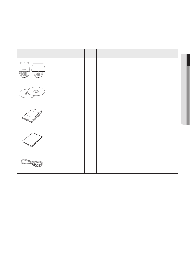
WHAT’S INCLUDED
Please check if your camera and accessories are all included in the product package.
Appearance Item Name
Camera 1
Instruction book,
Installer S/W CD,
CMS S/W DVD
Quantity
2
Description Model Name
● OVERVIEW
Quick Guide
(Optional)
Warranty card
(Optional)
Cable for the testing
monitor
1
1
Used to test the camera
1
connection to a portable display
device
SNP-6201 or
SNP-6201H
English _11
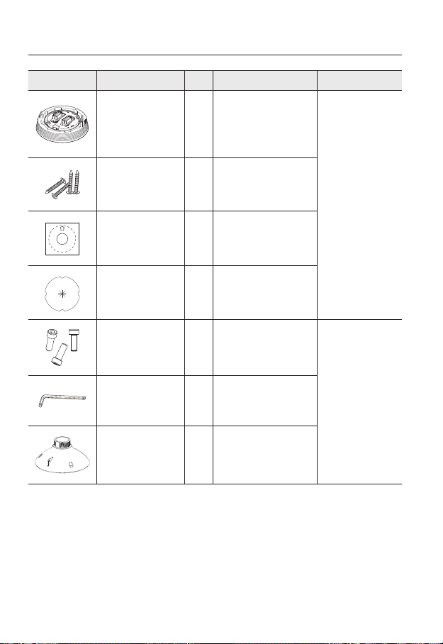
overview
Appearance Item Name
Installation base 1
Tapping Screw 4
Template 1 Product installation guide
Insulation Sheet 1
Hexagon screw 3
L Wrench 1
Installation base 1 Bracket for mounting outdoors
Quantity
Description Model Name
If installing it indoors or in a
ceiling housing
Used for installation on the
ceiling
Use when installing the camera
at highly humid place
Used for attaching the
installation base to the camera
Used for fixing the installation
base after attaching it to the
camera
SNP-6201
SNP-6201H
12_ overview
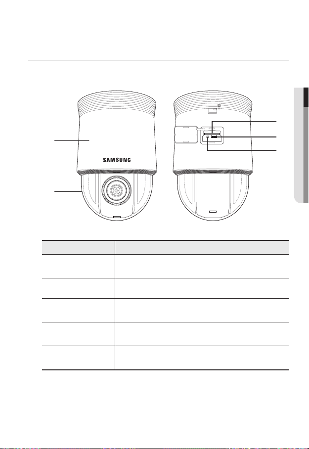
AT A GLANCE (SNP-6201)
Appearance
a
b
Item Description
Main unit
a
Dome Cover Dome cover for the lens and unit protection.
b
SD Memory Card
c
Compartment
After Service Port
d
(A/S port)
Reset Button
e
Protects the internal PTZ mechanism from the direct sunlight or external
impact.
Compartment for the SD memory card.
This is for the repair purpose only that is not available for the user.
Pressing and holding this button for about 5 seconds will reset all camera
settings to the factory default.
● OVERVIEW
c
d
e
English _13
overview
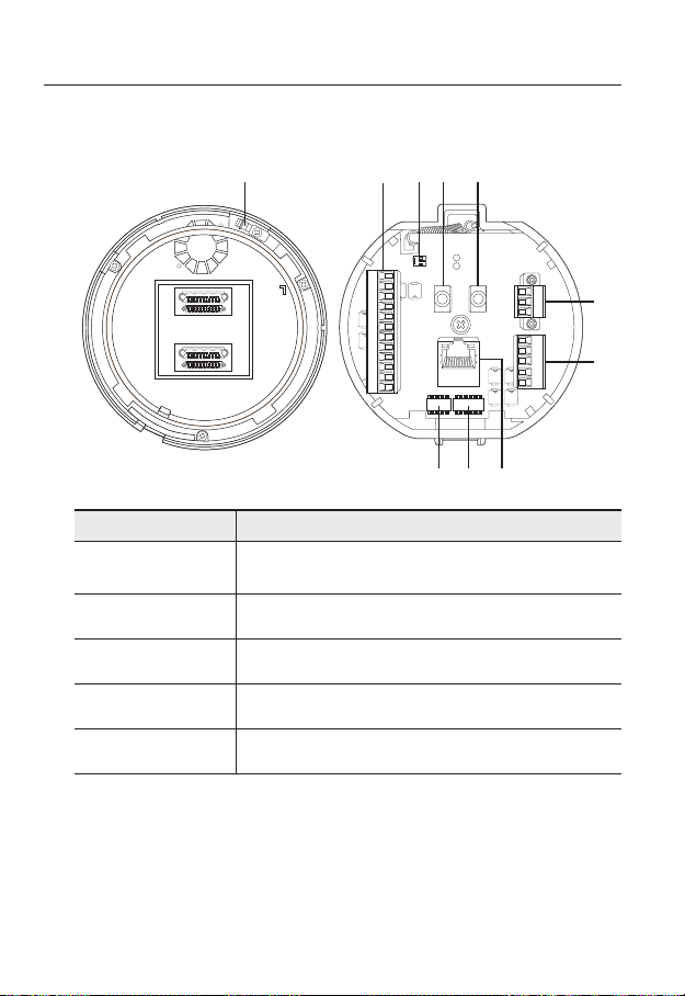
Bottom View of Installation
Base
a
Item Description
Safety Cable
a
Connection Ring
Alarm I/O Port Used to connect the alarm I/O cable.
b
Video Out Port Analog video output port. (for installation)
c
Audio Input Port Used to connect the audio input cable.
d
Audio Output Port Used to connect the audio output cable.
e
Connect the cable to prevent the product from dropping during installation to
the ring.
Inner View of Installation Base
b c e
d
AUDIO OUT
AUDIO IN
GND
1.COM
1.NO 1.NCIN1 IN2 GND IN3 IN4
2.COM
2.NO
2.NC
h
i j
AC- FG AC-
IN5 IN6 GNDIN7 IN8
f
g
14_ overview

Item Description
Power Port Used to connect the power.
f
Communications
g
Ports
ID Setup Switch Specify the camera ID.
h
Communications
i
Setup Switch
Network
j
Connections
Used for RS-485/422 communications.
Set the transfer rate and protocols.
You can use a PoE+ or an Ethernet cable to connect this terminal to the
network.
● OVERVIEW
English _15
overview
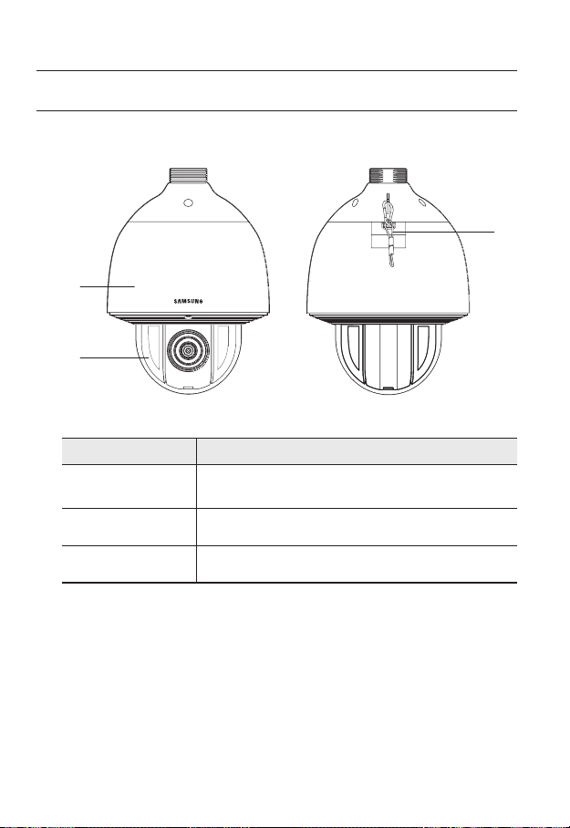
AT A GLANCE (SNP-6201H)
Appearance
a
b
Item Description
Main unit
a
Dome Cover Dome cover for the lens and unit protection.
b
Safety Cable The cable prevents the product from dropping during installation.
c
Protects the internal PTZ mechanism from the direct sunlight, rain or
external impact.
c
16_ overview
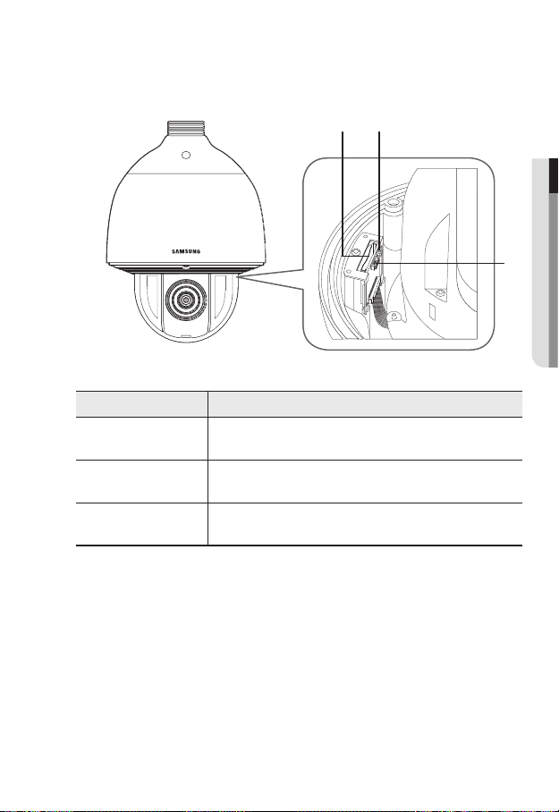
Inside
a
b
c
a
Item Description
SD Memory Card
Compartment
Reset Button
After Service Port
(A/S port)
Compartment for the SD memory card.
Pressing and holding this button for about 5 seconds will reset all camera
settings to the factory default.
This is for the repair purpose only that is not available for the user.
b
● OVERVIEW
c
English _17
overview
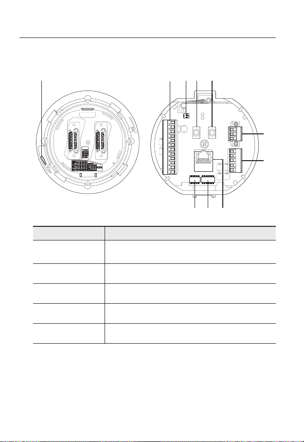
Bottom View of Installation
Base
a
Item Description
Safety Cable
a
Connection Ring
Alarm I/O Port Used to connect the alarm I/O cable.
b
Video Out Port Analog video output port. (for installation)
c
Audio Input Port Used to connect the audio input cable.
d
Audio Output Port Used to connect the audio output cable.
e
Connect the cable to prevent the product from dropping during installation to
the ring.
Inner View of Installation Base
b c e
d
AUDIO OUT
AUDIO IN
GND
1.COM
1.NO 1.NCIN1 IN2 GND IN3 IN4
2.COM
2.NO
2.NC
h
i j
AC- FG AC-
IN5 IN6 GNDIN7 IN8
f
g
18_ overview

Item Description
Power Port Used to connect the power.
f
Communications
g
Ports
ID Setup Switch Specify the camera ID.
h
Communications
i
Setup Switch
Network
j
Connections
Used for RS-485/422 communications.
Set the transfer rate and protocols.
You can use a PoE+ or an Ethernet cable to connect this terminal to the
network.
● OVERVIEW
English _19
installation & connection
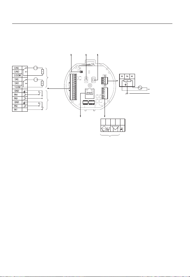
`Camera Wiring Interface Board
For the camera wiring, please refer to the picture below.
Audio
Alarm
Alarm
output
Alarm Input
Video
Output
GND
1.COM
1.NO 1.NCIN1 IN2 GND IN3 IN4
2.COM
2.NO
2.NC
Audio
IN
OUT
Power Supply
AC- FG AC-
AUDIO OUT
AUDIO IN
IN5 IN6 GND IN7 IN8
AC24V 2.5A
Power Input
Ground
Select Normal Open in the setup menu.
`
J
The sensor input is activated during a short for contact type, or when it is at “Low” level for
-
the active type.
Select Normal Close from the Setup menu.
`
The sensor input is activated when open for the contact type or when in high impedance
-
state (open collector) for the active type.
The maximum power capacity of the alarm outputs is DC +40V and 80 mA.
`
When connecting alarm input and output cables, be sure to connect one cable to each
`
terminal respectively.
To connect products over the camera’s capacity, please use an additional relay device.
`
Connecting the power connector and GND incorrectly to the alarm out port may lead to fire
`
and damage the camera.
20_ installation & connection
ETHERNET
Communications
D+ D- TX+ TX- GND
Refer to Control Signal
Connection Diagram
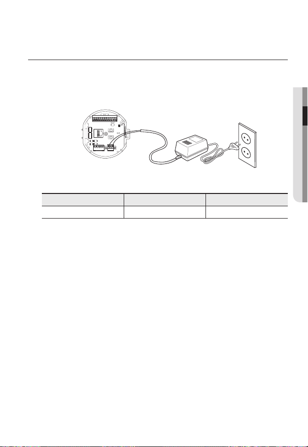
CONNECTING WITH OTHER DEVICE
Preparing Adapter and Cable
Connect the camera to the power adaptor. Then, plug the power cord of the adaptor to the wall
`
J
outlet.
GND
1.COM
1.NO 1.NCIN1 IN2 GND IN3 IN4
2.COM
2.NO
2.NC
AUDIO IN
AUDIO OUT
AC- FG AC-
IN5 IN6GND IN7 IN8
Check out the rated voltage and current before making connections.
Rated Power Allowable Input Voltage Current Consumption
AC 24V AC 22V ~ 26V 2.5 A
If applied with both PoE+ and AC 24V power supplies, the device is powered from the first
`
J
engaged supply.
It is preferred to use single power supply of either one of PoE+ and AC 24V.
-
If connected to a switch device that provides PoE+ power, you don’t need to apply a power source
`
of AC 24V supply.
Make sure the PoE device suffices PoE+ (IEEE 802.3at) specifications.
`
If your device is connected to the switch with the standard of PoE (IEEE 802.3af), then go to
-
the switch setup menu to “deactivate PoE”.
For further information on switch device, refer to the manufacturer’s manual.
If you use a PoE+ as a power, the boot time may vary depending on a switch model (by channel)
`
or a maker (as PoE+ connection time is included.).
● INSTALLATION & CONNECTION
English _21

installation & connection
Electrical Resistance of Copper Wire at [20°C (68°F)]
Copper Wire Gauge (AWG) #24(0.22mm2) #22(0.33mm2) #20(0.52mm2) #18(0.83mm2)
Resistance (Ω/m) 0.078 0.050 0.030 0.018
Drop Voltage (V/m) 0.028 0.018 0.011 0.006
Recommended Distance (m) Less than 20 Less than 30 Less than 30 Less than 30
As shown in the table above, you may encounter a voltage-sag depending on the wire length.
`
If you use an excessively long wire for camera connection, the camera may not work properly.
Camera Operating Voltage: AC 24V±10%
-
Voltage drop measurements on the chart above may vary depending on the type and manufacture of
-
the copper cable.
Ethernet Connection
Connect the Ethernet cable to the local network or to the Internet.
22_ installation & connection
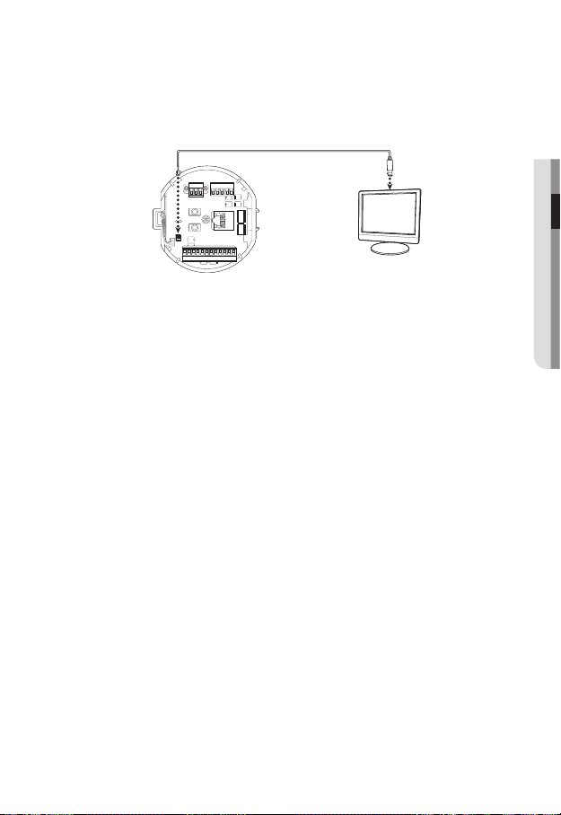
Connecting the installation monitor
Connect the cable to the camera’s rear video output terminal and the installation monitor’s
video input terminal.
IN5 IN6 GNDIN7 IN8
AC- FG AC-
AUDIO OUT
AUDIO IN
GND
1.COM
1.NO 1.NCIN1 IN2 GND IN3 IN4
2.COM
2.NO
2.NC
The wiring varies depending on your monitor type and peripheral devices; please refer to the user manual
`
for each device.
Please make sure the monitor and camera are turned off when connecting them.
`
This product is a network camera that transfers video over a network; the video output terminal is
`
J
used to set the imaging range of the camera at installation.
Using the terminal for monitoring purposes may cause problems such as degradation in video
`
quality.
It is not suitable for 24-hour monitoring using professional CRT monitors or TFT/LCD portable
`
monitors.
Use the network transfer screen for 24-hour monitoring and storage.
`
Monitor
● INSTALLATION & CONNECTION
English _23

installation & connection
INSTALLATION
Preparing & Installing Camera Bracket
For installation guidelines for brackets and housings, refer to the installation manual that is
enclosed with the bracket or housing.
`Available Bracket Models
Model Item SNP-6201 SNP-6201H
SHP-3701H Outdoor Housing
-SHP-3701F Ceiling-mount Housing
SBP-300HM3 Hanging Mount
SBP-300WM1
SBP-300WM
SBP-300CM Ceiling Mount
SBP-300LM Parapet Mount
SBP-300KM Corner Mount
SBP-300PM Pole Mount
See “Optional Accessories for Installation” for the appearance of each bracket (unbundled).
`
M
(page 31)
Wall Mount
Yes
Yes
24_ installation & connection
Installing by surface attachment
SNP-6201H cannot be installed on the surface of a wall or ceiling.
`
M
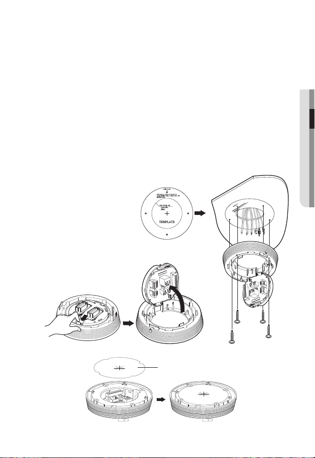
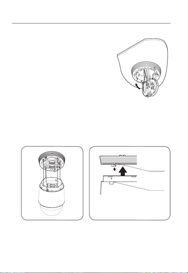
`Attaching Template & Installing installation base
1. Attach the provided template on the ceiling. Based on the template, drill a 86mm
hole in the ceiling and arrange the wires through the hole.
2. Install installation base as shown.
3. Before installing the exposed bracket, open the hinged door at the bottom of the
bracket as shown in the picture. Hold the knob on the hinged door to open it.
In the case of installing the camera at highly humid place, install it on the ceiling after attaching
`
J
the enclosed insulation sheet on the back of install base.
Template
● INSTALLATION & CONNECTION
Insulation Sheet
<Attaching insulatioin sheet>
English _25
installation & connection
`Connect Terminal Wires
1. Connect the cables to the terminal block on the
hinged door. Refer to “Camera Wiring Interface
Board”. (page 20)
2. Once the wiring is complete, close the hinged
door.
Do not connect the camera to a power outlet until the
`
J
installation is complete. Supplying power while the
installation is in progress may cause fire or damage the
product.
`Connecting Camera Safety Cable and Attaching Camera
1. First, as shown in the left hand picture, pull out the safety cable from the base and
then hook it to the mount. The safety cable is coiled inside the base.
To attach the camera to the mount, refer to the alignment guide marks as shown in the picture.
`
2. Carefully attach the camera to the mount following the alignment guide marks as
shown in the picture.
Direction
Guides
Direction
Guides
Make sure to hook the camera’s safety cable to the mount before proceeding. Otherwise you may
`
J
be exposed to serious injury caused by the camera falling.
26_ installation & connection
Align the Direction
Guides
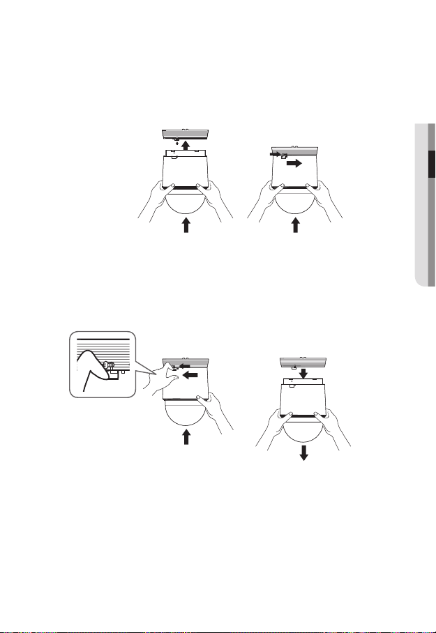
- To attach or detach the camera, refer to the picture.
• Attaching the Camera : Push up the camera unit and rotate it clockwise until
it cannot be rotated anymore, as shown in the figure. After rotation, fasten the
screws assembled to the install base.
< To Attach the Camera >
• Detaching the Camera : Unfasten the screws as shown in the figure, push in the
hook, and rotate it counterclockwise.
(The screws are not completely disassembled.)
When the hook does not rotate any more, pull down the camera unit and
separate it.
< To Detach the Camera >
● INSTALLATION & CONNECTION
English _27
installation & connection
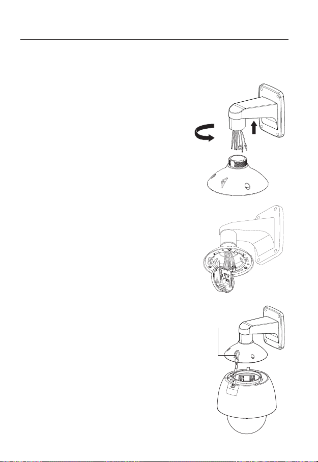
Installing by wall mount
`Fix the installation base with the bracket
1. Fix the base with the bracket by turning it
clockwise.
2. As shown in the picture below, gently press and lift
up the handle of the hinged door on the bottom of
the installation base. Please refer to the “Camera
Wiring Interface Board” on page 20, connect the
wires.
Do not connect the camera to a power outlet until the
`
J
installation is complete. Supplying power while the
installation is in progress may cause fire or damage the
product.
3. Connect the camera safety wire to the installation base.
Safety Cable
28_ installation & connection
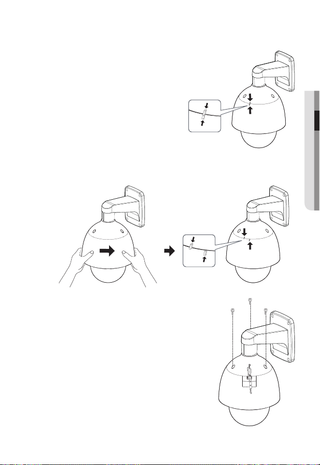
4. Assemble Camera and Installation Base
Assemble the installation base and camera
by matching the installation direction guides.
5. Attach Camera
Rotate the mounted camera unit clockwise so that the reference indicators of top
and bottom are as shown in the image on the right.
6. Secure Camera and Installation Base
As shown in the picture below, secure
the installation base and camera using 3
hexagon screws.
● INSTALLATION & CONNECTION
English _29
installation & connection
Notes for Waterproofing
This product is an indoor unit. If it is installed outdoors, use the outdoor housing to make it
waterproof.
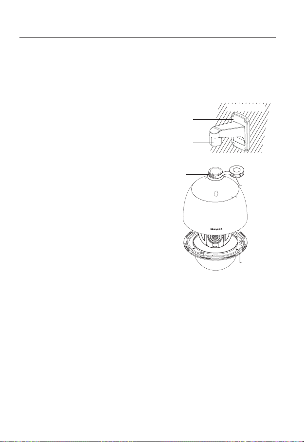
`Installing the unit on the wall by combining the outdoor housing and wall
mount
1. Install the wall mount on the vertical wall.
If the mount is installed on an inclined
wall, moisture can penetrate inside the
outdoor housing through the external
cable.
2. Wrap the screw part of the housing with
a sufficient amount of Teflon tape for
assembly.
3. When separating the dome cover and
fastening it to the housing frame, make
sure that the gasket is not loosened to
separate from the dome cover.
4. Install the wall mount adapter for
waterproofing, and apply the silicon
sealant between and around the wall and
wall mount for sealing.
Take particular caution to ensure that there
`
J
is proper sealing if the installed side is not
flat.
Silicon
sealant
Wall mount
Screw
unit
Concrete wall
Teflon tape
Dome gasket
30_ installation & connection
 Loading...