


REFRIGERATOR
RB195BSSW
RB195BSSB
RB195BSVQ
RB195BSBB
RB215BSSW
RB215BSSB
RB215BSVQ
RB215BSBB
REFRIGERATOR |
|
PRODUCT FEATURE |
|
|
|
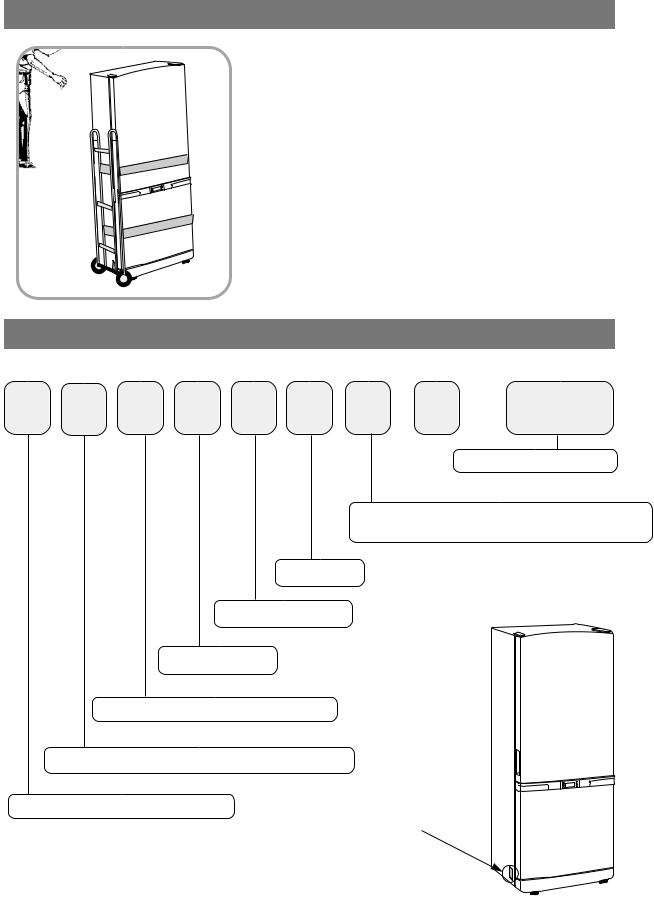
● Reversible Door
● Auto Ice-Maker
● Fridge Wire Box

 WARNING
IMPORTANT SAFETY NOTICE
The service guide is for service men with adequate backgrounds of electrical, electronic, and mechanical experience. Any attempt to repair a major appliance may result in personal injury and property damage. The manufacturer or dealer cannot be responsible for the interpretation of this information.
SAMSUNG ELECTRONICS AMERICA, INC.
Technical Service Guide
Copyright 2005
All rights reserved. This service guide may not be reproduced in whole or in part in any form without written permission from the SAMSUNG ELECTRONICS Company.
2

Contents
1.INSTALLATION ∙∙∙∙∙∙∙∙∙∙∙∙∙∙∙∙∙∙∙∙∙∙∙∙∙∙∙∙∙∙∙∙∙∙∙ 4
2.NOMENCLATURE∙∙∙∙∙∙∙∙∙∙∙∙∙∙∙∙∙∙∙∙∙∙∙∙∙∙∙∙∙∙∙∙∙∙4
3.PRODUCT SPECIFICATIONS∙∙∙∙∙∙∙∙∙∙∙∙∙∙∙∙∙∙∙∙∙∙∙∙∙∙∙5
4.ELECTRICAL PART SPECIFICATIONS & STANDARD∙∙∙∙∙∙∙∙∙∙∙∙∙5
5.WARRANTY INFORMATION ∙∙∙∙∙∙∙∙∙∙∙∙∙∙∙∙∙∙∙∙∙∙∙∙∙∙∙7
6.INTERIOR VIEWS AND DIMENSIONS∙∙∙∙∙∙∙∙∙∙∙∙∙∙∙∙∙∙∙∙∙∙8
7.REFRIGERATION CYCLE AND COOL AIR CIRCULATION ROUTE ∙∙∙∙10
8.MECHANICAL DISASSEMBLY ∙∙∙∙∙∙∙∙∙∙∙∙∙∙∙∙∙∙∙∙∙∙∙∙∙∙12
9.REVERSIBLE THE DOOR SWING∙∙∙∙∙∙∙∙∙∙∙∙∙∙∙∙∙∙∙∙∙∙∙∙19
10.INSTALLATION OF THE WATER LINE ∙∙∙∙∙∙∙∙∙∙∙∙∙∙∙∙∙∙∙∙∙24
11.TEMP CONTROL &OPERATION FUNCTIONS ∙∙∙∙∙∙∙∙∙∙∙∙∙∙∙∙25
12.OPERATION PRINCIPLES BY PARTS OF CIRCUIT∙∙∙∙∙∙∙∙∙∙∙∙∙46
13.DIAGNOSTICS ∙∙∙∙∙∙∙∙∙∙∙∙∙∙∙∙∙∙∙∙∙∙∙∙∙∙∙∙∙∙∙∙∙∙54
15.OTHER ∙∙∙∙∙∙∙∙∙∙∙∙∙∙∙∙∙∙∙∙∙∙∙∙∙∙∙∙∙∙∙∙∙∙∙∙∙∙∙72
16.PCB DIAGRAM ∙∙∙∙∙∙∙∙∙∙∙∙∙∙∙∙∙∙∙∙∙∙∙∙∙∙∙∙∙∙∙∙∙∙75
17.CONNECTOR ARRANGEMENT&DESCRIPTIONS ∙∙∙∙∙∙∙∙∙∙∙∙∙76
18.BLOCK DIAGRAM ∙∙∙∙∙∙∙∙∙∙∙∙∙∙∙∙∙∙∙∙∙∙∙∙∙∙∙∙∙∙∙∙77
19.CIRCUIT DIAGRAM ∙∙∙∙∙∙∙∙∙∙∙∙∙∙∙∙∙∙∙∙∙∙∙∙∙∙∙∙∙∙∙78
20.WIRING SCHEMATIC ∙∙∙∙∙∙∙∙∙∙∙∙∙∙∙∙∙∙∙∙∙∙∙∙∙∙∙∙∙∙79
21.TEMP TO RESISTANCE OF SENSOR &MICOM PORT VOLTAGE ∙∙∙∙80
3
1. INSTALLATION
1) To protect refrigerator in movement
Use padded hand truck from side only.
2)Remove all protective tape and pad from the refrigerators.
Connect power cord. Adjust the clearance between the doors.
3)Temperature controls and preset in the factory for
recommended settings.
The refrigerator should runs smoothly and lower the temperature gradually.
4) Once the refrigerator temperature is sufficiently low
It is recommended to store foods in the refrigerator. It takes a few hours to reach the preset temperatures.
2. NOMENCLATURE
2005 Models
R B 19 5 B S SB / |
XAA |
|
Company Name |
COLOR ; SB-STAINLESS PLATINUM, SW-SNOW WHITE |
|
VQ-BISQUE GLOSSY, BB-BLACK |
|
S : W2-PJT
Buyer : BEST BUY
OPTION ; BETTER
Capacity ; 19:19CU,FT 21:21CU,FT
B - BOTTOM MOUNTED FREEZER (BMF)
Product ; R - REFRIGERATOR
Label Location
4

3. PRODUCT SPECIFICATIONS
Model |
RB195BSSW, RB195BSSB, RB195BSVQ, RB195BSBB |
RB215BSSW, RB215BSSB, RB215BSBB, RB215BSVQ |
||
|
|
|
|
|
Type |
|
|
||
BMF 2 Door |
||||
|
|
|
|
|
Temperature control |
Electronic control |
|||
|
|
|
|
|
Net Capacity |
Total |
18.7 |
20.4 |
|
|
|
|
||
Freezer |
5.9 |
6.5 |
||
(ft3) |
||||
|
|
|
||
Refrigerator |
12.8 |
13.9 |
||
|
||||
|
|
|
|
|
Net dimension |
32.3 X 28.3 X 69.9 |
32.3 X 30.3 X 69.9 |
||
(W X D X H) |
||||
|
|
|||
|
|
|
|
|
Foam |
Cabinet insulation |
CYCLO-PENTANE |
||
|
|
|
||
Door insulation |
CYCLO-PENTANE |
|||
|
||||
Liner |
Cabinet |
A.B.S |
||
|
|
|
||
Door |
A.B.S |
|||
|
||||
|
|
|
|
|
Net weight(Ib) |
227 |
241 |
||
|
|
|
|
|
4. ELECTRICAL PART SPECIFICATIONS & STANDARD
|
ITEM |
|
STANDARD |
||
|
Model |
|
RB195BSSW, RB195BSSB, RB195BSVQ, RB195BSBB |
RB215BSSW, RB215BSSB, RB215BSBB, RB215BSVQ |
|
|
Rated Voltage |
115V |
|||
|
Frequency |
|
60HZ |
||
|
|
|
Model |
MK172C-L2U |
|
|
Compressor |
|
Starting type |
RSCR |
|
|
|
Refrigerant |
R134a |
||
|
|
|
|||
|
|
|
Oil Charge |
Freol α-10c(Ester), 265cc |
|
|
Evaporator |
|
Freezer |
Split Fin & Tube Type |
|
|
|
Refrigerator |
Split Fin & Tube Type |
||
|
|
|
|||
|
Condenser |
Forced & Natural Convection Type |
|||
|
Dryer |
|
Molecular Sieve XH-9 |
||
|
|
|
|
|
|
|
Capillary tube |
ID0.82 X L3000 |
|||
|
|
|
|
|
|
|
Earth screw |
BSBN(Brass screw) |
|||
|
Door switch |
AC125V 1.4A(SSD-6D) |
|||
|
|
|
|
5 |
|

ELECTRICAL PART SPECIFICATIONS & STANDARD
Temperature
Electrical parts
|
ITEM |
|
|
|
|
STANDARD |
|||||
|
|
|
Type |
|
Temperature Selection |
|
ON( ) |
|
OFF( ) |
||
|
|
|
|
|
|
||||||
|
|
|
|
|
|
|
|
|
|
|
|
Freezer |
|
|
|
|
–14 |
|
|
–12.0 |
|
–16.0 |
|
|
|
|
|
|
|
|
|
|
|
||
|
F-Sensor |
|
–2 |
|
|
0 |
|
–4 |
|||
|
|
|
|
|
|
|
|||||
|
|
|
|
|
|
|
|
|
|
|
|
|
|
|
|
|
|
8 |
|
|
10 |
|
6 |
|
|
|
|
|
|
|
|
|
|
|
|
|
|
|
Type |
|
Temperature Selection |
|
ON( ) |
|
OFF( ) |
||
|
|
|
|
|
|
|
|
|
|
|
|
Refrigerator |
|
|
|
34 |
|
|
36 |
|
32 |
||
|
|
|
|
|
|
|
|
|
|||
R-Sensor |
|
38 |
|
|
40 |
|
36 |
||||
|
|
|
|
|
|
|
|||||
|
|
|
|
|
|
|
|
|
|
|
|
|
|
|
|
|
|
46 |
|
|
48 |
|
44 |
|
|
|
|
First Defrost Cycle |
|
|
|
4hr ±10min |
|||
|
|
|
(Concurrent Defrost of F and R) |
|
|
||||||
|
|
|
|
|
|
|
|||||
Defrosting |
|
|
|
|
|
|
|
|
|||
|
|
Defrost Cycle(FRE) |
|
|
Min. 12hrs, Max. 22Hrs |
||||||
|
|
|
|
|
|
|
|
|
|
||
|
|
|
|
Defrost Cycle(REF) |
|
|
Min. 6hrs, Max. 11Hrs |
||||
|
|
|
|
|
|
|
|
|
|
|
|
|
|
|
|
|
Pause Time |
|
|
|
10±2min |
||
|
|
|
|
|
|
|
|
|
|
|
|
|
|
|
|
|
Freezer-Sensor |
|
|
|
|
|
|
|
|
|
|
|
|
|
|
|
|
|
|
|
|
|
|
Refrigerator-Sensor |
|
|
|
|
|
||
Sensor |
|
|
|
|
|
|
THERMISTOR (502AT), SPEC:5.0KΩ AT 77 |
||||
|
|
FRE Evap-Sensor |
|
|
|||||||
|
|
|
|
|
|
|
|
|
|
|
|
|
|
|
|
REF Evap-Sensor |
|
|
|
|
|
||
|
|
|
|
|
|
|
|
|
|
|
|
|
|
|
|
Ambient TEMP-Sensor |
|
|
|
|
|
||
|
|
|
|
|
|
|
|
|
|
|
|
|
|
|
|
Defrost Heater(FRE) |
|
|
|
242W |
|||
Heater |
|
|
Drain Heater(FRE) |
|
|
|
52W |
||||
|
|
Defrost Heater(REF) |
|
|
|
120W |
|||||
|
|
|
|
|
|
|
|||||
|
|
|
|
Drain Heater(REF) |
|
|
|
38W |
|||
|
|
|
|
Ice-maker Heater |
|
|
|
10W |
|||
|
|
|
Thermal-Fuse for preventing |
|
|
|
|
||||
Fuse |
|
overheating of Freezer Defrost-Heater |
|
AC250V 10A 77±5˚C |
|||||||
|
Thermal-Fuse for preventing |
|
|||||||||
|
|
|
|
|
|
|
|||||
|
|
|
overheating of Freezer Defrost-Heater |
|
|
|
|
||||
Capacitor |
|
RUNNING |
|
|
|
RSCR 250VAC, 12 |
|
|
|||
Over-Load |
|
MODEL |
|
|
|
4TM437RHBYY-53 |
|
|
|||
Protector |
|
TEMP. ON |
|
|
|
|
130±5 |
|
|
||
STARTING- |
|
TEMP. OFF |
|
|
|
|
69±9 |
|
|
||
|
MODEL |
|
|
|
J531Q33E100M200-2 |
|
|
||||
RELAY |
|
|
|
|
|
|
|||||
OPERATION |
|
|
|
|
10±20% |
|
|
||||
|
|
|
|
|
|
|
|||||
|
|
FRE. |
|
|
|
IS3210-SNP6D |
|
|
|||
MOTOR-FAN |
|
REF. |
|
|
|
IS3208-SNP6H |
|
|
|||
|
|
CIRCUIT |
|
|
|
IS3208-SCH6A |
|
|
|||
LAMP |
FRE(INCANDESCENT) |
|
|
|
110V-130V/15W X2 |
|
|
||||
|
|
|
|
|
|
110V-130V/30W |
|
|
|||
|
REF(INCANDESCENT) |
|
|
|
|
|
|||||
|
|
|
|
|
6 |
|
|
|
|
|
|

5. WARRANTY INFORMATION
7
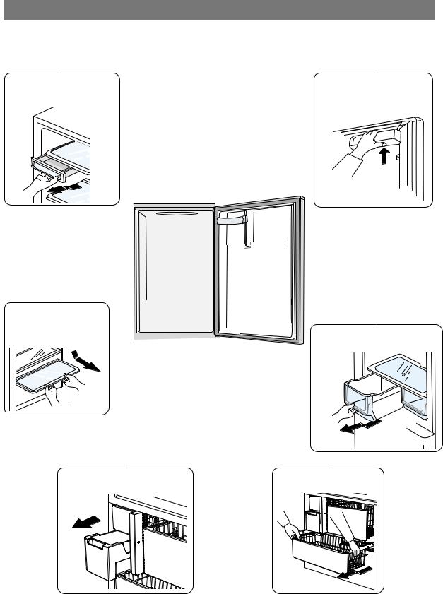
6. Interior Views and Dimensions
6-1) Shelves and Bins
• Deli drawer
Pull it out to disassemble.
Light
•Door Bin
Push it up and slide it out to disassemble.
• Glass Shelf
Pull it out until its stop Tilt down and slide it out.
•

• 
•
|
• Gallon Bin |
• |
|
• |
• Vegetable Drawer |
|
•
•
• Ice trays |
• Freezer Drawer |
8
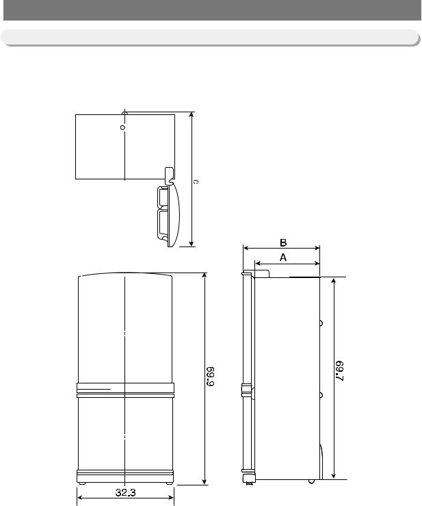
Interior Views and Dimensions
6-2) Dimensions of Refrigerator (Inches)
MODEL |
A |
|
B |
C |
RB195 |
24.3 |
|
28.3 |
57.8 |
RB215 |
26.3 |
|
30.3 |
59.8 |
|
|
9 |
|
|
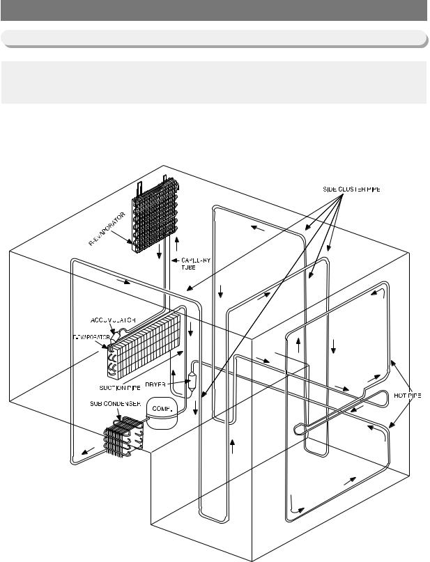
7. Refrigeration Cycle and Cool Air Circulation Route
7-1) Refrigerant Route in Refrigeration cycle
Compressor → Sub condenser → Cluster pipe → Hot pipe → Dryer → Capillary tube → R-Evaporator → F-Evaporator → Accumulator → Suction pipe → Compressor
10
Refrigeration Cycle and Cool Air Circulation Route
7-2) Cool Air Circulation
11

8. Mechanical Disassembly
Refrigerator Disassembly
Control Panel ∙∙∙∙∙∙∙∙∙∙∙∙∙∙∙∙∙∙∙∙∙∙∙∙∙∙∙∙∙∙∙∙∙∙∙∙∙∙∙∙ 13 Refrigerator Light ∙∙∙∙∙∙∙∙∙∙∙∙∙∙∙∙∙∙∙∙∙∙∙∙∙∙∙∙∙∙∙∙∙∙∙∙∙∙ 14
Freezer Light ∙∙∙∙∙∙∙∙∙∙∙∙∙∙∙∙∙∙∙∙∙∙∙∙∙∙∙∙∙∙∙∙∙∙∙∙∙∙∙∙ 14
Evaporator Cover in the Refrigerator ∙∙∙∙∙∙∙∙∙∙∙∙∙∙∙∙∙∙∙∙∙∙∙∙∙∙ 15
Evaporator Cover in the Freezer ∙∙∙∙∙∙∙∙∙∙∙∙∙∙∙∙∙∙∙∙∙∙∙∙∙∙∙∙∙ 16
Evaporator in the Freezer ∙∙∙∙∙∙∙∙∙∙∙∙∙∙∙∙∙∙∙∙∙∙∙∙∙∙∙∙∙∙∙∙∙ 17
Evaporator in the Refrigerator ∙∙∙∙∙∙∙∙∙∙∙∙∙∙∙∙∙∙∙∙∙∙∙∙∙∙∙∙∙∙ 17
Machine Compartment Electric Box ∙∙∙∙∙∙∙∙∙∙∙∙∙∙∙∙∙∙∙∙∙∙∙∙∙∙18
12
Mechanical Disassembly
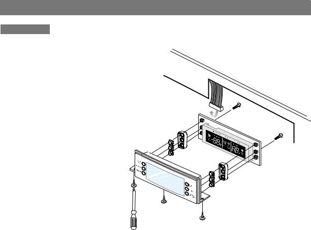
Control Panel
1.Remove the screws.
2.Pull out the control panel.
3.Disconnect the wire connector.
13
Mechanical Disassembly
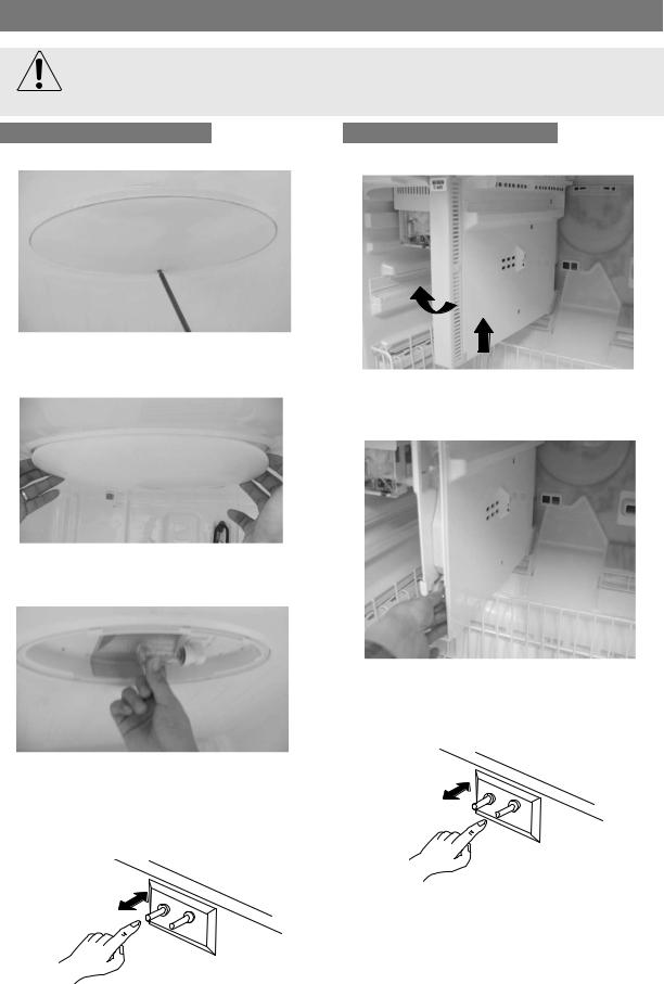
Always unplug the power cord before replacing the refrigerator lamp.
There is the danger of electric shock.
Warning
Refrigerator Light
1. Remove the screw.
2.Remove the lamp cover by unlocking the tabs and pulling the cover down.
3.Replace the lightbulb by turning it counterclockwise.
4.After replacing the bulb, reattach the cover and the screw it again.
5.Plug the power cord in and check the lamp by pressing the R-door switch.
Freezer Light
1. Remove the cover by pressing the bottom tab.
2.Replace the two bulb by turning it counter-clock wise.
3.Reattach the cover and check the lamp by pressing door switch.
14
Mechanical Disassembly
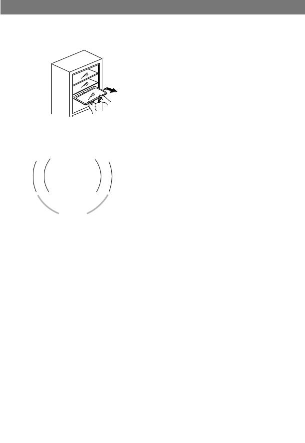
Evaporator Cover in the Refrigerator
1.Remove all shelves and drawers from the refrigerator.
2.Pull out the screw caps with a small flat-blade screwdriver.
3.Remove 6 Phillps screws from the cover.
4.Unlock the 2 tabs with a flat-blade screwdriver on each side of the bottom cover.
5.Remove the evaporator cover by pulling out from the bottom of the evaporator cover.
6. Disconnect the wire connector.
■Ductwork of the evaporator fan assembly.
15
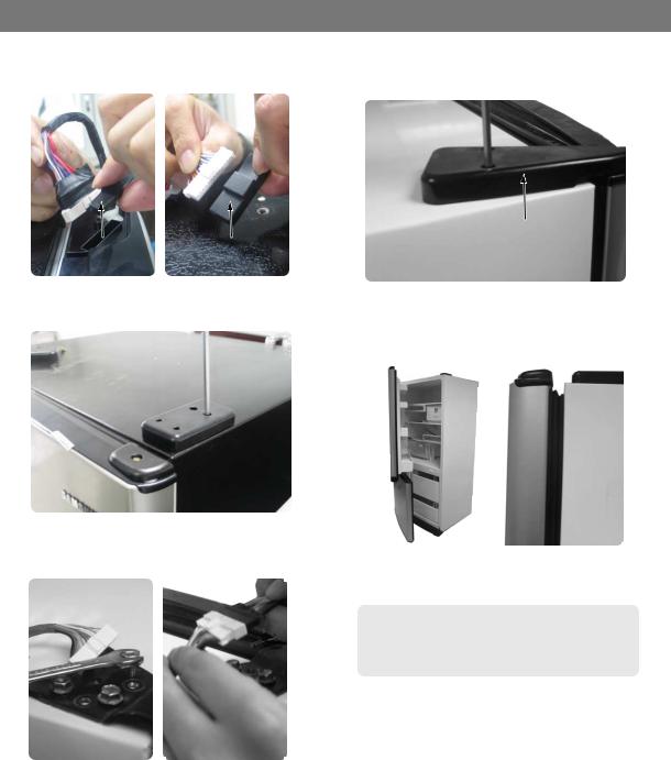
Mechanical Disassembly
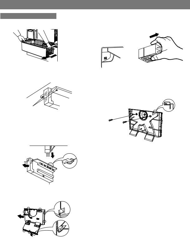
Evaporator Cover in Freezer
1. Remove all drawers from the freezer.
2. Remove screws (2) from the support rail.
2screws
3.Pull down the holder of the support rail and disconnect the wire connector to remove it.

4.Unlock the tabs around the evaporator cover from the buttom.


|
5.Disconnect wire connector from the top-left corner.
6.Remove 2 screws from the rear cover of the freezer evaporator and unlock the tabs to remove it.
16

Mechanical Disassembly
Evaporator in Refrigerator
Evaporator is located in the bottom of refrigerator.
1.Take off the ductwork in refrigerator.
2.Disconnect the wire connector.(Heater and Thermistor)
3.Desolder the capillary tube and the suction line from the evaporator.
4.Remove the evaporator.
5.With a file, score the capillary tube just upstream of the soldered point. Break off the soldered section to help prevent solder from plugging the tube during soldering.
6.Place a new evaporator and braze the suction and capillary tube to evaporator using silver solder.
7.Install a replacement dryer.
8.Evacuate and recharge the system using reasonable procedures.
Evaporator in Freezer
Evaporator is located in the bottom of freezer to produce cold air driven across the evaporator coils.
1.Take off the ductwork in Freezer.
2.Disconnect the wire connector (Heater, Bimental, and Thermistor).
3.Desolder the inlet and outlet tubes.
4.Remove the evaporator.
5.Take the same steps to seal the system as mentioned earlier.
Accumulator
Thermal
Fuse
Thermal |
Thermistor |
Fuse |
|
Thermistor
17
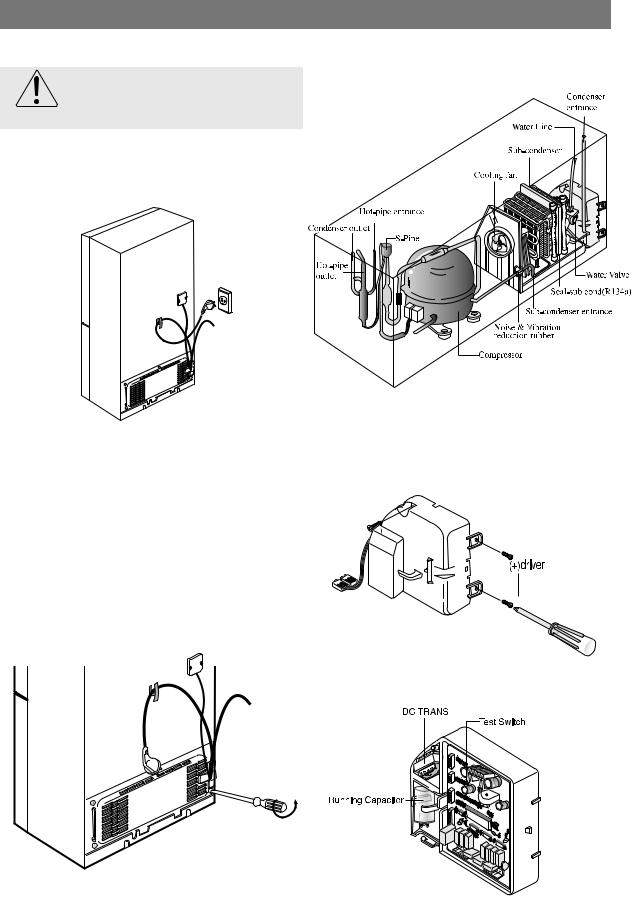
Mechanical Disassembly
Machine Compartment Electric Box |
3. Mechine compartment assembly |
Make sure the power cord is unplugged before replacing any
Warning electric components.
1. Unplug the power cord.
4. Disassemble the electric box cover after removing the screws with a Phillips screwdriver.
2. Remove the screws of the compartment cover. Slide it up and take out from the refrigerator.
5. Electric box assembly
18
9.REVERSING THE DOOR SWING Read these instructions completely and carefully
-IMPORTANT NOTES
Unplug the refrigerator from its electrical outlet.
Empty all door guards / racks.
Warning
1.If you want to change the door direction, call 1-800-SAMSUNG.
2.Read the instructions carefully before starting.
3.Handle parts carefully to avoid scrathing paint.
4.Set screws down by their related parts to avoid using them in the wrong places.
5.Provide a non-scratching work surface for the doors. (ex : blanket)
6.During door reversing, refrigerator should not be stained with oil.
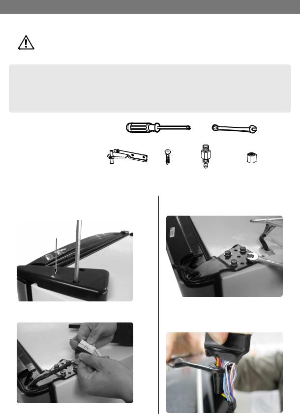
- TOOLS YOU WILL NEED
screwdriver |
10 inch wrench |
- ADDITIONAL PARTS
Hinge Mid |
Screw |
Compression |
Compression |
|
|
Fitting |
Nut |
- DISASSEMBLY THE FRIDGE DOOR
1.After removing the screw with the screwdriver, disassemble the Cover Hinge on the top of the refrigerator.
3.With the 10 inch wrench, remove the four bolts that hold the top of the refrigerator.
Cover Hinge
2. Disconnect electric wire on the top of the refrigerator. |
4. Apart Hinge from electric wire as below |
|
picture. |
19
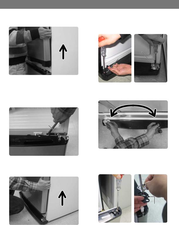
REVERSING THE DOOR SWING Read these instructions completely and carefully
5. Disassemble the fridge door by lifting it upward. |
- ASSEMBLY OF FREEZER DOOR |
Be careful not to drop and scratch the fridge door. |
8. After removing the screw, disassemble the |
|
|
|
Cover Hinge and the Hinge as below picture. |
Hinge
Cover Hinge
-DISASSEMBLY OF FREEZER DOOR
6.After removing the screw and two bolts, disassemble Hinge Mid.
Hinge Mid
7.Disassemble the Freezer Door by lifting it upward. Be careful not to drop and scratch the Freezer door.
20
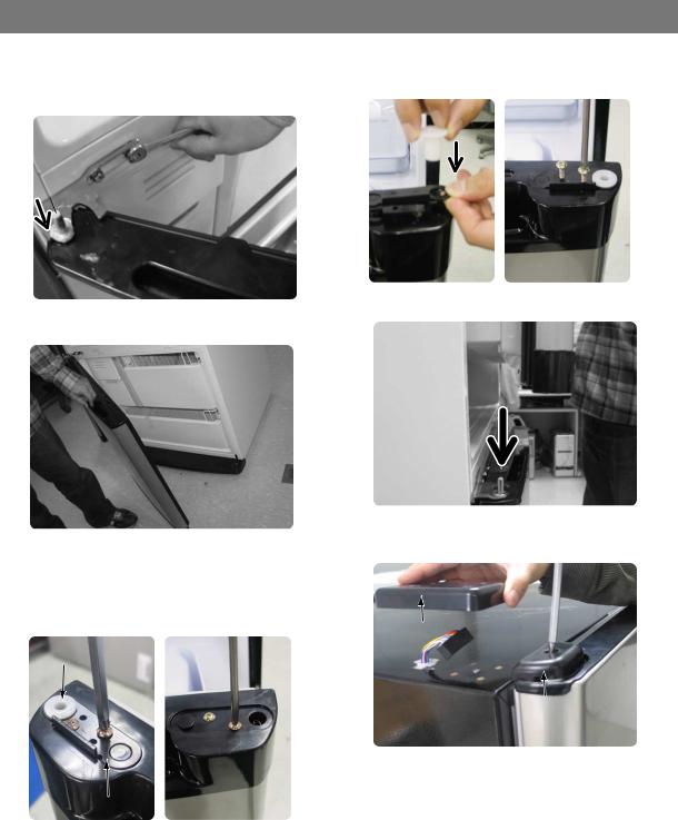
9.Assemble each part by exchanging its into the reverse side.
10.After removing the left and right side screws, disassemble the Grommet, Stopper Door and Stopper-Mid of the right bottom of freezer-door.
Stopper Mid
Stopper Door
Grommet
REVERSING THE DOOR SWING Read these instructions completely and carefully
11.Assemble each part by exchanging its into the reverse side as below picture.
12.Disassemble the Door S/W with tools. Be careful not to scratch.
14.Assemble the each part into the reverse side as below picture. Assemble the Door S/W as it is. (Make sure not to insert it upside down)
15.Assemble Freezer Door by fitting Hinge-Low into the grommet hinge hole. Don't forget to insert washer with grease.
Door S/W
13.Disassemble the Cap Door S/W, Sleeve and the screws.
Cap Door S/W
Sleeve
 Washer
16. Fix the additional Hinge mid into the door hole.
Additional 
Hinge mid
21
REVERSING THE DOOR SWING Read these instructions completely and carefully
17.Assemble the assembled hinge and door to the refrigerator as below picture. Don't forget to insert washer with grease.
20.Assemble each part by exchanging its into the reverse side as below picture.
 Washer
18. Confirm openning and closing of the door.
21. Fit the fridge door into the fixed hinge mid.
22.After removing the screw, dissemble the Cover-Cap Door and Cover Hinge.
-ASSEMBLY OF FRIDGE DOOR
19.After removing the screws, disassemble the Stopper Door and Grommet.
Grommet
Stopper Door
Cover Hinge
Cover Cap Door
22
REVERSING THE DOOR SWING Read these instructions completely and carefully
23.After disassembling Grommet and Cap wire at the left side, assemble them into the right side.
26.Assemble the Cover Hinge with the screws as below picture.
Cover Hinge
Grommet |
Cap wire |
24. Assemble the parts to the reverse side. Electric wires must be sealed in covers.
25.Assembling Hinge on the top of the refrigerator with the bolts. And then connect the electric wire.
27.Finally, confirm openning and closing of the fridge door.
After door reversing, it is necessary to check and
adjust the gasket whether it is entirely contact the
cabinet or not.
23
10. INSTALLATION OF THE WATER LINE
10-1) Before You Install the water line
•This water line installation is not warranted by the refrigerator or icemaker manufacturer. Follow these instructions carefully to minimize the risk of expensive water damage.
•Banging pipes (water banging in the pipes) in house plumbing can cause damage to refrigerator parts and lead to water leakage or flooding. Call a qualified plumber to correct the problem before installing the water supply line to the refrigerator.
•To prevent burns and product damage, do not hook up the water line to the hot water line.
•Do not install the icemaker tubing in areas where temperatures fall below freezing.
•When using any electrical device (such as a power drill) during installation, be sure the device is insulated or wired in a manner to prevent electric shock.
•All installations must be in a accordance with local plumbing code requirements.
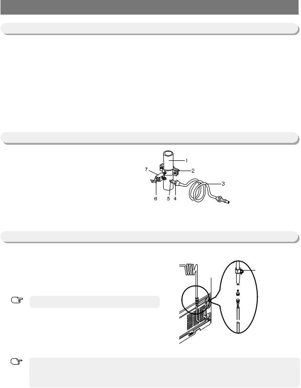
10-2) Connecting to water supply line
-Shut off the main water supply line and turn the Ice maker to the off position.
-Locate the nearest cold drinking water line.
-Follow the instructions in the ice maker installation kit.
-After connecting the water supply with water filter, turn on water supply and flush 4 or more gallons into bucket to clear the water filter
1.Cold Water line
2.Pipe Clamp. 3.Copper (or Plastic) line 4.Compression Nut 5.Compression Sleeve 6.Shut Off Valve 7.Packing Nut.
10-3) Connect the water line to the refrigerator
-Slip the compression nut through the plastic tube.
-After inserting the compression nut into plastic tube,
tighten the compres-sion nut onto 1/4” compression fitting(union).
Do not overtighten the compression nut.
NOTE
- Slip the compression ferrule and nut on copper(or plastic) tubing as shown.
After inserting the sleeve, tighten the comperssion nut onto the com-pression fitting(union).
- Turn water on and check for any leakege.
- You can purchase the necessary parts through BEST BUY.
NOTE |
- Waterline must be connected to drinkable water only |
|
|
|
- Compression fitting and nut will be given inside of ice bucket. |
Compression
Nut
 Ferrule

 Sleeve
 Compression
fitting

 Compression
Nut
24
 Loading...