

Samsung PS42Q97HDX, PS50Q97HDX Service manual
SGS0WHOHYLVLRQ FRQWHQWV
1. Precaution
2. Product Specification
3. Disassembly & Reassembly
4. Troubleshooting
5. Exploded View & Part List
6. Wiring Diagram
7. Schematic Diagram
VHUYLFH
Pdqxdo
PS-42Q97HD
PS-50Q97HD
SGS0WHOHYLVLRQ
Fkdvvlv = I63D+SbHxurshbKG,bFdood#
Prgho = SV75T<:KG[2[HX#
SV83T<:KG[2[HX#
Refer to the service manual in the GSPN (see the rear cover) for the more information.
This Service Manual is a property of Samsung Electronics Co.,Ltd.
Any unauthorized use of Manual can be punished under applicable
International and/or domestic law.
© Samsung Electronics Co., Ltd. Mar. 2007
Printed in Korea
AA82-04355A
Area Web Site
North America service.samsungportal.com
Latin America latin.samsungportal.com
CIS cis.samsungportal.com
Europe europe.samsungportal.com
China china.samsungportal.com
Asia asia.samsungportal.com
Mideast & Africa mea.samsungportal.com
GSPN (Global Service Partner Network)

Table of Contents
Chapter 1 Precaution
■ 1-1 Safety Precautions . . . . . . . . . . . . . . . . . . . . . . . . . . . . . . . . . . . . . . . . . . . . . . . . . . . . . . . . . . . 1-1
■ 1-2 Servicing Precautions . . . . . . . . . . . . . . . . . . . . . . . . . . . . . . . . . . . . . . . . . . . . . . . . . . . . . . . . 1-3
■ 1-3 Static Electricity Precautions . . . . . . . . . . . . . . . . . . . . . . . . . . . . . . . . . . . . . . . . . . . . . . . . . . . 1-4
■ 1-4 Installation Precautions . . . . . . . . . . . . . . . . . . . . . . . . . . . . . . . . . . . . . . . . . . . . . . . . . . . . . . . 1-5
Chapter 2 Product Specification
■ 2-1 Product Specification . . . . . . . . . . . . . . . . . . . . . . . . . . . . . . . . . . . . . . . . . . . . . . . . . . . . . . . . . 2-1
■ 2-2 Specifications Analysis . . . . . . . . . . . . . . . . . . . . . . . . . . . . . . . . . . . . . . . . . . . . . . . . . . . . . . . . 2-3
■ 2-3 Accessories . . . . . . . . . . . . . . . . . . . . . . . . . . . . . . . . . . . . . . . . . . . . . . . . . . . . . . . . . . . . . . . . 2-4
Chapter 3 Disassembly & Reassembly
■ 3-1 Overhaul Disassembly & Reassembly . . . . . . . . . . . . . . . . . . . . . . . . . . . . . . . . . . . . . . . . . . . . 3-1
Chapter 4 Troubleshooting
■ 4-1 Troubleshooting . . . . . . . . . . . . . . . . . . . . . . . . . . . . . . . . . . . . . . . . . . . . . . . . . . . . . . . . . . . . . 4-1
■ 4-2 Adjustment . . . . . . . . . . . . . . . . . . . . . . . . . . . . . . . . . . . . . . . . . . . . . . . . . . . . . . . . . . . . . . . . . 4-16
■ 4-3 Upgrade . . . . . . . . . . . . . . . . . . . . . . . . . . . . . . . . . . . . . . . . . . . . . . . . . . . . . . . . . . . . . . . . . . . 4-32
Chapter 5 Exploded View & Part List
■ 5-1 PS42Q97HDX/XEU Exploded View . . . . . . . . . . . . . . . . . . . . . . . . . . . . . . . . . . . . . . . . . . . . . . 5-1
■ 5-2 PS50Q97HDX/XEU Exploded View . . . . . . . . . . . . . . . . . . . . . . . . . . . . . . . . . . . . . . . . . . . . . . 5-3
■ 5-3 PS42Q97HDX/XEU Service Item . . . . . . . . . . . . . . . . . . . . . . . . . . . . . . . . . . . . . . . . . . . . . . . . 5-5
■ 5-4 PS50Q97HDX/XEU Service Item . . . . . . . . . . . . . . . . . . . . . . . . . . . . . . . . . . . . . . . . . . . . . . . . 5-6
Chapter 6 Wiring Diagram
■ 6-1 Overall Wiring . . . . . . . . . . . . . . . . . . . . . . . . . . . . . . . . . . . . . . . . . . . . . . . . . . . . . . . . . . . . . . . 6-1
Chapter 7 Schematic Diagram
■ 7-1 Circuit Description . . . . . . . . . . . . . . . . . . . . . . . . . . . . . . . . . . . . . . . . . . . . . . . . . . . . . . . . . . . 7-1
■ 7-2 Schematic Diagram . . . . . . . . . . . . . . . . . . . . . . . . . . . . . . . . . . . . . . . . . . . . . . . . . . . . . . . . . . 7-3
1. Make sure all protective devices are properly installed
including non-metallic handles and compartment covers
when installing or re-installing the chassis or chassis
assemblies.
2. Make sure that no gaps exist between the cabinets for
children to insert their fingers in to prevent children from
receiving electric shocks. Gaps mentioned above include
ventilation holes between the PDP module and the cabinet mask, and the improper installation of the rear cabinet.
Errors may occur when the resistance is below 1.0 ㏁ or
over 5.2 ㏁.
In these cases, make sure that the device is repaired
before sending it back to the customer.
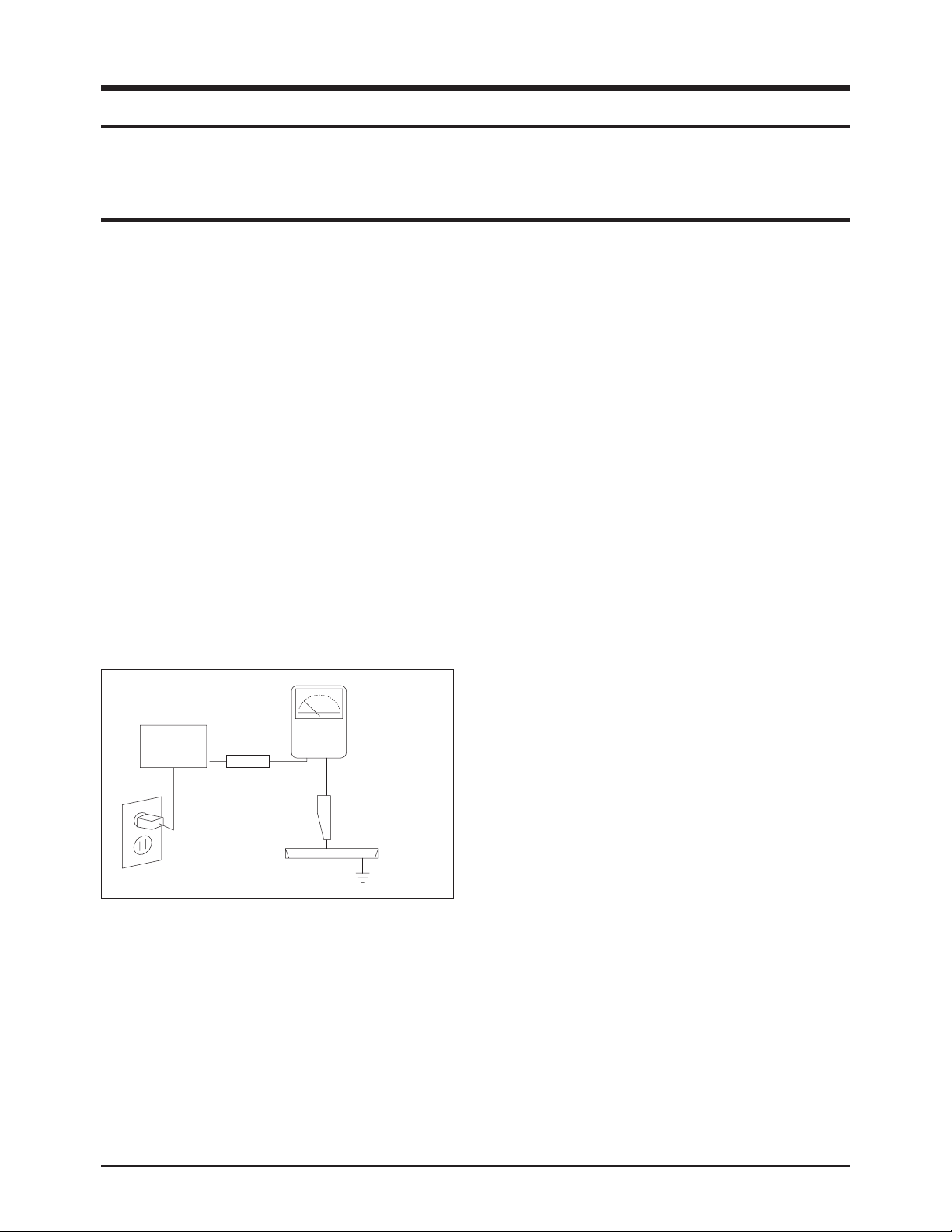
3. Check for Electricity Leakage (Figure 1-1)
Warning: Do not use an insulated transformer for checking the leakage. Use only those current leakage testers
or mirroring systems that comply with ANSIC 101.1 and
the Underwriter Laboratory's specifications (UL1410,
59.7).
Fig. 1-1 AC Leakage Test
4. Ahigh voltage is maintained within the specified limits
using safety parts, calibration and tolerances. When
voltage exceeds the specified limits, check each special
part.
5. Warning for Engineering Changes:
Never make any changes or additions to the circuit
design or the internal part for this product.
Ex: Do not add any audio or video accessory
connectors. This might cause physical damage.
Furthermore, any changes or additions to the original
design/engineering will invalidate the warranty.
6. Warning - Hot Chassis:
Some TV chassis are directly connected to one end of
the AC power cord for electrical reasons.
Without insulated transformers, the product can only be
repaired safely when the chassis is connected to the
earth end of the AC power source.
To make sure the AC power cord is properly connected,
follow the instructions below. Use the voltmeter to
measure the voltage between the chassis and the
earth ground. If the measurement is over 1.0V, unplug
the AC power cord and change the polarity before reinserting it. Measure the voltage between the chassis
and the ground again.
7. Some TV chassis are shipped with an additional secondary grounding system. The secondary system is
adjacent to the AC power line. These two grounding
systems are separated in the circuit using an unbreakable/unchangeable insulation material.
8. When any parts, material or wiring appear overheated or
damaged, replace them with new immediately. When
any damage or overheating is detected, correct this
immediately and make a regular check of possible
errors.
9. Check for the original shape of the lead, especially that
of the antenna wiring, any sharp edges, the AC power
and the high voltage power. Carefully check if the wiring
is too tight, incorrectly placed or loose. Never change the
space between the part and the printed circuit board.
Check the AC power cord for possible damages. Keep
the part or the lead away from any heat-emitting
materials.
Precaution
Samsung Electronics 1-1
To avoid possible damage or electric shocks or exposure to radiation, follow the instructions below with regard to safety, installation, service and ESD.
1. Precaution
1-1 Safety Precautions
(READING SHOULD
DEVICE
UNDER
TEST
EXPOSED METAL
2-WIRE CORD
ALSO TEST WITH
PLUG REVERSED
(USING AC ADAPTER
PLUG AS REQUIRED)
TEST ALL
SURFACES
LEAKAGE
CURRENT
TESTER
NOT BE ABOVE
0.5mA)
EARTH
GROUND

10. Safety Indication:
Some electrical circuits or device related materials
require special attention to their safety features, which
cannot be viewed by the naked eye. If an original part is
replaced with another irregular one, the safety or
protective features will be lost even if the new one has a
higher voltage or more watts.
Critical safety parts should be bracketed with ( ).
Use only regular parts for replacements (in particular,
flame resistance and dielectric strength specifications).
Irregular parts or materials may cause electric shock or
fire.
Precaution
1-2 Samsung Electronics
!

1. The service instructions are printed on the cabinet, and
should be followed by any service personnel.
2. Make sure to unplug the AC power cord from the power
source before starting any repairs.
(a) Remove or re-install parts or assemblies.
(b) Disconnect the electric plug or connector, if any.
(c) Connect the test part in parallel with the electrolytic
capacitor.
3. Some parts are placed at a higher position than the
printed board. Insulated tubes or tapes are used for this
purpose. The internal wiring is clamped using buckles to
avoid contact with heat emitting parts. These parts are
installed back to their original position.
4. After the repair, make sure to check if the screws, parts
or cables are properly installed. Make sure no damage is
caused to the repaired part and its surroundings.
5. Check for insulation between the blade of the AC plug
and that of any conductive materials (i.e. the metal
panel, input terminal, earphone jack, etc).
6. Insulation Check Process: Unplug the power cord from
the AC source and turn the switch on. Connect the insulating resistance meter (500v) to the AC plug blade.
The insulating resistance between the blade of the AC
plug and that of the conductive material should be more
than 1 ㏁.
7. Any B+ interlock should not be damaged.
If the metal heat sink is not properly installed, no
connection to the AC power should be made.
8. Make sure the grounding lead of the tester is connected
to the chassis ground before connecting to the positive
lead. The ground lead of the tester should be removed
last.
9. Beware of risks of any current leakage coming into
contact with the high-capacity capacitor.
10. The sharp edges of the metal material may cause
physical damage, so protect yourself by wearing gloves
during the repair.
11. Due to the nature of plasma display panels, partial afterimages may appear if a still picture is displayed on the
screen for a long period of time.
This is caused by brightness deterioration due to the
storage effect of the panel, and to prevent this from
happening, we recommend that the brightness and contrast are reduced.
(e.g.) Contrast: 25, Brightness: 50
Precaution
Samsung Electronics 1-3
Warning 1: First carefully read the "Safety Instruction" in this service manual.
When there is a conflict between the service and the safety instructions, follow the safety instruction at all times.
Warning 2: Any electrolytic capacitor with the wrong polarity will explode.
1-2 Servicing Precautions

1-3 Static Electricity Precautions
1. Some semi-conductive ("solid state") devices are
vulnerable to static electricity. These devices are known
as ESD. ESD includes the integrated circuit and the field
effect transistor. To avoid any materials damage from
electrostatic shock, follow the instructions described
below.
2. Remove any static electricity from your body by
connecting the earth ground before handling any
semi-conductive parts or assemblies. Alternatively,
wear a dischargeable wrist-belt.
(Make sure to remove any static electricity before
connecting the power source - this is a safety instruction
for avoiding electric shock)
3. Remove the ESD assembly and place it on a conductive
surface such as aluminum foil to prevent accumulating
static electricity.
4. Do not use any Freon-based chemicals.
Such chemicals will generate static electricity that
causes damage to the ESD.
5. Use only grounded-tip irons for soldering purposes.
6. Use only anti-static solder removal devices.
Most solder removal devices do not support an
anti-static feature. Asolder removal device without an
anti-static feature can store enough static electricity to
cause damage to the ESD.
7. Do not remove the ESD from the protective box until the
replacement is ready. Most ESD replacements are
covered with lead, which will cause a short to the entire
unit due to the conductive foam, aluminum foil or other
conductive materials.
8. Remove the protective material from the ESD
replacement lead immediately after connecting it to the
chassis or circuit assembly.
9. Take extreme caution in handling any uncovered ESD
replacements. Actions such as brushing clothes or lifting
your leg from the carpet floor can generate enough static
electricity to damage the ESD.
Precaution
1-4 Samsung Electronics
CAUTION
These servicing instructions are for use by
qualified service personnel only.
To reduce the risk of electric shock do not
perform any servicing other than that contained in the
operating instructions unless you are qualified to do so.

Precaution
Samsung Electronics 1-5
1-4 Installation Precautions
1. For safety reasons, more than two people are required
for carrying the product.
2. Keep the power cord away from any heat emitting
devices, as a melted covering may cause fire or electric
shock.
3. Do not place the product in areas with poor ventilation
such as a bookshelf or closet. The increased internal
temperature may cause fire.
4. Bend the external antenna cable when connecting it to
the product. This is a measure to protect it from being
exposed to moisture. Otherwise, it may cause a fire or
electric shock.
5. Make sure to turn the power off and unplug the power
cord from the outlet before repositioning the product.
Also check the antenna cable or the external connectors
if they are fully unplugged. Damage to the cord may
cause fire or electric shock.
6. Keep the antenna far away from any high-voltage cables
and install it firmly. Contact with the high-voltage cable or
the antenna falling over may cause fire or electric shock.
7. When connecting the RF antenna, check for a DTV
receiving system and install a separate DTV reception
antenna for areas with no DTV signal.
8. When installing the product, leave enough space (4")
between the product and the wall for ventilation
purposes.
Arise in temperature within the product may cause fire.
9. When moving a PDP with removable speakers, detach
the speakers first before moving the main body.
Moving the PDP main body without separating the
speakers may cause the speakers to detach, possibly
causing damage or injury.

1-6 Samsung Electronics
MEMO
Product Specification
Samsung Electronics 2-1
2. Product Specification
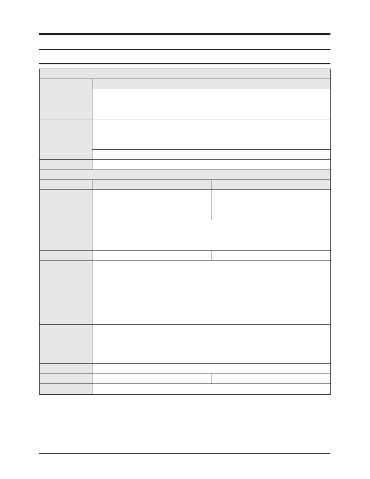
2-1 Product Specification
Features
Block Specfication Major IC Remark
RF Tuner DNOS403MH261B(S) SEMCO
PDP Module Samsung SDI W2A 42"HD/50"HD SAMSUNG SDI
Power Input Voltage: AC 100~240V, 50/60Hz
Video
Scaler
SVP-UX68
Video Decoder
Sound
Sound AMP NTP3000 Neo Fidelity
Audio CODEC SGTV5810
Cabinet Q9 Design
Specification
Model PS-42Q97HD PS-50Q97HD
Screen Size 42 Inches (16:9) 50 Inches (16:9)
Dimensions (WxHxD) 1055 x 759 x 316 mm (With Stand) 1231 x 848.5 x 316 mm (With Stand)
Weight 33.2 kg (With Stand) 44 kg (With Stand)
Voltage AC 100~240V, 50/60Hz
Colour System PAL, SECAM, NTSC4.43, NTSC 3.58
Sound System BG, DK, I, M
PC Resolution 1024 x 768 @ 75Hz 1365 x 768 @ 75Hz
ANTENNAinput AIR IN (75Ωunbalanced)
VIDEO input
SCART1, SCART2
AV (Side), S-VIDEO (Side)
COMPONENT IN (480i/P, 576i/P, 720P, 1080i)
PC IN (MINI D-SUB 15P)
HDMI1
HDMI2 (DVI IN)
HDMI3 (Side)
AUDIO input
SCART1, SCART2
AV (Side), S-VIDEO (Side)
Component
PC
DVI
Audio Output AUDIO (L/R)
Speaker Output 10W + 10W 15W + 15W
New Features Anynet+
Product Specification
2-2 Samsung Electronics
■■
New Features explanation
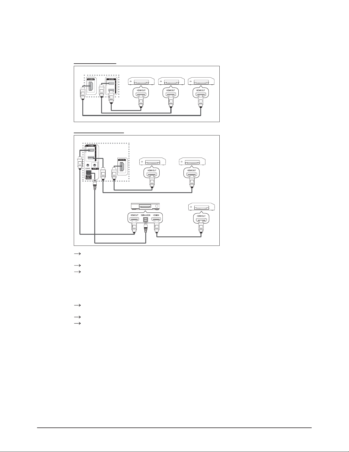
- Anynet+ : Anynet+ is an AV network system that enables you to control all connected Samsung AV devices with your
Samsung TV's remote.
To directly connect to TV
TV
Anynet+ Device 1 Anynet+ Device 2 Anynet+ Device 3
Connect the [HDMI 1], [HDMI
2] or [HDMI 3] jack on the TV
and the HDMI OUT jack of the
corresponding Anynet+ device
using the HDMI cable.
HDMI Cable
HDMI Cable
HDMI Cable
To connect to Home Theater
TV
1 Connect the [HDMI 1],
[HDMI 2] or [HDMI 3]
jack on the TV and the
Anynet+ Device 1 Anynet+ Device 2
HDMI OUT jack of the
corresponding Anynet+
device using the HDMI
cable.
2 Connect the HDMI IN jack
HDMI Cable
Home Theater
HDMI Cable
Anynet+ Device 3
of the home theater and
the HDMI OUT jack of the
corresponding Anynet+
device using the HDMI
cable.
HDMI Cable
Optical Cable
HDMI Cable
Connect only the optical cable between [Digital Audio Out (Optical)] on your TV and Digital Audio
Input on the receiver.
Connect only one receiver.
You can listen to 5.1 channel sound through the home theater’s speakers. Otherwise, you can only
listen to 2 channel stereo sound in other cases. Make sure to connect the Digital Audio IN (Optical) of
the home theater and the TV correctly to listen to TV sound through the home theater. However, you
cannot listen to sound from the BD recorder that is sent to the home theater via the TV in 5.1 channel
sound because the TV outputs only 2 channel stereo sound. Please see the manual for the home
theater.
You can connect an Anynet+ device using the HDMI cable. Some HDMI cables may not support
Anynet+ functions.
Anynet+ works when the AV device supporting Anynet+ is in the Standby or On status.
Anynet+ supports up to 8 AV devices in total.
Product Specification
Samsung Electronics 2-3
2-2 Specifications Analysis
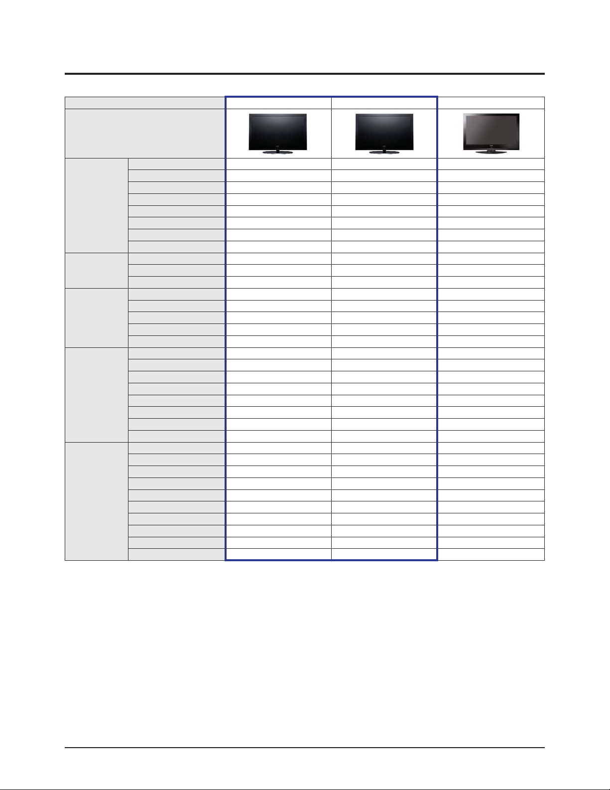
Model PS-42Q97HD (Calla-42HD) PS-50Q97HD (Calla-50HD) PS-42P7HD (Alps-42HD)
Design
Basic
Display Type PDP TV PDP TV PDP TV
Built-In Tuner O O O
PC Resolution 1024 x 768 @ 75Hz 1365 x 768 @ 75Hz 1024 x 768 @75Hz
PDP Module W2A W2A V5.1
Screen Size 42 inches 50 inches 42 inches
Aspect Ratio 16 : 9 16 : 9 16 : 9
Dimensions (WxHxD) 1055 x 759 x 316 mm (With Stand) 1231 x 848.5 x 316 mm (With Stand) 1055 x 775 x 341 mm (With Stand)
Weight 33.2 kg (With Stand) 44 kg (With Stand) 40.4 kg (With Stand)
Picture
Brightness 1,500 Cd/m2 1,300 Cd/m2 1,100 Cd/m2
Contrast Ratio 10000:1 10000:1 10000:1
Image Enhacer FBE2X FBE2X FBE
Audio
Equalizer O O O
Auto Volume O O O
Surround Sound SRS TruSurround SRS TruSurround SRS TruSurround
Speaker Output 10 W + 10 W 15 W + 15 W 15 W + 15 W
Speaker 2CH 2.2CH (2Way) Included
Features
PIP O O O
Double Screen O O X
Caption X X X
Still Image O O O
My Color Control O O X
Color Weakness X X X
Energy Saving O O O
Screen Burn Protection O O O
Connections
Antenna 1 Input 1 Input 1 Input
CVBS 1AV(Side) 1AV(Side) 1AV(Rear)
S-Video O O 1 Input
Component(Y/PB/PR) 1 Input 1 Input 1 Input
PC(D-SUB) 1 Input 1 Input 1 Input
DVI O O O
HDMI 3 Input 3 Input 2 Input
Scart 2 Input 2 Input 2 Input
Optical O O O
Coaxial X X X
※ For the power supply and power consumption, refer to the label attached to the product.
※○: application, X: non-application
Product Specification
2-4 Samsung Electronics
2-3 Accessories
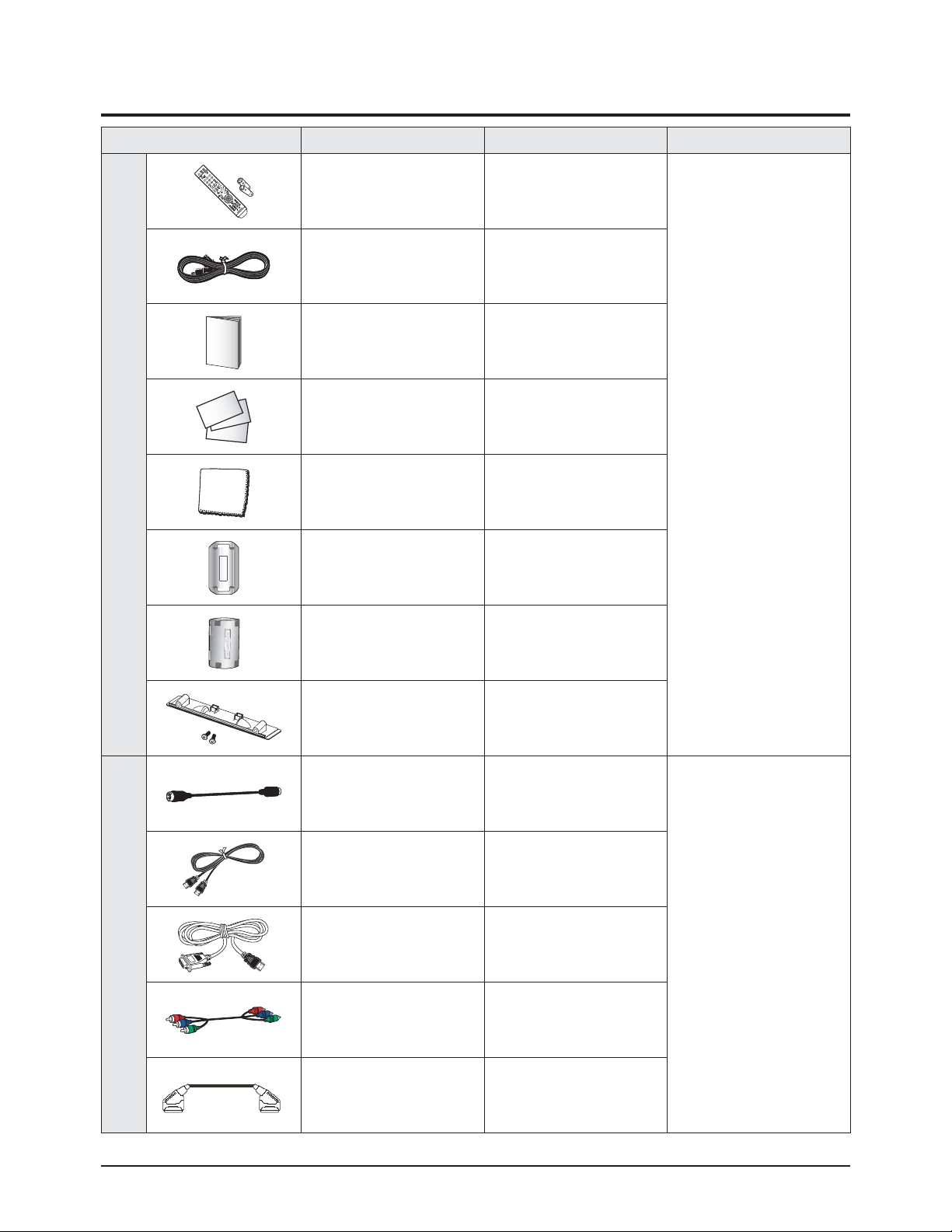
Accessories Item Item code Remark
SuppliedAccessories
Remote Control
Batteries
BN59-00603A
4301-000103
Samsung Service center
Power Cord 3903-000193
Owner's Instructions BN68-01171A
Warranty Card
Registration Card
Safety Guide Manual
BN68-00514D
AA68-03575A
AA68-03242E
Cloth-Clean BN63-01798A
Ferrite Core for
Earphone/Power Cord
3301-001110
Ferrite Core for
S-VIDEO/Power Cord
3301-001305
Cover-Bottom
Screws (2ea)
BN63-03055A
6003-001621
Accessories that canbe purchased
additionally
S-VIDEO Cable
1200mm
BN39-00149A
Electronics Store/
Internal shopping mall
HDMI Cable
3000mm
BN39-00641A
HDMI/DVI cable
3000mm
BN39-00643A
Component Cables (RCA)
1500mm
BN39-00279A
Scart Cable None
Product Specification
Samsung Electronics 2-5
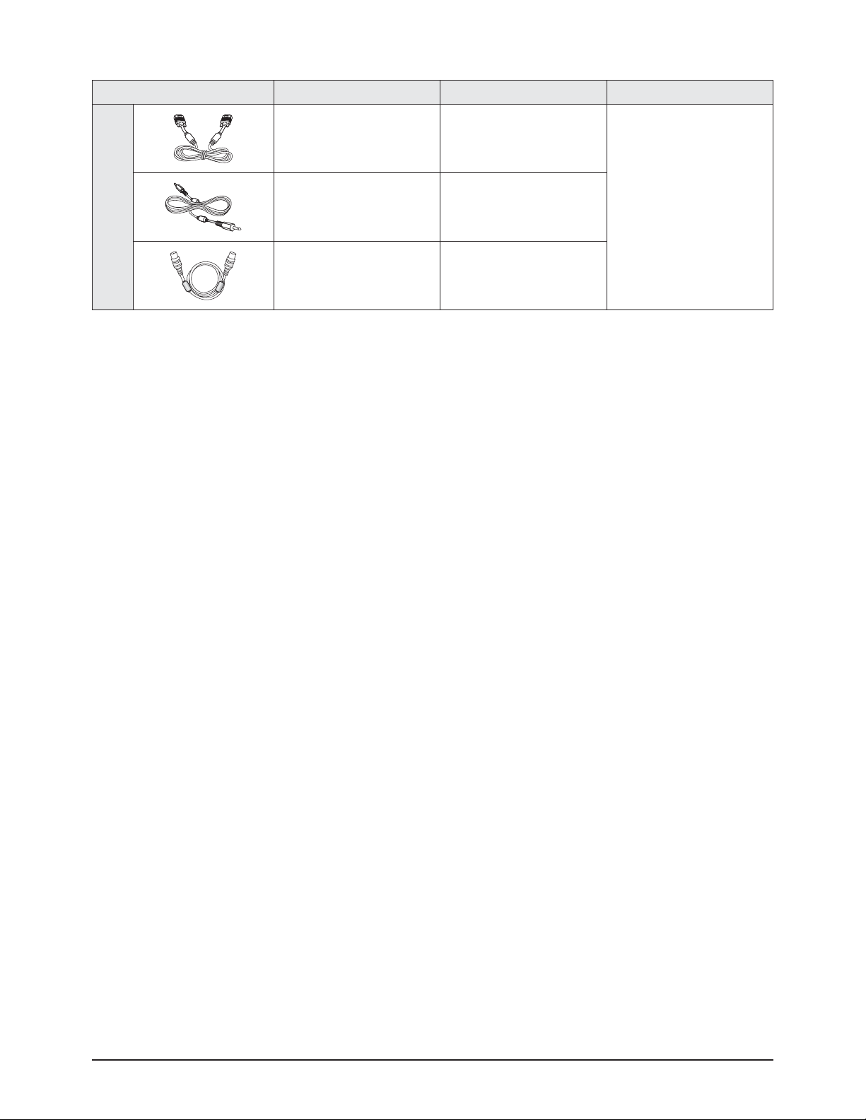
Accessories Item Item code Remark
Accessories that canbe purchased
additionally
PC Cable
1830mm
BN39-00115A
Electronics Store/
Internal shopping mall
PC Audio Cable
2000mm
BN39-00061B
Antenna Cable
3000mm
BN39-00333A

2-6 Samsung Electronics
MEMO
Part Name Description Description Photo
Cover
Rear
Disassembly & Reassembly
Samsung Electronics 3-1
3. Disassembly & Reassembly
3-1 Overall Disassembly & Reassembly
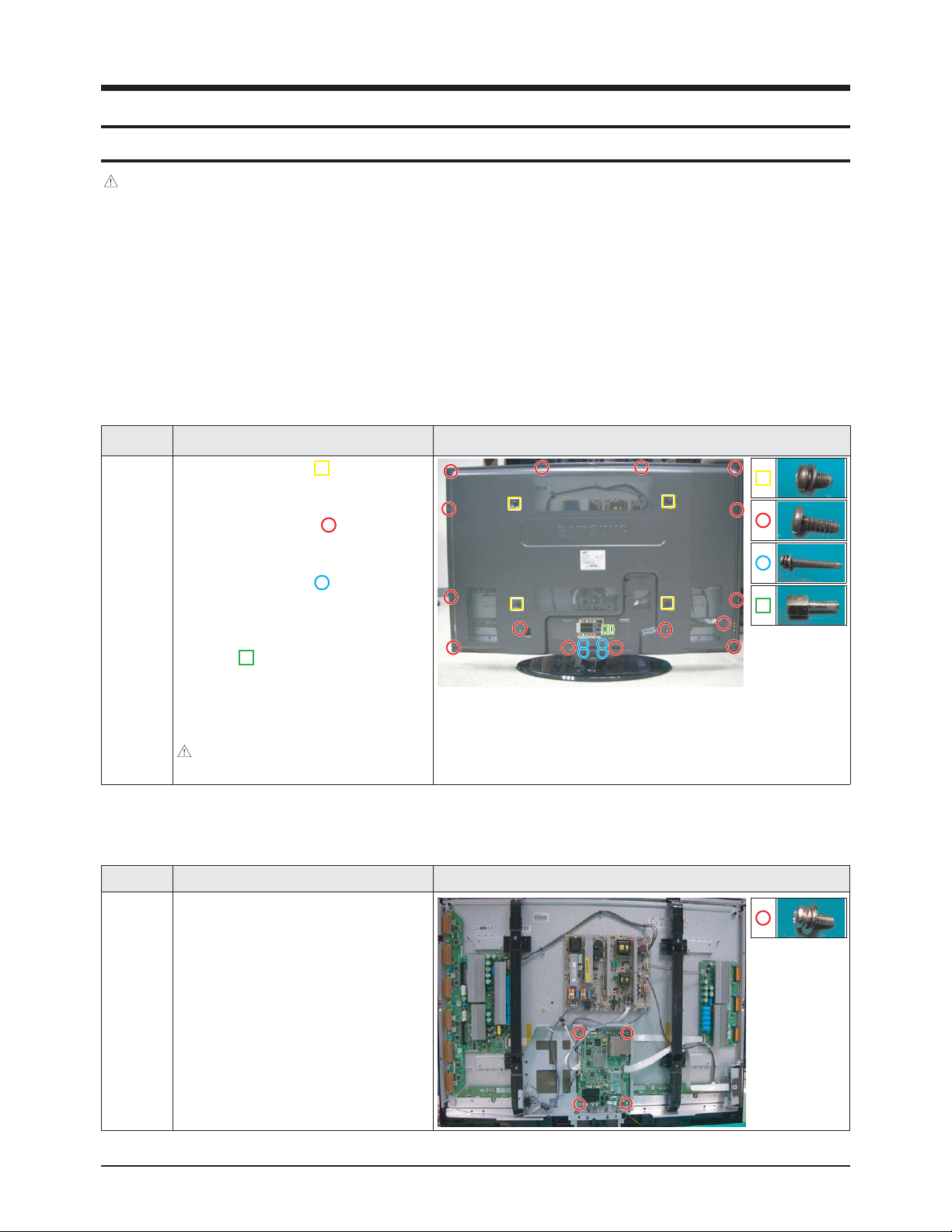
3-1-1 Separation of ASSY COVER P-REAR
3-1-2 Separation of ASSY PCB MISC-MAIN
Part Name Description Description Photo
Main
Board
① Detach all connectors from the Main
Board.
② Remove 4 screws.
: PH,+,WWP,M3,L8,NI PLT
③ Remove the Main Board.
Notice
- Be sure to separate the power cord before disassembling the unit.
- Discharge the capacitors first when separating PCB's with high capacity capacitors such as SMPS, X Main Board, YMain
Board, etc. (Aspark may be generated by the electric charge, and there is danger of electronic shock.)
- Check that the cables are properly connected referring to the circuit diagram when disassembling or assembling the unit
taking care not to damage the cables.
- Take care not to scratch the Glass Filter in the front.
- Assemble the boards in the reverse order of the disassembly.
- The plasma must be layed down on a flat padded surface for disassembly and reassembly.
① Remove 4 screws. ( )
: M8,L16,ZPC(BLK),SWRCH18A,WP
② Remove 15 screws. ( )
: BH,+,B,M4,L3,ZPC(BLK)
③ Remove 4 screws. ( )
: PH,+,WSP,S,M4,L35,ZPC(BLK)
④ Remove the 2 Hex nuts for the PC
input. ( )
: #4-40,L6,NI PLT,C3601,-
⑤ Remove the Cover Rear.
: Please lay the PDP unit face down on a
soft surface when removing the stand.
Disassembly & Reassembly
3-2 Samsung Electronics
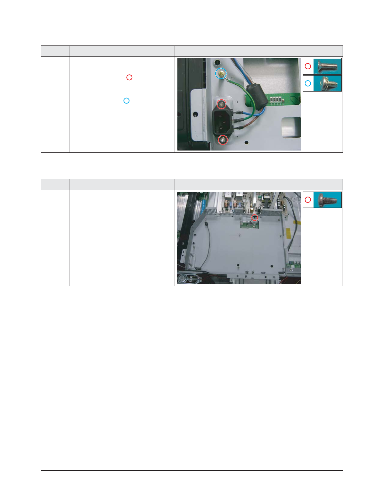
3-1-3 Separation of FILTER-EMI AC LINE
Part Name Description Description Photo
FILTER-
EMI
AC LINE
① Detach connector from Main SMPS.
② Remove 2 screws. ( )
: PH,+,WWP,M3,L8,NI PLT
③ Remove a screw. ( )
: BH,+,S,M4,L10,ZPC(BLK)
④ Remove FILTER-EMI AC LINE.
3-1-4 Separation of BRACKET-PCB
Part Name Description Description Photo
Bracket
PCB
① Remove a screw.
: BH,+,S,M4,L10,ZPC(BLK)
② Remove the BRACKET-PCB.
Disassembly & Reassembly
Samsung Electronics 3-3
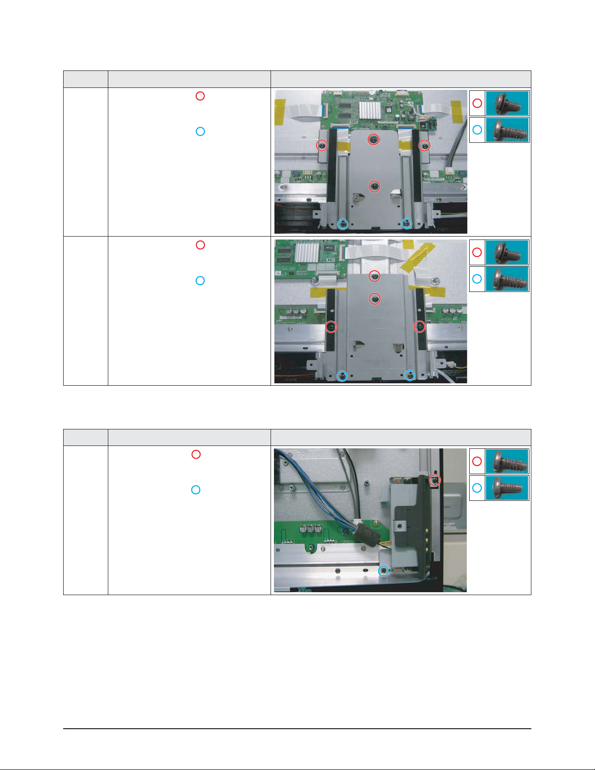
3-1-5 Separation of ASSY BRACKET
Part Name Description Description Photo
42"
Bracket
① Remove 4 screws. ( )
: BH,+,S,M4,L10,ZPC(BLK)
② Remove 2 screws. ( )
: BH,+,B,M4,L3,ZPC(BLK)
③ Remove Bracket.
50"
Bracket
① Remove 4 screws. ( )
: BH,+,S,M4,L10,ZPC(BLK)
② Remove 2 screws. ( )
: BH,+,B,M4,L3,ZPC(BLK)
③ Remove Bracket.
3-1-6 Separation of ASSY BOARD P-SIDE AV
Part Name Description Description Photo
Side AV
① Remove a screw. ( )
: BH,+,B,M4,L3,ZPC(BLK)
② Remove a screw. ( )
: BH,+,S,M4,L10,ZPC(BLK)
③ Remove the Side AV.
Disassembly & Reassembly
3-4 Samsung Electronics
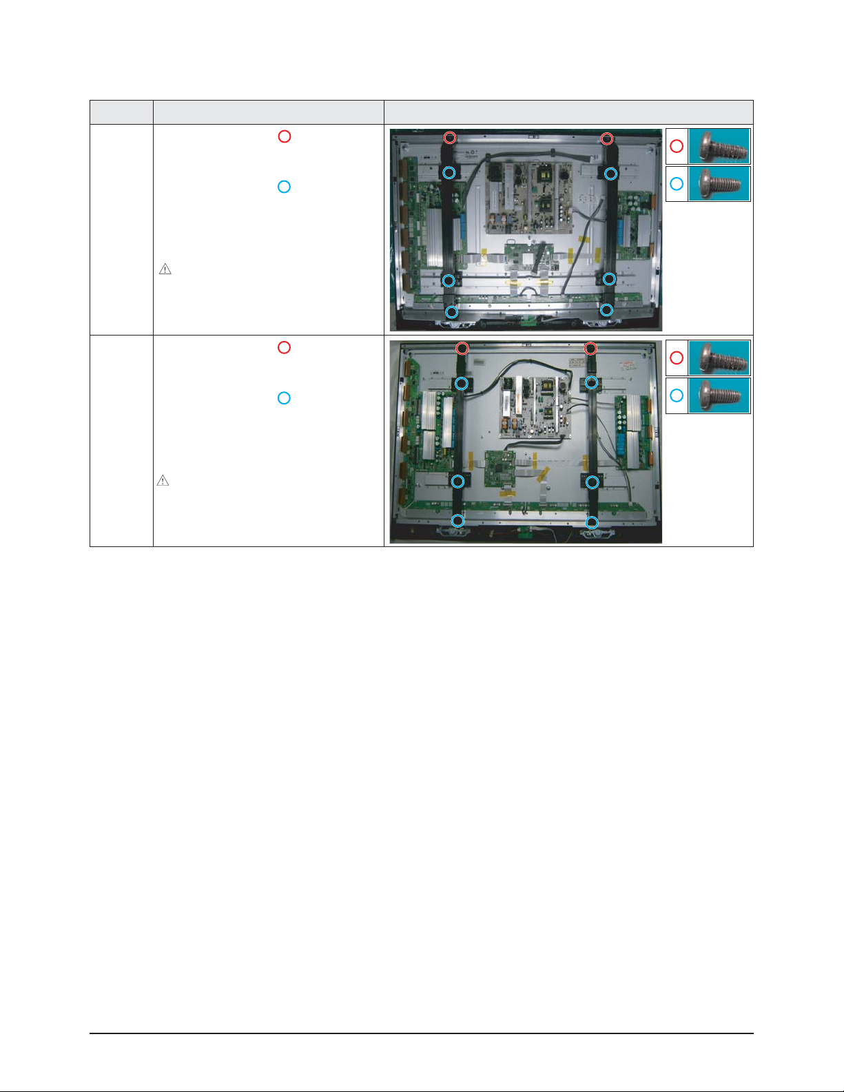
3-1-7 Separation of ASSY BRACKET P-WALL
Part Name Description Description Photo
42"
Wall
Bracket
① Remove 2 screws. ( )
: BH,+,B,M4,L3,ZPC(BLK)
② Remove 6 screws. ( )
: BH,+,S,M4,L10,ZPC(BLK)
③ Remove Wall Bracket.
: Please lay the PDP panel face down
on a soft surface when separating front
cover.
50"
Wall
Bracket
① Remove 2 screws. ( )
: BH,+,B,M4,L3,ZPC(BLK)
② Remove 6 screws. ( )
: BH,+,S,M4,L10,ZPC(BLK)
③ Remove Wall Bracket.
: Please lay the PDP panel face down on
a soft surface when separating front
cover.
Disassembly & Reassembly
Samsung Electronics 3-5
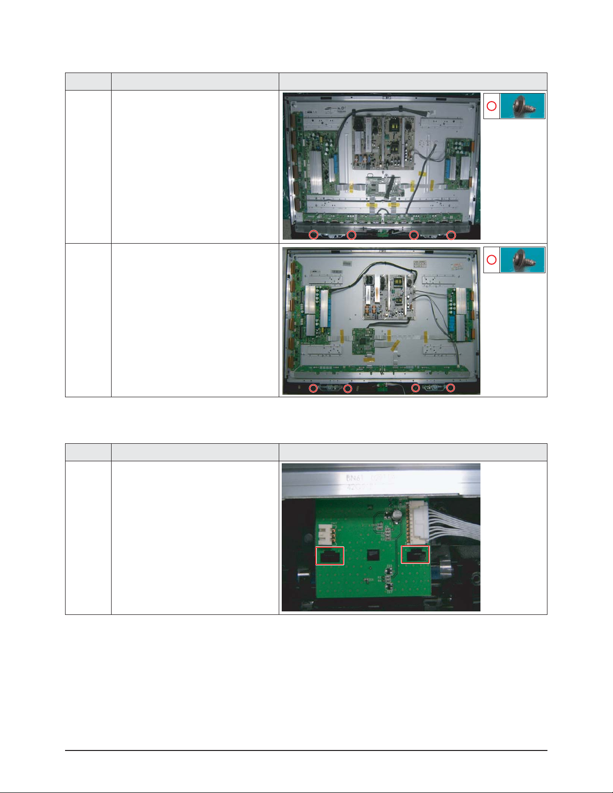
3-1-8 Separation of ASSY SPEAKER P
Part Name Description Description Photo
42"
Speaker
① Remove 4 screws.
: BH,+,WP,B,M4.0,L3,ZPC(BLK),
SWRCH18A
② Remove the Speaker.
50"
Speaker
① Remove 4 screws.
: BH,+,WP,B,M4.0,L3,ZPC(BLK),
SWRCH18A
② Remove the Speaker.
3-1-9 Separation of ASSY BOARD P-POWER&IR
Part Name Description Description Photo
Power
&
IR Board
① Detach all connectors from the
Power&IR Board.
② Remove the Power&IR PCB unlocking
the 2 holders.
Disassembly & Reassembly
3-6 Samsung Electronics
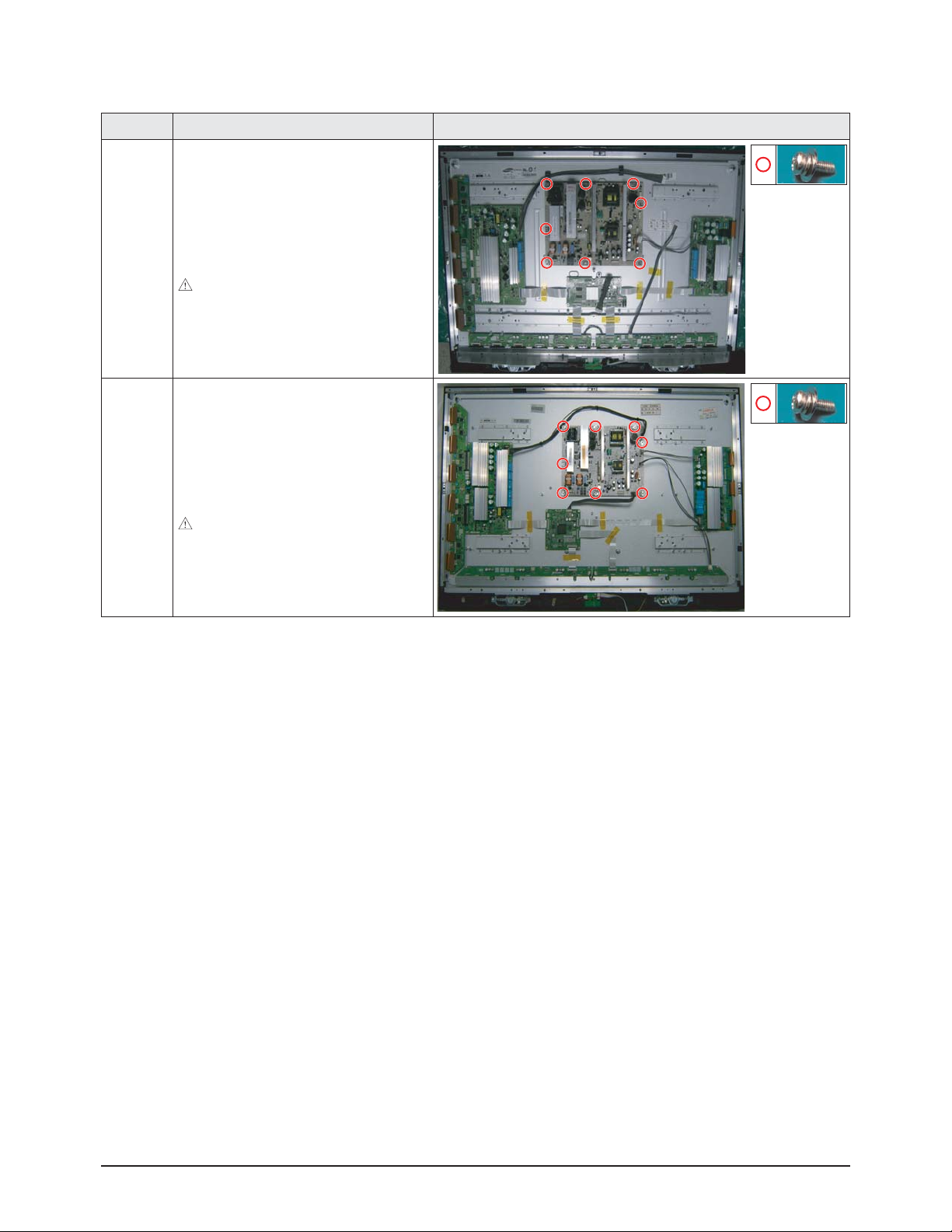
3-1-10 Separation of SMPS-PDP TV
Part Name Description Description Photo
42"
SMPS
① Detach all connectors from the SMPS.
② Remove 8 screws.
: PH,+,WWP,M3,L8,NI PLT
③ Remove the SMPS.
: Wear gloves when handling the power
board as there may be some remaining
electrical charge in the capacitor.
Specifically, avoid touching any part of
the capacitor.
50"
SMPS
① Detach all connectors from the SMPS.
② Remove 8 screws.
: PH,+,WWP,M3,L8,NI PLT
③ Remove the SMPS.
: Wear gloves when handling the power
board as there may be some remaining
electrical charge in the capacitor.
Specifically, avoid touching any part of
the capacitor.

Disassembly & Reassembly
Samsung Electronics 3-7
3-1-11 Separation of ASSY PDPMODULE P-LOGIC MAIN BOARD
Part Name Description Description Photo
42"
Logic
Board
① Detach all connectors from the Logic
Main Board.
② Remove 4 screws.
: WSP,PH,+,M3,L8,NI PLT
③ Remove the Logic Main Board.
50"
Logic
Board
① Detach all connectors from the Logic
Main Board.
② Remove 4 screws.
: WSP,PH,+,M3,L8,NI PLT
③ Remove the Logic Main Board.
Disassembly & Reassembly
3-8 Samsung Electronics
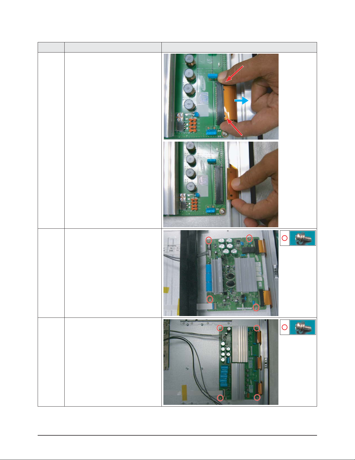
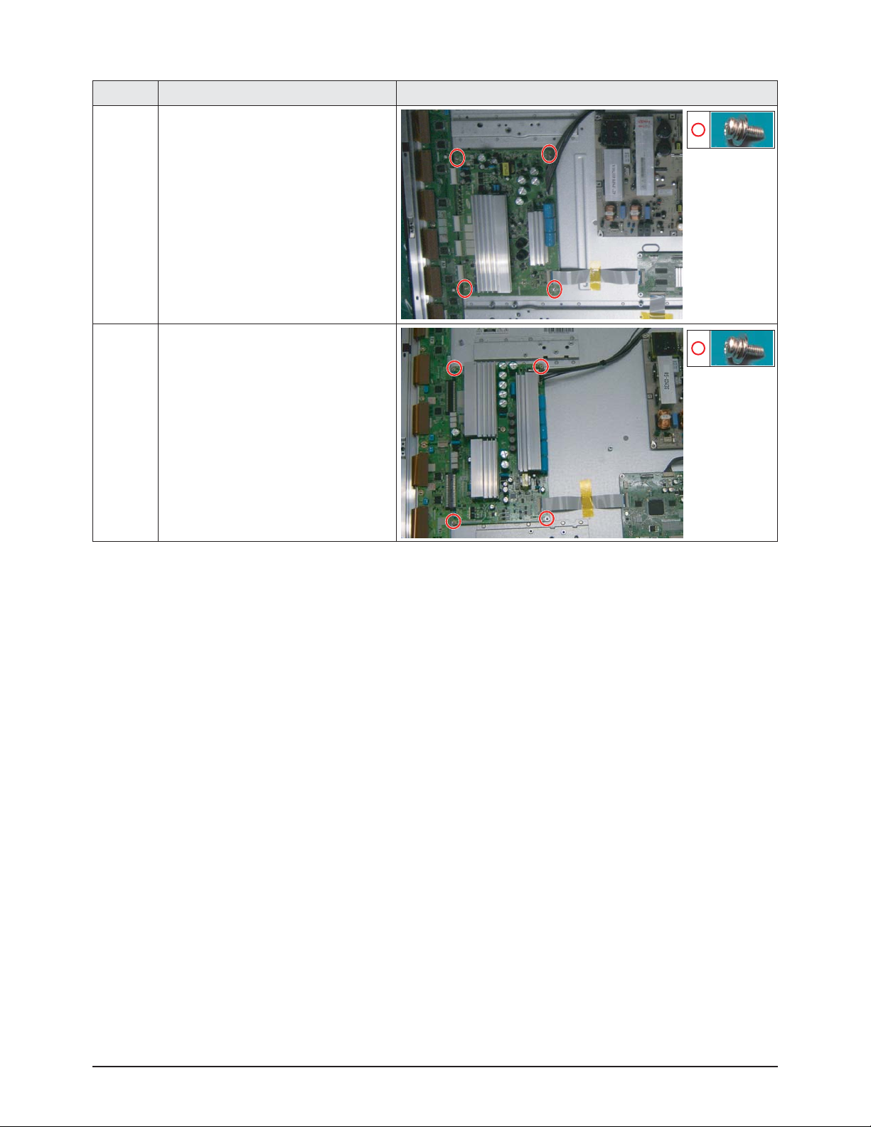
3-1-12 Separation of ASSY PDP MODULE P-X MAIN BOARD
Part Name Description Description Photo
Flat Cable
42"
X-Main
Board
① Remove 4 screws.
: PH,+,WWP,M3,L8,NI PLT
② Remove the X-Main Board.
50"
X-Main
Board
① Remove 4 screws.
: PH,+,WWP,M3,L8,NI PLT
② Remove the X-Main Board.
① Detach all Connectors from the X-Main
Board.
※ To separate the Flat Cable of the
X-Board, press the upper and the lower
sides of the connector.
Disassembly & Reassembly
Samsung Electronics 3-9
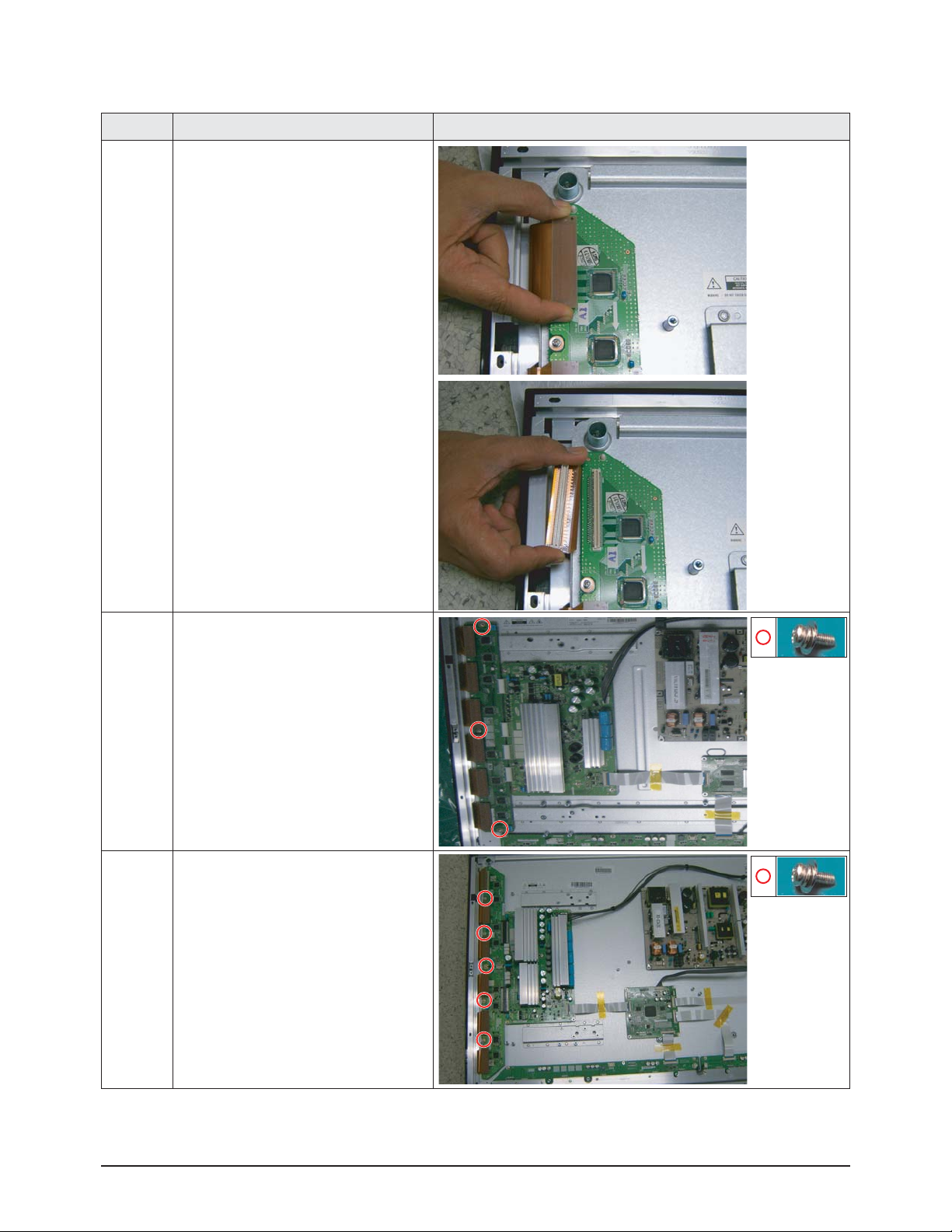
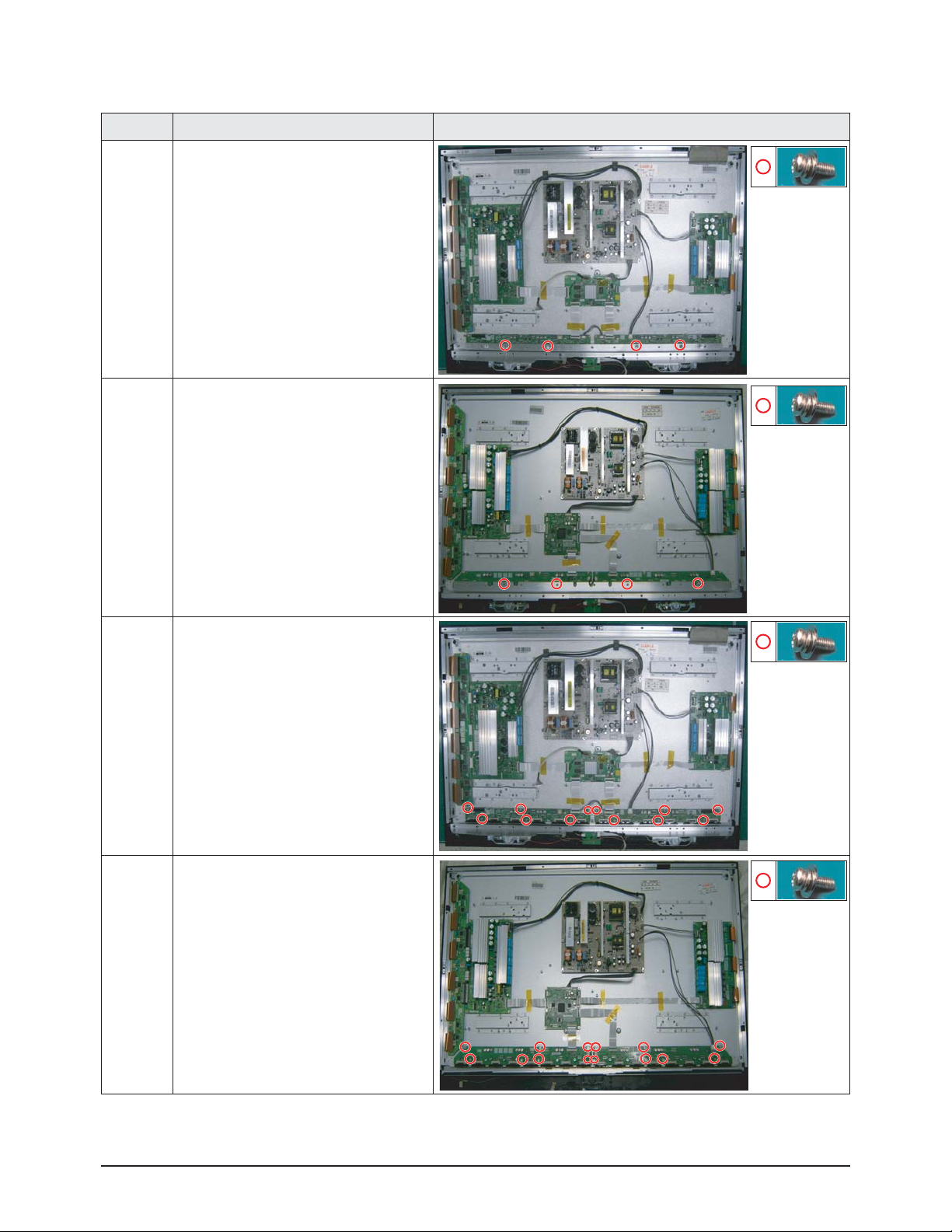
3-1-13 Separation of ASSY PDP MODULE P-Y MAIN BOARD
Part Name Description Description Photo
Flat Cable
① Detach the 6 scan board connectors
from the panel by pulling the holder from
both the top and bottom ends.
42"
Y-Scan
Board
① Remove 3 screws.
: PH,+,WWP,M3,L8,NI PLT
50"
Y-Scan
Board
① Remove 5 screws.
: PH,+,WWP,M3,L8,NI PLT
Disassembly & Reassembly
3-10 Samsung Electronics
Part Name Description Description Photo
42"
Y-Main
Board
① Remove 4 screws.
: PH,+,WWP,M3,L8,NI PLT
② Detach all connectors from the Y-Main
Board.
50"
Y-Main
Board
① Remove 4 screws.
: PH,+,WWP,M3,L8,NI PLT
② Detach all connectors from the Y-Main
Board.
Disassembly & Reassembly
Samsung Electronics 3-11
3-1-14 Separation of ASSY PDP MODULE P-ADDRESS BUFFER BOARD
Part Name Description Description Photo
42"
Still Bar
50"
Still Bar
42"
Buffer
Board
① Detach the all connectors from the
buffer board.
② Remove 3 screws.
: PH,+,WWP,M3,L8,NI PLT
③ Remove the E-Board and F-Board.
50"
Buffer
Board
① Detach the all connectors from the
buffer board.
② Remove 14 screws.
: PH,+,WWP,M3,L8,NI PLT
③ Remove the E-Board and F-Board.
① Remove 4 screws.
: PH,+,WWP,M3,L8,NI PLT
② Remove the Still Bar.
① Remove 4 screws.
: PH,+,WWP,M3,L8,NI PLT
② Remove the Still Bar.
 Loading...