


LCD-TV
Chassis GTU40MUS
GTU46MUS
Model LNT4061F
LNT4661F
SERVICE Manual
|
|
|
|
|
LCD TV |
|
Fashion Feature |
||
|
|
- Digital-TV, RF, 3-HDMI, 2-Component, 2-A/V, |
||
|
|
|
2-S-Video, USB2.0(WISELINK), D-SUB |
|
|
|
- Brightness : 500cd/m2 |
||
- |
Contrast Ratio : 8000:1 |
|||
- |
Response time : 8ms |
|||
- |
Dynamic contrast, Super-PVA |
|||
- |
PIP( in HDMI1.2.3, Component1.2, PC Mode |
|||
|
|
|
and Sub picture is available only in |
|
|
|
|
TV anolog mode.) |
|

Copyright
©2007 by Samsung Electronics Co., Ltd. All rights reserved.
This manual may not, in whole or in part, be copied, photocopied, reproduced, translated, or converted to any electronic or machine readable form without prior written permission of Samsung Electronics Co., Ltd.
LNT4061F / LNT4661F Service Manual
First edition June 2007.
Printed in Korea.
Trademarks
Samsung is the registered trademark of Samsung Electronics Co., Ltd.
LNT4061F / LNT4661F and MacMaster Cable Adapter are trademarks of Samsung Electronics Co., Ltd.
Macintosh, Power Macintosh are trademarks of Apple Computer, Inc.
All other trademarks are the property of their respective owners.
ii

Contents
1.Precautions………………………………………………………………………………………………………………………………………1-1 1-1 Safety Precautions ……………………………………………………………………………………………………………………… 1-1 1-2 Servicing Precautions …………………………………………………………………………………………………………………… 1-2 1-3 Electrostatically Sensitive Devices (ESD) Precautions ……………………………………………………………………………… 1-2
1-4 Installation Precautions ………………………………………………………………………………………………………………… 1-3
2. Product specifications …………………………………………………………………………………………………………………………2-1
2-1 Fashion Feature…………………………………………………………………………………………………………………………… 2-1
2-2 LNT4061F Specifications ………………………………………………………………………………………………………………… 2-2
2-3 LNT4661F Specifications ………………………………………………………………………………………………………………… 2-3
2-4 Option Specification ……………………………………………………………………………………………………………………… 2-4
3. Alignments and Adjustments …………………………………………………………………………………………………………………3-1 3-1 General Alignment Instuction …………………………………………………………………………………………………………… 3-1 3-2 Factory Mode Adjustments ……………………………………………………………………………………………………………… 3-2 3-3 White Balance - Calibration ……………………………………………………………………………………………………………… 3-8 3-4 White Ratio (Balance) Adjustment ……………………………………………………………………………………………………… 3-9 3-5 Servicing Information …………………………………………………………………………………………………………………… 3-10
4. Trouble shooting ………………………………………………………………………………………………………………………………4-1
4-1 No Power ………………………………………………………………………………………………………………………………… 4-1 4-2 No Video (Analog PC Signal) …………………………………………………………………………………………………………… 4-2 4-3 No Video (HDMI - Digital Signal) ……………………………………………………………………………………………………… 4-4 4-4 No Picture (Tuner_CVBS) ……………………………………………………………………………………………………………… 4-6 4-5 No Picture (Tuner DTV TS) ……………………………………………………………………………………………………………… 4-8 4-6 No Picture(Video CVBS) ……………………………………………………………………………………………………………… 4-10 4-7 No Picture(S-Video 1,2) ………………………………………………………………………………………………………………… 4-12 4-8 No Picture(Component1, 2 : 480i, 480p, 720p, 1080i[ Y, Pb, Pr] ) ……………………………………………………………… 4-14 4-9 No Sound ………………………………………………………………………………………………………………………………… 4-16
5. Exploded View and Parts List ………………………………………………………………………………………………………………5-1 5-1 LNT4061F Exploded View ……………………………………………………………………………………………………………… 5-1 5-2 LNT4061F Parts List ……………………………………………………………………………………………………………………… 5-2 5-3 LNT4661F Exploded View ……………………………………………………………………………………………………………… 5-3 5-4 LNT4661F Parts List ……………………………………………………………………………………………………………………… 5-4
6. Electrical Parts List ……………………………………………………………………………………………………………………………6-1
6-1 LNT4061F Parts List ………………………………………………………………………………………………………………………6-1
6-2 LNT4661F Parts List ……………………………………………………………………………………………………………………6-30

Contents
7.Block Diagram …………………………………………………………………………………………………………………………………7-1 7-1 Block Diagram …………………………………………………………………………………………………………………………… 7-1
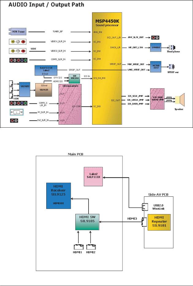
7-2 Audio Block Diagram …………………………………………………………………………………………………………………… 7-2
8. Wiring Diagram …………………………………………………………………………………………………………………………………8-1
9.Schematic Diagrams ……………………………………………………………………………………………………………………………9-1
10.Operating Instructions and Installation………………………………………………………………………………………………………10-1 10-1 Front …………………………………………………………………………………………………………………………………… 10-1 10-2 Viewing the Connection Panel ……………………………………………………………………………………………………… 10-2
10-3 Remote Control ………………………………………………………………………………………………………………………… 10-3
11. Disassembly and Reassembly ………………………………………………………………………………………………………………11-1 11-1 Disassembly …………………………………………………………………………………………………………………………… 11-1 11-2 Reassembly …………………………………………………………………………………………………………………………… 11-6
12. Schematic Diagram …………………………………………………………………………………………………………………………12-1 12-1 LNT4061F MAIN PCB Diagram ……………………………………………………………………………………………………… 12-1 12-2 LNT4661F MAIN PCB Diagram ……………………………………………………………………………………………………… 12-2 12-3 IP BOARD Diagram 40" ……………………………………………………………………………………………………………… 12-3 12-4 IP BOARD Diagram 46" ……………………………………………………………………………………………………………… 12-4
13. Circuit Descriptions …………………………………………………………………………………………………………………………13-1 13-1 Power Signal Flow …………………………………………………………………………………………………………………… 13-1 13-2 Block description ……………………………………………………………………………………………………………………… 13-2 13-3 Part Block description ………………………………………………………………………………………………………………… 13-3 13-4 IP BOARD Block diagram …………………………………………………………………………………………………………… 13-5
14. Reference Infomation ……………………………………………………………………………………………………………………… 14-1
14-1 Timing Diagram ………………………………………………………………………………………………………………………… 14-1
14-2 Technical Terms ……………………………………………………………………………………………………………………… 14-3
14-3 Pin Assignments ……………………………………………………………………………………………………………………… 14-6
14-4 Panel Description ……………………………………………………………………………………………………………………… 14-7
-This Service Manual is a property of Samsung Electronics Co., Ltd.
Any unauthorized use of Manual can be punished under applicable International and/or domestic law.
Samsung Electronics Co.,Ltd.
416, Maetan-3Dong, Yeongtong-Gu, Suwon City, Gyeonggi-Do, Korea, 443-742
Printed in Korea
P/N : BN82-00194A-00
URL : http://itself.sec.samsung.co.kr/
1 Precautions
1 Precautions
Follow these safety, servicing and ESD precautions to prevent damage and to protect against potential hazards such as electrical shock.
1-1 Safety Precautions
1-1-1 Warnings
1.For continued safety, do not attempt to modify the circuit board.
2.Disconnect the AC power and DC power jack before servicing.
1-1-2 Servicing the LCD Monitor
1.When servicing the LCD Monitor, Disconnect the AC line cord from the AC outlet.
2.It is essential that service technicians have an accurate voltage meter available at all times. Check the calibration of this meter periodically.
1-1-3 Fire and Shock Hazard
Before returning the monitor to the user, perform the following safety checks:
1.Inspect each lead dress to make certain that the leads are not pinched or that hardware is not lodged between the chassis and other metal parts in the monitor.
2.Inspect all protective devices such as nonmetallic control knobs, insulating materials, cabinet backs, adjustment and compartment covers or shields, isolation resistorcapacitor networks, mechanical insulators, etc.
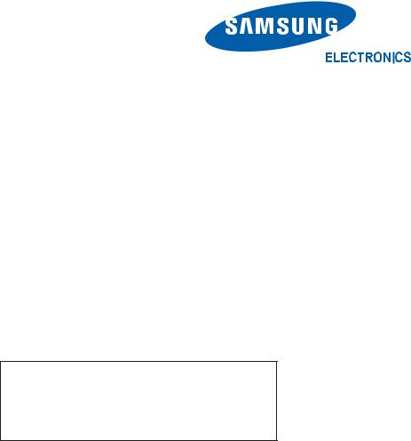
3.Leakage Current Hot Check (Figure 1-1):
WARNING : Do not use an isolation transformer during this test.
Use a leakage current tester or a metering system that complies with American National Standards Institute (ANSI C101.1, Leakage Current for Appliances), and Underwriters Laboratories (UL Publication UL1410, 59.7).
Figure 1-1. Leakage Current Test Circuit
4.With the unit completely reassembled, plug the AC line cord directly into a 120V AC outlet. With the unit’s AC switch first in the ON position and then OFF, measure the current between a known earth ground (metal water pipe, conduit, etc.) and all exposed metal parts, including: metal cabinets, screwheads and control shafts. The current measured should not exceed 0.5 milliamp. Reverse the power-plug prongs in the AC outlet and repeat the test.
1-1-4 Product Safety Notices
Some electrical and mechanical parts have special safetyrelated characteristics which are often not evident from visual inspection. The protection they give may not be obtained by replacing them with components rated for higher voltage, wattage, etc. Parts that have special safety characteristics are identified by  on schematics and parts lists. A substitute replacement that does not have the same safety characteristics as the recommended replacement part might create shock, fire and/or other hazards. Product safety is under review continuously and new instructions are issued whenever appropriate.
1-1

1 Precautions
1-2 Servicing Precautions
WARNING: An electrolytic capacitor installed with the wrong polarity might explode.
Caution: Before servicing units covered by this service manual, read and follow the Safety Precautions section of this manual.
Note: If unforeseen circumstances create conflict between the following servicing precautions and any of the safety precautions, always follow the safety precautions.
1-2-1 General Servicing
Precautions
1.Always unplug the unit’s AC power cord from the AC power source and disconnect the DC Power Jack before attempting to:
(a) remove or reinstall any component or assembly, (b) disconnect PCB plugs or connectors, (c) connect a test component in parallel with an electrolytic capacitor.
2.Some components are raised above the printed circuit board for safety. An insulation tube or tape is sometimes used. The internal wiring is sometimes clamped to prevent contact with thermally hot components. Reinstall all such elements to their original position.
3.After servicing, always check that the screws, components and wiring have been correctly reinstalled. Make sure that the area around the serviced part has not been damaged.
4.Check the insulation between the blades of the AC plug and accessible conductive parts (examples: metal panels, input terminals and earphone jacks).
5.Insulation Checking Procedure: Disconnect the power cord from the AC source and turn the power switch ON. Connect an insulation resistance meter (500 V) to the blades of the AC plug.
The insulation resistance between each blade of the AC plug and accessible conductive parts (see above) should be greater than 1 megohm.
6.Always connect a test instrument’s ground lead to the instrument chassis ground before connecting the positive lead; always remove the instrument’s ground lead last.
1-3 Electrostatically Sensitive Devices (ESD) Precautions
Some semiconductor (solid state) devices can be easily damaged by static electricity. Such components are commonly called Electrostatically Sensitive Devices (ESD). Examples of typical ESD are integrated circuits and some field-effect transistors. The following techniques will reduce the incidence of component damage caused by static electricity.
1.Immediately before handling any semiconductor components or assemblies, drain the electrostatic charge from your body by touching a known earth ground. Alternatively, wear a discharging wrist-strap device. To avoid a shock hazard, be sure to remove the wrist strap before applying power to the monitor.
2.After removing an ESD-equipped assembly, place it on a conductive surface such as aluminum foil to prevent accumulation of an electrostatic charge.
3.Do not use freon-propelled chemicals. These can generate electrical charges sufficient to damage ESDs.
4.Use only a grounded-tip soldering iron to solder or desolder ESDs.
5.Use only an anti-static solder removal device. Some solder removal devices not classified as “anti-static” can generate electrical charges sufficient to damage ESDs.
6.Do not remove a replacement ESD from its protective package until you are ready to install it. Most replacement ESDs are packaged with leads that are electrically shorted together by conductive foam, aluminum foil or other conductive materials.
7.Immediately before removing the protective material from the leads of a replacement ESD, touch the protective material to the chassis or circuit assembly into which the device will be installed.
Caution: Be sure no power is applied to the chassis or circuit and observe all other safety precautions.
8.Minimize body motions when handling unpackaged replacement ESDs. Motions such as brushing clothes together, or lifting your foot from a carpeted floor can generate enough static electricity to damage an ESD.
1-2

1 Precautions
1-4 Installation Precautions
1.For safety reasons, more than two people are required for carrying the product.
2.Keep the power cord away from any heat emitting devices, as a melted covering may cause fire or electric shock.
3.Do not place the product in areas with poor ventilation such as a bookshelf or closet. The increased internal temperature may cause fire.
4.Bend the external antenna cable when connecting it to the product. This is a measure to protect it from being exposed to moisture. Otherwise, it may cause a fire or electric shock.
5.Make sure to turn the power off and unplug the power cord from the outlet before repositioning the product. Also check the antenna cable or the external connectors if they are fully unplugged. Damage to the cord may cause fire or electric shock.
6.Keep the antenna far away from any high-voltage cables and install it firmly. Contact with the highvoltage cable or the antenna falling over may
cause fire or electric shock.
7.When installing the product, leave enough space (10cm) between the product and the wall for ventilation purposes.
A rise in temperature within the product may cause fire.
1-3

1 Precautions
Memo
1-4

2 Product Specifications
2 Product Specifications
2-1 Fashion Feature
-Digital-TV, RF, 3-HDMI, 2-Component, 2-A/V, 2-S-Video, USB2.0(WISELINK), D-SUB
-Brightness : 500cd/m2
-Contrast Ratio : 8000:1
-Response time : 8ms
-Dynamic contrast, Super PVA
-PIP( in HDMI1.2.3, Component1.2, PC Mode and Sub picture is available only in TV anolog mode.)
2-1
2 Product Specifications
2-2 LNT4061F Specifications
Item |
|
|
Description |
|
|
|
|||
LCD Panel |
TFT-LCD panel, RGB vertical stripe, SPVA mode, normally black, 40-Inch |
|||
|
viewable, 0.46125(H) x 0.15375(W)*3 mm pixel pitch |
|||
|
|
|
|
|
Scanning Frequency |
Horizontal : 30kHz~80kHz (Automatic) |
|
||
|
Vertical |
: 56Hz~75Hz (Automatic) |
|
|
|
|
|
|
|
Display Colors |
16.7 million colors |
|
||
|
|
|
|
|
Maximum Resolution |
Horizontal : 1920 Pixels |
|
||
|
Vertical |
: 1080 Pixels |
|
|
|
|
|
|
|
Input Video Signal |
H/V Separate, TTL, P. or N. |
|
||
|
|
|
||
Input Sync Signal |
Analog 0.7 Vp-p +/- 5% positive at 75 ohm,internally terminated |
|||
|
|
|
|
|
Maximum Pixel Clock rate |
160MHz |
|
||
Active Display |
34.87 x 19.6 inches (885.6 x 498.15 mm) |
|
||
Horizontal/Vertical |
|
|||
|
|
|
|
|
AC power voltage & Frequency |
AC 110V~220V, 60 Hz |
|
||
|
|
|
|
|
Power Consumption |
<245W ( < 1W, stand by ) |
|
||
|
|
|
|
|
Dimensions(W x D x H) |
|
|
|
|
Set |
38.25 x 3.425 x 25.9 inches (971.5 x 87 x 658.5 mm) without stand |
|||
|
38.25 x 11.8 x 27 inches (971.0 x 300 x 687 mm) with stand |
|||
|
|
|
|
|
Weight |
|
|
|
|
Set (With stand) |
46.5 lbs (21.1kg) |
|
||
|
|
|
||
Environmental Considerations |
Operating Temperature : 50 °F ~ 104 °F (10 °C ~ 40 °C) |
|||
|
Operating Humidity : 10 % ~ 80 % |
|
||
|
Storage Temperature : -4 °F ~ 113 °F (-20 °C ~ 45 °C) |
|||
|
Storage Humidity : 5 % ~ 95 % |
|
||
|
|
|
|
|
TV System |
|
Tuning |
|
Frequency Synthesize |
|
System |
|
ATSC, NTSC5.38 |
|
|
|
|
||
|
|
Sound |
|
NTSC-M, AC-3 Digital |
Antenna Input |
75Ω |
|
|
|
|
|
|
||
Sound Characteristic |
- MAX Internal speaker Out : Right => 10W, Left => 10W |
|||
|
- BASS Control Range : -8 dB ~ + 8dB |
|
||
|
- TREBLE Control Range : -8 dB ~ +8 dB |
|
||
|
- Headphone Out : 10 mW MAX |
|
||
|
- Output Frequency : RF : 80 Hz ~ 15 kHz |
|||
|
|
A/V : 80 Hz ~ 20 kHz |
||
|
|
|
|
|
2-2

2 Product Specifications
2-3 LNT4661F Specifications
Item |
|
|
Description |
|
|
||
LCD Panel |
TFT-LCD panel, RGB vertical stripe, SPVA mode, normally black, 46-Inch |
||
|
viewable, 0.53025(H) x 0.17675(W)*3 mm pixel pitch |
||
|
|
|
|
Scanning Frequency |
Horizontal : 30kHz~80kHz (Automatic) |
||
|
Vertical |
: 56Hz~75Hz (Automatic) |
|
|
|
|
|
Display Colors |
16.7 million colors |
|
|
|
|
|
|
Maximum Resolution |
Horizontal : 1920 Pixels |
|
|
|
Vertical |
: 1080 Pixels |
|
|
|
|
|
Input Video Signal |
H/V Separate, TTL, P. or N. |
||
|
|
|
|
Input Sync Signal |
Analog 0.7 Vp-p +/- 5% positive at 75 ohm,internally terminated |
||
|
|
|
|
Maximum Pixel Clock rate |
165MHz |
|
|
Active Display |
40.1 x 22.7 inches(1018.08 x 576.67 mm) |
||
Horizontal/Vertical |
|||
|
|
|
|
AC power voltage & Frequency |
AC 110V~220V, 60 Hz |
|
|
|
|
|
|
Power Consumption |
<265W ( < 1W, stand by ) |
|
|
|
|
|
|
Dimensions(W x D x H) |
|
|
|
Set |
43.55 x 4.1 x 27.8 inches (1106.3 x 104.2 x 706.2 mm) without stand |
||
|
43.55 x 12.8 x 30.2 inches (1106.3 x 326 x 768 mm) with stand |
||
|
|
|
|
Weight |
|
|
|
Set (With stand) |
65.25 lbs(29.6kg) |
|
|
|
|
|
|
Environmental Considerations |
Operating Temperature : |
50 °F ~ 104 °F (10 °C ~ 40 °C) |
|
|
Operating Humidity : 10 % ~ 80 % |
||
|
Storage Temperature : -4 °F ~ 113 °F (-20 °C ~ 45 °C) |
||
|
Storage Humidity : 5 % ~ 95 % |
||
|
|
|
|
TV System |
|
Tuning |
Frequency Synthesize |
|
|
|
|
|
System |
ATSC, NTSC5.38 |
|
|
|
||
|
|
Sound |
NTSC-M, AC-3 Digital |
Antenna Input |
75Ω |
|
|
|
|
|
|
Sound Characteristic |
- MAX Internal speaker Out : Right => 10W, Left => 10W |
||
|
- BASS Control Range : -8 dB ~ + 8dB |
||
|
- TREBLE Control Range : -8 dB ~ +8 dB |
||
|
- Headphone Out : 10 mW MAX |
||
|
- Output Frequency : RF : 80 Hz ~ 15 kHz |
||
|
|
A/V : 80 Hz ~ 20 kHz |
|
|
|
|
|
2-3
2 Product Specifications
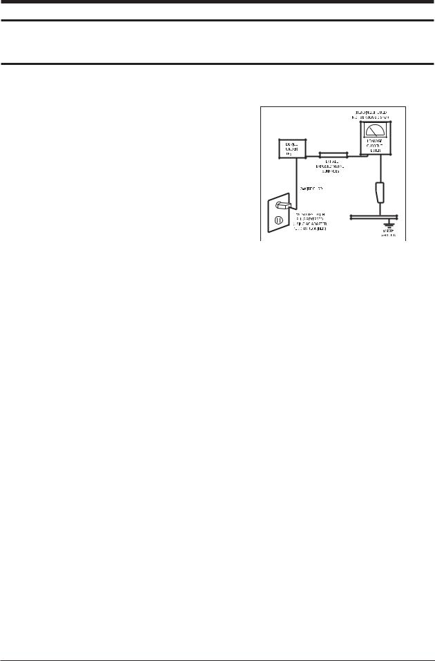
2-4 Option Specification
Item |
Item Name |
Code.No |
Remark |
|
Remote Control & |
BN59-00599A |
|
|
Batteries (AAA x 2) |
|
|
|
|
|
Power Cord |
3903-000144 |
Cover-Bottom BN63-03103B
Stand |
40" : BN96-04640A |
|
46" : BN96-04648A |
||
|
Stand Screw (4 ea) |
6002-001294 |
Owner's Instructions |
BN68-01178A |
Cleaning Cloth |
BN63-01798A |
Warranty Card /
Registration
Card /Safety Guide Manual 6801-001011
(Not available in all locations)
2-4

3 Alignments and Adjustments
3 Alignments and Adjustments
3-1 General Alignment Instuction
1.Usually, a color LCD-TV needs only slight touch-up adjustment upon installation. Check the basic characteristics such as height, horizontal and vertical sync.
2.Use the specified test equipment or its equivalent.
3.Correct impedance matching is essential.
4.Avoid overload. Excessive signal from a sweep generator might overload the front-end
of the TV. When inserting signal markers, do not allow the marker generator to distort test result.
5.Connect the TV only to an AC power source with voltage and frequency as specified on the backcover nameplate.
6.Do not attempt to connect or disconnect any wire while the TV is turned on. Make sure that the power cord is disconnected before replacing any parts.
7.To protect against shock hazard, use an isolation transformer.
3-1

3 Alignments and Adjustments
3-2 Factory Mode Adjustments
3-2-1 Entering Factory Mode
To enter 'Service Mode' Press the remote -control keys in this sequence : - If you do not have Factory remote - control
Power OFF |
|
|
|
MUTE |
|
|
|
1 |
|
|
|
8 |
|
|
|
2 |
|
|
|
Power On |
|
|
|
|
|
|
|
|
|
|
|
|
|||||||||
|
|
|
|
|
|
|
|
|
|
|
|
|
|
|
|
|
|
|
|
|
3-2-2 How to Access Service Mode
 Using the Customer Remote
1.Turn the power off and set to stand-by mode
2.Press the remote buttons in this order; POWER OFF-MUTE-1-8-2-POWER ON to turn the set on. 3.The set turns on and enters service mode. This may take approximately 20 seconds.
4.Press the Power button to exit and store data in memory.
 If you fail to enter service mode, repeat steps 1 and 2 above. 5.Initial SERVICE MODE DISPLAY State
|
|
|
NTSC-RF |
|
|
|
|
|
||
|
Calibration |
|
Submicom Download |
|
|
|
|
|
||
|
Option Byte |
|
Checksum |
|
|
|
|
|
||
|
White Balance |
|
KS1410 |
|
|
|
|
|
||
|
W/B MOVIE |
|
Dynamic Contrast |
|
|
|
|
|
||
|
SVP-LX |
|
EEPROM Access Count |
|
|
|
|
|
||
|
FBE2 |
|
RESET |
|
|
|
|
|
||
|
MSP44XX |
|
|
|
|
|
|
|
|
|
|
NTP3000 |
|
|
|
|
|
|
|
|
|
|
T-TULPAUS0_0040 Jan 31 2007 |
|
|
|
|
|
||||
|
T-TULPAUS5_C004 [Sec : 08] |
|
|
|
|
|
||||
|
|
|
|
|
|
|
|
|
||
|
"T-TULPUS0-0025" and "T-TULPAUS5-C007" are firmware....... |
|
|
|||||||
|
|
|
|
|
|
|
|
|
|
|
|
|
|
|
|
|
|
|
|
|
|
6. Buttons operations withn Service Mode |
|
|
|
|
|
|||||
|
|
|
|
|
|
|
|
|
|
|
|
Menu |
|
|
Full Menu Display/Move to Parent Menu |
|
|
||||
Direction Keys |
|
|
Item Selection by Moving the Cursor |
|
|
|||||
|
|
|
|
|
|
|
|
|
||
Direction Keys |
|
|
Data Increase / Decrease for the Selected Item |
|
|
|||||
|
|
|
|
|
|
|
|
|
|
|
|
Source |
|
|
Cycles through the active input source that are connected to the unit |
|
|
||||
|
|
|
|
|
|
|
|
|
||
3-2-3 Factory Data |
|
|
|
|
|
|||||
|
|
|
|
|
|
|
|
|
|
|
|
|
NTSC-RF |
|
|
|
|
|
|
||
|
|
Submicom Download |
|
|
|
|
|
|
||
Calibration |
|
|
|
|
|
|
|
|||
|
|
|
|
|
|
|
|
|
||
Option Byte |
|
Checksum |
|
|
|
|
|
|
||
White Balance |
|
KS1410 |
|
|
|
|
|
|
||
W/B MOVIE |
|
Dynamic Contrast |
|
|
|
|
|
|
||
SVP-LX |
|
EEPROM Access Count |
|
|
|
|
|
|
||
FBE2 |
|
RESET |
|
|
|
|
|
|
||
MSP44XX |
|
|
|
|
|
AV Calibration |
|
|
|
|
|
|
|
|
|
Comp Calibration |
|
|
|
||
NTP3000 |
|
|
|
|
|
|
|
|
||
|
|
|
|
|
PC Calibration |
|
|
|
||
|
T-TULPAUS0_0040 Jan 31 2007 |
|
|
|
|
|
||||
|
T-TULPAUS5_C004 [Sec : 08] |
|
|
HDMI Calibration |
|
|
|
|||
3-2

3 Alignments and Adjustments
|
NTSC-RF |
|
Calibration |
|
Submicom Download |
|
|
Checksum |
Option Byte |
|
|
White Balance |
|
KS1410 |
W/B MOVIE |
|
Dynamic Contrast |
SVP-LX |
|
EEPROM Access Count |
FBE2 |
|
RESET |
MSP44XX
NTP3000
T-TULPAUS0_0040 Jan 31 2007
T-TULPAUS5_C004 [Sec : 08]
|
NTSC-RF |
|
Calibration |
|
Submicom Download |
Option Byte |
|
Checksum |
|
|
|
White Balance |
|
KS1410 |
W/B MOVIE |
|
Dynamic Contrast |
SVP-LX |
|
EEPROM Access Count |
FBE2 |
|
RESET |
MSP44XX |
|
|
NTP3000
T-TULPAUS0_0040 Jan 31 2007
T-TULPAUS5_C004 [Sec : 08]
|
NTSC-RF |
|
Calibration |
|
Submicom Download |
Option Byte |
|
Checksum |
White Balance |
|
KS1410 |
|
|
|
W/B MOVIE |
|
Dynamic Contrast |
SVP-LX |
|
EEPROM Access Count |
FBE2 |
|
RESET |
MSP44XX |
|
|
NTP3000
T-TULPAUS0_0040 Jan 31 2007
T-TULPAUS5_C004 [Sec : 08]
|
|
Caption Level |
10 |
|
|
Panel Display Time |
16 |
|
|
|
Watchdog Enable |
1 |
|
|
Mute Time[RF] |
Off |
|
|
|
Spread Spectrum |
>> |
|
|
CH Memory |
Off |
|
|
|
MODEL |
Tulip |
|
|
shop mode |
|
|
|
|
Panel Option |
None |
|
|
Downloadable RRT |
|
|
|
|
PWM Dimming |
INT |
|
|
PC Mode ident |
|
|
|
|
NIM Version |
KS1410 |
|
|
IRE |
|
|
|
|
AUTO WALL |
On |
|
|
IRE Offset |
|
|
|
|
RS-232 JACK |
AutoWM |
|
|
HDMI Hot plug |
|
|
|
|
Gamma |
OFF |
|
|
HDMI Delay Time |
|
|
|
|
HSCB |
STD |
|
|
HDMI Mode Ident |
|
|
|
|
LVDS_TX_Fmt |
[2] |
|
|
Select FBE |
|
|
|
|
LVDS_TX_Bit |
10Bit |
|
|
WM_Calibration |
|
|
|
|
|
|
|
|
SVP Caption level |
|
|
|
|
|
|
|
|
No MGT Case Enable |
|
|
|
|
|
|
|
|
Hotel Mode |
|
|
|
|
|
|
|
|
|
|
|
|
|
|
|
|
|
|
|
|
|
|
Sub Brightness |
128 |
|
|
|
|
|
|
|
R-Offset |
512 |
|
|
|
|
|
|
|
G-Offset |
512 |
|
|
|
|
|
|
|
B-Offset |
512 |
|
|
|
|
|
|
|
Sub Contrast |
128 |
|
|
|
|
|
|
|
R-Gain |
512 |
|
|
|
|
|
|
|
G-Gain |
512 |
|
|
|
|
|
|
|
B-Gain |
512 |
|
|
|
|
|
|
|
|
|
|
|
|
|
|
|
|
|
|
|
|
|
|
|
|
W/B MOVIE ON/OFF |
Off |
|
|
|
Nor_Rgain |
0 |
|
|
MODE |
Dynamic |
|
|
|
Nor_Bgain |
0 |
|
|
Color Tone |
Cool1 |
|
|
|
Nor_Roffset |
0 |
|
|
Msub Contrast |
128 |
|
|
|
Nor_Boffset |
0 |
|
|
Msub Bright |
128 |
|
|
|
C2_Rgain |
0 |
|
|
W1_Rgain |
0 |
|
|
|
C2_Bgain |
0 |
|
|
W1_Bgain |
0 |
|
|
|
C2_Roffset |
0 |
|
|
W1_Roffset |
0 |
|
|
|
C2_Boffset |
0 |
|
|
W1_Boffset |
0 |
|
|
|
Movie Contrast |
80 |
|
|
W2_Rgain |
0 |
|
|
|
Movie Bright |
50 |
|
|
W2_Bgain |
0 |
|
|
|
Movie Color |
55 |
|
|
W2_Roffset |
0 |
|
|
|
Movie Sharpness |
20 |
|
|
W2_Boffset |
0 |
|
|
|
|
|
|
|
|
|
|
|
|
|
|
|
3-3

3 Alignments and Adjustments
|
NTSC-RF |
|
Calibration |
|
Submicom Download |
Option Byte |
|
Checksum |
White Balance |
|
KS1410 |
W/B MOVIE |
|
Dynamic Contrast |
|
|
|
SVP-LX |
|
EEPROM Access Count |
FBE2 |
|
RESET |
MSP44XX |
|
|
NTP3000
T-TULPAUS0_0040 Jan 31 2007
T-TULPAUS5_C004 [Sec : 08]
|
|
|
Sharpness |
>> |
|
LNA PLUS |
>> |
|
UV Delay |
>> |
|
PGA |
>> |
|
Calibration Target |
>> |
|
CLK_A |
16 |
|
CLK_B |
133 |
|
CLK_C |
8 |
|
Roffset |
67 |
|
Goffset |
67 |
|
Boffset |
67 |
|
RGain |
274 |
|
GGain |
274 |
|
BGain |
274 |
|
|
|
|
|
|
|
Sharpness |
>> |
|
|
|
|
LNA PLUS |
>> |
|
|
|
|
UV Delay |
>> |
|
PGA |
>> |
|
Calibration Target |
>> |
|
CLK_A |
16 |
|
CLK_B |
133 |
|
CLK_C |
8 |
|
Roffset |
67 |
|
Goffset |
67 |
|
Boffset |
67 |
|
RGain |
274 |
|
GGain |
274 |
|
BGain |
274 |
|
|
|
|
|
|
|
Sharpness |
>> |
|
LNA PLUS |
>> |
|
UV Delay |
>> |
|
PGA |
>> |
|
Calibration Target |
>> |
|
CLK_A |
16 |
|
CLK_B |
133 |
|
CLK_C |
8 |
|
Roffset |
67 |
|
Goffset |
67 |
|
Boffset |
67 |
|
RGain |
274 |
|
GGain |
274 |
|
BGain |
274 |
|
|
|
|
H2gain |
10 |
|
|
|
|
H4gain |
10 |
|
V2gain |
16 |
|
V4gain |
16 |
|
Sr2gain |
0 |
|
Sr4gain |
0 |
|
Sl2gain |
0 |
|
Sl4gain |
0 |
|
Peakth1 |
8 |
|
Peakth2 |
47 |
|
Sub_Color |
80 |
|
|
|
|
dB0_Peaking_th1 0
dB0_Vpeaking_th1 0 dB1_NoiseAmount 0 dB1_Peaking_th1 0 dB1_Vpeaking_th1 0 dB2_NoiseAmount 0 dB2_Peaking_th1 0 dB2_Vpeaking_th2 0 dB3_NoiseAmount 0 dB3_Peaking_th1 0 dB3_Vpeaking_th1 0
|
|
|
U Delay |
0 |
|
|
|
|
V Delay |
0 |
|
|
|
|
3-4

3 Alignments and Adjustments
Sharpness |
>> |
|
|
|
|
LNA PLUS |
>> |
|
|
|
|
UV Delay |
>> |
|
|
|
|
|
|
|
|
|
|
PGA |
>> |
|
|
|
|
|
|
|
|
|
|
Calibration Target |
>> |
|
|
|
|
CLK_A |
16 |
|
TCD3_Contrast |
119 |
|
CLK_B |
133 |
|
TCD3_Bright |
44 |
|
CLK_C |
8 |
|
TCD3_YC_Delay |
0 |
|
Roffset |
67 |
|
ANALOG_Y_Offset |
64 |
|
Goffset |
67 |
|
ANALOG_PB_Offset |
128 |
|
Boffset |
67 |
|
ANALOG_PR_Offset |
128 |
|
RGain |
274 |
|
ANALOG_Y_Gain |
183 |
|
GGain |
274 |
|
ANALOG_PB_Gain |
128 |
|
BGain |
274 |
|
ANALOG_PR_Gain |
128 |
|
Sharpness |
>> |
|
LNA PLUS |
>> |
|
UV Delay |
>> |
|
PGA |
>> |
|
|
|
|
Calibration Target |
>> |
|
|
|
|
CLK_A |
16 |
|
CLK_B |
133 |
|
CLK_C |
8 |
|
Roffset |
67 |
|
Goffset |
67 |
|
Boffset |
67 |
|
RGain |
274 |
|
GGain |
274 |
|
BGain |
274 |
|
|
|
|
1st_AV_LOW |
0x10 |
|
|
|
|
1st_AV_High |
0xDC |
|
1st_AV_Delta |
0x4 |
|
1st_COMP_LOW |
0x10 |
|
1st_COMP_High |
0xEB |
|
1st_COMP_Delta |
0x4 |
|
1st_PC_LOW |
0x4 |
|
1st_PC_High |
0xEB |
|
1st_PC_Delta |
0x4 |
|
NONE |
|
|
NONE |
|
|
NONE |
|
|
2st_AV_LOW |
0x1 |
|
|
|
|
0xEB
2st_AV_High 0x8 2st_AV_Delta 0x1 2st_COMP_LOW 0xEB 2st_COMP_High 0x8 2st_COMP_Delta 0x1 2st_PC_LOW 0xEB 2st_PC_High 0x8 2st_PC_Delta 0x1 2st_HDMI_LOW 0xEB 2st_HDMI_High 0x8 2st_HDMI_Delta
|
|
|
|
|
|
|
|
|
|
|
|
|
|
Patt-Sel |
0 |
|
|
Skin-Enable |
1 |
|
|
|
|
B-Slope Gain |
44 |
|
|
Skin-Tu |
120 |
|
|
|
B-Tilt Min |
20 |
|
|
Skin-Tv |
120 |
|
|
NTSC-RF |
|
|
|
|||||
Calibration |
|
Submicom Download |
|
B-Tilt Max |
120 |
|
|
Sub Color |
135 |
Option Byte |
|
Checksum |
|
Lfunc Basis |
65 |
|
|
M-Skin-Tu |
128 |
|
|
Hfunc Basis |
88 |
|
|
M-Skin-Tv |
128 |
||
White Balance |
|
KS1410 |
|
|
|
||||
|
|
Mean offset1 |
45 |
|
|
M-Au-Sub color |
128 |
||
W/B MOVIE |
|
Dynamic Contrast |
|
|
|
||||
|
|
Mean offset2 |
175 |
|
|
MW_Skin Tu |
128 |
||
SVP-LX |
|
EEPROM Access Count |
|
|
|
||||
|
|
Mean slope |
70 |
|
|
MW_Skin Tv |
128 |
||
|
|
|
|
|
|
||||
FBE2 |
|
RESET |
|
|
|
||||
|
|
Input Offset |
128 |
|
|
M-Wi-Sub color |
128 |
||
MSP44XX |
|
|
|
|
|
||||
|
|
|
Acr Offset |
15 |
|
|
|
|
|
NTP3000 |
|
|
|
|
|
|
|
||
|
|
|
Arc Th1 |
30 |
|
|
|
|
|
T-TULPAUS0_0040 Jan 31 2007 |
|
|
|
|
|
||||
|
Acr th2 |
100 |
|
|
|
|
|||
T-TULPAUS5_C004 [Sec : 08] |
|
|
|
|
|
||||
|
|
|
|
|
|
|
|
|
|
3-5

3 Alignments and Adjustments
|
NTSC-RF |
|
Calibration |
|
Submicom Download |
Option Byte |
|
Checksum |
White Balance |
|
KS1410 |
W/B MOVIE |
|
Dynamic Contrast |
SVP-LX |
|
EEPROM Access Count |
FBE2 |
|
RESET |
MSP44XX |
|
|
NTP3000
T-TULPAUS0_0040 Jan 31 2007
T-TULPAUS5_C004 [Sec : 08]
|
NTSC-RF |
Calibration |
Submicom Download |
Option Byte |
Checksum |
White Balance |
KS1410 |
W/B MOVIE |
Dynamic Contrast |
SVP-LX |
EEPROM Access Count |
FBE2 |
RESET |
MSP44XX |
|
NTP3000
T-TULPAUS0_0040 Jan 31 2007
T-TULPAUS5_C004 [Sec : 08]
|
NTSC-RF |
|
Calibration |
|
|
|
Submicom Download |
|
Option Byte |
|
|
|
Checksum |
|
White Balance |
|
KS1410 |
W/B MOVIE |
|
Dynamic Contrast |
SVP-LX |
|
EEPROM Access Count |
FBE2 |
|
RESET |
MSP44XX |
|
|
NTP3000
T-TULPAUS0_0040 Jan 31 2007
T-TULPAUS5_C004 [Sec : 08]
|
NTSC-RF |
|
Calibration |
|
Submicom Download |
Option Byte |
|
|
|
Checksum |
|
White Balance |
|
|
|
KS1410 |
|
W/B MOVIE |
|
Dynamic Contrast |
SVP-LX |
|
EEPROM Access Count |
FBE2 |
|
RESET |
MSP44XX |
|
|
NTP3000
T-TULPAUS0_0040 Jan 31 2007
T-TULPAUS5_C004 [Sec : 08]
|
FM_Precale |
31 |
|
|
NICAM_Prescale |
7 |
|
|
SpdifDely |
0 |
|
|
InternalDelayDtv |
0 |
|
|
InternalDelayAnalog |
45 |
|
|
Carrier Mute |
1 |
|
|
Pilot High |
10 |
|
|
Pilot Low |
5 |
|
|
Scart1 Out Volume |
109 |
|
|
Scart2 Out Volume |
115 |
|
|
|
|
|
|
Amp Volume |
30 |
|
|
PWM MOD |
243 |
|
|
Drc Thresh |
12 |
|
|
Speaker EQ |
1 |
|
|
|
|
|
|
|
|
Submicom Download |
0 |
|
|
|
|
|
|
|
|
|
|
Checksum |
[0000] |
|
|
|
|
|
|
|
3-6

3 Alignments and Adjustments
|
NTSC-RF |
|
Calibration |
|
Submicom Download |
Option Byte |
|
Checksum |
White Balance |
|
|
|
KS1410 |
|
W/B MOVIE |
|
|
|
Dynamic Contrast |
|
SVP-LX |
|
EEPROM Access Count |
FBE2 |
|
RESET |
MSP44XX |
|
|
NTP3000
T-TULPAUS0_0040 Jan 31 2007
T-TULPAUS5_C004 [Sec : 08]
|
NTSC-RF |
|
Calibration |
|
Submicom Download |
Option Byte |
|
Checksum |
White Balance |
|
KS1410 |
W/B MOVIE |
|
|
|
Dynamic Contrast |
|
SVP-LX |
|
EEPROM Access Count |
FBE2 |
|
RESET |
MSP44XX |
|
|
NTP3000
T-TULPAUS0_0040 Jan 31 2007
T-TULPAUS5_C004 [Sec : 08]
|
NTSC-RF |
|
Calibration |
|
Submicom Download |
Option Byte |
|
Checksum |
White Balance |
|
KS1410 |
W/B MOVIE |
|
Dynamic Contrast |
SVP-LX |
|
|
|
EEPROM Access Count |
|
FBE2 |
|
|
|
RESET |
|
MSP44XX |
|
|
NTP3000
T-TULPAUS0_0040 Jan 31 2007
T-TULPAUS5_C004 [Sec : 08]
|
NTSC-RF |
|
Calibration |
|
Submicom Download |
Option Byte |
|
Checksum |
White Balance |
|
KS1410 |
W/B MOVIE |
|
Dynamic Contrast |
SVP-LX |
|
EEPROM Access Count |
FBE2 |
|
|
|
RESET |
|
MSP44XX |
|
|
NTP3000
T-TULPAUS0_0040 Jan 31 2007
T-TULPAUS5_C004 [Sec : 08]
|
|
|
0x6111 |
RF_AGC |
0x8A |
VSB_EQ_STEP |
|
|
|
VSB_PTL_STEP |
0x522 |
VSB-CR_GAIN |
0x2E |
||
VSB-CR_K1_1_NARROW |
0xE |
VSB_PTL_ALPHA |
0x55 |
VSB-CR_K1_1_WIDE |
0xC |
QAM_AGC |
0x2A38 |
VSB-CR_K1_2_NARROW |
0xD |
QAM_EQ_STEP1 |
0x312F |
VSB-CR_K1_2_WIDE |
0xC |
QAM+EQ_STEP2 |
0xA8B0 |
VSB-CR_K2_1_NARROW |
0x12 |
QAM_PTL_K1 |
0X37 |
VSB-CR_K2_1_WIDE |
0x10 |
QAM_PTL_K2 |
0x2D |
VSB-CR_K2_2_NARROW |
0x11 |
|
|
VSB-CR_K2_2_WIDE |
0x10 |
|
|
VSB_EQ_CTRL1 |
0x30E |
|
|
VSB_EQ_CTRL2 |
0x104 |
|
|
VSB_EQ_INIT_STEP |
0x3161 |
|
|
|
|
|
|
|
|
|
|
|
|
|
|
Dynamic CE |
|
Off |
|
|
|
|
Dynamic Dimming |
|
Off |
|
|
|
|
FBE2 Y_MEAN READ |
|
|
|
|
|
|
|
|
|
|
|
|
|
|
|
|
|
||
|
Addr:2DAA, Cnt: |
4 |
Addr:329E, Cnt: |
2 |
||
|
|
|
Addr:32A0, Cnt: |
2 |
||
|
Addr:32A5, Cnt: |
2 |
||||
|
Addr:2DA8, Cnt: |
2 |
Addr:329D, Cnt: |
2 |
||
|
Addr:2D58, Cnt: |
2 |
Addr:329C, Cnt: |
2 |
||
|
Addr:2D5A, Cnt: |
2 |
Addr:329B, Cnt: |
2 |
||
|
Addr:2DA9, Cnt: |
2 |
Addr:329A, Cnt: |
2 |
||
|
Addr:2D5B, Cnt: |
2 |
Addr:3299, Cnt: |
2 |
||
|
Addr:2D59, Cnt: |
2 |
Addr:3298, Cnt: |
2 |
||
|
Addr:2DAB, Cnt: |
2 |
Addr:3297, Cnt: |
2 |
||
|
Addr:732E, Cnt: |
2 |
Addr:2581, Cnt: |
2 |
||
|
Addr:7331, Cnt: |
2 |
Addr:329F, Cnt: |
2 |
||
|
Addr:2A19, Cnt: |
2 |
|
|
|
|
|
Addr:737F, Cnt: |
2 |
|
|
|
|
|
|
|
|
|
|
|
3-7
3 Alignments and Adjustments
3-3 White Balance - Calibration
3-3-1 White Balance -Calibration
1. Calibration |
|
AV Calibration |
|
Comp Calibration
PC Calibration
HDMI Calibration
3-3-2 White Balance - Adjustment
|
|
|
|
(low light) |
(hight light) |
3. W/B |
|
|
|
Sub Bright |
Sub Contrast |
|
|
||||
|
|
|
|
R offset |
R gain |
|
|||||
|
|
|
|
G offset |
G gain |
|
|
|
|
B offset |
B gain |
|
|
|
|
|
|
|
|
|
|
|
(W/B adjustment Condition refer next page) |
3-8

3 Alignments and Adjustments
3-4 White Ratio (Balance) Adjustment
1.You can adjust the white ratio in factory mode (1:Calibration, 3:White-Balance).
2.Since the adjustment value and the data value vary depending on the input source, you have to adjust these in CVBS, Component 1 and HDMI 1 modes.
3.The optimal values for each mode are configured by default. (Refer to Table 1, 2.)
It varies with Panel's size and Specification.
-Equipment : CS-210
-Pattern: MIK K-7256 #92 "Flat W/B Pattern" as standard
-Use other equipment only after comparing the result with that of the Master equipment.
-Set Aging time : 60min 
-Calibration and Manual setting for WB adjustment.
HDMI : Calibration at #24 Chessboard Pattern  Manual adjustment #92 pattern (720p) COMP: Calibration at #24 Chessboard Pattern
  Manual adjustment at #92 pattern (720p) CVBS: Calibration at #24 Chessboard Pattern
  Manual adjustment at #92 pattern (NTSC)
-If finishing in HDMI mode, adjustment coordinate is almost same in AV/COMP mode.
-White Balance Manual Adjustment
|
|
|
|
|
|
Adjustment Coordinate |
|
|
|
|
|
|
|
|
|
|
|
|
|
|
x |
|
y |
|
Y(L) |
T(K) + MPCD |
|
|
|
|
|
|
|
|
|
|
H/L |
|
266 |
|
288 |
|
- |
12,000 (¡¾0) |
CVBS |
|
|
|
(Sub_CT:130) |
||||
|
|
|
|
|
|
|
||
(NTSC) |
L/L |
|
266 |
|
288 |
|
12.6cd/m2 |
12,000 (¡¾0) |
|
|
|
|
|||||
|
|
|
|
(3.7 Ft) |
||||
|
|
|
|
|
|
|
|
|
|
|
|
|
|
|
|
|
|
|
H/L |
|
266 |
|
288 |
|
- |
12,000 (¡¾0) |
COMP |
|
|
|
(Sub_CT:130) |
||||
|
|
|
|
|
|
|
||
|
|
|
|
|
|
|
|
|
(720P) |
L/L |
|
266 |
|
288 |
|
13.0cd/m2 |
12,000 (¡¾0) |
|
|
|
|
|||||
|
|
|
|
(3.8 Ft) |
||||
|
|
|
|
|
|
|
|
|
|
|
|
|
|
|
|
|
|
|
H/L |
|
266 |
|
288 |
|
- |
12,000 (¡¾0) |
HDMI |
|
|
|
(Sub_CT:130) |
||||
|
|
|
|
|
|
|
||
(720P) |
L/L |
|
266 |
|
288 |
|
13.0cd/m2 |
12,000 (¡¾0) |
|
|
|
|
|||||
|
|
|
|
(3.8 Ft) |
||||
|
|
|
|
|
|
|
|
|
|
|
|
|
|
|
|
|
|
- Adjustment Specification |
|
|
|
|
|
|
||
White Balance : High light ( |
2), Low light ( |
3) |
|
|
|
|||
Luminance : High light (Don't care), Low light ( 0.2 Ft/L) |
|
|||||||
3-9
3 Alignments and Adjustments
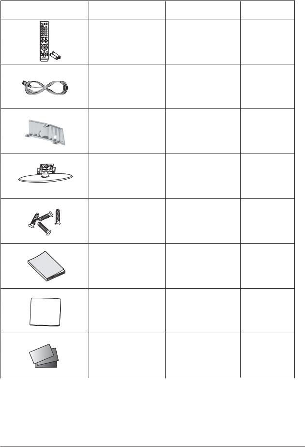
3-5 Servicing Information
3-5-1 USB Download Method
Samsung may offer upgrades for TV's firmware in the future. Please contact the Samsung call center at 1-800-SAMSUNG (7267864) to receive information about downloading upgrades and using a USB drive. Upgrades will be possible by connecting a USB drive to the USB port located on located on the back of your TV.
1.Insert a USB drive containing the firmware upgrade into the WISELINK port on the side of the TV.
2.Press the MENU button to display the menu.
Press the 
 button to select Setup, then press the ENTER button.
3.Press the  or
or  button to select Software upgrade, then press the ENTER button.
4.Press the  or
or  button to select USB Upgrade, then press the ENTER button.
The message Scanning for USB...
It may take up to 30 seconds is displayed.
Please be careful to not disconnect the power or remove the USB drive while upgrades are being applied. The TV will shut off and turn on automatically after completing the firmware upgrade. Please check the firmware version after the upgrades are complete.
* How to check Program Version
1.Press " MENU "
2.Select " SETUP "
3.Select " INFORMATION HELP "
4.Highlight " ON " option
5.Press " INFO " button on the remote control
3-10

13 Circuit Descriptions
13 Circuit Descriptions
13-1 Main Board Block Description
13-1

13 Circuit Descriptions
13-2 Video Signal Path
13-2
13 Circuit Descriptions
13-3 Audio Signal Path
13-3 Side AV Signal Path
13-3

13 Circuit Descriptions
Memo
13-4
5 Exploded View & Parts List
5 Exploded View and Parts List
-You can search for updated part codes through ITSELF web site.
URL : http://itself. sec. samsung.co.kr
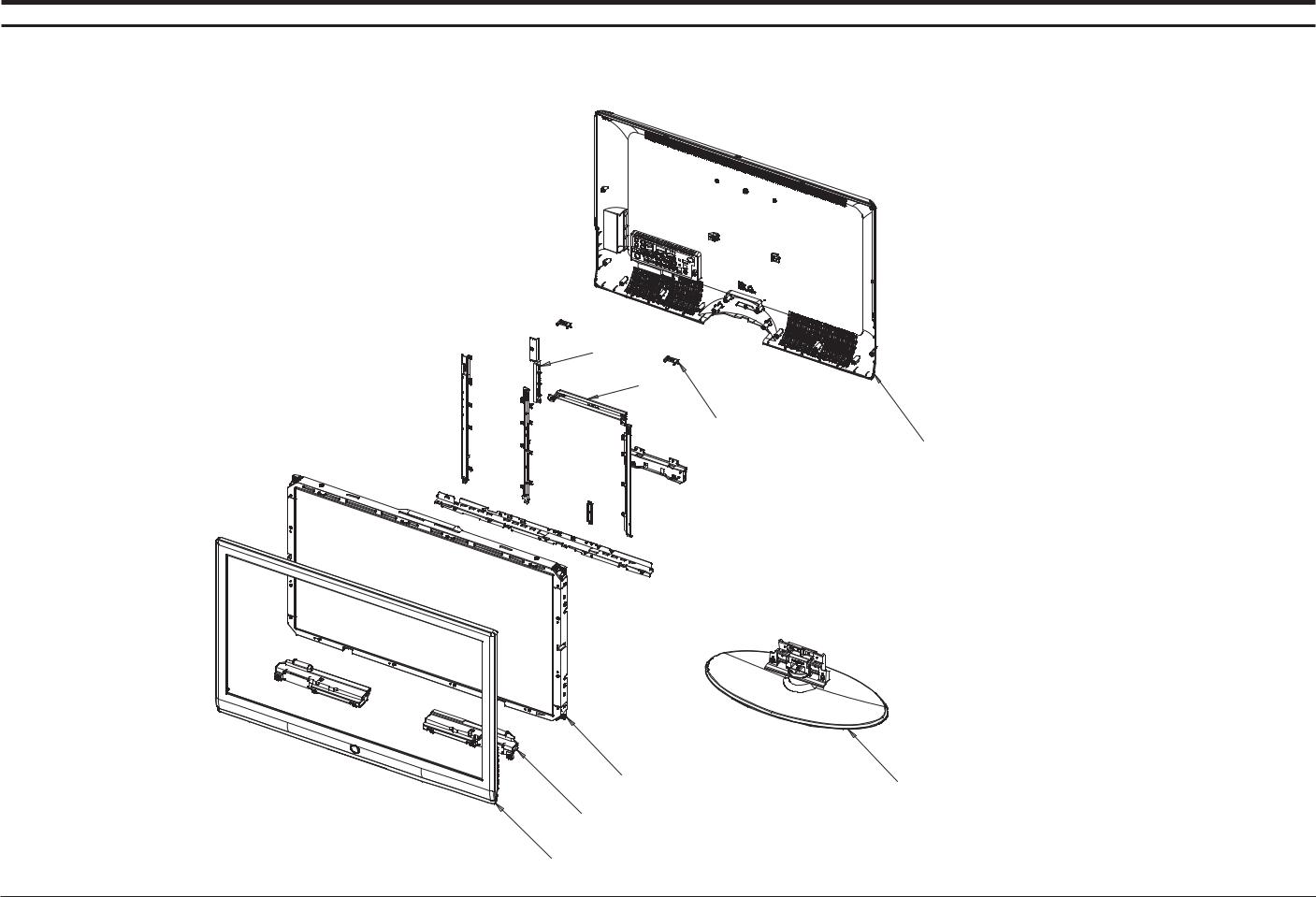
5-1 LNT4061F Exploded View
M0146
T0101
M0115
M0013
M0215
M0013
T0175
T0003
5-1

5 Exploded View & Parts List
5-2 LNT4061F Parts List
|
Location.No |
CODE-NO |
SPECIFICATION & DESCRIPTION |
Q'TY |
REMARK |
|
|
|
|
|
|
|
T0003 |
BN96-04643A |
ASSY COVER P-FRONT;40M81,UO,PC+ABS,V0,BK |
1 |
S.A |
|
|
|
|
|
|
|
T0175 |
BN96-04771A |
ASSY SPEAKER P;8ohm,4pin,Enclosure Type, |
1 |
S.A |
|
|
|
|
|
|
|
M0215 |
BN07-00409A |
LCD-PANEL;LTA400HT-L01,8bit,40inch,16.7M |
1 |
S.A |
|
|
|
|
|
|
|
T0101 |
BN61-02884A |
BRACKET-WALL;TULIP,40,SECC,T1.6,-,-,-,BR |
1 |
S.N.A |
|
M0146 |
BN61-02887A |
BRACKET-PANEL TOP;TULIP,40,SECC,T1.2,-,- |
2 |
S.N.A |
|
M0115 |
BN61-02882A |
BRACKET-STAND LINK;TULIP,40,SECC,T1.6,-, |
1 |
S.N.A |
|
|
|
|
|
|
|
T0447 |
BN96-05213A |
ASSY BRACKET P-PANEL;40M81,UO,SO,LO |
1 |
S.N.A |
|
|
|
|
|
|
|
M0013 |
BN96-04640A |
ASSY STAND P-BASE;37,40M81,-,ABS+PMMA,HB |
1 |
S.A |
|
|
|
|
|
|
|
M0013 |
BN96-04644A |
ASSY COVER P-REAR;40M81,UO,PC+ABS,V0,BK2 |
1 |
S.A |
|
|
|
|
|
|
5-2
5 Exploded View & Parts List
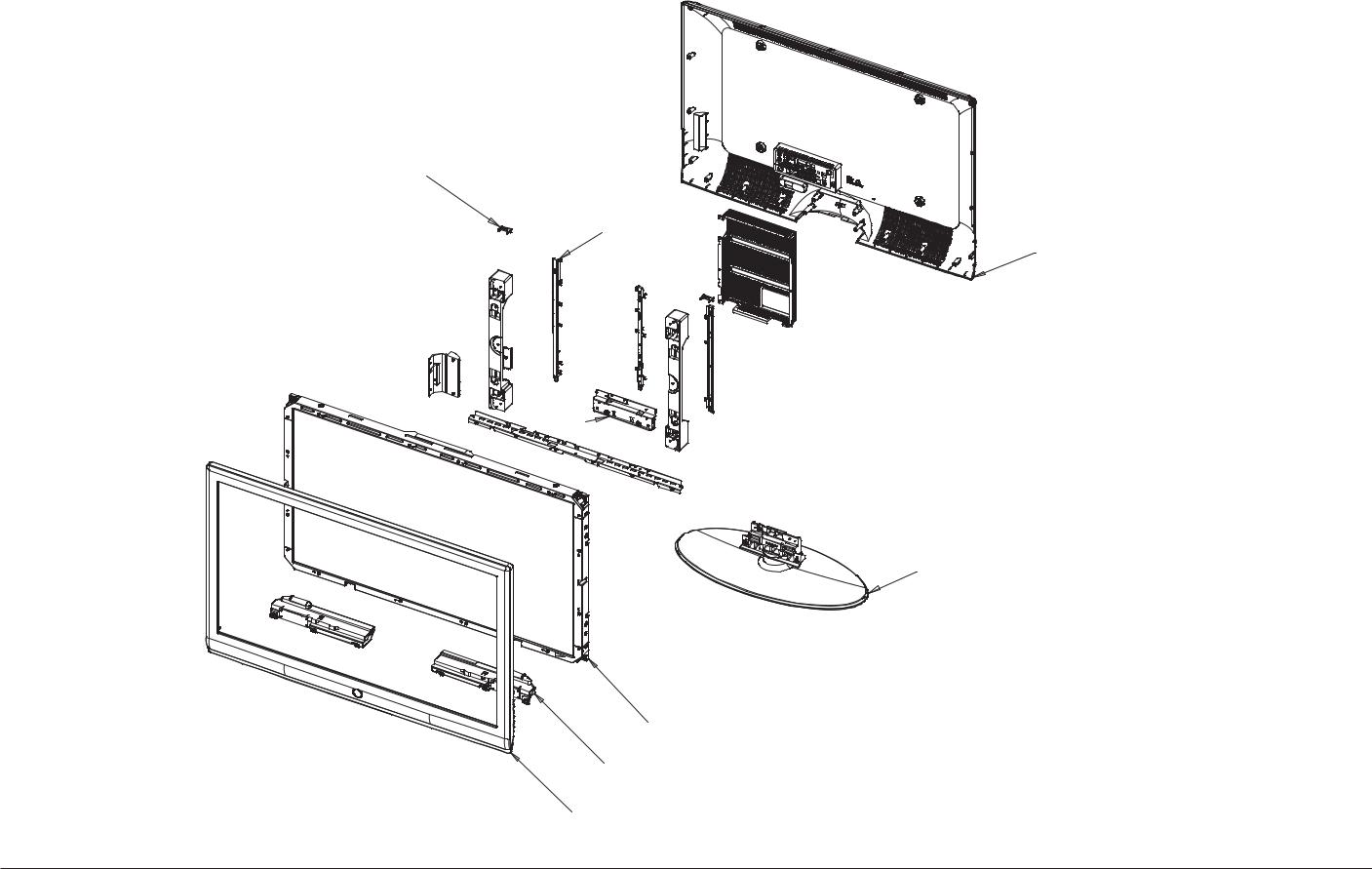
5-3 LNT4661F Exploded View
M0146
T0101
M0013
M0115
M0013
M0215
T0175
T0003
5-3
 Loading...