


 Loading...
User Manual
DBJ (DB43J DB49J)
QBH (QB65H QB75H)
QHH (QH55H QH65H)
QMH (QM49H QM55H QM65H)
The colourandthe appearance maydifferdepending onthe product, andthe specifications are subject to change without prior notice to improve the performance.
Recommended hours of use per day for the DBJ, QBH, QHH models is less than 16 hours.
Ifthe product is usedforlongerthan16 hours a day,thewarrantymaybevoid.

Table of contents
Before Using the Product
Copyright |
6 |
|
|
Safety Precautions |
7 |
Cleaning |
7 |
Storage |
8 |
Electricity and Safety |
8 |
Installation |
9 |
Operation |
11 |
Preparations
Checking the Components |
14 |
Components |
14 |
|
|
Parts |
15 |
Control Panel |
15 |
Reverse Side |
19 |
Anti-theft Lock |
22 |
Remote Control |
23 |
|
|
Before Installing the Product (Installation |
|
Guide) |
25 |
Tilting Angle and Rotation |
25 |
Ventilation |
25 |
|
|
Installing the Wall Mount |
27 |
Preparing before installingWall-Mount |
28 |
InstallingtheWall Mount |
28 |
Wall Mount Kit Specifications (VESA) |
29 |
|
|
Remote Control (RS232C) |
30 |
Cable Connection |
30 |
Connection |
33 |
Control Codes |
34 |
Connecting and Using
a Source Device
Before Connecting |
42 |
Pre-connection Checkpoints |
42 |
|
|
Connecting to a PC |
42 |
Connection Using an HDMI Cable |
42 |
Connection Using an DPCable |
43 |
Connection using a DVI cable (Digitaltype) |
43 |
Connection Using an HDMI-DVI Cable |
44 |
|
|
Connecting an External Monitor |
45 |
|
|
Connecting to a Video Device |
46 |
Connection Using an HDMI-DVI Cable |
46 |
Connection Using an HDMI Cable |
47 |
|
|
Connecting to an Audio System |
47 |
|
|
Power cord connection guide |
48 |
Attaching the Network box (Sold separately) 49
Connecting the Network box (Sold |
|
separately) |
50 |
MagicInfo |
50 |
|
|
Changing the Input source |
52 |
Source |
52 |
Web Browser |
53 |
Remote Workspace |
54 |
Using MDC
MDC Programme Installation/Uninstallation 55
Installation |
55 |
Uninstallation |
55 |
|
|
Connecting to MDC |
56 |
Using MDC via RS-232C (serial data |
|
communications standards) |
56 |
Using MDC via Ethernet |
57 |
Player feature
Player |
59 |
Viewing content |
59 |
When content is running |
60 |
Available menu |
60 |
File Formats Compatiblewith Player |
61 |
|
|
Schedule |
66 |
|
|
Clone Product |
67 |
|
|
ID Settings |
68 |
Device ID |
68 |
Device ID Auto Set |
68 |
PC Connection Cable |
68 |
|
|
Video Wall |
69 |
Video Wall |
69 |
2

Table of contents
Horizontal x Vertical |
69 |
Screen Position |
70 |
Format |
70 |
|
|
Network Status |
71 |
|
|
Picture Mode |
72 |
|
|
On/Off Timer |
73 |
On Timer |
73 |
Off Timer |
74 |
Holiday Management |
74 |
|
|
Ticker |
75 |
|
|
URL Launcher |
76 |
|
|
URL Launcher Settings |
77 |
Approving a connected device from the server 78
Setting the current time |
79 |
ScreenAdjustment
Picture Mode |
80 |
|
|
Backlight / Contrast / Brightness / Sharpness / |
|
Colour / Tint (G/R) |
81 |
|
|
Colour Temperature |
82 |
|
|
White Balance |
83 |
2 Point |
83 |
20 Point Settings |
83 |
|
|
Gamma |
84 |
HLG / ST.2084 / BT.1886 |
84 |
|
|
Calibrated value |
84 |
|
|
Advanced Settings |
85 |
Contrast Enhancer |
85 |
Black Tone |
85 |
Flesh Tone |
85 |
RGB Only Mode |
85 |
Colour Space Settings |
86 |
HDMI UHD Color |
86 |
Motion Lighting |
86 |
HDR+ Mode |
86 |
|
|
Picture Options |
87 |
Colour Tone |
87 |
Digital Clean View |
87 |
HDMI Black Level |
88 |
Film Mode |
88 |
Auto Motion Plus Settings |
89 |
Local Dimming |
89 |
Dynamic Backlight |
90 |
|
|
Picture Size Settings |
91 |
Picture Size |
91 |
Fit to screen |
91 |
Zoom and Position |
91 |
|
|
Reset Picture |
92 |
OnScreen Display
Display Orientation |
93 |
Onscreen Menu Orientation |
93 |
Source Content Orientation |
93 |
Aspect Ratio |
93 |
|
|
Screen Protection |
94 |
Auto Protection Time |
94 |
Screen Burn Protection |
94 |
|
|
Message Display |
97 |
Source Info |
97 |
No Signal Message |
97 |
MDC Message |
97 |
Download Status Message |
97 |
|
|
Language |
98 |
|
|
Reset OnScreen Display |
98 |
SoundAdjustment
Sound Mode |
99 |
|
|
Balance |
100 |
|
|
Equaliser |
100 |
|
|
HDMI Sound |
100 |
|
|
Sound on Video Call |
100 |
|
|
Sound Output |
101 |
|
|
Auto Volume |
101 |
3

Table of contents
Reset Sound |
101 |
Network
Network Status |
102 |
|
|
Open Network Settings |
102 |
Network Type |
102 |
Network Settings (Wired) |
103 |
Network Settings (Wireless) |
105 |
Use WPS |
107 |
|
|
Server Network Settings |
108 |
Connect to server |
108 |
MagicInfo Mode |
108 |
Server Access |
108 |
FTP Mode |
108 |
Proxy server |
108 |
|
|
Device Name |
108 |
System
Accessibility |
109 |
High Contrast |
109 |
Enlarge |
109 |
|
|
Start Setup |
110 |
|
|
Touch Control |
110 |
Touch Control |
110 |
Admin Menu Lock |
110 |
Time |
111 |
Clock Set |
111 |
DST |
111 |
Power On Delay |
111 |
|
|
Auto Source Switching |
112 |
Auto Source Switching |
112 |
Primary Source Recovery |
112 |
Primary Source |
112 |
Secondary Source |
112 |
|
|
Power Control |
113 |
Auto Power On |
113 |
PC module power |
113 |
Max. Power Saving |
113 |
StandbyControl |
114 |
Network Standby |
114 |
Power Button |
114 |
|
|
Eco Solution |
115 |
Energy Saving Mode |
115 |
Eco Sensor |
115 |
Screen Lamp Schedule |
116 |
No Signal Power Off |
116 |
Auto Power Off |
116 |
|
|
Temperature Control |
117 |
|
|
External Device Manager |
118 |
Keyboard Manager |
118 |
Device Connection Manager |
118 |
|
|
Play via |
119 |
|
|
Change PIN |
119 |
Security |
120 |
Safety Lock On |
120 |
Button Lock |
120 |
USB Auto Play Lock |
120 |
Mobile Connection Lock |
121 |
Remote Management |
121 |
Network Port |
121 |
USB Port |
121 |
|
|
General |
122 |
Smart Security |
122 |
Anynet+ (HDMI-CEC) |
122 |
HDMI Hot Plug |
124 |
Custom Logo |
124 |
Game Mode |
125 |
Empty Storage |
125 |
Irregular Video Wall |
125 |
|
|
Reset System |
126 |
Support
Software Update |
127 |
Update Now |
127 |
Auto update |
127 |
|
|
Contact Samsung |
127 |
|
|
Reset All |
127 |
4

Table of contents
TroubleshootingGuide
Requirements Before Contacting Samsung |
|
Customer Service Centre |
128 |
Testing the Product |
128 |
Checking the Resolution and Frequency |
128 |
Check the followings. |
129 |
|
|
Q & A |
135 |
Specifications
General |
136 |
|
|
Preset Timing Modes |
138 |
Appendix
Responsibility for the Pay Service (Cost to |
|
Customers) |
143 |
Not a product defect |
143 |
AProduct damage caused bycustomer's |
|
fault |
143 |
Others |
143 |
|
|
Prevention of Afterimage Burn-in |
144 |
What is afterimage burn-in? |
144 |
Recommended prevention practices |
144 |
|
|
Licence |
145 |
|
|
Terminology |
146 |
5

Chapter 01
Before Using the Product
Copyright
The contents ofthis manual are subjectto changewithout noticeto improve quality.
© 2017 Samsung Electronics
Samsung Electronics owns the copyright for this manual.
Use orreproduction ofthis manual in parts orentiretywithoutthe authorization of Samsung Electronics is prohibited.
Microsoft,Windows are registeredtrademarks of Microsoft Corporation.
VESA, DPM and DDC are registered trademarks of the Video Electronics Standards Association.
Ownership of all othertrademarks is attributedtotheirdue owner.
•• An administrationfee maybe charged if either
––(a) an engineer is called out at your request and there is no defect in the product (i.e. where you have failed to read this user manual).
––(b)you bringthe unitto a repaircentre andthere is no defect inthe product
(i.e. where you have failed to read this user manual).
•• The amount of such administration chargewill be advisedtoyou before anywork orhomevisit is carried
out.
6
Safety Precautions
Warning
Aserious orfatal injurymayresult if instructions are notfollowed.
Caution
Personal injuryordamageto properties mayresult if instructions are notfollowed.
Activities marked bythis symbol are prohibited.
Instructions marked bythis symbol must befollowed.
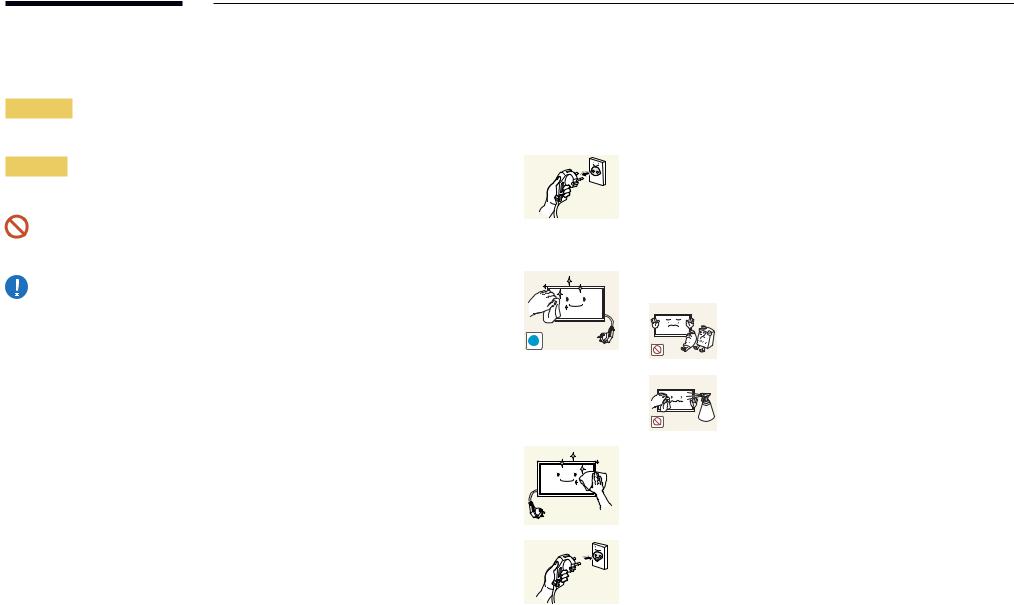
Cleaning
――Exercise care when cleaning as the panel and exterior of advanced LCDs are easily scratched. ――Take the following steps when cleaning.
――The following images are for reference only. Real-life situations may differ from what is shown in the images.
1 |
Power off the product and computer. |
2 |
Disconnect the power cord from the product. |
――Holdthe powercable bythe plug and do nottouchthe cablewith wet hands. Otherwise, an electric shock may result.
3 Wipethe productwith a clean, soft and drycloth.
•• Do not use detergents that contain alcohol, solvent
or surface-active agents.
!
•• Do not spray water or detergent directly on the product.
4 Wet a soft and drycloth inwaterandwringthoroughlyto clean
the exterior of the product.
5 |
Connect the power cord to the product when cleaning is |
|
finished. |
6 |
Power on the product and computer. |
7
Storage
Duetothe characteristics of high-glossyproducts, using a UVhumidifiernearbymaycreate white-coloured stains on the product.
――Contact Customer Service Centre if the inside of the product needs cleaning (service fee will be charged).
Electricity and Safety
――The following images are for reference only. Real-life situations may differ from what is shown in the images.
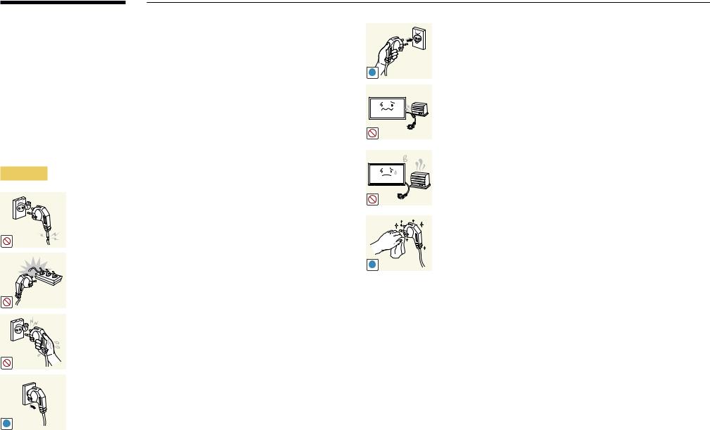
Warning
Do not use a damaged power cord or plug, or a loose power socket.
•• An electric shock or fire may result.
Do not use multiple products with a single power socket.
•• Overheated power sockets may cause a fire.
Do not touch the power plug with wet hands. Otherwise, an electric shock may result.
Insert the power plug all the way in so it is not loose.
•• An unsecure connection may cause a fire.
!
Connect the power plug to a grounded power socket (type 1 insulated devices only).
•• An electric shock orinjurymayresult.
!
Do not bend orpullthe powercordwithforce. Be careful notto leave the powercord undera heavyobject.
•• Damage to the cord may result in a fire or electric shock.
Do not place the power cord or product near heat sources.
•• A fire or electric shock may result.
Clean any dust around the pins of the power plug or the power socket with a dry cloth.
•• A fire may result.
!
8
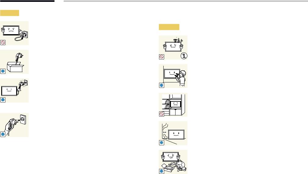
Caution
!
!
!
Do not disconnectthe powercordwhilethe product is being used.
•• The product maybecome damaged byan electric shock.
Onlyusethe powercord providedwithyourproduct bySamsung. Do not use the power cord with other products.
•• A fire or electric shock may result.
Keepthe powersocketwherethe powercord is connected unobstructed.
•• The powercord must be disconnectedto cut off powertothe product when an issue occurs.
•• Notethatthe product is not completelypowered down byusing onlythe powerbutton onthe remote.
Hold the plug when disconnecting the power cord from the power socket.
•• An electric shock or fire may result.
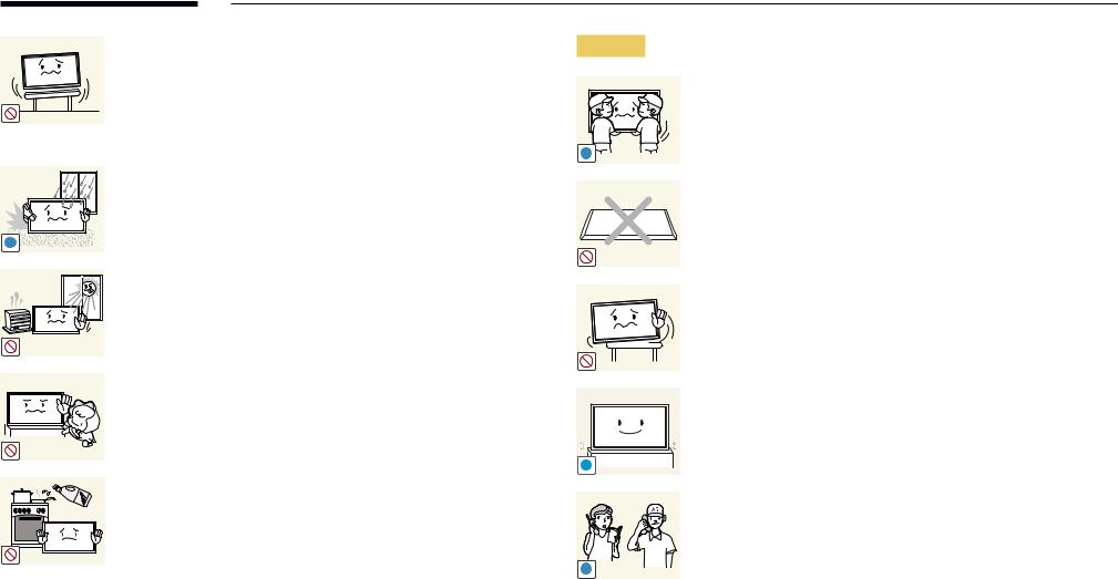
Installation
Warning
DO NOT PLACE CANDLES, INSECT REPELLANTS OR CIGARETTES ON TOP OF THE PRODUCT. DO NOT INSTALL THE PRODUCT NEAR HEAT SOURCES.
•• A fire may result.
Have a technician install the wall-mount hanger.
•• Installation byan unqualified person can result in an injury.
•• Onlyuse approved cabinets.
!
Do not install the product in poorly ventilated spaces such as a bookcase orcloset.
•• An increased internal temperature may cause a fire.
Installthe product at least10 cm awayfromthewallto allow ventilation.
•• An increased internal temperature may cause a fire.
!
Keepthe plastic packaging out ofthe reach of children.
•• Children may suffocate.
!
9
! |
Do not installthe product on an unstable orvibrating surface
(insecure shelf, sloped surface, etc.)
•• The product mayfall and become damaged and/orcause an injury.
•• Usingthe product in an areawith excessvibration maydamage the product or cause a fire.
Do not install the product in a vehicle or a place exposed to dust, moisture (water drips, etc.), oil, or smoke.
•• A fire or electric shock may result.
Do not exposethe productto direct sunlight, heat, ora hot object such as a stove.
•• The product lifespan maybe reduced orafire mayresult.
Do not install the product within the reach of young children.
•• The product mayfall and injure children.
•• Asthefront is heavy, installthe product on aflat and stable surface.
Edible oil, such as soybean oil, can damage ordeformthe product. Do not install the product in a kitchen or near a kitchen counter.
Caution
!
!
SAMSUNG 
!
Do not drop the product while moving.
•• Productfailure orpersonal injurymayresult.
Do not set down the product on its front.
•• The screen maybecome damaged.
When installingthe product on a cabinet orshelf, make surethatthe bottom edge ofthefront ofthe product is not protruding.
•• The product mayfall and become damaged and/orcause an injury.
•• Installthe product onlyon cabinets orshelves ofthe right size.
Set down the product gently.
•• Productfailure orpersonal injurymayresult.
Installing the product in an unusual place (a place exposed to a lot of fine dust, chemical substances, extremetemperatures ora significant presence of moisture, or a place where the product will operate continuously for an extended period of time) may seriously affect its performance.
•• Be sure to consult Samsung Customer Service Centre if you want to install the product at such a place.
10
Operation
Warning
There is a highvoltage insidethe product. Neverdisassemble, repair or modify the product yourself.
•• A fire or electric shock may result.
•• Contact Samsung Customer Service Centre for repairs.
!
Before moving the product, turn off the power switch and disconnect the powercable and all otherconnected cables.
•• Damage to the cord may result in a fire or electric shock.
!
!
Ifthe product generates abnormal sounds, a burning smell orsmoke,
disconnect the power cord immediately and contact Samsung
Customer Service Centre.
•• An electric shock or fire may result.
!
Do not let children hangfromthe product orclimb ontop of it.
•• Children maybecome injured orseriouslyharmed.
!
If the product is dropped or the outer case is damaged, turn off the power switch and disconnect the power cord. Then contact Samsung Customer Service Centre.
•• Continued use can result in a fire or electric shock.
Do not leave heavyobjects oritemsthat children like (toys, sweets, etc.) on top of the product.
•• The product orheavyobjects mayfall as childrentryto reachfor thetoys orsweets resulting in a serious injury.
During a lightning or thunderstorm, power off the product and removethe powercable.
•• A fire or electric shock may result.
Do not drop objects onthe product orapplyimpact.
•• A fire or electric shock may result.
Do not movethe product bypullingthe powercord oranycable.
•• Product failure, an electric shock or fire may result from a damaged cable.
If a gas leakage is found, do not touch the product or power plug. Also, ventilate the area immediately.
•• Sparks can cause an explosion or fire.
GAS
Do not lift ormovethe product bypullingthe powercord orany cable.
•• Product failure, an electric shock or fire may result from a damaged cable.
11
Do not use orkeep combustible sprayoran inflammable substance near the product.
•• An explosion or fire may result.
!
Ensurethevents are not blocked bytablecloths orcurtains.
•• An increased internal temperature may cause a fire.
|
Do not insert metallic objects (chopsticks, coins, hairpins, etc) or |
100 |
objectsthat burn easily(paper, matches, etc) intothe product (viathe |
|
vent or input/output ports, etc). |
•• Be sure to power off the product and disconnect the power cordwhenwaterorotherforeign substances have enteredthe product. Then contact Samsung Customer Service Centre.
•• Product failure, an electric shock or fire may result.
Do not place objects containing liquid (vases, pots, bottles, etc) or metallic objects ontop ofthe product.
•• Be sure to power off the product and disconnect the power cordwhenwaterorotherforeign substances have enteredthe product. Then contact Samsung Customer Service Centre.
•• Product failure, an electric shock or fire may result.
Caution
!
-_-
!
!
!
Leaving the screen fixed on a stationary image for an extended period oftime maycause afterimage burn-in ordefective pixels.
•• Activate power-saving mode or a moving-picture screen saver if youwill not be usingthe productforan extended period oftime.
Disconnect the power cord from the power socket if you do not plan on using the product for an extended period of time (vacation, etc).
•• Dust accumulation combinedwith heat can cause afire, electric shock or electric leakage.
Use the product at the recommended resolution and frequency.
•• Your eyesight may deteriorate.
Do not holdthe product upside-down ormove it byholdingthe stand.
•• The product mayfall and become damaged orcause an injury.
Looking at the screen too close for an extended period of time can deteriorate your eyesight.
Do not use humidifiers or stoves around the product.
•• A fire or electric shock may result.
12
Rest your eyes for more than 5 minutes for every 1 hour of product use.
•• Eyefatiguewill be relieved.
!
Do nottouchthe screenwhenthe product has beenturned onforan extended period oftime as itwill become hot.
Store small accessories out of the reach of children.
!
Exercise cautionwhen adjustingthe product angle orstand height.
•• Yourhand orfingermayget stuck and injured.
•• Tilting the product at an excessive angle may cause the product
tofall and an injurymayresult.
!
Do not place heavyobjects onthe product.
•• Productfailure orpersonal injurymayresult.
When using headphones orearphones, do notturnthevolumetoo high.
•• Having the sound too loud may damage your hearing.
Be carefulthat children do not placethe batteryintheirmouths when removedfromthe remote control. Placethe batteryin a location that children or infants cannot reach.
•• If children have hadthe batteryintheirmouths, consultyour doctor immediately.
When replacingthe battery, insert itwiththe right polarity(+, -).
•• Otherwise,the batterymaybecome damaged orit maycause fire, personal injuryordamage dueto leakage ofthe internal
liquid.
!
Use onlythe specified standardised batteries, and do not use a new batteryand a used batteryatthe sametime.
•• Otherwise,the batteries maybe damaged orcausefire, personal injuryordamage dueto a leakage ofthe internal liquid.
The batteries (and rechargeable batteries) are not ordinaryrefuse and must be returnedforrecycling purposes. The customeris responsibleforreturningthe used orrechargeable batteriesfor recycling.
! |
•• The customercan return used orrechargeable batteriesto a |
|
nearbypublic recycling centre orto a store sellingthe same |
|
type ofthe batteryorrechargeable battery. |
13

Chapter 02
Preparations
Checking the Components
Components
–– Contact the vendor where you purchased the product if any components are missing.
–– The appearance of the components |
|
|
|
|
|
may differ from the images shown. |
Quick Setup Guide |
Warrantycard |
Regulatory guide |
Power cord |
|
–– A stand is not provided with the |
(Not available in some locations) |
||||
|
|
|
|||
product. To install a stand, you can |
|
|
|
|
|
purchase one separately. |
|
|
|
|
|
–– TheRS232Cadaptercanbeusedto |
|
|
|
|
|
connect to another monitor using the |
|
|
|
|
|
D-SUB(9-pin)typeRS232Ccable. |
|
|
|
|
|
|
Batteries |
Remote Control |
RS232C(IN) adapter |
Cover Terminal |
|
|
(Not available in some locations) |
(Supported models: QHH) |
|||
|
|
|
Wall MountAdapter(4 EA) |
|
HOLDER-CABLE (3 EA) |
(Supported models: QHH) |
|
(Supported models: QBH, QH65H) |
|
|
|
14
Parts
Control Panel
DBJ |
|
QHH |
|
|
|
|
|
|
Speaker |
Speaker |
|
QB65H / QMH |
Remote sensor & |
|
Panel Key |
|
|
Speaker |
QB65H / QHH / QMH |
|
Spacer logo
 Remote sensor &
Panel Key
――The colourand shape of parts maydifferfromwhat is shown. Specifications are subjectto changewithout notice to improve quality.
Parts |
Description |
|
Spacer logo |
Do not pull onthe spacerlogo usingforce. The logo maytearorbreak off. |
|
――Supported models: QB65H, QMH |
||
|
||
|
Press a button onthe remote control pointing atthe bottom ofthe productfaceto |
|
|
performthefunction. The remote control sensoris located onthe bottom ofthe |
|
|
product. |
|
|
――Using other display devices in the same space as the remote control of this product |
|
|
can causethe otherdisplaydevicesto be inadvertentlycontrolled. |
|
Remote sensor |
|
|
|
To use remote/eco sensor, make sure the sliding panel key |
|
|
is protrudingfromthe bottom ofthe product. |
|
|
――Supported models: QB65H, QHH, QMH |
|
To use the panel key, make sure the sliding panel key is not |
Panel Key |
protrudingfromthe bottom ofthe product. |
|
――Supported models: QB65H, QHH, QMH |
Usethe remote controlwithin 7 mto10 mfromthe sensoronthe product at an angle of 30°fromthe left and right. ――Store used batteries out of reach of children and recycle.
――Do not use a newand used batterytogether. Replace both batteries atthe sametime. ――Remove batterieswhenthe remote control is notto be usedforan extended period oftime.
15
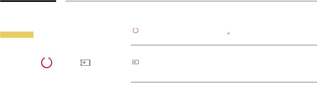
――The panel keyis located onthe bottom rightfront ofthe product.
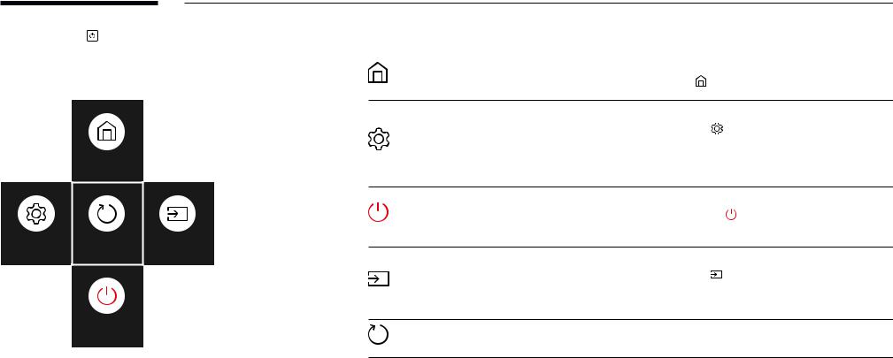
――If you press the Pbutton onthe panel keywhenthe product isturned on,the control menuwill be displayed.
Control menu
|
|
|
|
|
|
Power off |
Source |
|
Press: Move |
Press & Hold: Select |
|
|
|
|
Buttons |
|
Description |
|
||
|
|
|
|
|
|
|
|
|
|
Power off the product. |
|
|
|
|
Power off |
Withthe control menu screen displayed, brieflypressthe panel keyto move |
|
|
|
|
|||
|
|
|
|||
|
|
|
|||
|
|
|
the cursor to Power off |
, and then press and hold the panel key to turn off |
|
|
|
|
|
||
the product.
Select the connected input source.
Withthe control menu screen displayed, brieflypressthe panel keyto move
Source the cursor to Source  , and then press and hold the panel key to display the input source screen.
Withthe input source screen displayed, press and holdthe panel keyto switch to the desired input source.
――The panel keycan onlybe usedforPower off and Source.
――To exit from the control menu screen, wait for 3 seconds or more without pressing the panel key.
16

Control Panel
QB75H
Speaker
Panel Key
Spacer logo
 Remote sensor
――The colourand shape of parts maydifferfromwhat is shown. Specifications are subjectto changewithout notice to improve quality.
Parts Description
|
Power on the product. |
|
|
If you press the |
buttonwhenthe product isturned on,the control menuwill be |
|
displayed. |
|
|
――To exit the OSD menu, press and hold the panel key for at least one second. |
|
|
Movetothe upperorlowermenu. You can also adjustthevalue of an option. |
|
|
|
|
|
Move to the left or right menu. |
|
|
――You can adjustthevolume bymovingthe panel keyleft orrightwhenthe control |
|
|
menu is not displayed. |
|
|
|
|
Spacer logo |
Do not pull onthe spacerlogo usingforce. The logo maytearorbreak off. |
|
|
|
|
|
Press a button onthe remote control pointing atthe bottom ofthe productfaceto |
|
|
performthefunction. The remote control sensoris located onthe bottom ofthe |
|
Remote sensor |
product. |
|
――Using other display devices in the same space as the remote control of this product can causethe otherdisplaydevicesto be inadvertentlycontrolled.
Usethe remote controlwithin 7 mto10 mfromthe sensoronthe product at an angle of 30°fromthe left and right. ――Store used batteries out of reach of children and recycle.
――Do not use a newand used batterytogether. Replace both batteries atthe sametime. ――Remove batterieswhenthe remote control is notto be usedforan extended period oftime.
17
――If you press the button onthe panel keywhenthe product isturned |
Buttons |
|
Description |
|
|
on,the control menuwill be displayed. |
|
|
|
|
|
|
|
|
Home |
Display the Player menu. |
|
Control menu |
|
|
Move the panel key up to select Home |
in the control menu. |
|
|
|
|
|||
|
|
|
Display the OSD menu. |
|
|
|
Settings |
Move the panel key left to select Settings |
in the control menu. The OSD |
|
|
control screen will appear. Move the panel key right to select the desired menu. |
||
|
Home |
|
You can select a sub-menu item bymovingthe panel keyup, down, left, orright. |
|
|
|
To change settings, select the desired menu and press the panel key. |
||
|
|
|
Power off the product. |
|
|
|
Power off |
Move the panel key down to select Power off |
in the control menu. Next, |
|
|
|
press the panel key. |
|
Settings |
Return |
Source |
Select the connected input source. |
|
|
|
|
|
|
|
|
Source |
Move the panel key right to select Source |
inthe control menu.Whenthe |
|
|
list of input sources is displayed, move the panel key left or right to select the |
||
|
|
|
||
|
|
|
desired input source. Next, press the panel key. |
|
|
Power off |
Return |
Exit the control menu. |
|
18
Reverse Side
――The colour and shape of parts may differ from what is shown.
Specifications are subjectto changewithout noticeto improve quality.
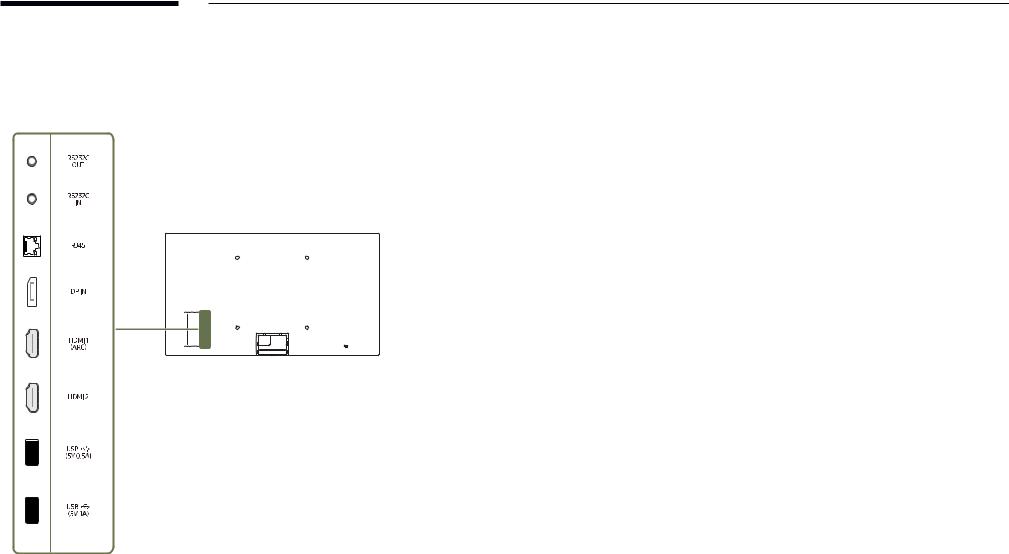
QHH
Port |
Description |
|
|
RS232C OUT |
Connects to MDC using an RS232C adapter. |
|
|
RS232C IN |
|
|
|
RJ45 |
Connectsto MDC using a LAN cable. (10/100 Mbps) |
|
――Use Cat7(*STPType) cableforthe connection. |
|
*Shielded Twist Pair. |
|
|
DP IN |
Connectsto a PC using a DPcable. |
|
|
HDMI1 (ARC) |
Connectsto a source device using a HDMI cable orHDMI-DVI cable. |
|
|
HDMI 2 |
|
|
|
USB ¨(5V 0.5A) |
Connect to a USB memory device. |
|
――The USB ports on the product accept a maximum constant current of |
|
0.5A. Ifthe maximumvalue is exceeded, USB ports maynotwork. |
|
|
USB ¨(5V1A) |
Connect to a USB memory device. |
|
――The USB ports on the product accept a maximum constant current of |
|
1.0A. Ifthe maximumvalue is exceeded, USB ports maynotwork. |
|
|
19

Reverse Side
――The colour and shape of parts may differ from what is shown.
Specifications are subjectto changewithout noticeto improve quality.
QBH QMH
Port |
Description |
|
|
USB1 ¨(1.0A) |
Connect to a USB memory device. |
|
――The USB ports on the product accept a maximum constant current of |
|
1.0A. Ifthe maximumvalue is exceeded, USB ports maynotwork. |
|
|
RJ45 |
Connectsto MDC using a LAN cable. (10/100 Mbps) |
|
――Use Cat7(*STPType) cableforthe connection. |
|
*Shielded Twist Pair. |
|
|
RS232C IN |
Connects to MDC using an RS232C adapter. |
|
|
DVI/MAGICINFO IN |
DVI: Connectsto a source device using a DVI cable orHDMI-DVI cable. |
|
MAGICINFO IN: To use MagicInfo, make sureto connectthe DP-DVI cable. |
|
|
HDMI IN1 (ARC) |
Connectsto a source device using a HDMI cable orHDMI-DVI cable. |
|
|
HDMI IN 2 |
|
|
|
HDMI IN 2 (DAISY CHAIN IN) |
|
|
|
DP IN |
Connectsto a PC using a DPcable. |
|
|
DP IN (DAISY CHAIN IN) |
|
|
|
HDMI OUT (DAISY CHAIN OUT) |
Connectsto anotherproduct using a HDMI cable. |
|
|
USB 2(0.5A) |
Connect to a USB memory device. |
|
――The USB ports on the product accept a maximum constant current of |
|
0.5A. Ifthe maximumvalue is exceeded, USB ports maynotwork. |
|
|
DVI/HDMI/AUDIO IN |
Receives soundfrom a source devicevia an audio cable. |
|
|
AUDIO OUT |
Outputs soundto an audio devicevia an audio cable. |
|
|
IR IN |
Supplies powertothe external sensorboard orreceivesthe light sensorsignal. |
|
|
RS232C OUT |
Connects to MDC using an RS232C adapter. |
|
|
20
Reverse Side
――The colour and shape of parts may differ from what is shown.
Specifications are subjectto changewithout noticeto improve quality.
DBJ
Port |
Description |
|
|
USB1 ¨(1.0A) |
Connect to a USB memory device. |
|
――The USB ports on the product accept a maximum constant current of |
|
1.0A. Ifthe maximumvalue is exceeded, USB ports maynotwork. |
|
|
HDMI IN1 (ARC) |
Connectsto a source device using a HDMI cable orHDMI-DVI cable. |
|
|
HDMI IN 2 |
|
|
|
DVI/MAGICINFO IN |
DVI: Connectsto a source device using a DVI cable orHDMI-DVI cable. |
|
MAGICINFO IN: To use MagicInfo, make sureto connectthe DP-DVI cable. |
|
|
RS232C IN |
Connects to MDC using an RS232C adapter. |
|
|
RS232C OUT |
|
|
|
RJ45 |
Connectsto MDC using a LAN cable. (10/100 Mbps) |
|
――Use Cat7(*STPType) cableforthe connection. |
|
*Shielded Twist Pair. |
|
|
DVI/HDMI/AUDIO IN |
Receives soundfrom a source devicevia an audio cable. |
|
|
AUDIO OUT |
Outputs soundto an audio devicevia an audio cable. |
|
|
21

Anti-theft Lock
――An anti-theft lock allowsyouto usethe product securelyeven in public places.
――The locking device shape and locking method depend on the manufacturer. Refer to the user guide provided with your anti-theft locking device for details.
――The following images are for reference only. Real-life situations may differ from what is shown in the images.
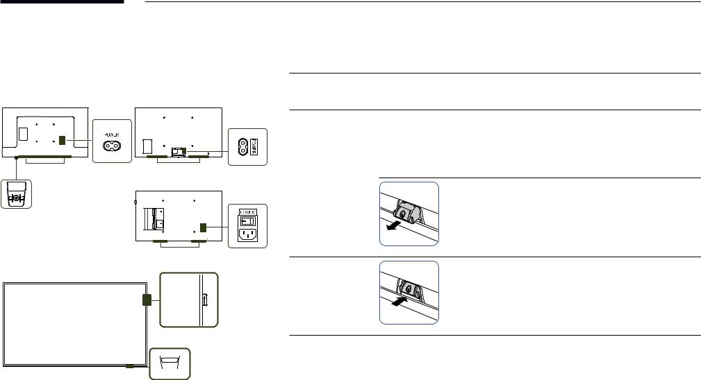
To lock an anti-theft locking device:
QBH / QHH / QMH |
DBJ |
1
2
3
4
Fixthe cable ofyouranti-theft locking deviceto a heavyobject such as a desk.
Put one end ofthe cablethroughthe loop onthe otherend.
Insertthe locking device intothe anti-theft lock slot atthe back ofthe product.
Lock the locking device.
––An anti-theft locking device can be purchased separately.
––Refer to the user guide provided with your anti-theft locking device for details.
––Anti-theft locking devices can be purchased at electronics retailers oronline.
22
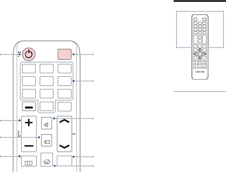
Remote Control
――Using otherdisplaydevices inthe same space asthe remote control ofthis product can causethe otherdisplaydevicesto be inadvertentlycontrolled. ――Abuttonwithout a description inthe image belowis not supported onthe product.
Power on the product.
Adjustthevolume.
Change the input source.
Display or hide the onscreen display menu, or return to the previous menu.
|
|
POWER |
|
|
|
OFF |
|
.QZ |
ABC |
DEF |
|
1 |
2 |
3 |
|
GHI |
JKL |
MNO |
|
4 |
5 |
6 |
|
PRS |
TUV |
WXY |
|
7 |
8 |
9 |
|
DEL-/-- |
SYMBOL |
|
|
0 |
CH LIST |
||
|
|||
|
|
||
|
MUTE |
|
|
VOL |
SOURCE |
CH |
|
|
|
MENU |
HOME |
MagicInfo |
|
||
|
|
Player I |
Power off the product.
Numberbuttons
Enter the password in the OSD menu.
–– Remote control buttonfunctions may differ for different products.
Mute the sound.
Unmuting the sound: Press MUTE again or press the volume control(+ VOL -) button.
DBJ / QBH / QMH: Use this hotkey to directly access MagicInfo. This hotkeyis available when a network box is connected.
Player Launch Button.
23

Quickly select frequently used functions. |
TOOLS |
INFO |
|
|
Return to the previous menu. |
RETURN |
|
|
EXIT |
|
|
|
|
|
|
PC |
DVI |
HDMI |
DP |
It sets safe lock function. |
A |
B |
C |
D |
IR control |
|
|
||
|
|
|
||
If multiple products are connected through the |
SET |
UNSET |
LOCK |
|
Video Wall feature, press the SET buttonand |
|
|
|
|
enteraproductIDusingthenumberbuttons. |
|
|
|
|
Control the product using the remote control. |
|
|
|
|
CancelavaluethathasbeensetusingtheSET |
|
|
|
|
buttonandcontrolallconnectedproductsusing |
|
|
|
|
the remote control. |
|
|
|
|

 Displayinformation aboutthe current input
source.
Move to the upper, lower, left or right menu,

 oradjust an option's setting.
Confirm a menu selection. Exit the current menu.
DBJ: Manually select a connected input source from DVI, HDMI 1 or HDMI 2.
QHH: Manually select a connected input source from HDMI 1, HDMI 2 or DisplayPort.
QBH / QMH: Manually select a connected input source from DVI, HDMI 1, HDMI 2 or
DisplayPort.
To place batteries in the remote control
––Remote control buttonfunctions may differ for different products.
––Removebatterieswhentheremote controlisnottobeusedforan extended period of time.
24
Before Installing the Product
(Installation Guide)
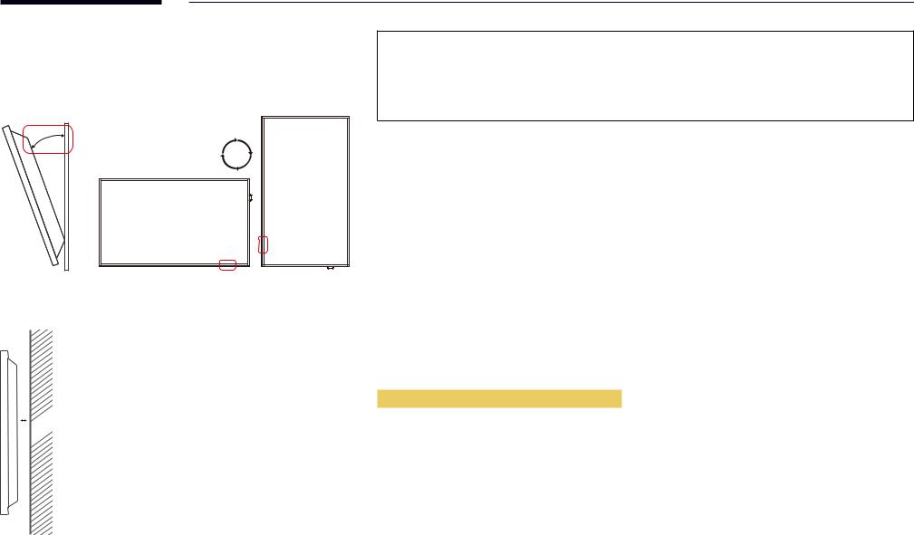
15°
A 
B
To prevent injury,this apparatus must be securelyattachedtothefloor/wall in accordancewiththe installation instructions.
•• Ensure that an authorised installation company installs the wall mount.
•• Otherwise, it mayfall and cause personal injury.
•• Make sure to install the specified wall mount.
Tilting Angle and Rotation
――Contact Samsung Customer Service Centre for further details.
•• The product can betilted at a maximum angle of15°from a perpendicularwall surface.
•• To use the product vertically (portrait), turn it clockwise so that the LED is pointing down.
Ventilation
――Contact Samsung Customer Service Centre for further details.
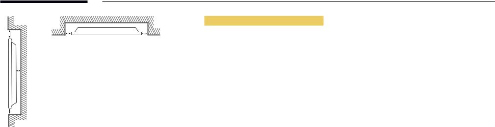
Installation on a Perpendicular Wall
A Minimum 40 mm
B Ambienttemperature: Under35°C
――When installingthe product on a perpendicularwall, allowat least 40 mm of space betweenthe product and
wall surfaceforventilation and ensurethatthe ambientAtemperature is kept below35°C.
25
|
|
|
Installation on an Indented Wall |
B |
D |
D |
A Minimum 40 mm |
|
|
||
|
|
|
B Minimum 70 mm |
|
|
|
C Minimum 50 mm |
|
|
|
D Minimum 50 mm |
|
A |
|
E Ambienttemperature: Under35°C |
|
|
|
――When installingthe product on an indentedwall, allowat leastthe space specified above betweenthe product |
|
|
|
andwallforventilation and ensurethatthe ambienttemperature is kept below35°C. |
C |
|
|
|
E
26
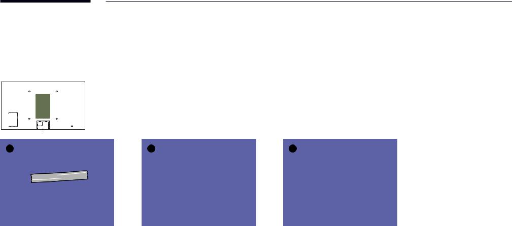
Installing the Wall Mount
――The coveris easilyremovable byhand. Removethe coverwhenyou installthewall mount. Do not removethe coverwhenyou do not installthewall mount. ――Removingthe coveris necessaryonlywhen installingtheWMN-M11E (No gapwall mount).
――Supported models: QHH
1 |
2 |
3 |
27
Preparing before installing Wall-Mount
 1
1
To install a wall-mount from another manufacturer, use the Wall Mount Adapter(1). ――Supported models: QHH
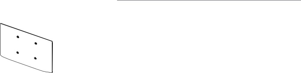
Installing the Wall Mount
The wall mount kit (sold separately) allows you to mount the product on the wall.
For detailed information on installing the wall mount, see the instructions provided with the wall mount. We recommend you contact a technician for assistance when installing the wall mount bracket.
Samsung Electronics is not responsible for any damage to the product or injury to yourself or others if you select to install the wall mount on your own.
28
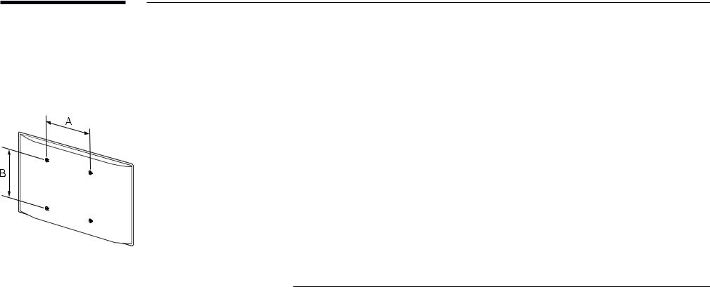
WallMountKitSpecifications(VESA)
――Install your wall mount on a solid wall perpendicular to the floor. Before attachingthewall mountto surfaces otherthan plasterboard, please contact your nearest dealer for additional information.
If you install the product on a slanted wall, it may fall and result in severe personal injury.
•• Samsungwall mount kits contain a detailed installation manual and all parts necessaryforassemblyare provided.
•• Do not use screws that are longer than the standard length or do not comply with the VESA standard screw specifications. Screws that are too long may cause damage to the inside of the product.
•• For wall mounts that do not comply with the VESA standard screw specifications, the length of the screws may differ depending on the wall mount specifications.
•• Do not fasten the screws too firmly. This may damage the product or cause the product to fall, leading to personal injury. Samsung is not liableforthese kinds of accidents.
•• Samsung is not liableforproduct damage orpersonal injurywhen a non-VESAornon-specifiedwall mount is used or the consumer fails to follow the product installation instructions.
•• Do not mount the product at more than a 15 degree tilt.
•• Always have two people mount the product on a wall.
•• Standard dimensionsforwall mount kits are shown inthetable below.
Model name |
VESA screw hole specs (A * B) Standard Screw |
Quantity |
||
|
in millimetres (inches) |
|
||
|
|
|
|
|
DBJ |
200 × 200 (7.9 × 7.9) |
M8 |
4 |
|
|
|
|||
QBH / QHH / QMH |
400 × 400 (15.7 ×15.7) |
|||
|
|
|||
――Do not installyourWall Mount Kitwhileyourproduct isturned on. It mayresult in personal injurydueto electric shock.
――If you want to use a wall mount, make sure that it allows you to remove the product from it without using any additional tool. (Supported models: DBJ)
29
Remote Control (RS232C)
Cable Connection
RS232C Cable
Interface |
RS232C (9 pins) |
|
|
Pin |
TxD (No.2), RxD (No.3), GND (No.5) |
|
|
Bit rate |
9600 bps |
|
|
Data bits |
8 bit |
|
|
Parity |
None |
|
|
Stop bit |
1 bit |
|
|
Flow control |
None |
|
|
Maximum length |
15 m (only shielded type) |
|
|
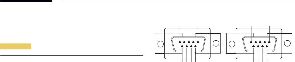
•• Pin assignment
1 |
2 |
3 |
4 |
5 |
5 |
4 |
3 |
2 |
1 |
|||||||||||
|
|
|
|
|
|
|
|
|
|
|
|
|
|
|
|
|
|
|
|
|
|
|
|
|
|
|
|
|
|
|
|
|
|
|
|
|
|
|
|
|
|
|
|
|
|
|
|
|
|
|
|
|
|
|
|
|
|
|
|
|
|
|
|
|
|
|
|
|
|
|
|
|
|
|
|
|
|
|
|
|
|
|
|
|
|
|
|
|
|
|
|
|
|
|
|
|
|
|
|
|
|
|
|
|
|
|
|
|
|
|
|
|
|
|
|
|
|
|
|
|
|
|
|
|
|
6 |
7 |
8 |
9 |
9 |
8 |
7 |
6 |
<Male type> |
<Female type> |
||||||
Pin |
Signal |
|
|
1 |
Detect data carrier |
|
|
2 |
Received data |
|
|
3 |
Transmitted data |
|
|
4 |
Prepare data terminal |
|
|
5 |
Signal ground |
|
|
6 |
Prepare data set |
|
|
7 |
Send request |
|
|
8 |
Clear to send |
|
|
9 |
Ring indicator |
|
|
30
Loading...