

Page 1

TALEA - ODEA
SERVICE
MANUAL
Revision 04 December 2012
All parts of this document are the property of Saeco International Group. All rights reserved. The manufacturer shall not accept responsibility for possible errors or omissions in this document. Any reproduction or use by
third parties is prohibited without the prior written approval of the manufacturer or through an agreement clause.
Page 2

Saeco International Group Talea / Odea - Line
Page
1. Introduction
1.1 Documents required 1
1.2 Tools and resources 1
1.3 Materials 1
1.4 Safety precautions 1
1.5 Service Policy 2
1.6.1 External appliance components 3
1.6.2 Internal appliance components 4
2. Technical specifi cations 1
2.1 Technical specifi cations
2.2 Specifi cation for the measurement of the
coffee products temperature. 2
3. Operating
3.1 User interfaces 1
3.1.1 Odea Go 2
3.1.2 Odea Giro, Talea Giro 3
3.1.3 Talea Giro Plus 3
3.1.4 Talea Ring, Ring Plus 4
3.1.5 Talea Touch 8
3.2 Use, cleaning, maintenance 12
3.3 Messages - Troubleshooting 13
4. Functional principles
4.1.1 Odea Go water system 1
4.1.2 Talea, Odea Giro water system 2
4.2 Solenoid valve, multi-way valve 3
4.3 Hot water / steam faucet 4
4.4 Coffee cycle 5
4.5 Brewing unit’s gear mechanism 6
4.6 Temperature sensor (control) 6
4.7 SBS 7
4.8 Coffee grinder 8
4.9 Dosing quantity control, coffee grinder blockage when
machine is low on beans 8
4.10 Autodose (automatic dosing quantity control) 9
Table of contents
Page 3

Saeco International Group Talea / Odea - Line
Table of contents
Page
4. Functional principles
4.11 Water level detection of fresh water tank 10
4.12 Limescale fi lter 10
4.13 Water level detection of residual water tray 11
4.14 “Empty dreg drawer” message 11
4.15 Descaling request 12
4.16 Electronical confi guration (DIP-switch setting) 12
4.17 Cup lift 13
4.18 Milk Island 13
5. Service modality
5.1.1 Test mode - Talea Giro and Odea 1
5.1.2 Special function mode - Talea Giro and Odea 2
5.2.1 Test mode - Talea Ring and Ring Plus 3
5.2.2 Diagnosis menu - Talea Ring and Ring Plus 6
5.3.1 Test mode - Talea Touch 9
5.3.2 Diagnosis menu - Talea Touch 13
5.4 Error messages 17
6. Standard controls
6.1 Repair plan 1
6.2 Service plan 1
6.3 Final control 2
7. Disassembly
7.1 SBS / dispenser 1
7.2 Housing 1
7.3 Electronics 3
7.4 Boiler pin 3
7.5 Gear motor device 4
7.6 Boiler 5
Page 4

Saeco International Group Talea / Odea - Line
Table of contents
Page
7. Disassembly
7.7 Solenoid valve / multi-way valve 6
7.8 Pump 7
7.9 Hose connections (assembly) 7
7.10 Coffee grinder 9
7.11 Grinders 10
7.12 Adjustment of coffee grinder 11
7.13 Cup lift 12
8. Notes 1
9. Water system diagrams
Odea Go
Odea Giro Plus, Giro
Talea
10. Wiring diagrams
Odea Go
Odea Giro
Talea Giro Plus
Talea Ring
Talea Ring Plus
Talea Touch Plus
Page 5

Saeco International Group Talea / Odea - Line
CHAPTER 1
INTRODUCTION
Page 6
TALEA / ODEA - LINE 01 INTRODUCTION
Saeco International Group Page 1 / 4
1.1 Documents required
The following documents are needed for repair work:
• Instruction booklet for the related model
• Technical documentation for specifi c model (diagrams, exploded view, sympton cure and
service manual).
1.2 Tools and resources
As well as the standard equipment, the following is required:
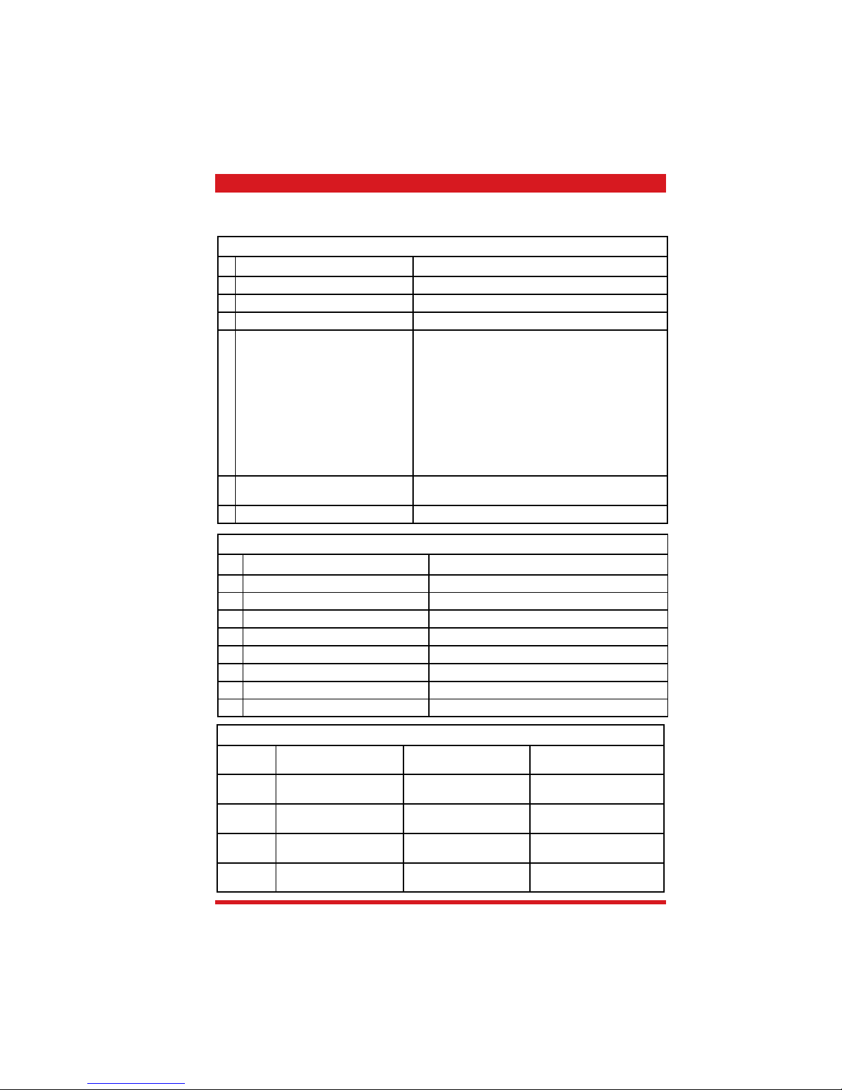
Pieces Description Comment
1 Special screwdriver Torx T 10
1 Pliers for Oetiker clamps
1 Tester CC - A - VDC
1 Digital temperature meter Temperature range > 150°C
1 SSC (Saeco Service Center) Interface for programming
1.3 Materials
Description Comment
Thermal conductance paste Temperature resistance > 200°C
Descaler Saeco descaler
Fat solvent Personal choice
Silicone grease Food-safe
1.4 Safety precautions
We recommend you consult this Service Manual of the machine before performing any maintenance work.
Observe all applicable standards relating to the repair of electrical appliances.
Always disconnect the power plug from the mains before beginning repair work.
Simply turning off the main machine power switch is not an adequate safety precaution.
This domestic appliance is rated as insulation class I.
On completion of the repair work, insulation and dielectric rigidity tests must be performed.
Page 7
Page 2 / 4 Saeco International Group
01 INTRODUCTION TALEA / ODEA - LINE
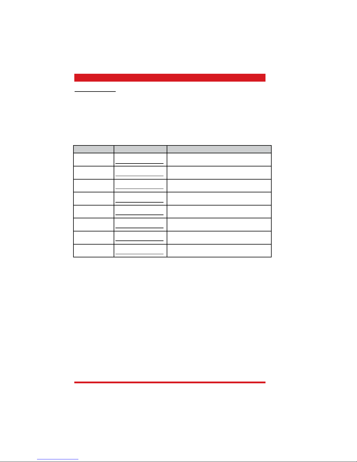
Components Assembly use Single components available
COFFEE
GRINDER
Only for OOW repairs
YES, to consult the specifi c exploded-view of the
machine or of the Coffee Grinder on website
BREWING UNIT Only for OOW repairs
YES, to consult the specifi c exploded-view of the
machine or of the Brewing unit on website
BOILER Only for OOW repairs
YES, to consult the specifi c exploded-view of the
machine on website
GEAR
MOTOR
Only for OOW repairs
YES, to consult the specifi c exploded-view of the
machine on website
FILTER
HOLDER
Only for OOW repairs
YES, to consult the specifi c exploded-view of the
machine on website
MILK
CARAFE
Only for OOW repairs
YES, to consult the specifi c exploded-view of the
machine on website
THERMAL
CARAFE
Only for OOW repairs
YES, to consult the specifi c exploded-view of the
Thermal Carafe on website
MILK ISLAND Only for OOW repairs
YES, to consult the specifi c exploded-view of the
Milk Island on website
List of principal assembly present in all our coffee machines
1.5 Service POLICY grid as used for coffee machine
For IN WARRANTY repairs is mandatory to use the single components (not the assembly) avail-
able in the exploded views of the coffee machines or of the specifi c components. If you fi nd the
information “SEE THE EXPLODED VIEW E........” in the assembly description fi eld, it means that
the single components of the assembly are available in the other pages of the exploded view. It’s
possible to use the assembly only if there is a specifi c Symptom Cure that include this possibility or
when the single components are not available for the order.
Page 8
TALEA / ODEA - LINE 01 INTRODUCTION
Saeco International Group Page 3 / 4
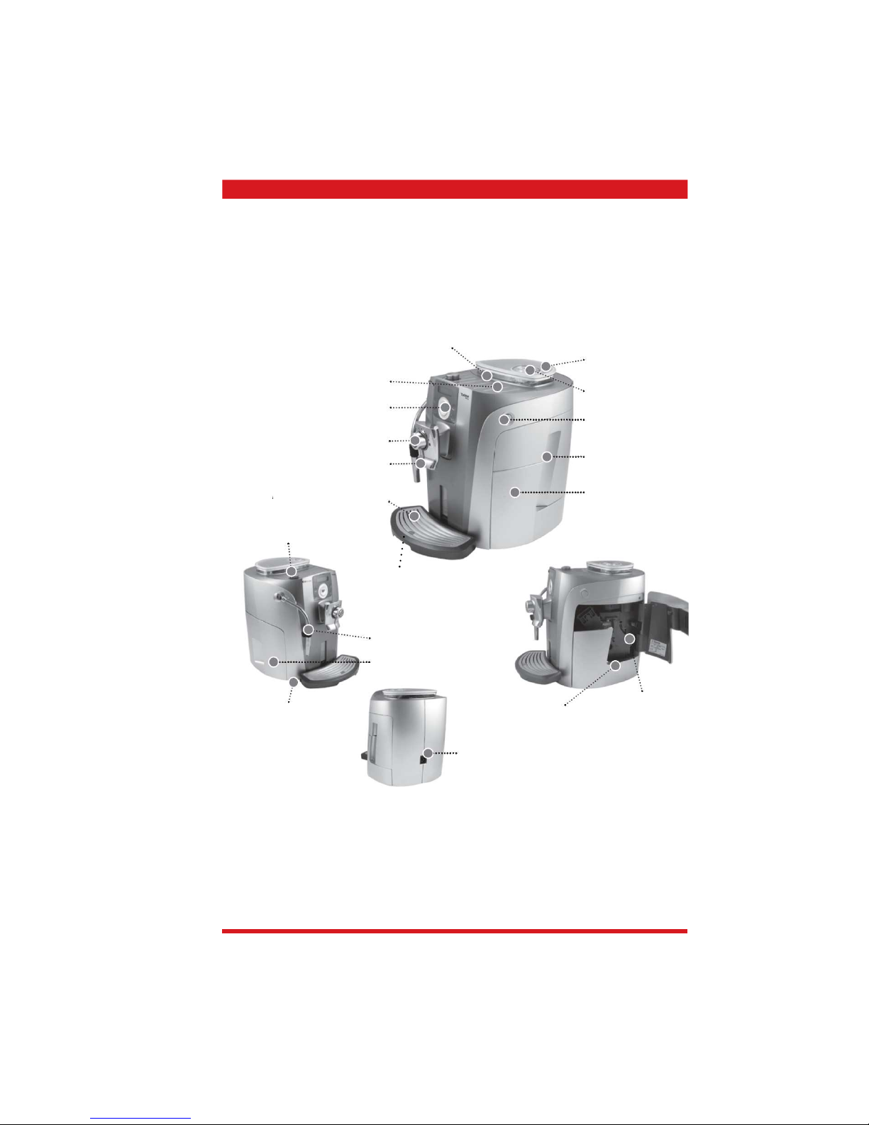
Button for lifting/lowering the drip
tray (motor controlled function,
with Touch/Ring Plus only)
1.6.1. External appliance components
Coffee bean hopper
Coffee bean hopper
lid
Funnel for ground
coffee
Service door
Dreg drawer
Brewing unit
Residual water
Socket for power
cord
Milk Island connection
port
Water tank
Hot water / steam
wand
Cup warming surface
Control panel
Dispensing head
Drip tray + grill
Hot water / steam
knob
Main switch
Saeco Brewing System SBS
Page 9

Page 4 / 4 Saeco International Group
01 INTRODUCTION TALEA / ODEA - LINE
Pump
Unblocking
fi lter
Flowmetre
Boiler
Coffee grinder
Power board
Control
board
Electrical cup lift’s motor
*Touch/Ring Plus only
Multi-way valve (not odea Go)
1.6.2. Internal appliance components
Page 10

Saeco International Group Talea / Odea - Line
CHAPTER 2
TECHNICAL
SPECIFICATIONS
Page 11
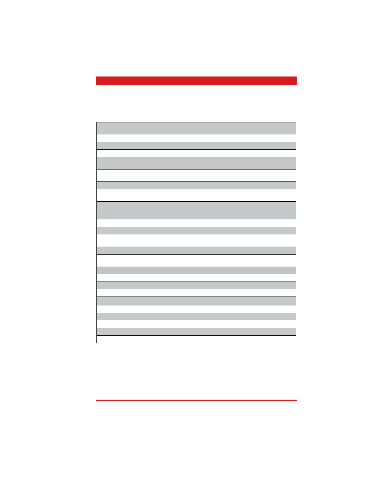
Saeco International Group Page 2 / 2
TALEA / ODEA - LINE 02 TECHNICAL SPECIFICATIONS
Connection values / power
consumption:
230 V~, 50/60 Hz, 1500 W
Temperature control: Temperature sensor (NTC, 20°C approx. 61 kOhm)
Safety equipment: 2 safety thermostats, can resist 175°C
Power output of stainless boiler: 1300 W - to dispense coffee, hot water and steam
Electrical cup lift
*Talea Touch and Ring Plus only
Stepping motor 24VDC
Tank water level and
residual water tray sensor
Capacitive sensor
Gear motor: DC motor with 2 rotating directions (24VDC)
Actively heated cup warmer:
*Talea Touch and Ring Plus only
PTC control
Pump: Ulka reciprocating piston type pump with thermal safety
100°C
48 W, 230V, 50 Hz, Type EP5 approx. 13-15 bar
Safety valve: Opens at approx. 18-20 bar
Water fi lter: in tank
Coffee grinder: DC motor with
ceramic grinders
Multi-way valve: 15 W
Coffee dose control Hall sensor - pulse control. Adjustable
coffee dosage from approx. 7 - 10.5 g set via program.
Power consumption: During heating phase - approx. 5.6 A
Dimensions: W x H x D in mm: 300/375/410
Weight: approx. 10 kg
Water tank capacity: approx. 1.7 l.
Coffee container fi lling capacity approx. 250g coffee beans
Dreg drawer capacity 14
Continuous-fl ow heater capacity: approx. 10 ccm
Water circuit fi lling time: approx. 15 seconds for fi rst fi lling cycle
Heating time: approx. 45 seconds
Grinding time: approx. 8-10 seconds
2.1. Technical specifi cations
Page 12
Page 3 / 2 Saeco International Group
02 TECHNICAL SPECIFICATIONS TALEA / ODEA - LINE
2.2. Specifi cation for the measurement of the coffee products temperature.
The temperature is infl uenced by the fl ow from the dispenser and stratifi cation of temperatures in the
glass. In order to consider these phenomena and to introduce measures that allow comparisons in controlled conditions, below guidelines must be followed:
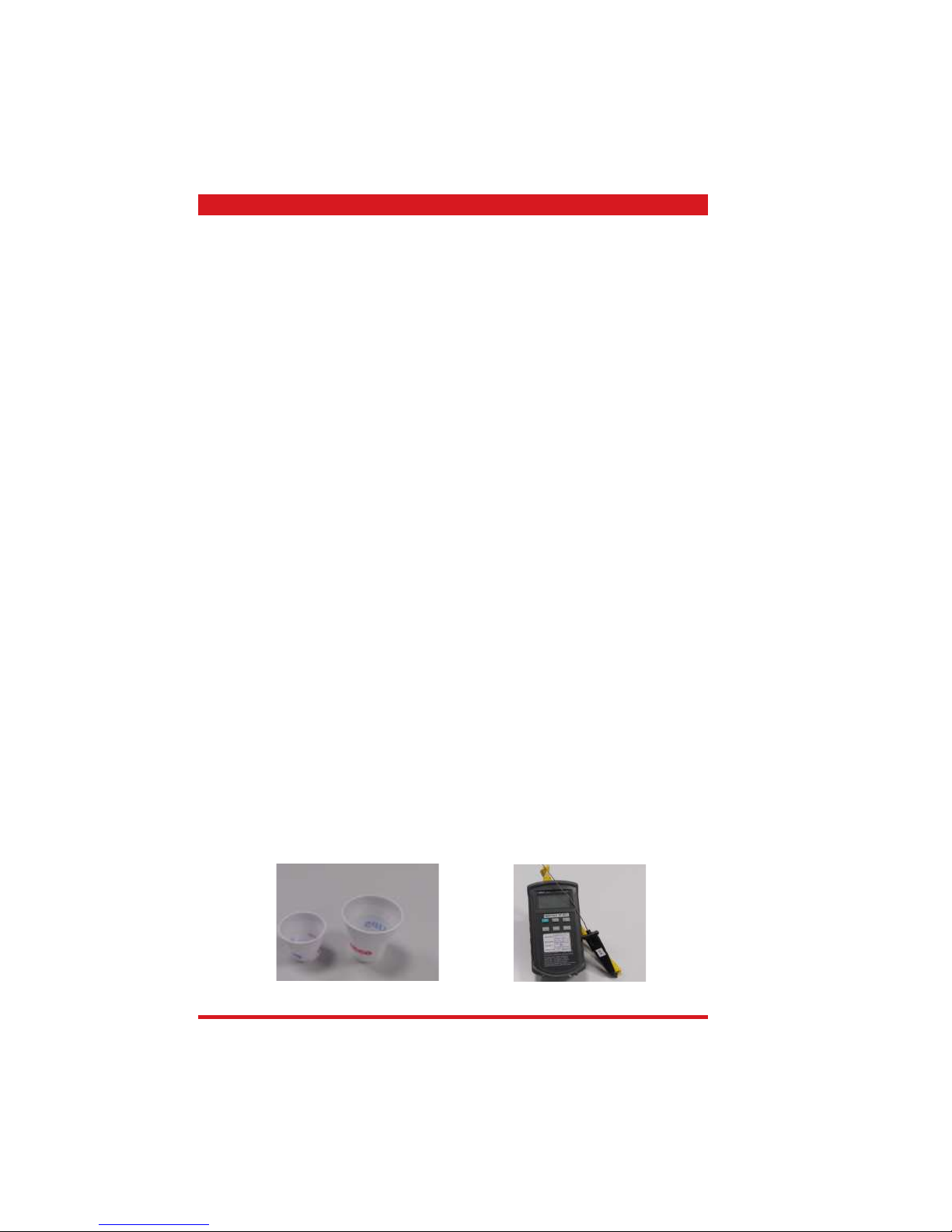
Conditions:
a) Water temperature in tank: 23°C (+/-2°C).
b) It must be used a plastic cup (see picture N°1).
c) It must be used a thermocouple thermometer (e.g. type K - see picture N°2).
d) The coffee machine is tested without any change of parameters or calibrations, which may
affect the temperature of products, so the measurement of temperature must be done with
machine in default factory setting.
Procedure:
1. The temperature must be measured in the cup, immediately after dispensing. Cup has to be
placed on a non-metal surface using a thermocouple thermometer.
2. The temperature in the cup is measured by immersing the probe of the thermometer up to
touch the bottom.The probe then must be moved in a circular motion for 5/6 rotations. At the
of the rotations, stop in the center of the cup.
3. The highest temperature measured during the rotations is the value we are searching for, and
that must be reported;
4. Test measurement: from end of dispensing to the end of rotations must be completed within 12
seconds.
Limits of acceptability
The acceptance limits are divided by features and products and are the following:
Espresso Coffee Italy Q.ty 25/40 gr.
Temperature of 1st product 69°C ≤ 85°C
Temperature of 2nd product 72°C ≤ 85°C
Coffee Q.ty 70/120 gr.
Temperature of 1st product 69°C ≤ 85°C
Temperature of 2nd product 72°C ≤ 85°C
Picture 1
Picture 2
Page 13

Saeco International Group Talea / Odea - Line
CHAPTER 3
OPERATING
Page 14
TALEA / ODEA - LINE 03 OPERATING
Saeco Internationa Group Page 1 / 13
and LEDs fl ashing alternately: turn off the appliance. Turn the appliance back on after 30 seconds and wait until the movements stop. Then turn the appliance off again. Remove the brewing unit and
clean thoroughly (see page 29). If the display reappears when you turn the machine back on, contact the
Service Centre.
Reset: Press the steam key for 10 seconds
3.1. User interfaces
3.1.1 Odea Go
“Appliance ready” LED:
• Permanently on: The appliance is ready for use.
• Flashing: The appliance has to fi nish the heating-up phase.
“Empty dreg drawer” LED:
• Permanently on: Empty the dreg drawer. The appliance must be switched on for this procedure.
“Descaling” LED:
• Flashing: Start the descaling cycle.
Control to set how much coffee is dispensed into the cup.
Coffee dispensing key:
• Flashing slowly: 1 coffee selected (key pressed once).
• Flashing rapidly: 2 coffees selected (key pressed twice).
“Hot water” key:
• On: The appliance dis-
penses steam.
• Off: The appliance dis-
penses hot water.
Alarm LED:
• Permanently on (one or more causes): No coffee left, water tank is empty, empty the residual water
tray is full (in this case the dreg drawer also has to be emptied to prevent problems).
• Flashing slowly (one or more causes): Brewing unit is missing, dreg drawer has not been inserted,
coffee container cover has not been inserted, service door is open, rotary knob for opening the hot
water / steam is not in the right position.
• Flashing rapidly: Ventilate the water system.
Page 15
Page 2 / 13 Saeco International Group
03 OPERATING TALEA / ODEA - LINE
Reset: Press the hot water key for 10 seconds
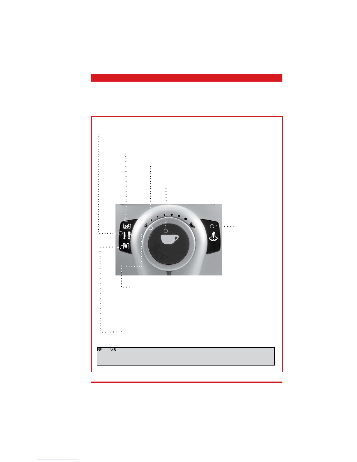
3.1.2 Odea Giro,Talea Giro
“Appliance ready” LED:
• Permanently on: The appliance is ready for use.
• Flashing: The appliance has to fi nish the heating-up phase.
“Empty dreg drawer” LED:
• Permanently on: Empty the dreg drawer. The appliance must be switched on for this procedure.
“Descaling” LED:
• Flashing: Start the descaling cycle.
Alarm LED:
• Permanently on (one or more causes): No coffee left, water tank is empty, the residual water tray is
full (in this case the dreg drawer also has to be emptied to prevent problems).
• Flashing slowly (one or more causes): Brewing unit is missing, dreg drawer has not been inserted,
coffee container cover has not been inserted, service door is open, rotary knob for opening the hot
water / steam is not in the right position.
• Flashing rapidly: Ventilate the water system.
Coffee dispensing key:
• Flashing slowly: 1 coffee selected (key pressed once).
• Flashing rapidly: 2 coffees selected (key pressed twice).
“Hot water” key:
• Off: The appliance dispenses
steam.
• On: The appliance dispenses hot
water.
Ground coffee quantity (Opti-dose)
key.
Control to set how much coffee is dispensed into the cup.
and LEDs fl ashing alternately: turn off the appliance. Turn the appliance back on after 30 seconds and wait until the movements stop. Then turn the appliance off again. Remove the brewing unit and
clean thoroughly (see page 29). If the display reappears when you turn the machine back on, contact the
Service Centre.
Page 16

TALEA / ODEA - LINE 03 OPERATING
Saeco Internationa Group Page 3 / 13
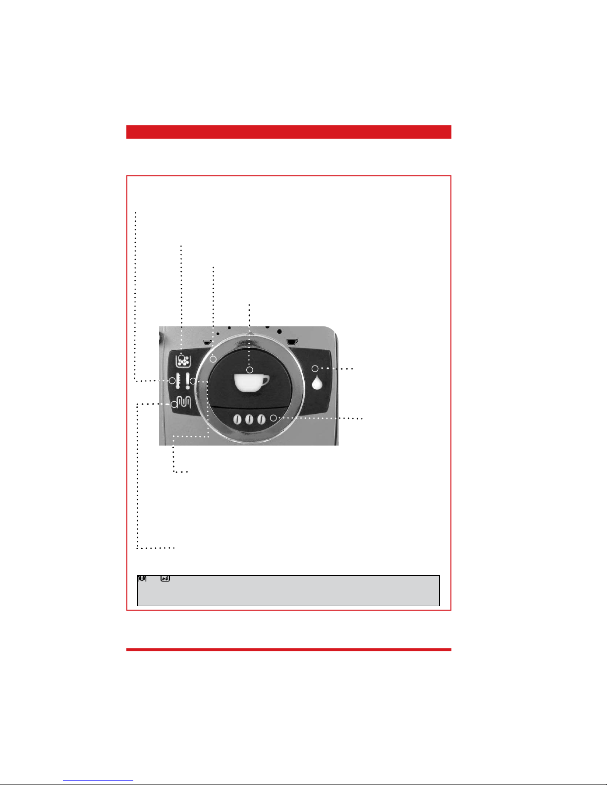
3.1.3 Talea Giro Plus
.
Reset: Press the hot water key for 10 seconds
“Appliance ready” LED:
• Permanently on: The appliance is ready for use.
• Flashing: The appliance has fi nished the heating-up phase.
“Empty dreg drawer” LED:
• Permanently on: empty the dreg drawer. The appliance must be switched on for this procedure.
“Descaling” LED:
• Flashing: Start the descaling cycle.
Alarm LED:
• Permanently on (one or more causes): No coffee left, water tank is empty, the residual water tray is full
(in this case the dreg drawer also has to be emptied to prevent problems).
• Flashing slowly (one or more causes): Brewing unit is missing, dreg drawer has not been inserted,
coffee container cover has not been inserted, service door is open, rotary knob for opening the hot water
/ steam is not in the right position.
• Flashing rapidly: Ventilate the water system.
Control to set how much coffee is dispensed into the cup.
Coffee dispensing key:
• Flashing slowly: 1 coffee selected (key pressed once).
• Flashing rapidly: 2 coffees selected (key pressed twice).
“Hot water” key:
• Off: The appliance dispenses
steam.
• On: The appliance dispenses
hot water.
“Descaling cycle” key
• On: Press for 3 seconds.
• Off: Press for 3 seconds.
Ground coffee quantity (Opti-dose) key.
and LEDs fl ashing alternately: turn off the appliance. Turn the appliance back on after 30 seconds and wait until the movements stop. Then turn the appliance off again. Remove the brewing unit and
clean thoroughly (see page 29). If the display reappears when you turn the machine back on, contact the
Service Centre.
Page 17
TALEA / ODEA - LINE 03 OPERATING
Saeco Internationa Group Page 4 / 13
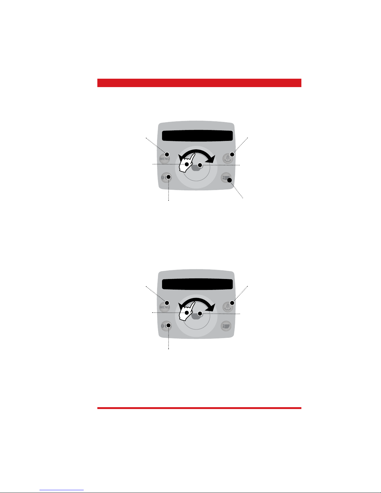
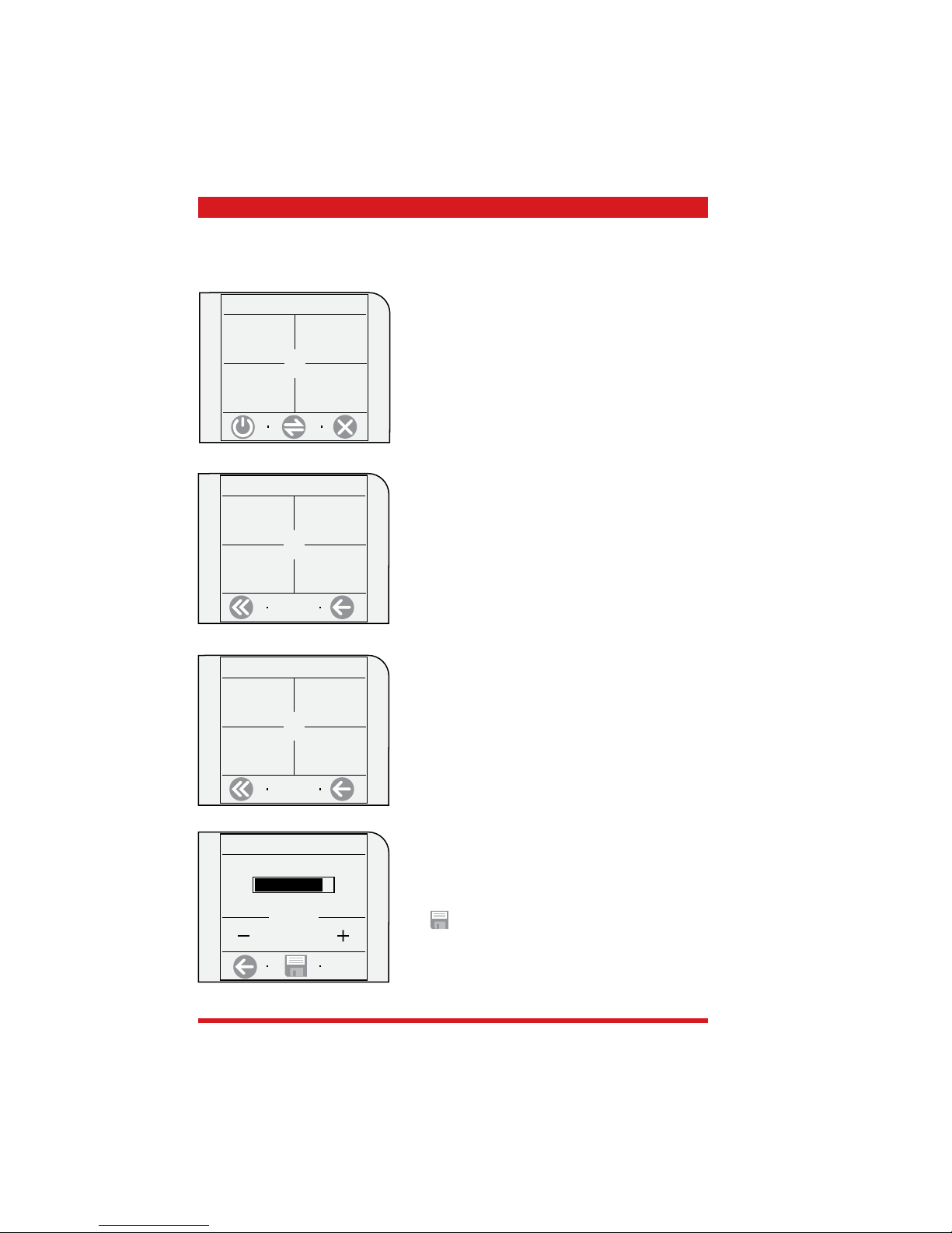
,
.
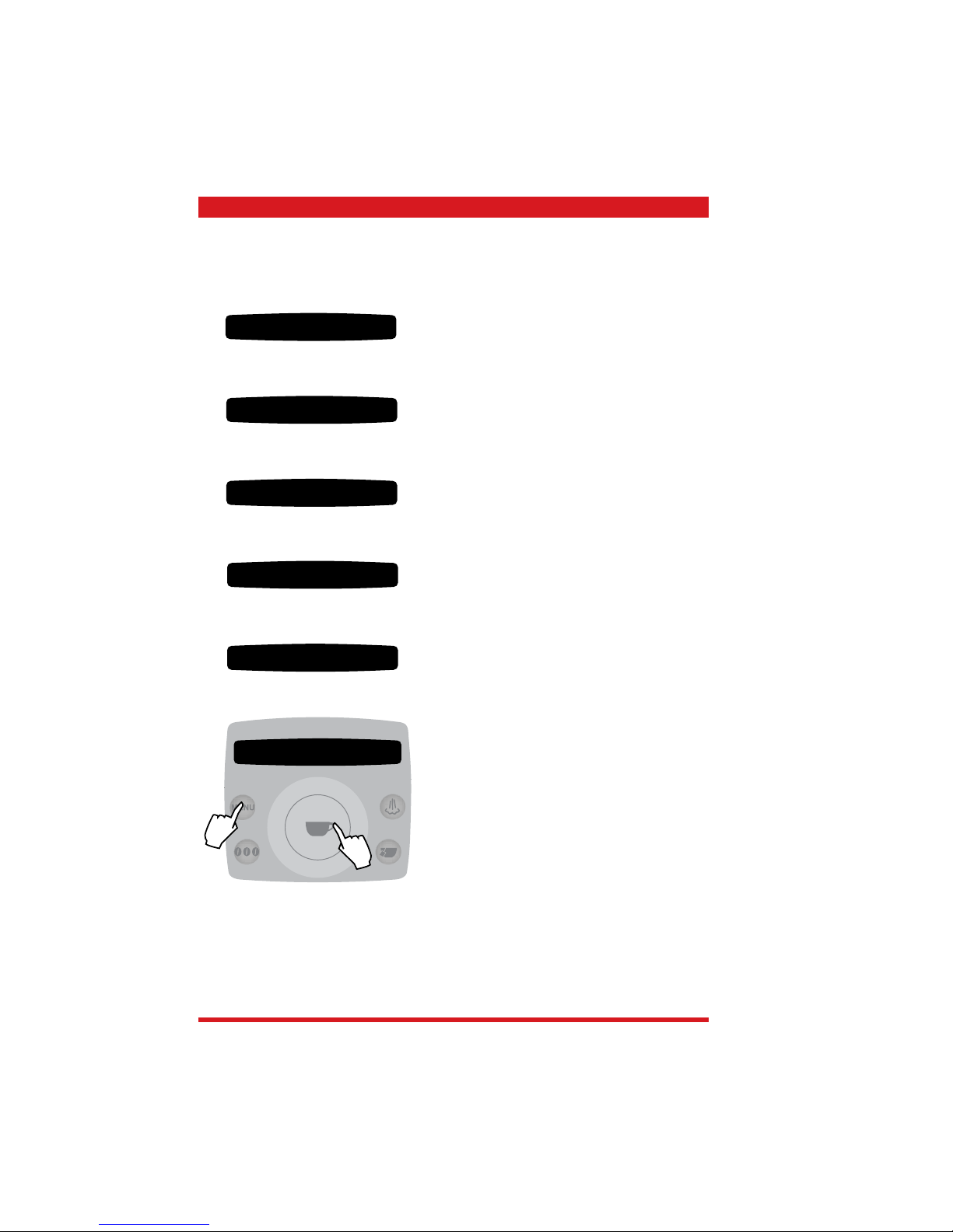
Go to
customer
menu
Activate steam function
Switch to
hot water
Coffee start key
Press once for 1 coffee
Press twice for 2 coffees
Press down longer =
quantity programming
Coffee product
selection
Selection:
Powder coffee
mild aroma
medium aroma
strong aroma
Back to the previous
level
Turn to scroll through
the menu levels and
change the parameters
Reset factory parameters
To program the following parameters for each
product (Espresso, Coffee and Large Coffee):
Aroma
Prebrewing
Press to enter the
selected menu level
or to save changed
parameters
Customer programming menu
3.1.4 Talea Ring, Ring Plus
....... aroma
coffee time
1 beverage settings
Page 18
Page 5 / 13 Saeco International Group
03 OPERATING TALEA / ODEA - LINE
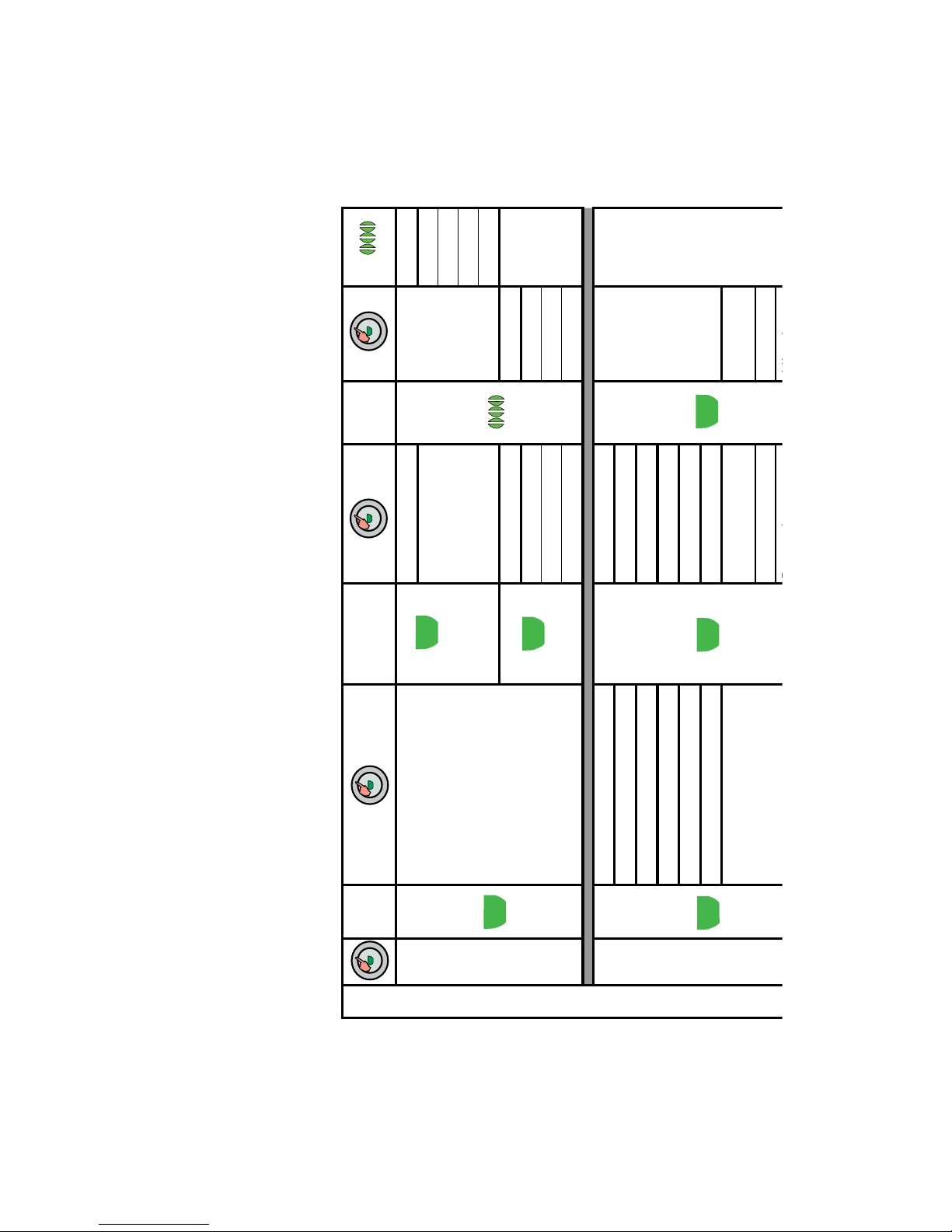
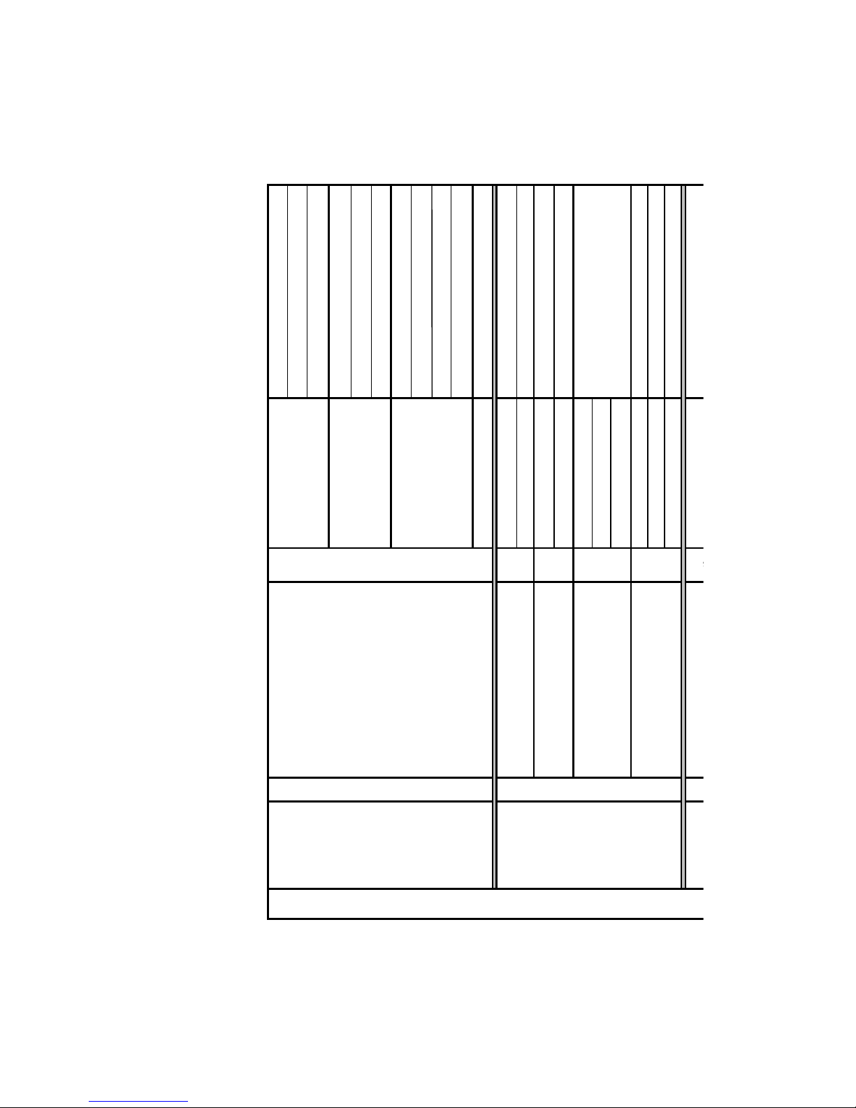
2.
Main menu levels
Dosage quantity
Temperature
Prebrewing
Language
Water hardness
Acoustic signal / alarm
Filter alarm
Rinsing
Cup warmer (Ring Plus)
Time setting (Ring Plus)
Aqua Prima
Descaling
Clean brewing unit
Switch-off time (standby)
Timer (switching time)
Restore settings (factory settings)
Cancel:
Press the menu key several times until
you see “cancel” in the display, then
confi rm with the start key
1 beverage settings
2 machine settings
3 maintenance
4 energy saving
5 special functions
Exit
Page 19
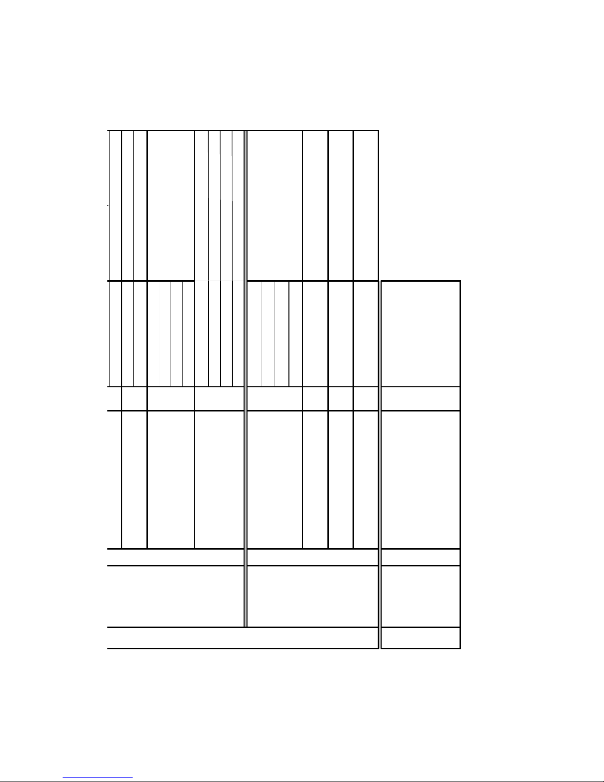
Menu key
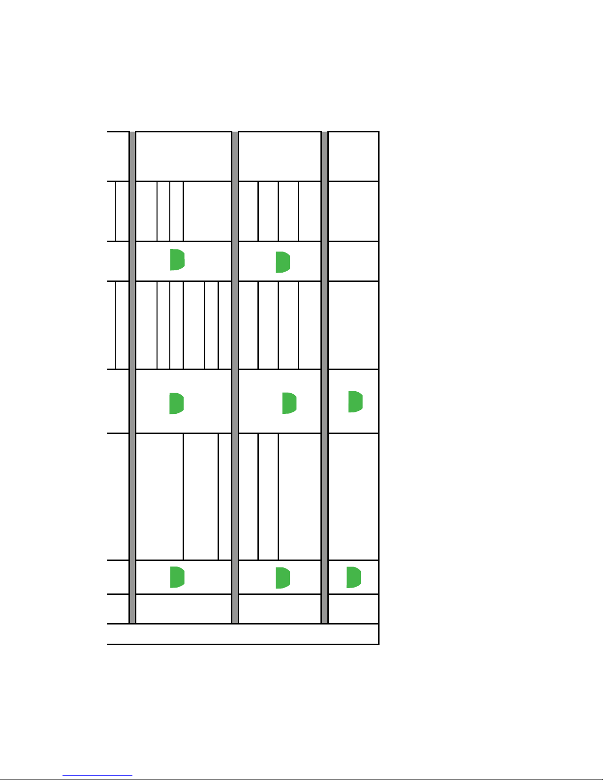
1. Beverage settings
1.1.Espresso
1.2. Coffee
1.3. Large coffee
Short press
Cup capacity Aroma
+/-
mild
medium
strong
preground
Long press
Temperature Prebrew
low normal
medium long
high off
2. Machine settings
2.1 Language 8 languages
2.2 Water hardness 1,2,3,4
2.3 Signal alarms On/Off
2.4 Water fi lter alarm On/Off
2.5 Rinsing On/Off
2.6 Cup warmer ** On/Off
2.7 Clock setting **
Time setting
Hours -
Minutes
Time format 24hr - am/pm
Date setting dd/mm/yyyy
Customer menu table
Page 20
Menu key
Date setting dd/mm/yyyy
Date format dd/mm/yy
3. Maintenance
3.1 Water fi lter
Remaining water
quantity
Filter status On/Off
Activate fi lter Activate
3.2 Descaling
Remaining water
quantity
Carry out immediately
3.3 Clean brewing unit Carry out immediately
4. Energy saving
mode
4.1 Switch-off time 15 - 180 minutes
4.2 Timer setting ** On/Off
4.3 Monday - 4.9 Sunday **
Turn on Time
Turn off Time
5. Special
case
5.1 Restore settings immediately
Restore settings,
are you sure?
** Available with Ring Plus only
Page 21
TALEA / ODEA - LINE 03 OPERATING
Saeco Internationa Group Page 8 / 13
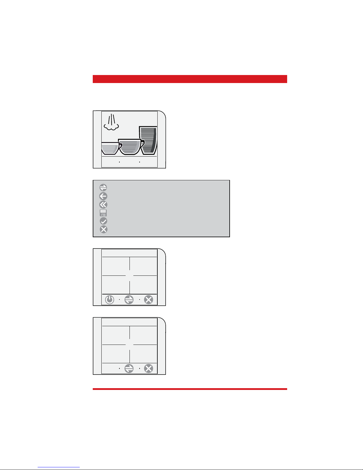
3.1.5 Talea Touch
To start:
Press the “go to menu” key
Beverage programming:
Keep the relevant beverage key pressed
show
text
8:30
24/06/06
go to
menu
beverage
settings
machine
settings
maintenance
settings
time/date
setting
beverage settings:
Espresso, Coffee and Large Coffee settings
machine settings:
Language, acoustic signals, cup warmer and water settings
time/date settings:
Time, clock timer and standby settings
maintenance settings:
Product counter, cleaning cycle, descaling cycle and
display lock
1. main menu
special
settings
special settings:
Factory settings
2. main menu
Scroll if menu point has several pages
Back to previous menu point
Back to main menu
Save
Confi rm (activate functions)
Exit menu
Page 22
Page 9 / 13 Saeco International Group
03 OPERATING TALEA / ODEA - LINE
Example, water hardness setting
Press the “water settings” key
1.2 machine settings
water settings
cup - warming
surface
alert and
acoustic
setting
language &
display
.
1.2.4 water settings
water hardness
3/4
water fi lter
Off
rinse
On
Press the “Water hardness” key
3
1.2.4.3 water hardness
Carry out the settings with the +/- keys and save with
the
save key.
In the fi rst main menu, select “machine settings”
beverage
settings
machine
settings
maintenance
settings
time/date
setting
1. main menu
Page 23
1. Main menu
Beverage
settings
1.1. Beverage setting
Espresso
Coffee
Large coffee
1.1.1. Espresso/ 1.1.2.Coffe/1.1.3.Large
Coffee
Prebrewing
normal
strong
off
Temperature
low
medium
high
Aroma
mild
normal
strong
preground
Coffee capacity
+ / -
Machine
settings
1.2. Machine settings
Language & display
1.2.1.
Language
11 languages
Contrast + / -
Acoustic signals and alarms
1.2.2.
Machine ready
On/Off
Key tone
On/Off
Heated cup holder
1.2.3.
always on
always off
off in standby
Water settings
1.2.4.
Rinse On/Off
Aqua Prima On/Off
Water hardness 1,2,3,4
Time settings
1.3.1.
Current time
+ / -
Customer menu table
Page 24
1. Main menu
Clock settings
1.3. Clock settings
Time settings
1.3.1.
+ / -
Time format Select
Date settings
1.3.2.
Current date Year / Month / Day
Date format
Select
Standby setting
1.3.3.
after 15 minutes
after 30 minutes
after 1 hour
after 3 hours
Machine on/off
1.3.4.
Interval 1
Hours / Minutes
Interval 2 Hours / Minutes
Interval 3 Hours / Minutes
Day settings Select
Maintenance
settings
1.4. Maintenance settings
Product counter
1.4.1.
Espresso
Coffee
Large coffee
Reset
Cleaning cycle
1.4.2
Yes/no
Descaling cycle
1.4.3
Yes/no
Display lock
1.4.4
Release
2. Main menu
Special
settings
2.1. Special settings
Factory settings
2.1.1.
no/yes
Page 25
TALEA / ODEA - LINE 03 OPERATING
Saeco Internationa Group Page 12 / 13
3.2 Use, cleaning and maintenance
Cleaning and service
A Empty dreg drawer When message appears
B Empty drip tray When message appears
C Clean water tank Weekly
D Clean coffee bean hopper As necessary
E Clean housing As necessary
F Clean brewing unit 2 - 3 x weekly or after 50 coffees
H Carry out a descaling cycle When message appears
J Clean drip tray Weekly
K Clean brewing unit compartment Weekly
Descaling cycles
Hardness Water hardness Interval without lim-
scale fi lter
Interval with limscale
fi lter
1 Soft water
(up to 7ºdH)
approx. every 3 months /
120 litres
approx. every 6 months /
240 litres
2 Medium hard water
(7º-14ºdH)
approx. every 2 months /
90 litres
approx. every 4 months /
180 litres
3 Hard water
(15º-21ºdH)
approx. every 6 weeks /
60 litres
approx. every 3 months /
120 litres
4 Very hard water
(over 21ºdH)
approx. every 4 weeks /
30 litres
approx. every 6 weeks /
60 litres
Using the machine
1 Insert the limescale fi lter If available
2 Fill water tank
3 Fill bean hopper
4 Turn on the appliance
5 Carry out machine settings (machines
with display only)
Determine and set water hardness, activate limescale
fi lter
IMPORTANT: if the limescale fi lter is not inserted for
longer periods, the relevant setting must be set to "OFF"
otherwise the descaling interval calculated by the appliance is too long and this results in limescale building up
in the appliance.
Two settings must be programmed on models with ring
function:
1. Machine settings: 2.4 Alarm Filter ON/OFF
2. Maintenance / Aqua Prima: 3.1.2 Additional Filter ON/
OFF
6 Specify the product
(machines with display only)
Cup capacity, dosing quantity, prebrewing
7 Press the start key Press 1x for 1 coffee, press 2x for 2 coffees
Page 26
Page 13 / 13 Saeco International Group
03 OPERATING TALEA / ODEA - LINE
DISPLAY MESSAGE SHOWN INSTRUCTIONS FOR TROUBLESHOOTING
Turn machine off and on to solve the problem Turn the appliance off and then back on after 30
seconds to resolve the fault.
Call Service Centre The problem requires the intervention of the Service
Centre
Insert drip tray Insert the drip tray
Close coffee bean hopper lid The coffee bean hopper lid must be closed to
produce beverages.
Insert ground coffee This message is shown if the user selected the use of
this type of coffee when the products were specifi cally
programmed.
Insert brewing unit Insert the brewing unit in its intended location
Insert dreg drawer Insert the dreg drawer
Empty dreg drawer Remove the dreg drawer and empty.
NOTE: the dreg drawer must only be emptied when
the appliance is switched on. The drawer must
be removed for at least 5 seconds. If the drawer
is emptied when the appliance is switched off the
message is not reset.
Close side door Close the service door.
Fill water tank Fill the water tank
Empty residual water tray Empty residual water tray
Prime circuit Start the automatic water cycle fi lling The appliance
makes 5 attempts to fi ll the cycle automatically.
If these attempts fail, the Service Centre must be
informed about these ventilation attempts.
The descaling cycle did not run correctly. Repeat the operation as described in the appropriate
chapter in the instruction booklet
Replace Aqua Prima fi lter This message is only displayed if the fi lter control is
enabled (see notes in the instruction booklet)
The fi lter should be replaced in the following cases:
1) Over 60 litres of water have been dispensed for
drinks
2) 90 days have elapsed since installation
3) 20 days have elapsed since the coffee maker was
last used.
The cleaning cycle did not run correctly Repeat the operation as described in the relevant
chapter in the instruction booklet.
Descale appliance Carry out the descaling cycle
Standby Press the “ON” key
3.3 Messages - troubleshooting
Page 27

Saeco International Group Talea / Odea - Line
CHAPTER 4
FUNCTIONAL
PRINCIPLES
Page 28
Saeco Intrnational Group Page 1 / 14
TALEA / ODEA - LINE 04 FUNCTIONAL PRINCIPLES
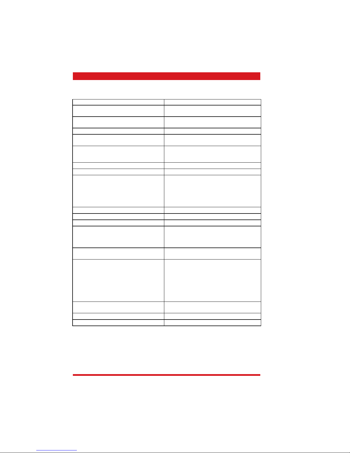
4.1.1 Odea Go water system
Caldaia 1
Rubinetto
Gruppo
Pompa EP5
Serbatoio
Turbina
Perno Caldaia
con spillo
Valvola
sicurezza
Odea Go
• Conventional water system
• Flowmetre - cup capacity / ventilation display
• Reciprocating piston type pump (13 - 15 bar)
• Overpressure valve (opening pressure 18 - 20 bar).
• Boiler (= continuous-fl ow heater) 1300 W
• Valve pin (mechanical valve opener)
• Hot water / steam valve (switch between coffee / hot water, steam output)
Pump
Flowmetre
Water tank
Boiler
Hot water /
steam valve
Brewing unit
Valve pin
Overpressure
valve
Page 29
Page 2 / 14 Saeco Internationa Group
04 FUNCTIONAL PRINCIPLES TALEA / ODEA - LINE
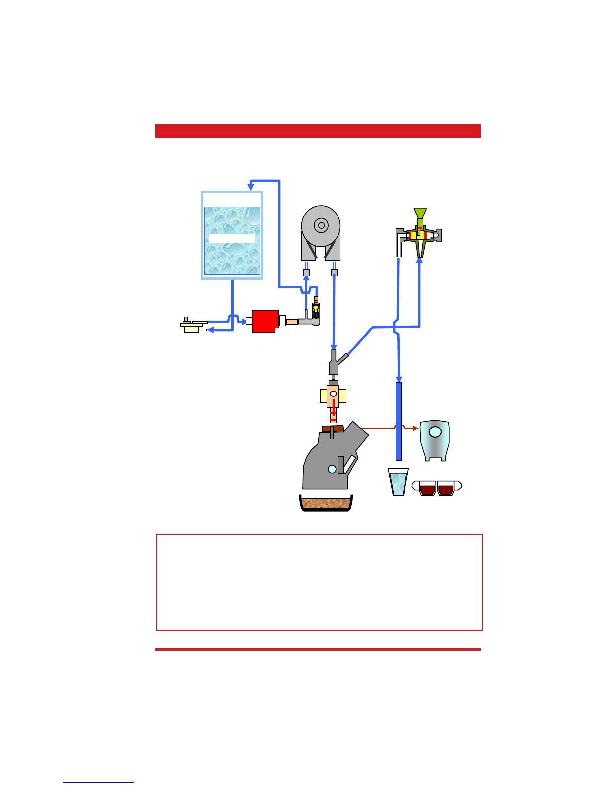
Talea, Odea Giro
• The solenoid valve has several functions and these are described in the following paragraphs. A mechanical overpressure valve is integrated in the electrical valve which opens
at approx. 18 - 20 bar.
• When dispensing coffee and the hot water / steam valve is closed, the coffee valve opens
at approx. 4 bar and the water is pressed through the brewing unit.
• The overpressure valve in the steam pipe to the Milk Island protects the system against
damage caused by pressure, the steam state overpressure is fed back to the fresh water
tank.
• The multi-way valve opens selectively depending on the operating situation in the fl ow
direction (dispensing) or against the fl ow direction (pressure release).
Caldaia 1
Perno Caldaia
senza spillo
Sistema di
sicurezza
Milk Island
solo su Talea
Elettropilota
Valvola 3
4 bar
Valvola 2
4bar
Valvola 1
scarico
Rubinetto
Pompa EP5
Serbatoio
Turbina
Gruppo
4.1.2 Talea, Odea Giro water system
Electrical valve
Overpressure
valve (steam
pipe) Milk
Island
Pump
Water tank
Boiler
Hot water / steam valve
Pin without
valve
Brewing unit
Two-way valve
Flowmetre
Milk Island
Residual water tray
Valve pressure
reduction approx.
4 bar
Coffee valve
approx. 4 bar
Talea series only
Page 30
Saeco Intrnational Group Page 3 / 14
TALEA / ODEA - LINE 04 FUNCTIONAL PRINCIPLES
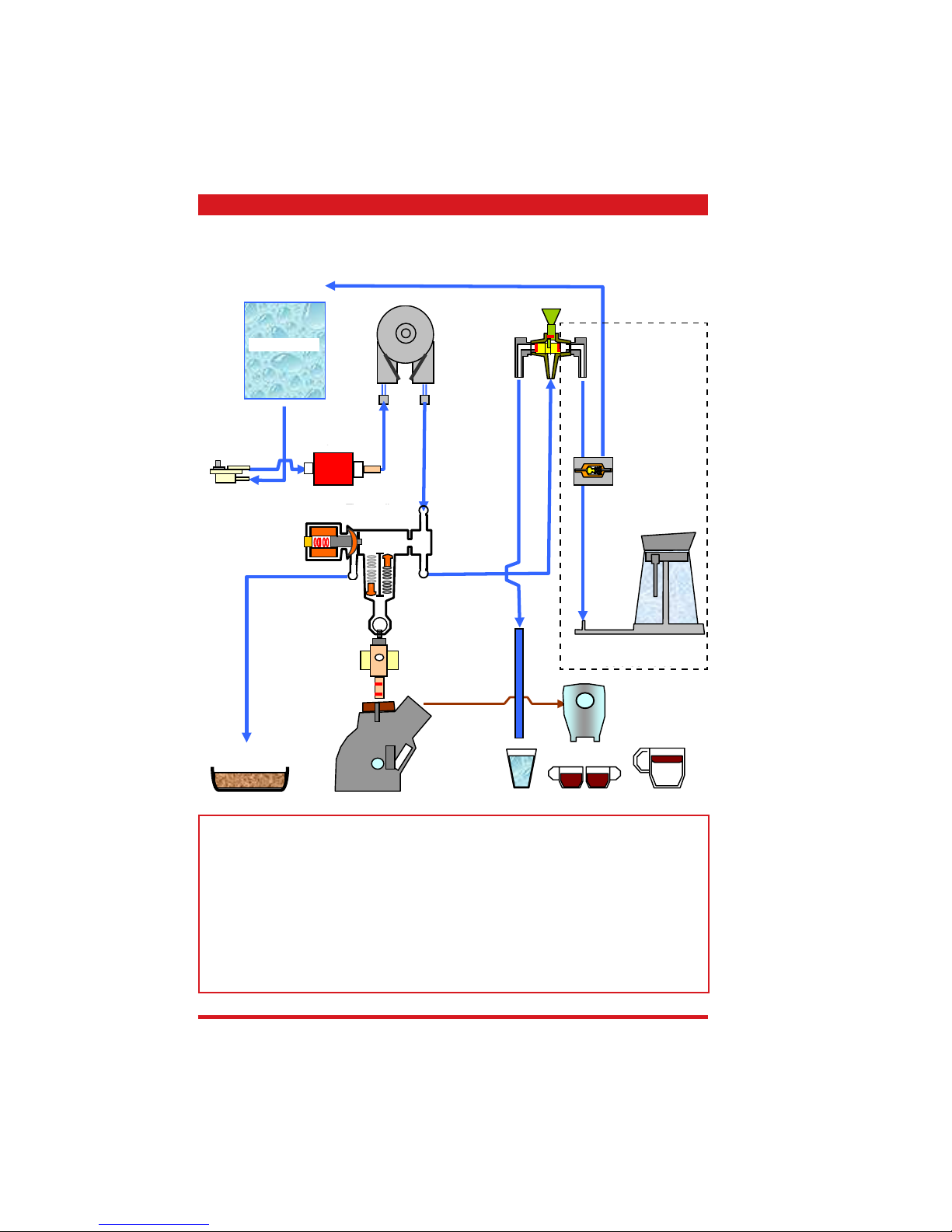
Brewing unit pressure reduction:
Before the brewing unit moves to the home
position after a brewing process, the electric
valve opens and the overpressure in the brewing chamber is released and escapes into the
residual water tray.
Wasserauslaufstutzen
Pin
3-5 bar coffee dispensing valve
Release valve
16-19 bar safety valve
4.2. Solenoid valve / multi-way valve
Wasserauslaufstutzen
Pin
3-5 bar coffee dispensing valve
Release valve
16-19 bar safety valve
Ventilation:
After the appliance is switched on, the electric
valve opens, the pump is activated and the
appliance is ventilated automatically.
Preheating the pipes:
If the coffee machine has not been used for
a while or after each heating-up phase, the
pump is activated during the grinding process.
The hot water enters via the pipes, the multiway valve, and the water channel into the
residual water tray.
When coffee is dispensed:
The same applies for when coffee is dispensed,
only the brewing unit is positioned in the
brewing position and is docked to the pin.
Wasserauslaufstutzen
Pin
3-5 bar coffee dispensing valve
Release valve
16-19 bar safety valve
from boiler
from boiler
to residual
water tray
to residual
water tray
to hot water /
steam valve
to hot water /
steam valve
from boiler
to residual
water tray
to hot water /
steam valve
18-20 bar safety valve
18-20 bar safety valve
18-20 bar safety valve
Page 31

Page 4 / 14 Saeco Internationa Group
04 FUNCTIONAL PRINCIPLES TALEA / ODEA - LINE
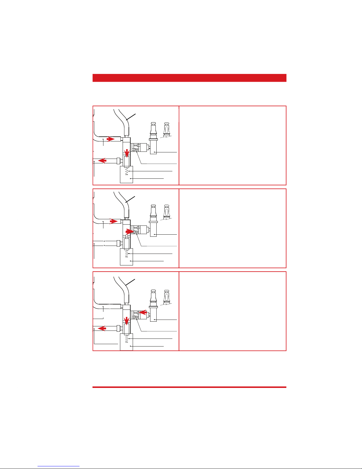
Hot water / steam faucet
The hot water / steam valve has 3 positions:
1. Middle position = closed
2. Hot water / steam
3. Milk Island (not with Odea)
The three hot water / steam valve positions
are monitored using three Hall sensors and a
magnet that is fi tted to the hot water / steam
valve axle.
Hot water /
steam
from boiler
to Milk Island
Hall sensors
Magnet
Pipe system pressure reduction:
The electrical valve opens to reduce the
pressure in the pipe system:
Each time hot water or steam is used
Each time milk is frothed with the Milk Island.
Wasserauslaufstutzen
Pin
3-5 bar coffee dispensing valve
Release valve
16-19 bar safety valve
Overpressure valve (safety valve):
As the multi-way valve already opens at 3 - 5
bar in the fl ow direction, it takes over the
overpressure function (1) when the brewing
unit is not in the brewing position. If the
brewing unit is positioned in the brewing
position in an overpressure situation and/or
the multi-way valve is blocked, the magnet
valve acts as an overpressure valve and opens
mechanically against the spring pressure at
16 - 19 bar (2).
Wasserauslaufstutzen
Pin
3-5 bar coffee dispensing valve
Release valve
16-19 bar safety valve
(1)
(2)
to hot water /
steam valve
to hot water /
steam valve
from boiler
from boiler
to residual
water tray
to residual
water tray
4.3. Hot water / steam faucet
18-20 bar safety valve
18-20 bar safety valve
Page 32

Saeco Intrnational Group Page 5 / 14
TALEA / ODEA - LINE 04 FUNCTIONAL PRINCIPLES
To turn on:
• When the main switch is activated, the gearing mechanism searches for its original position
and moves downwards into the Microswitch (MS) (with cam 1, see the following section).
The gear motor changes the direction of rotation, moves back up and stops approx. 1 - 2
mm after leaving the microswitch.
• The continuous-fl ow heater then starts to heat the water for approx. 45 seconds to reach
the operating temperature,
• 40 seconds of which is spent at full heating power and the rest is spent recycling the power.
Coffee cycle:
1. The coffee grinder starts the grinding process (pulse-controlled).
2. The gearing mechanism (brewing unit) moves to the brewing position.
3. Then the prebrewing begins (brief pumping activity, then a quick break).
4. Brewing procedure (length of the pumping activity, depending on the coffee quantity
selected).
5. The gearing mechanism moves to its original position (brew grounds are automatically
ejected).
4.4. Coffee cycle
Main switch ON START STOP
Timing
Coffee grinder
Pulse
(Dosage)
Heating
approx. 45
secs
Pump
*
Pump activity
(fl owmetre pulses)
according to cup
capacity
Gearing motor /
brewing unit
Status Warm-up phase Ready Coffee cycle
Note: * With prebrewing only
Status MS1
Status MS2
OFF ON
Gearing mechanism with 2 microswitches (MS)
Status MS
OFF ON
Gearing mechanism with single microswitch (MS)
Page 33

Page 6 / 14 Saeco Internationa Group
04 FUNCTIONAL PRINCIPLES TALEA / ODEA - LINE
With 2 microswitches
The gear is powered by a direct current motor
that engages in the smaller double toothed
gear using the worm gear drive. The brewing
unit is placed on the axis between the large
geared tooth and is moved by the change in
direction of the motor between the home and
brewing positions.
The end positions are monitored by the
switching pins and the corrisponding
microswitches.
Home position: MS1 / Pin 1
Brewing position: MS2 / Pin 2
When moving to the home position, pin 1
activates the MS1, the motor changes the
direction of rotation and the pin disactivates the
MS1.
The pin is positioned 2 mm away from the
switching point in its home position.
1
2
MS1
MS2
4.5. Brewing unit’s gear mechanism
Temperature sensor
An NTC is used as the temperature sensor:
If the NTC senses too high temperatures,
electronics decreases boiler’s temperature that
is controlled by the resistance’s voltage.
Resistance values and the corrisponding
temperatures: see table
4.6. Temperature sensor (control)
Single micro
The function is the same as with 2 microswitches. However, here a toothed gear with
continuous pin is used and a single microswitch takes over the monitoring of both end
positions.
Important: during the movement between the
brewing and home position, the microswitch
is not activated (does not move onto the pin),
but both ends of the pin switch the microswitch in their fi nal positions.
Home position: Pin 1
Brewing position: Pin 2
MS
1
2
T (°C) R (kΩ) ΔR (+/- %)
20 61.465 8.6
50 17.599 5.9
75 7.214 4.1
80 6.121 3.7
85 5.213 3.4
90 4.459 3.1
100 3.3 2.5
125 1.653 3.9
150 0.893 5.1
Page 34

Saeco Intrnational Group Page 7 / 14
TALEA / ODEA - LINE 04 FUNCTIONAL PRINCIPLES
SBS - Saeco Brewing System - principle
Controlling the fl ow speed that then infl uences
the contact time between the coffee and water,
changes the extraction and therefore the taste
intensity and strength of the coffee.
• Slower fl ow: strong extraction
• Rapid fl ow: weaker extraction
SBS / dispensing valve
Turning the SBS control knob creates a back
pressure in the brewing unit where the fl ow
speed is regulated using a controllable cream
valve.
Cream valve control
High fl ow (slow extraction)
The coffee can fl ow much easier when the
SBS valve is open. The pressure applied to the
membrane remains comparatively low and with
the support of spring, the membrane almost
stays in its original position and the control
needle is not pulled into the opening - the fl ow
remains unchanged.
Cream valve control
Low fl ow (strong extraction)
The coffee can only dispense inadequately with
a throttled SBS valve - a back pressure forms,
forcing the membrane to the side and pushing
it against the spring force.
In the next stage, the valve needle is pulled
into the opening that, in turn, reduces the
fl ow.
4.7. SBS
Page 35

Page 8 / 14 Saeco Internationa Group
04 FUNCTIONAL PRINCIPLES TALEA / ODEA - LINE
Ceramic coffee grinder
The coffee grinder is driven by a direct current
motor (1) using a worm gear (2).
The worm (2) drives a plastic gear wheel (3)
where the lower ceramic disc (4) and the
copper pre-draw worm (5) is driven at the
bottom.
Two magnets (6) are built into the drive gear.
A Hall sensor is mounted on the bottom side
of the housing that sends 2 pulses to the
electronics using two magnets per rotation.
4.8. Coffee grinder
4.9. Dosing quantity control, coffee grinder blockage when machine is
low on beans
Low bean quantity
If the machine is low on beans, it is detected
from the speed difference (frequency Hall
sensor pulses) of the grinder between its idle
state and the bean grinding process.
If no beans are found in the grinder (idle
state), the speed and therefore the frequency
of the pulses is higher - small
t1 = “Beans low” message.
If beans are in the grinder, this results in a
reduced grinding speed due to the resistance
that is generated by the beans in the grinding
process and therefore, a greater
t2 = no message displayed.
t3 and t4 = This measurement is carried
out when the grinding process slows
down at the end.
Dosing quantity control
The dosing quantity is controlled using
the recorded pulses (number of rotations
proportional to the choose of aroma, mild,
medium and strong).
Coffee grinder blockage
If external objects enter the grinder, the
electronics detects the blockage from the missing
fl ow and stops the grinder.
with beans n=50%
without beans
n=50%
with beans
n=100%
without beans
n=100%
t
t
t
t
V
t4
t3
t2
t1
6
4
2
3
1
Page 36

Saeco Intrnational Group Page 9 / 14
TALEA / ODEA - LINE 04 FUNCTIONAL PRINCIPLES
Autodose
The appliances are fi tted with an automatic dosage quantity adjustment from the following
software versions:
Type Software version with autodose
Talea Touch ≥ V.01.08.14
Talea Ring Plus / Ring ≥ V.02.00.08
Talea Giro e Odea Giro / Go ≥ V01.02.01
Function:
The coffee machine adjusts automatically the average coffee dose with an algorithm based on
three informations that it detects via the electronic board:
1. Number of grinding pulses performed during the grinding,
2. Maximum of average values of the current consumption of the gear device during the coffee
pressing,
3. Aroma selected by the customer.
The algorithm compares the maximum of the average values of the gear device’s current consumption with the range defi ned to the selected aroma fuction in order to adjust the number of
grinding pulses for the next coffee.
If the value of the current consumption is less than the minimum of the range defi ned for the
aroma in question, the grinding pulses will be increased by 2.
If the value of the current consumption is more than the maximum of the range defi ned for the
aroma in question, the grinding pulses will be decreased by 4.
If the value of the current consumption is within the range defi ned for the “Exceeded stress”,
the coffee will be brewed and the grinding pulses will be decreased by 10.
If the value of the current consumption is within the range defi ned for the “Ejection”, the coffee
cake will be ejected and the grinding pulses will be decreased by 10.
In the customer has selected “coffee powder” as the aroma, no adjustment will be done.
This guarantees that, regardless of the coffee type used, the grinding level setting
or possible wear to the grinding disc always remains constant when dosing.
Important:
The machine monitors in the area of the fi elds shown in green (A,B,C) during normal operation.
This area is normally only left when changing the type of coffee (new bean type / fat content,
new blend). Therefore when changing the type of coffee, a few dispenses may be subject to
under or over dosage (until the controller has compensated for the change).
Caution: In case of overdosage, dry coffee may be ejected several times as a result.
This is not a fault and can occur during fi rst use or after a service.
Setting/status
Current
consumption
Pulses corrected in the next
grinding process
Area Exceeded by Defi cient by
A mild aroma 200 - 300 mA -4 +2
B medium aroma 301 - 450 mA -4 +2
C strong aroma 451 - 600 mA -4 +2
D Stress 601 - 800 mA -4
E Exceeded stress 801 - 1,000 mA -10
F Ejection of dry coffee > 1,000 mA -10
4.10. Autodose - automatic dosing quantity control
Page 37

Page 10 / 14 Saeco Internationa Group
04 FUNCTIONAL PRINCIPLES TALEA / ODEA - LINE
“Low water” message (water reserve)
Function:
The water level is monitored using a capacitive sensor. This is fi tted on the side of the machine at the
height level of the lower third of the water tank.
When the sensor communicates to the electronics
that there is no water in the tank at its level, there
is still a water reserve of 200 fl owmetre pulses
remaining for the current dispensing that will be
completed.
If a drink cycle ends after the sensor has been
triggered (in the reserve) then the message "Water
low" continues to be displayed also the next time
you request a drink.
Fresh water
tank
4.11. Water level detection of fresh water tank
Limescale fi lter Intenza (Brita)
Function:
• Reduction or delay of limescale deposits.
• Improved quality of water.
• Optimum taste due to the ideal water hardness.
Life span / descaling performance:
• - 10° dH
• 60 litres
• 2 months
To achieve the best possible consistency in the
operating mode over the total life span, the water is
blended using a 3 stage bypass (A, B, C) depending
on the degree of hardness. See the small picture.
Bypass
4.12. Limescale fi lter
200 imp
Sensor
Page 38

Saeco Intrnational Group Page 11 / 14
TALEA / ODEA - LINE 04 FUNCTIONAL PRINCIPLES
“Empty dreg drawer” message:
The following destinations are stored in the diagnosis menu for the message, "Empty dreg
drawer":
• Grounds limit (maximum dregs)
• Actual grounds (dreg counter)
• Grounds warning
Grounds limit is programmed to 13 cycles as standard. The counter "actual grounds" takes
over this value when you empty the dreg drawer and deducts one of these values with each
cycle.
If the value is 0, "Empty dreg drawer" appears (a request of dispensing is no longer
possible). If the last order was a double cup function, the programming allows another 14th
use and then displays "Empty dreg drawer".
If the counter “actual grounds” reaches a value of "grounds warning" during the process
(e.g. "3"), the advanced notice "Empty dreg drawer" appears on appliances with a display
(coffee can still be dispensed).
When the dreg drawer is emptied, the counter "actual grounds" will be reseted (after 5
seconds).
4.14. “Empty dreg drawer” message
“Empty residual water tray” message
Function:
The residual water level is monitored using a
capacitive sensor. The sensor is positioned approx.
half way up the upper edge of the residual water
tray. To ensure the best possible use of holding
capacity, the sensor is positioned in the area of a
shaft where its upper edge overlaps the sensor.
Therefore, the residual water tray fi lls up to the
upper edge of the shaft and the overfl ow in the
shaft triggers the sensor and therefore displays to
empty residual water tray.
Exception:
Odea: from 2008 production, the Odea series is no
longer fi tted with a residual water sensor.
The capacity is calculated by the electronics,
depending on the dispensing situation (coffee,
steam, hot water, rinsing).
Residual water tray
Switching level
sensor
Total
capacity
Sensor
4.13. Water level detection of residual water tray
Page 39

Page 12 / 14 Saeco Internationa Group
04 FUNCTIONAL PRINCIPLES TALEA / ODEA - LINE
ODEA GO
ODEA GIRO
TALEA GIRO
Function:
Only one electric function is used with appliances in
the Odea and Talea series (without display).
When changing the electronics, the dip-switch position must be checked and altered if necessary.
“Descaling with limescale fi lter”
message
(appliances that have a display only)
The water hardness is set in the usual way
by determining the regional water hardness.
(1, 2, 3, 4).
Filter off:
The appliance determines the amount of
water that fl ows through the fl owmetre and
shows the Display "Descaling" according to
the pre-specifi ed quantity of water set via
the hardness setting.
Filter on:
If the function limescale fi lter / Aqua Prima
is turned on in the customer menu, only
every 2nd fl owmetre pulse is counted when
determining the fi rst descaling interval.
The descaling interval is doubled.
“Change limescale fi lter / Aqua Prima”
message
(appliances that have a display only)
Function:
The electronics use the fl owmetre pulses to
count the amount of water that has fl owed
through and, after 60 litres, shows the
“Change fi lter” message.
360°
1 rev
Number of
pulses
Filter
on
Filter
off
Flowmetre pulses
4.15. Descaling request
4.16. Electronical confi guration (DIP - switch settings)
On
On
On
Page 40

Saeco Intrnational Group Page 13 / 14
TALEA / ODEA - LINE 04 FUNCTIONAL PRINCIPLES
Electrical cup lift
(Talea Touch and Ring Plus only)
Operation:
The cup lift is activated via two capacitive
sensors located on the front part of the cup
holder.
The lower sensor (1) activates the upwards
function.
The upper sensor (2) the downwards
function.
Function:
The sensors control an inching motor (3) in
different rotating directions.
A spindle (4) where the bottom end is
attached fl ush with the cup plate (5), gets
turned by the direction of motion of the
motor: lifting or lowering.
The end positions are monitored by two
microswitches: upper end switch (6) and
lower end switch (7).
1
3
5
6
7
4
2
4.17. Cup lift
Milk Island
(Talea series only / optional)
Function:
The function of the Milk Island is based on
the Venturi principle in combination with a
Vernay valve.
1. The steam fl owing into the Venturi
valve produces a high subpressure that
absorbs the milk.
2. In turn, the milk generates a
subpressure when fl owing past the
Vernay valve that sucks air in via the
Vernay valve.
3. The milk is frothed using this air.
4. The milk froth and the steam make
contact in the Venturi nozzle and the
milk froth is heated up.
Milk
Milk
froth
Venturi
valve
Steam
Air
Vernay
valve
Hot milk froth
4.18. Milk Island
Page 41

Page 14 / 14 Saeco Internationa Group
04 FUNCTIONAL PRINCIPLES TALEA / ODEA - LINE
Electrical
connection to the
machine
Hydraulic connection
on the appliance for the
incoming steam supply
Pushbutton for connecting
and disconnecting the Milk
Island to/from the machine
Escaping steam
LED to show ca-
rafe is installed
Clamp for fi xing the
Milk Island to the
machine
To dismantle,
unscrew the screws
marked in the il-
lustration
Cappucinatore cover
Cappucinatore valve cover
Vernay valve
Insertion for the Cappucinatore
valve cover
Cappucinatore
Carafe handle
Carafe milk suction tube
Carafe steam dispenser hose
Upper part of the carafe
2
1
3
4
5
6
7
8
9
Caution: if the base station of the Milk Island is removed from the coffee machine, it is absolutely
necessary to apply the lock on the bottom of the machine!
2
2
1
9
8
7
5
4
3
6
Page 42

Saeco International Group Talea / Odea - Line
CHAPTER 5
SERVICE MODALITY
Page 43

Saeco International Group Page 1 / 17
TALEA / ODEA - LINE 05 SERVICE MODALITY
5.1.1. Test mode - Talea Giro and Odea
• Press the hot water key (steam key on the Odea Go) and turn the appliance on at the same
time. Keep the hot water key or the steam key pressed until all four LEDs fl ash in the follow-
ing sequence
(anticlockwise)
Function Signal Display
Hot water / steam valve (open) lit
Microswitch of brewing unit not activated (missing) fl ashing
Dreg drawer’s reed switch (missing) fl ashing
Reed switch for doors (open) fl ashing
Bean hopper cover’s reed switch (missing) fl ashing
Flowmetre pulses
(when the pump is active)
fl ashing
Microswitch of milk carafe presence
(hot water / steam valve closed)
lit
Water tank’s sensor (no water) lit
Residual water tray’s sensor (full) lit
X
X
X
X
X
X
X
X + hot water /
steam valve open
Rotary knob to
set cup capacity
Function
Display
Electrical valve
Coffee grinder
Letting steam out
with new software
Heating
Brewing unit
(home position
gear microswitches
activated)
Pump fl owmetre
pulses
Brewing unit
(brewing position
gear microswitch)
Dosing quantity setting for coffee quantity test in test mode.
=90 pulses =100 pulses
=110 pulses
Odea Go only
not with
Odea Go
Messages / Errors
Page 44

Page 2 / 17 Saeco Internationa Group
05 SERVICE MODALITY TALEA / ODEA - LINE
• Press the start key and turn the appliance on at the same time. Keep the start key pressed
until all four LEDs fl ash in the following sequence
(clockwise)
The following functions are no longer available with those appliances that are
installed with the automatic dosing regulation.
5.1.2. Special function mode - Talea Giro and Odea
Rotary knob to
set cup capacity
Key
Function Display Comment
Let steam out
(approx. 2 min / hot
water / steam valve open)
Flashing in
clockwise
sequence)
Press the key to reduce
the dosing quantity
pulses by 5 pulses each
(setting range 60 - 150)
standard 80 -100
The LED lights
up when the key
is pressed.
If the value is at
the minimum,
the LED no
longer lights
up or fl ashes
when pressed
(depending on
the model)
Press the key to increase
the dosing quantity
pulses by 5 pulses each
time.
(setting range 60 - 150)
standard 80 -100
The LED lights
up when the key
is pressed.
If the value is at
the maximum,
the LED no
longer lights
up or fl ashes
when pressed
(depending on
the model)
Odea Go only
Odea Go only
Odea Go only
Odea Go only
Function Status Signal Display
Brewing unit present - microswitch Switch not on lit
Dreg drawer sensor Sensor not on lit
Hot water / steam valve sensor Sensor not on lit
Bean hopper cover sensor Sensor not on lit
Messages / Errors
Page 45

Saeco International Group Page 3 / 17
TALEA / ODEA - LINE 05 SERVICE MODALITY
Function level/display Key Function Display/description
*Test* M0 Key check / time / software version / mains frequency
* Test* M0 (12345) time
Ver.00.00.00 50/60Hz
Steam
Hot water
Aroma
Menu
Coffee/Start
Keypad check 1: Steam key OK
2: Hot water key OK
3: Aroma key OK
4: Menu key OK
5: Coffee/Start key OK
*Test* M1 Sensor/microswitch test (can only be carried out manually)
*Test* M1 time
Inputs(123456789ABCDEFGH)
Sensor/
microswitch test
1: Brewing unit microswitch
2: Brewing position gearing
mechanism micro
3: Home position of gearing
mechanism micro
4: Flowmetre (Hall sensor)
5: Water tank sensor (capacitive)
6: Door switch (reed sensor)
7: Dreg tray (reed sensor)
8: Bean cover (reed sensor)
9: Coffee grinder (Hall sensor)
A: Drip tray sensor (capacitive)
B: Hot water / steam valve Sensor
pos. Milk Island
C: Hot water / steam valve Sensor
pos. Water/steam
D: Milk Island (adapter) detected
E: Carafe microswitch
F: Cup lift, bottom end switch
G: Cup lift, top end switch
H: Hot water / steam valve Sensor
pos. closed
*Test* M2 Test: Brewing unit test (power input / microswitch)
*Test* M2 (6712) mA going
to work xxx
Menu Brewing unit up
Brewing position microswitch 2
xxx Power consumption of gear motor
*Test* M2 (6713) mA going to
home xxx
Aroma Brewing unit
down
Home position microswitch 3
xxx Power consumption of gear motor
5.2.1 Test mode - Talea Ring and Ring Plus
Getting started with test mode:
• Turn on the appliance.
• Keep the menu key pressed for approx.
2 seconds until "Cancel" appears in the
display.
• Then press the aroma, steam, menu and hot
water keys in that order (1,2,3,4).
Navigation:
• Use the ring function to move through the
menu levels.
• Activate each function with the relevant key.
• Adjust with the ring.
• Save with the coffee/start key.
EXIT
MENU
1
2
3
4
Page 46

Page 4 / 17 Saeco Internationa Group
05 SERVICE MODALITY TALEA / ODEA - LINE
Function level/display Key Function Display/description
*Test* M3 Test: El.valve/Adjust,Test Dosage quantity/Pump
Flowmeter
*Test* M3 xx yy
z (8)
Menu Elctronic valve z: Ev Brew (the electro valve
opens)
8: Sensor bean cover (closed)
*Test* M3
Setup Aroma (imp) tt
Enter: Coffee
Adjust: Ring
Store: Coffee
Dosage quantity start position
tt: 60 - 150 dosage quantity start
position
(From Version 02.00.08
autodose)
*Test* M3 xx yy
u (8)
Aroma Dosage quantity
for the grinder
test
u: 1 = mild start position -10%
u: 2 = medium start position
u: 3 = strong start position +10%
*Test* M3 (F) xx yy
Grinder (8) vv ww
Steam Grinder on Grinds the dosage quantity
resulting from the start position
and u (1,2,3)
vv: Number of pulses
ww: Pulses/sec.
F: Failed (low on beans)
S: Successful (beans detected)
xx: Factory parameters
yy: Factory parameters
*Test* M3 xx yy
Flowmetre (pulses/s) ff
Hot water Pump on ff: Number of pulses/sec (approx.
14-17)
*Test* M4 Test: Continuous-fl ow heater / cup warmer /
temperature display
*Test* M4 4
Cup Heater
Menu Cup warmer Cup warmer heats up
- No temperature display
4: Key test (menu key)
*Test* M4 3
Heater
Aroma Continuous-fl ow
heater
Continuous-fl ow heater heats up
Temperature quantity with hot
water key
3: Key test (Aroma key)
*Test* M4 2
Boiler temperature tt
Hot water Temp. display tt: Boiler temperature
2: Key test (hot water key)
*Test* M4 2
Boiler Temperature tt
Hot water /
steam valve Valve open +
coffee key
Let steam out
tt: Boiler temperature
Heats up to 110°C after completing
the display pass!!
*Test* M5 Test: Cup lift (Ring Plus only)
*Test* M5 4 (67)
Cuplift Position
Menu Upwards
movement
G: Upper end switch activated
4: Key test (menu key)
6: Cup lift UP sensor
7: Cup lift DOWN sensor
*Test* M5 3 (67)
Cuplift Position
Aroma Downwards
movement
F: Bottom end switch activated
3: Key test (Aroma key)
6: Cup lift UP sensor
7: Cup lift DOWN sensor
*Test* M6 Adjustment: LCD Contrast
*Test* M6 time
LCD Contrast xx%
Coffee Adjustment (ring) xx: 0 - 100
Page 47

Saeco International Group Page 5 / 17
TALEA / ODEA - LINE 05 SERVICE MODALITY
Function level/display Key Function Display/description
*Test* M7 Adjustment: LCD backlight
*Test* M7 time
LCD backlight xx%
Coffee Adjustment (ring) xx: 0 - 100
*Test* M8 Autotest
*Test* M8 time
*Self test*
Coffee Autotest • Gearing mechanism test
• Grinder test
• Cup lift test
• Heater and sensor test
At the end of the tests, an acoustic
signal tells you if the tests were
successful or not.
• 2 acoustic signals - passed test
• 10 acoustic signals - failed test
If the test was not successful, the
relevant error message is shown on
the display.
*Test* M9 Exit
*Test* M9 time
Exit
Coffee Exit test mode
Page 48

Page 6 / 17 Saeco Internationa Group
05 SERVICE MODALITY TALEA / ODEA - LINE
Menu Address Parameters Comment
1. Product counters
1.1 Total Products
N°
Total amount of coffee used since
production
1.2 Total N° of Espresso
N°
Total quantity of espresso used since
production
1.3 Total ml of Espresso
ml
Amount of water used in ml for the
Espresso program since production
1.4 Total N° of Coffee
N°
Number of coffees since production
1.5 Total ml of Coffee
ml
Amount of water used in ml for the
Coffee program since production
1.6 Total N° of L.Coffee
N°
Number of long coffees used since
production
1.7 Total ml of L.Coffee
ml
Amount of water used in ml for the
Long Coffee program since production
1.8 Total N° of Water
N°
Number of hot water deliveries since
production
1.9 Total ml of Water
ml
Amount of water used in ml for the Hot
Water program since production
2. Totalcounters
2.1 Water S.L Descale
N°
Current descaling counter counts the
amount of water fl owed through since
the last descaling
2.2 Water s. 1 Descale
ml
Last descaling interval
2.3 Water s. 2 Descale
ml
2. Last descaling interval
2.4 Water s. 3 Descale
ml
3. Last descaling interval
2.5 Water S. Production
ml
Total amount of water in ml for all
drinks made since production
2.6 Descaling N°
N°
Number of descaling processes carried
out since production
2.7 B.U Cleanings N°
N°
Number of cleaning cycles carried out
since production
2.8 Water Filters N°
N°
Number of water fi lter resets carried
out
5.2.2. Diagnosis menu - Talea Ring and Ring Plus
Getting started:
• Keep the menu key pressed for approx. 2 seconds until “Cancel” appears in the display.
• Then press the menu key, steam key, aroma and hot water key in that order.
Page 49

Saeco International Group Page 7 / 17
TALEA / ODEA - LINE 05 SERVICE MODALITY
Menu Address Parameters Comment
3. Errors
3.1 Errors
List
List Error memory (20)
3.2 Clear all
NO
No/Yes Reset error memory
4. Products Settings
4.1 Espresso Settings
4.2 Coffee Settings
4.3. Coffee Settings
4.1(2,3).1 Product Qty
(pulses)165
Stored number of pulses for the
cup capacity
4.1(2,3).2 Aroma
(1,2,3)
Aroma setting (1 mild, 2 medium,
3 strong)
4.1(2,3).3 Prebrewing
(1,2)
Prebrewing (0: off, 1: normal, 2:
long)
4.1(2,3).4 Temperature °C
°C
95 - 105 Can be changed by +/- 3
°C in the customer menu
5. System settings
5.1 Fw Version
v.3.00.05"
5.2 Fw Boot Version
v.05
5.3 Setup Aroma
(pulses) N°
60 -150
(autodose from V.2.00.08)
A dosage quantity adjustment
should be carried out here up to
V.2.00.08. From V.2.00.08, the
value is corrected automatically by
the autodose function, depending
on the type of coffee or degree of
grinding.
5.4 Temp. Standby
°C 65
50 - 80 Temperature level of the heater in
standby
5.5 Temp. Cup
°C 78
70 - 85 Temperature control (brewing
temperature)
5.6 Standby timeout
180
15 - 180 Selected standby time from the
customer menu
5.7 Flowrate (l/h)
15
10 - 20 Flow speed during hot water
dispensing
5.8 Language
Select
11 languages Language setting (from the
customer menu)
5.9 Water Hardness
3
1 - 4 Water hardness setting (from the
customer menu)
5.10 LCD Backlight
50
0 - 100 Setting for the display’s backlight
5.11 LCD Contrast
50
0 - 100 Contrast setting (brightness of the
lettering) in the display
Page 50

Page 8 / 17 Saeco Internationa Group
05 SERVICE MODALITY TALEA / ODEA - LINE
Menu Address Parameters Comment
5. System settings
5.12 Grounds Limit
13
5 -25 Dreg stop (number of cycles until
the message “Empty dreg drawer”
appears
5.13 Grounds Left
N°
1 - 13 Number of remaining uses until
the message
“Empty dreg drawer” (counts the
uses from 13 downwards)
5.14 Grounds Warning
8
1 - 13 If the value in Grounds Left and
Grounds Warning are identical,
(e. g. 3), the message empty
dreg drawer appears (after 10
uses since the last reset the
dreg drawer can be emptied
but does not have to be (if the
drawer is emptied, the Grounds
Left counter is reset [set to 13
Grounds Limit]). The dreg drawer
must be emptied at Grounds left
= 0
5.15 Cup Warm Power
0
0,1 Cup warmer 0: Off, 1: On
Page 51

Saeco International Group Page 9 / 17
TALEA / ODEA - LINE 05 SERVICE MODALITY
5.3.1 Test mode - Talea Touch
Function group t.1 - Brewing unit
Function group t.0 - software version
t.0
software version
next
CPU_V01.04.09
*
* *
4
2
3
1
Getting started with test mode:
• Turn on the appliance (wait for hourglass to appear).
• Within 3 seconds, type in an X in the corner of the display
in the sequence shown (beginning at the bottom right).
Navigation:
• Use the "next" key to move through the menu levels.
• You can use the three keys on the lower edge of the display to start up to three functions for each menu level.
t.1 - Brewing unit
next
bu_current (mA) = 3
bu_home = OFF
bu_work = ON
bu_present = ON
bu_dregdrawer = ON
bu_door = ON
bu go
home
bu go
work
bu
stop
Displays the current CPU software version.
bu_current (mA)
bu_home:
bu_work
bu_present:
bu_dregdrawer:
bu_door:
bu go home:
bu go work:
bu stop:
Power consumption in mA
ON - Microswitch (original position)
Gearing mechanism activated
ON - Microswitch (brew position)
Gearing mechanism activated
ON - Microswitch brewing unit
(inserted) activated
ON - Dreg drawer reed switch
ON - Reed switch for doors
Brewing unit moves to original position
Brewing unit moves to brewing
position
Stop brewing unit
Page 52

Page 10 / 17 Saeco Internationa Group
05 SERVICE MODALITY TALEA / ODEA - LINE
Function group t.4 - Grinder
Function group t.3 - Water/steam system
Function group t.2 - Heater
fl ow_metre(p/s):
driptray_sens:
waterlevel_sens:
knob_milk:
knob_water/steam
knob_closed:
milkisland present:
carafe present:
valve:
pump water:
*:
Flowmetre pulses (12-17)
ON - Residual water tray full
ON - Water tank full
ON - Hot water / steam valve in pos.
Milk Island
ON - Hot water / steam valve in pos.
hot water/steam
ON - Hot water / steam valve in pos.
closed
ON - Milk Island adapter detected
ON - Carafe microswitch activated
Magnet valve activation
Pump activation
no function
boiler_temp (C°)
cup heater:
boiler:
*:
Temperature recorded by the
temperature sensor.
Cup warmer heats up
Continuous-fl ow heater heats up
no function
pulses_counter:
delay_time (msec)
bean_door:
bean_alarm:
grinder:
*:
bean_test:
Coffee grinder pulses (Hall sensor)
Coffee grinder pulse msec/pulse
ON - Reed sensor bean cover
activated
ON - Beans low (speed exceeded)
Coffee grinder activation
no function
The machine starts grinding and the
relevant message is shown next to
bean_alarm (ON/OFF)
t.2 -
heating unit
next
boiler_temp (C°) =79.8
cup
heater
Boiler
*
t.3
-
hydraulic circuit
next
fl ow_meter (p/s) = 0
driptray_sens = OFF
waterlevel_sens = ON
knob_milk = OFF
knob_water&steam = ON
knob_closed = OFF
Milk Island present = OFF
caraffe present = OFF
valve
pump
water
*
t.4 -
grinder unit
next
pulses_counter = 0
delay_time (msec) = 0
bean_door = ON
bean_alarm = OFF
grinder
* bean
test
Page 53

Saeco International Group Page 11 / 17
TALEA / ODEA - LINE 05 SERVICE MODALITY
Function group t.5 - Cup lift
Function group t.6 - Dosing
t.5 -
cup lift
next
upper_switch = OFF
lower_switch = OFF
key_up = OFF
key_down = OFF
cup_lift
up
cup_lift
down
*
t.6 -
grinder dose
next
mild dose = 81
medium dose = 90
strong dose = 99
mild medium strong
value
up
value
down
value
test
Function group t.7 - Dreg counter
t.7 -
dreg counter
next
max dreg counter = 13
current dreg counter = 9
value
up
value
down
*
max dreg counter:
current dreg count
value up:
value down:
*:
Maximum number of cycles until
“Empty dreg drawer” message
appears
Running dreg counter
increase the number of cycles
reduce the number of cycles
no function
mild dose
medium dose
strong dose
mild
medium
strong
value up:
value down:
value test:
= medium dose -10% (fi x)
Range 60 - 150 (value up/down)
= medium dose +10% (fi x)
Setting for the dosing quantity test
Setting for the dosing quantity test
Setting for the dosing quantity test
Brewing unit moves to original position
Brewing unit moves to brewing position
Stop brewing unit
upper_switch:
lower_switch:
key_up:
key_down:
cup_lift up:
cup_lift down:
*:
ON - Microswitch cup lift (top end
position)
ON - Microswitch cup lift (bottom end
position)
ON - Cup lift sensor UP activated
ON - Cup lift sensor DOWN activated
Cup lift moves upwards
Cup lift moves downwards
no function
Page 54

Page 12 / 17 Saeco Internationa Group
05 SERVICE MODALITY TALEA / ODEA - LINE
Function group t.8 - Let steam out
Function group t.8 - Let steam out
Function group t.8 - Let steam out
t.8 -
steam out
next
boiler_temp (C°)
start
* *
t.8 -
steam out
next
boiler_temp (C°)
open knob to water & steam
start
* *
t.8 -
steam out
next
boiler_temp (C°) = 105.9
counter = 7.4
pass..
start
* *
boiler_temp (C°):
start:
*:
*:
current boiler temperature
Starts the steam out procedure
no function
no function
boiler_temp (C°):
open knob to w/st:
start:
*:
*:
current boiler temperature
Instruction to open hot water / steam
valve
Starts the steam out procedure
no function
no function
boiler_temp (C°):
counter:
pass:
start:
*:
*:
heats up to approx. 110 (C°)
counts from 10 to 0 (steam out time)
Steam out procedure completed
Starts the steam out procedure
no function
no function
Page 55

Menu level
Comment
1 2 3 4 5 6
Counters
D1.1.counters
Water counters
D1.1.1. total counters
Water s. prod. Amount of water since fi rst use
Descaling cycles
since last DS. +/- Water since the last descaling
since sec. last DS. Water 2. last descaling
since third. last DS. Water 3. last descaling
n° of DS. Cycles Number of descaling cycles carried out
Water fi lter
water since last fi lter
reset
+/- Water since fi lter reset
water fi lters since prod.
Number of fi lters changed = number of
fi lter initialisations
Cleaning cycles
n° of cleaning cycles Cleaning cycles carried out Brewing unit
water since last
cleaning
+/- Water since the last cleaning cycle
error counters
D1.1.2A. error counters
current error
error since prod. Errors since production
error since last
service
Error since last service
error log Error list (see list)
5.3.2 Diagnosis menu - Talea Touch
Getting started:
• Turn on the appliance and within the fi rst 3 seconds after the hourglass appears, touch the display in the corner with your fi nger in the following sequence
(top left, top right, bottom left, bottom right = Z)
Page 56

D1. Diagnostics menu
error counters
D1.1.2A. error counters
error log Error list (see list)
reset errors last
service
yes / no Delete errors
reset error log yes / no Delete errors
product
counters
D1.1.3. product
counters
espresso Product counters
coffee Product counters
long coffee Product counters
product total Product counters
Settings
Product settings
D1.2.1A Product settings
beverage
settings
espresso
coffee
long coffee
prebrewing
medium
Prebrewing settingstrong
off
temperature
low
Coffee temperature in the cupmedium
high
aroma
mild
Dosing quantity coffeemedium
strong
preground
coffee volume +/- Cup capacity
rinse
prebrewing no function No function
temperature
low
Coffee temperature for rinsingmedium
high
aroma no function No function
coffee volume +/- Amount of water for rinsing
Page 57

Menu level Comments / conversion
D1. Diagnostics menu
1 2 3 4 5 6
Product settings
D1.2.1A Product settings
time/date settings
set clock
current time h/min Programming current time
time format 24hr - am/pm Program. 12 / 24 hour display
date settings
current date yy/mm/dd Program. Date Year/Month/Day
date format select (3) Program. Date format
standby setting
15 min Standby 15 min after use
30 min Standby 30 min after use
1h Standby 1 hour after use
3h Standby 3 hours after use
machine on/off
interval 1 h/min Switching time 1 (ON/OFF time)
interval 2 h/min Switching time 2 (ON/OFF time)
interval 3 h/min Switching time 3 (ON/OFF time)
week day setting
Monday-
Sunday
Allocation of the switching time/
day
maintenance setting Product counters
D1.2.1B
Special settings Factory settings Initialise factory settings
Page 58

D1. Diagnostics menu
Settings
system settings
D1.2.2A. System setting
grounds settings
grounds limit (13) Maximum dregs
actual grounds
+/- (counts from 13
upwards)
+/- (1-26) Dreg counter
warning grounds (8) +/- (1-13)
If this value is the same as the
dreg counter then “empty dreg
drawer” appears
Coffee can still be dispensed The
counter is reset when emptied
delay reset
grounds
+/- (1-100) 50 = 5 sec
The time the dreg counter
should be reset to when the dreg
drawer has been removed
heater settings
cup temperature (78) +/- (70-85) Coffee temperature (in the cup)
coffee temp
temp.active (112) +/- (80-140)
Boiler temp. when coffee is
dispensed
temp.inactive (105) +/- (80-140)
Boiler temp. when coffee is not
being dispensed
steam
temperature
temp.active (145) +/- 130-150) Boiler temp. when steam is used
temp.inactive (120) +/-(130-150) no function
hot water
temperature
(90) +/- (70-120)
Boiler temp. when hot water is
dispensed
grinder settings medium dose (80-100)/(auto dose) +/- (50-150)
Grinder pulse with medium
dose From V..........autodose
(automatic setting)
fl owmetre settings hot water fl owrate +/- (13-18) (18) Flow rate
D1.2.2B
service date
on/off
(ON takes over
the current date)
Date setting service
Page 59

Saeco International Group Page 17 / 17
TALEA / ODEA - LINE 05 SERVICE MODALITY
5.4. Error messages
Function group M3: Error log
The following will be displayed at this program level:
• the last 20 faults
• date when the fault occurred
CODE BRIEF DESCRIPTION DESCRIPTION / POSSIBLE FAULT
FAULT IN THE COFFEE GRINDER
01
Coffee grinder blocked No Hall sensor pulses:
• Sensor/cable defective
• Gearing mechanism defective
• Coffee grinder blocked
• The motor is not driven
BREWING UNIT FAULT
03
TORQUE_FAULT_FWD Torque exceeded when moving to the brewing position
TIMEOUT_FWD Time exceeded when moving to the brewing position
TIMEOUT_FWD_DOWN Time exceeded when releasing the start position
microswitch
HOME_WHILE_WORKING Activates the start position microswitch when moving
up to the brewing position
04
TORQUE_FAULT_RWD Torque exceeded when returning to the start position
TIMEOUT_RWD Time exceeded when returning to the start position
WORK_WHILE_HOMING Activates the brewing position microswitch when mov-
ing to the start position
16 HOME_AND_WORK_PRESSED Both gear microswitches operated at the same time
FAULT IN THE WATER CYCLE
05
No fl owmetre pulses when the
pump is activated
• Flowmetre defective
• Pump defective
• Lead shifted
06
Hot water / steam valve vent
sensor board fault
More than one sensor is ON at the same time
FAULT WITH THE TEMPERATURE CONTROLLER
10 SENSOR1_SHORT Short-circuit in the continuous-fl ow heater sensor
11 SENSOR1_OPEN Interruption in the continuous-fl ow heater sensor
14 TEMPERATURE_BO_TOO_HIGH Temperature exceeded on the continuous-fl ow heater
15
TEMPERATURE_BO_OUT_CONTROL
Coffee boiler temperature controller is not working
(i.e. no response to signals: e.g. the continuous-fl ow
heater is switched on but the temperature does not
increase)
GENERAL FAULTS
19 No zero crossing Power supply fault
20 Cup lift fault Both limit switches operated at the same time
Page 60

Saeco International Group Talea / Odea - Line
CHAPTER 6
STANDARD CONTROLS
Page 61

Saeco International Group Page 1 / 2
TALEA / ODEA - LINE 06 STANDARD CONTROLS
6.2. Service plan
Action
1 Visual check (transport damage)
2 Recording the appliance data
3 Functional check / fault analysis
4 Opening the appliance
5 Visual check (leaks)
6 Checking the mechanical procedure (functional test)
7 Repairing the faults occurred
8 Checking the modifi cations
9 Service activities according to the Service plan
10 Cleaning inside
11 Functional test (when the appliance is open / leak test)
12 Assembly
13 End test according to the Test plan
14 Let steam out (Winter)
15 Exterior cleaning
16 Lubricating the brewing unit
17 Insulation test HG 701
18 Documentation
Parts Action Resources
Water fi lter C/R
Lip seal / water tank R
Cream valve C
Valve spring R
O ring valve pin R
O ring valve pin R
Sieve (brewing unit) C/VC Fat solvent
Hose connections VC
Pump VC/HT
Gears HT/VC
Coffee grinder C/A Vacuum cleaner /
brush
Water route D Descaler (Saeco)
Hot water / steam valve VC/R
Water drain (valve pin) C Fat solvent / brush
6.1. Repair plan
R = Replace C = Clean VC = Visual check
HT = Hearing test D = Descale A = Adjust
Page 62

Page 2 / 2 Saeco International Group
06 STANDARD CONTROLS TALEA / ODEA - LINE
Test Procedure Resources Specifi cation Tolerance
Cup capacity
2-3 cups with the
Espresso setting
Measuring
beaker
Same amount 15%
Cup capacity
2-3 cups with the
Coffee setting
Measuring
beaker
Same amount 15%
Noise levels
Standard noise
experience value
Cream quantity
Carefully blow into the
cup until the cream
separates
The cream
covering then
has to re-close
completely
Cream colour
Hazel brown
marbled
Temperature
Reading taken in
coffee fl ow
Temperature
measuring
device
84˚C ± 4˚C
Grinding level
Check the grain size
of the ground coffee
See the training
course
Hot water Dispense hot water
Steam function Dispense steam
“Water low” message Remove the tank
“Fill / insert
water tank”message
“Dreg drawer
missing” message
Remove the dreg
drawer
“Dreg drawer
missing”
message
“Beans low” message
Start coffee program dreg drawer empty
“Beans low”
message
6.3. Final control
Page 63

Saeco International Group Talea / Odea - Line
CHAPTER 7
DISASSEMBLY
Page 64

Saeco International Group Page 1 / 13
TALEA / ODEA - LINE 07 DISASSEMBLY
To disassemble the SBS
7.2. Housing
7.1. SBS / dispenser
Fig.1
• Remove the SBS rotary knob.
Fig.2
• Unscrew the fi xing screw.
• Remove the bracket of the SBS rotary
knob.
Fig.3
• Unscrew the screws shown.
Fig.4
• Remove the drain valve.
1
2
3
4
To disassemble the housing - front
and upper parts
Fig. 2
• Take out the bean hopper cover sensor.
Fig.1
• Remove the cover of the coffee container.
• Unscrew the screw marked in the illustration.
• Remove the rotary knob from the hot
water / steam valve.
Fig. 4
• Fix the upper housing around the bean
hopper.
• Pull the front side under the drain valve
forwards.
• Remove the upper part of the housing.
Fig. 5
• Unplug the cup warmer and grounding.
Fig. 3
• Loosen the rear upper part of the
housing.
1
2 3
4 5
Caution: if you need to remove the upper part of the housing, start by moving the cup lift to its
lowest position then remove the collection tray.
Page 65

Page 2 / 13 Saeco International Group
07 DISASSEMBLY TALEA / ODEA - LINE
To remove the side panels
To disassemble the right side part
1
2
3
Fig. 1
• Remove the screw shown.
Fig. 2
• Remove the screw shown (not with
Odea).
Fig. 3
• Remove the screws shown.
Fig. 1
• Separate the rear upper side part.
Fig. 2
• Grab the side part from underneath
and remove.
1
2
To disassemble the left side part
Fig. 1
• Remove the screws shown.
1
2
3
Fig. 2
• Remove the screws shown.
Fig. 3
• If required, loosen the hose clamp
on the hot water / steam valve and
remove the hose.
Page 66

Saeco International Group Page 3 / 13
TALEA / ODEA - LINE 07 DISASSEMBLY
To disassemble the boiler’s pin
To disassemble the power board
Fig. 1
• Remove the black board’s cover.
• Loosen the plug contact.
• Remove the screws shown.
1
7.3. Electronics
7.4. Boiler’s pin
21
3
Fig. 1
• Remove the screws shown.
• Remove the water channel cover.
Fig. 2
• Remove the screws (4 off) shown.
Fig. 3
• During assembly, both screws have
to be tightened alternately at equal
rates to prevent the O-rings from being
squeezed.
To disassemble the control board
Fig. 1
• Remove the screws shown.
• Fold the board to the back.
Fig. 2
• Loosen the plug contact.
Fig. 3
• Remove the screws shown.
1 2
3
Page 67

Page 4 / 13 Saeco International Group
07 DISASSEMBLY TALEA / ODEA - LINE
7.5. Gear motor device
To disassemble the gears
B
1
L
5
3
2
Fig. 1
• Remove the screws shown.
• Remove the gear cover.
Caution: The sensor of the residual
water tray is fi tted to the gear cover
(unplug).
Fig. 2
• If one of the gear wheels is damaged,
replace both wheels.
• If one of the microswitches is defective,
always replace both microswitches.
Fig. 3
• Gearing mechanism with 2
microswitches.
• When mounting the large gear wheel,
take care that the arrow on the gear
wheel is aligned to the axis of the
small double toothed gear wheel.
Fig. 5
• When assembling the motor, make
sure the bearing is fi tted correctly (L).
Fig. 4
• Single micro version.
• Install as shown in Fig. 3.
4
Page 68

Saeco International Group Page 5 / 13
TALEA / ODEA - LINE 07 DISASSEMBLY
To disassemble the boiler
7.6. Boiler
1
2
Fig. 1
• Remove the screws shown.
Fig. 2
1. Remove the screw shown.
2. Release the hook and fold the unit
upwards.
Fig. 3
1. Loosen the cable tie.
2. Loosen the boiler from the bracket
(Allen key).
Fig. 4
• Loosen the connections.
• Replace the boiler.
4
3
2
2
1
1
Page 69

Page 6 / 13 Saeco International Group
07 DISASSEMBLY TALEA / ODEA - LINE
To disassemble the solenoid valve /
multi-way valve
7.7. Solenoid valve / multi-way valve
1
2
Fig. 1
• Remove the screws shown.
• Loosen the coffee dispenser bracket.
Fig. 2 / 3
• Loosen the boiler pin.
• Loosen the boiler’s bracket (see section
7.6 / Fig. 1 and 2).
Fig. 4
1. Remove the screw shown.
Fig. 5
• Unhinge the pressure-relief hose.
32
4
Fig. 6
• Remove the valve unit.
5
7
6
Fig. 7
• When putting together the 2nd control
valve, make sure the graded side is
pushed in fi rst.
Page 70

Saeco International Group Page 7 / 13
TALEA / ODEA - LINE 07 DISASSEMBLY
Hose connection specifi cations
To disassemble the pump
7.8. Pump
1
Fig. 1
• Remove the pump and the pump
bracket from the guide.
Fig. 2
• Remove the connecting bracket.
Fig. 4
1. Disassembled pump unit.
2
1
3
Fig. 3
• Loosen the hose clamp and remove
the hose.
4
Fig. 1
• Boiler connection.
Fig. 2
• Other connections.
7.9. Hose connections (assembly)
1
2
Page 71

Page 8 / 13 Saeco International Group
07 DISASSEMBLY TALEA / ODEA - LINE
To replace the hoses
Fig. 1
• To open the clamp, place the pliers at
the front.
Fig. 2
• Use pliers to squeeze the clamp.
Page 72

Saeco International Group Page 9 / 13
TALEA / ODEA - LINE 07 DISASSEMBLY
To disassemble the coffee grinder
7.10. Coffee grinder
1
2
Fig. 1
• Remove the screws shown.
• Loosen the motor mounting bracket
(A).
• Remove the cover.
Fig. 2
1. Loosen the cable tie.
Fig. 3
• When installing, take care that the
spring is fi tted correctly in the centre
of the coffee grinder axis.
A
3
Page 73

Page 10 / 13 Saeco International Group
07 DISASSEMBLY TALEA / ODEA - LINE
To disassemble/adjust the grinding disc
7.11. Grinders
Fig. 1
• Press against the grinding level setting
axis and then turn the grinding disc
support anticlockwise until it stops,
then remove it.
Fig. 2
1. Turn the grinding disc anticlockwise
out of the support.
Fig. 3
• Turn the grinding disc anticlockwise
out of the support. The bayonet connections can be accessed from the rear
side.
Fig. 4
1. In the start position, both markings
must be aligned.
1
2
3
4
Page 74

Saeco International Group Page 11 / 13
TALEA / ODEA - LINE 07 DISASSEMBLY
To adjust the coffee grinder
Fig. 1
• Insert the centre piece with the fl ag (A)
into the recess (B).
Fig. 2
• Turn clockwise for a coarser setting
and anticlockwise for a fi ner setting.
• If beans are in the grinder, turn 2
settings fi ner. Grind and repeat if
required.
• Turn the fl ag (A) back to the centre.
B
A
2
1
fi ne
coarse
7.12. Adjustment of coffee grinder
Page 75

Page 12 / 13 Saeco International Group
07 DISASSEMBLY TALEA / ODEA - LINE
To disassemble the electrical cup lift
7.13. Cup lift
Fig. 1
• Remove the screws shown.
• Loosen the motor mounting bracket
(A).
• Remove the cover.
Fig. 2
1. Loosen the cable tie.
Fig. 3
• When installing, take care that the
spring is fi tted correctly in the centre
of the coffee grinder axis.
1
2
3
Page 76

Saeco International Group Page 13 / 13
TALEA / ODEA - LINE 07 DISASSEMBLY
To disassemble the electrical cup lift
Fig. 1
• Remove the screws shown.
Fig. 2
• Remove the securing clips.
• Loosen the sensor cable.
• Unhinge the cup lift.
2
1
Page 77

CHAPTER 8
NOTES
Saeco International Group Talea / Odea - Line
Page 78

Saeco International Group Page 1 / 2
TALEA / ODEA - LINE 08 NOTES
Page 79

Page 2 / 2 Saeco International Group
08 NOTES TALEA / ODEA - LINE
Page 80

Saeco International Group Talea / Odea - Line
CHAPTER 9
WATER SYSTEM DIAGRAMS
Page 81

Odea Go
Water
draining
Safety valve 18 - 20
Lined-faced silicone tube
Lined-faced silicone tube
Lined-faced silicone tube
Steam
Steam/water
dispensing
Flow meter
Water tank
Silicone tube
Silicone tube
Boiler 1300 W
Pump
Pipe fi tting of
water drain
Page 82

Lined-faced silicone tube
Boiler‘s pin
Coffee
dispensing
Brewing unit
Hot water/steam faucet
Pipe fi tting of
Boiler‘s pin
Dispensing valve
Page 83

Odea Giro Plus,Giro
Flow meter
Steam
Steam/water
dispensing
Lined-faced silicone tube
Lined-f
Lined-faced silicone tube
Lined-faced si
Water
draining
Water tank
Silicone tube
Pump
Boiler 1300 W
Silicone tube
Page 84

Hot water/steam faucet
Boiler‘s pin
Brewing unit
Coffee
dispensing
Dispensing valve
Dispensing coffee valve 3-5 bar
Drain valve
Safety valve 18 - 20
Pipe fi tting of
water drain
Page 85

Talea
Flow meter
Water tank
Silicone tube
Lined-faced silicone tube
Steam
Steam/water
dispensing
Lined-faced si
Water
draining
Lined-faced silicone tube
Lined-faced silicone tube
Pump
Silicone tube
Silicone tube
Boiler 1300 W
Page 86

Hot water/steam faucet
Boiler‘s pin
Dispensing coffee valve 3-5 bar
Safety valve 18 - 20
Drain valve
Pipe fi tting of
water drain
Lined-faced silicone tube
Silicone tube
Brewing unit
SBS valve
Coffee
dispensing
Pipe fi tting of
water drain
Pipe fi tting with
safety valve 3bar
Steam for milk
Water
draining
Page 87

Saeco Internationa Group Talea / Odea - Line
CHAPTER 10
WIRING DIAGRAMS
Page 88

Odea Go
Page 89

Page 90

Odea Giro
Page 91

Page 92

Talea Giro Plus
Page 93

Page 94

Talea Ring
Page 95

Page 96

Talea Ring plus
Page 97

Page 98

Talea Touch Plus
Page 99

 Loading...