

Rover 2007 Owner Manual
OWNER’S HANDBOOK
Publication Part No. LRL 18 02 54 701

About this handbook
This handbook forms part of the Owner literature supplied with your new vehicle. Right hand drive
and left hand drive conditions may be shown in the graphics and where information is specific to a
particular country, it is indicated as such.
The Quick Start section is designed to rapidly familiarise the driver with the initial set up and also
explain some of the unique features. Please take the time to study the operating instructions with
your vehicle as soon as you can.
Important
The information contained in this handbook covers all vehicle derivatives and optional equipment.
Some of the options may not be fitted to your vehicle, unless they formed part of the original vehicle
specification. Therefore, some parts of this handbook may not apply to your vehicle. Furthermore,
due to printing cycles, it may include descriptions of options before they become generally available.
The information contained in this publication was correct when it went to print. Vehicle design
changes may have been made after this handbook was printed. When this occurs, a handbook
supplement is added to the literature pack. Subsequent updates can be viewed on the Land Rover
internet site at; www.ownerinfo.landrover.com.
In the interest of development, the right is reserved to change specifications, design or equipment
at any time without notice and without incurring any obligations. This publication, or part thereof,
may not be reproduced, not translated, without our approval. Errors and omissions excepted. All
rights reserved. No part of this publication may be reproduced, stored in a retrieval system or
transmitted in any form, electronic, mechanical, photocopying, recording or other means, without
prior written permission from Land Rover Customer Services.
© Land Rover 2006
All rights reserved.
Published by Land Rover Technical Communications.
2

Handbook Contents
Quick Start
Quick Start . . . . . . . . . . . . . . . . . . . . . . . . . . 7
Gas Station Information . . . . . . . . . . . . . . . 33
General Information
General Information . . . . . . . . . . . . . . . . . . 35
Reporting Safety Defects . . . . . . . . . . . . . . 38
Parts and Accessories . . . . . . . . . . . . . . . . 39
Controls and Instruments
Keys and Remote Controls. . . . . . . . . . . . . 41
Locks and Alarms . . . . . . . . . . . . . . . . . . . 46
Seats . . . . . . . . . . . . . . . . . . . . . . . . . . . . . 54
Seat Belts . . . . . . . . . . . . . . . . . . . . . . . . . . 62
Child Restraints . . . . . . . . . . . . . . . . . . . . . 67
Supplementary Restraint Systems . . . . . . . 72
Steering Column . . . . . . . . . . . . . . . . . . . . 80
Door Mirrors . . . . . . . . . . . . . . . . . . . . . . . 81
Instruments . . . . . . . . . . . . . . . . . . . . . . . . 83
Trip Computer . . . . . . . . . . . . . . . . . . . . . . 85
Settings Option . . . . . . . . . . . . . . . . . . . . . 86
Message Center . . . . . . . . . . . . . . . . . . . . . 88
Warning Indicators. . . . . . . . . . . . . . . . . . 100
Audible Warnings. . . . . . . . . . . . . . . . . . . 106
Lamps and Indicators . . . . . . . . . . . . . . . 107
Wipers and Washers . . . . . . . . . . . . . . . . 110
Horn. . . . . . . . . . . . . . . . . . . . . . . . . . . . . 114
Electric Windows . . . . . . . . . . . . . . . . . . . 115
Sunroof . . . . . . . . . . . . . . . . . . . . . . . . . . 117
Heating and Ventilation . . . . . . . . . . . . . . 119
Interior Lamps . . . . . . . . . . . . . . . . . . . . . 126
Interior Equipment . . . . . . . . . . . . . . . . . . 128
Loadspace Cover . . . . . . . . . . . . . . . . . . . 135
In-Car Telephones . . . . . . . . . . . . . . . . . . 137
Voice Recognition . . . . . . . . . . . . . . . . . . 138
Land Rover Homelink® . . . . . . . . . . . . . . 140
Driving and Operating
Starting and Driving . . . . . . . . . . . . . . . . . 144
Fuel and Refuelling. . . . . . . . . . . . . . . . . . 151
Park Distance Control. . . . . . . . . . . . . . . . 155
Automatic Transmission . . . . . . . . . . . . . 157
Transfer Gearbox . . . . . . . . . . . . . . . . . . . 162
Cruise Control . . . . . . . . . . . . . . . . . . . . . 165
Adaptive Cruise Control (ACC) . . . . . . . . . 167
Brakes . . . . . . . . . . . . . . . . . . . . . . . . . . . 174
Dynamic Stability and Traction Control . . 179
Hill Descent Control . . . . . . . . . . . . . . . . . 181
Air Suspension. . . . . . . . . . . . . . . . . . . . . 184
Dynamic Response . . . . . . . . . . . . . . . . . 190
Terrain Response . . . . . . . . . . . . . . . . . . . 191
Towing . . . . . . . . . . . . . . . . . . . . . . . . . . . 198
Towing Eyes. . . . . . . . . . . . . . . . . . . . . . . 205
Towing the Vehicle . . . . . . . . . . . . . . . . . . 208
Load Carrying. . . . . . . . . . . . . . . . . . . . . . 210
Front Lighting Systems . . . . . . . . . . . . . . 211
Maintenance
Maintenance. . . . . . . . . . . . . . . . . . . . . . . 213
Hood Opening . . . . . . . . . . . . . . . . . . . . . 216
Under-hood Covers . . . . . . . . . . . . . . . . . 217
Engine Compartment . . . . . . . . . . . . . . . . 218
Engine Oil. . . . . . . . . . . . . . . . . . . . . . . . . 220
Cooling System . . . . . . . . . . . . . . . . . . . . 221
Brakes . . . . . . . . . . . . . . . . . . . . . . . . . . . 223
Power Steering. . . . . . . . . . . . . . . . . . . . . 224
Dynamic Response . . . . . . . . . . . . . . . . . 225
Washers . . . . . . . . . . . . . . . . . . . . . . . . . . 226
Wiper Blades . . . . . . . . . . . . . . . . . . . . . . 228
Battery . . . . . . . . . . . . . . . . . . . . . . . . . . . 229
Tires . . . . . . . . . . . . . . . . . . . . . . . . . . . . . 233
Tire Pressure Monitoring System. . . . . . . 246
Cleaning and Vehicle Care . . . . . . . . . . . . 250
Identification Numbers. . . . . . . . . . . . . . . 253
3

Handbook Contents
Roadside Emergency
Wheel Changing . . . . . . . . . . . . . . . . . . . . 254
Emergency Starting . . . . . . . . . . . . . . . . . 263
Fuses . . . . . . . . . . . . . . . . . . . . . . . . . . . . 265
Bulb Replacement. . . . . . . . . . . . . . . . . . . 272
Technical Data
Lubricants and Fluids . . . . . . . . . . . . . . . . 287
Capacities . . . . . . . . . . . . . . . . . . . . . . . . . 288
Engines. . . . . . . . . . . . . . . . . . . . . . . . . . . 289
Wheels and Tires . . . . . . . . . . . . . . . . . . . 290
Weights . . . . . . . . . . . . . . . . . . . . . . . . . . 291
Dimensions. . . . . . . . . . . . . . . . . . . . . . . . 292
Audio System
Radio Reception . . . . . . . . . . . . . . . . . . . . 293
Care of Compact Discs . . . . . . . . . . . . . . . 294
Controls and Settings . . . . . . . . . . . . . . . . 295
Auxiliary Connections . . . . . . . . . . . . . . . . 307
Radio . . . . . . . . . . . . . . . . . . . . . . . . . . . . 309
Satellite Radio. . . . . . . . . . . . . . . . . . . . . . 316
CD Operation . . . . . . . . . . . . . . . . . . . . . . 330
Audio Voice Recognition. . . . . . . . . . . . . . 338
Radio Commands . . . . . . . . . . . . . . . . . . . 341
CD Commands . . . . . . . . . . . . . . . . . . . . . 345
Rear Seat Entertainment Commands . . . . 346
4

Quick Start
Quick Start
THE REMOTE CONTROL . . . . . . . . . . . . . . . .7
CENTRAL LOCKING . . . . . . . . . . . . . . . . . . . .8
EMERGENCY UNLOCKING . . . . . . . . . . . . . .8
TAILGATE . . . . . . . . . . . . . . . . . . . . . . . . . . .9
HOOD . . . . . . . . . . . . . . . . . . . . . . . . . . . . . .9
SEAT ADJUSTMENT - POWER SEATS . . . .10
DRIVING POSITION MEMORY . . . . . . . . . .10
STEERING COLUMN ADJUSTMENT . . . . . .11
PARKBRAKE (EPB) . . . . . . . . . . . . . . . . . . .11
WINDOWS/DOOR MIRRORS . . . . . . . . . . .12
SEAT BELTS/CHILD RESTRAINTS . . . . . . .13
PASSENGER AIR BAG . . . . . . . . . . . . . . . . .13
HEATING AND VENTILATION . . . . . . . . . . .14
FACIA CONTROLS . . . . . . . . . . . . . . . . . . . .16
FACIA CONTROLS KEY . . . . . . . . . . . . . . . .17
WARNING INDICATORS . . . . . . . . . . . . . . .18
LAMPS MASTER SWITCH . . . . . . . . . . . . . .19
STEERING COLUMN LEVERS . . . . . . . . . . .20
CONFIGURABLE FEATURES . . . . . . . . . . . .21
OVERHEAD CONSOLE . . . . . . . . . . . . . . . . .22
REAR VIEW MIRROR . . . . . . . . . . . . . . . . .23
AUTOMATIC TRANSMISSION . . . . . . . . . . .24
HILL DESCENT CONTROL (HDC) . . . . . . . .25
TRANSFER GEARBOX . . . . . . . . . . . . . . . . .25
TERRAIN RESPONSE SYSTEM . . . . . . . . . .26
AIR SUSPENSION . . . . . . . . . . . . . . . . . . . .27
CRUISE CONTROL . . . . . . . . . . . . . . . . . . .27
AUDIO SYSTEM OPERATION . . . . . . . . . . .28
RADIO OPERATION . . . . . . . . . . . . . . . . . . .29
CD OPERATION . . . . . . . . . . . . . . . . . . . . . .30
VOICE RECOGNITION . . . . . . . . . . . . . . . . .32
Gas Station Information
FUEL FILLER . . . . . . . . . . . . . . . . . . . . . . . .33
TIRE PRESSURES . . . . . . . . . . . . . . . . . . . .34
5

6
Quick Start
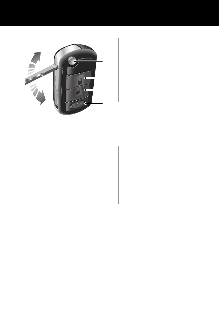
THE REMOTE CONTROL
LAN0114G
1. Key release button.
Press to release the folded key.
2. Lock button.
Locks all doors and activates perimetric
alarm.
See Perimetric alarm, 47.
3. Unlock button.
Press once to disarm all alarm features and
unlock driver’s door only. Press twice to
open all doors.
Note: The above applies unless configured
for multi-point entry.
See Single-point entry, 44.
4. Land Rover button.
The remote control can be programmed to
initiate one of 5 features; Panic alarm,
Headlamp courtesy delay, Tailgate release,
Tailglass release or Air suspension control.
See LAND ROVER BUTTON, 42.
Quick Start
Single point entry
This is a security feature that unlocks only the
driver’s door. It can be disabled on individual
1
2
3
4
remote controls by simultaneously pressing
and holding buttons 2 and 3 for three
seconds. The vehicle will lock and then
unlock in the currently selected mode to
confirm the change.
You can now unlock all doors with a single
press. Repeating the procedure will re-enable
Single point entry.
Automatic relock
If the vehicle is unlocked with the remote
control, it will automatically relock and arm the
alarm if a door or the tailgate is not opened
within one minute.
Partial arming
If an aperture (door, hood or tailgate) is not
fully closed when the remote control lock
button is pressed, the horn will sound briefly
to signal that an aperture is still open. The
alarm will remain disarmed and all of the
closed apertures will lock.
As soon as the open aperture is closed, the
system will automatically arm, signalled by
three flashes of the hazard warning lamps.
7
Quick Start
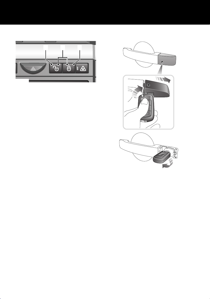
CENTRAL LOCKING
1 23
LAN0121N
Master lock and unlock switches
1. Press to unlock all doors and tailgate.
2. Press to lock all doors and tailgate.
3. Press both buttons simultaneously for
three seconds to release the tailgate.
Speed related locking
If enabled, the doors and tailgate will
automatically lock when the vehicle’s speed
exceeds 8 km/h (5 mph).
This feature can be disabled or enabled in the
SETTINGS menu of the trip computer.
See SELECTING SETTINGS OPTION, 86.
EMERGENCY UNLOCKING
LAN0116G
If the remote control should fail, there is an
emergency access feature on the left-hand front
door lock. With the key inserted into the slot
beneath the handle cap, the cap can be pulled
outwards slightly and then moved backwards to
unhook it. The key can now be used to unlock
the vehicle.
See Emergency locking/unlocking, 50.
8
Quick Start
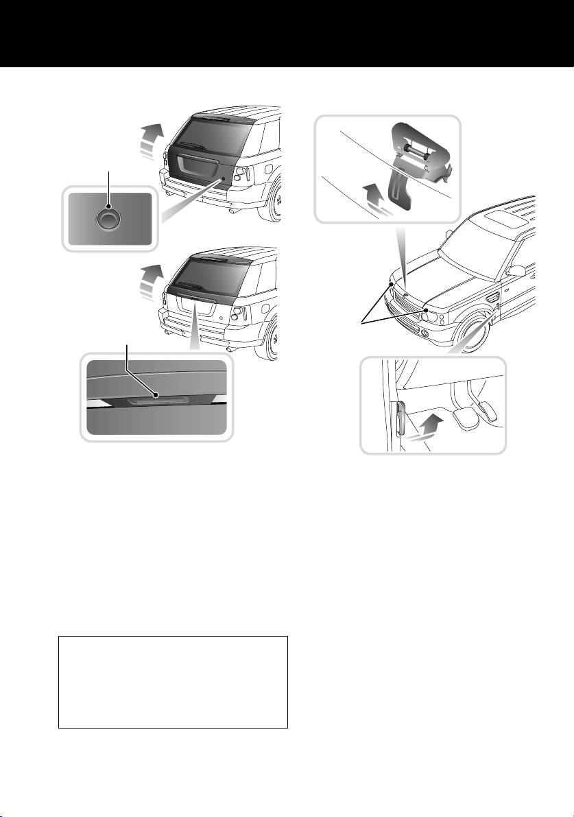
TAILGATE
1
2
LAN0394G
Opening the tailgate
With all the doors unlocked, press the release
button 1 on the tailgate to release.
The tailgate incorporates a ‘Power closure’
feature, which removes the need to ‘slam’ the
tailgate when closing.
Opening the tailglass
With all the doors unlocked, press the touch
pad 2 on the exterior handle and pull to open.
Operating note
If the vehicle is locked/unlocked 10 times
within a short period, the door and tailgate
latches will be disabled for approximately one
minute, to protect the battery and lock
mechanism.
HOOD
2
3
1
LAN0395G
Opening
Pull the hood release lever 1 located on the
left-hand side of the vehicle.
Lift the hood safety catch lever 2, located on the
front edge of the hood beneath the center point
of the words LAND ROVER and raise the hood.
Closing
Lower the hood until it is 300 mm (12 inches)
from its closed position. Using the palms of
both hands positioned on the front edge of the
hood on either side of the radiator grille, push
down until the catches ‘click’.
Check that both catches 3 are engaged by trying
to lift the front edge of the hood.
9
Quick Start
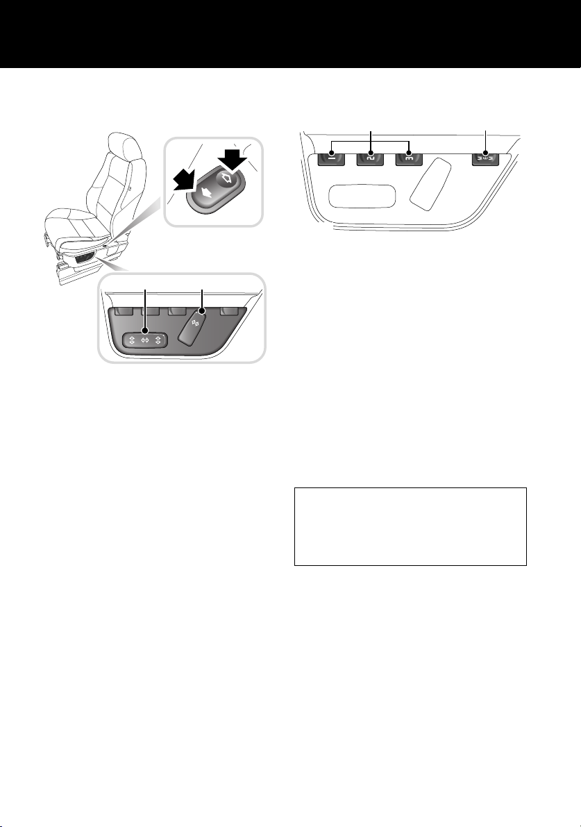
SEAT ADJUSTMENT - POWER SEATS
(Driver’s seat only)
3
1
LAN0396G
To adjust the seats, the starter switch must be
in position I or II.
1. Seat recline.
2. Seat fore/aft, cushion height and front tilt
control.
3. Lower backrest lumbar support.
Power operated memory driver’s seat also has
a 10 minute active period (Non-memory power
operated seats up to 15 minutes) initiated
when:
• The driver’s door is opened/closed.
• The starter key is turned to the off position.
See FRONT SEAT ADJUSTMENT, 55.
2
DRIVING POSITION MEMORY
2
LAN0397G
Once you have adjusted the driver’s seat and
exterior mirrors, the vehicle can memorise
these settings for future use.
1. Press the memory store button 1 to
activate the memory function for five
seconds.
2. Press one of the preset buttons 2 within
five seconds to memorise the current
settings. MEMORY STORED will be
displayed in the message center
accompanied by an audible chime to
confirm the settings have been memorised.
To recall a stored driving position, press the
appropriate preset button 2.
Operating note
A seat position will only be memorised during
the five second active period.
Any existing settings will be over-written
when programming a memory position.
Lazy entry
When this feature is enabled, the vehicle stores
the seating and mirror positions for each
remote control. Next time the vehicle is
unlocked using a remote control, the position of
the seat and mirrors will adjust to the last used
position.
This feature can be disabled or enabled in the
Settings option accessed via the trip computer.
1
10
Quick Start
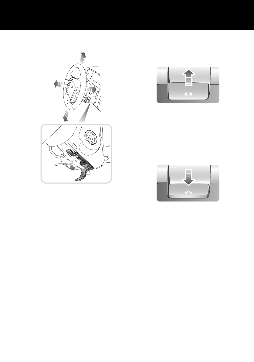
STEERING COLUMN ADJUSTMENT
LAN0398G
1. Move the lever located under the steering
wheel fully downward.
2. Adjust the height and reach of the steering
wheel to the desired position.
3. Move the lever fully up to lock the position
of the wheel.
See STEERING COLUMN ADJUSTMENT, 80.
PARKBRAKE (EPB)
Applying
LAN0406G
With the vehicle stationary, pull up the
parkbrake lever and release it. The lever will
return to a neutral position and the red warning
indicator in the instrument pack will illuminate.
Releasing
LAN0407G
The starter switch must be in position I or II.
Apply the footbrake and press down on the
parkbrake lever.
If the vehicle is stationary with the parkbrake
applied and either D (Drive) or R (Reverse)
selected, pressing the accelerator will
automatically release the parkbrake.
For more detailed information on the parkbrake,
see PARKBRAKE (EPB), 177.
11
Quick Start
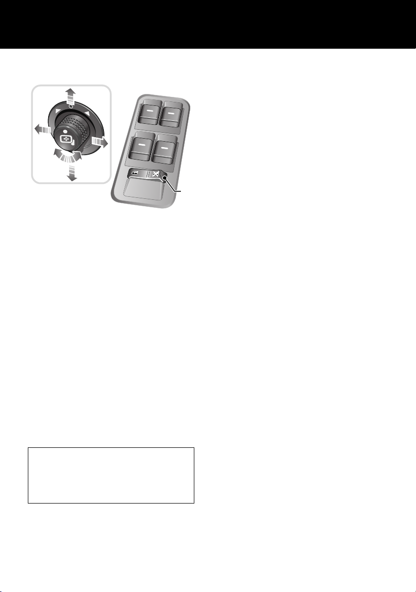
WINDOWS/DOOR MIRRORS
1
2
LAN0399G
Windows
• To open a window, press and hold the
respective switch.
• To close the window, pull and hold the
switch.
Window movement can be stopped at any time
by releasing the switch.
See ELECTRIC WINDOWS, 115.
One touch operation (front doors only)
Press/lift the switch briefly to open or close the
window in one movement. Window movement
can be stopped at any time by pressing the
switch again.
Rear window isolation switch
Press the right-hand side of switch 2 to inhibit
the operation of the rear window switches.
Door mirror adjustment
To adjust the mirrors, rotate the mirror
adjustment knob 1 left or right to select the
appropriate mirror. Move the knob in any
direction to adjust the position of the mirror
glass. See EXTERIOR MIRRORS, 81.
Reverse automatic mirror dip
With the feature enabled, when reverse gear is
selected the door mirrors will dip.
The dip position of the door mirrors can be
personalised. See Reverse mirror dipping, 82.
This feature can be disabled or enabled in the
Settings option accessed via the trip computer.
See SELECTING SETTINGS OPTION, 86.
Resonance with lowered windows
If a resonance/booming sound occurs when a
rear window is open, lowering an adjacent
front window about 25 mm (1 inch) will
eliminate the condition.
12
Quick Start
SEAT BELTS/CHILD RESTRAINTS
A warning indicator in the
instrument pack will illuminate to
alert you that the driver’s and/or
front passenger’s seat belt is unbuckled. An
intermittent chime may also be heard.
Automatic Locking Reels (ALR)
All passenger seat belts have ALR fitted for use
with child seats or securing large items.
• To engage: extend seat belt to maximum
length to enable locking mechanism.
• Allow seat belt to retract onto the child
seat/large item (a clicking sound will be
heard as the belt retracts). Ensure there is
no slack by pressing the seat/item firmly
into the vehicle seat.
• To disengage: unbuckle belt and allow belt
to fully retract.
With ALR enabled, as the seat belt retracts, it
will automatically lock, preventing
re-extension.
Ensure passengers do not fully extend the
restraints and inadvertently engage this
feature during normal use.
Child Seats
It is important to remember that the child’s
weight, rather than age, determines the type of
seat that is required.
See CHILD SEATS, 67.
Recommended child seat
Land Rover strongly recommends the use of
LATCH (Lower Anchors and Tethers for
CHildren) child seats.
LATCH child seats can only be fitted in the
rear, outer seating positions.
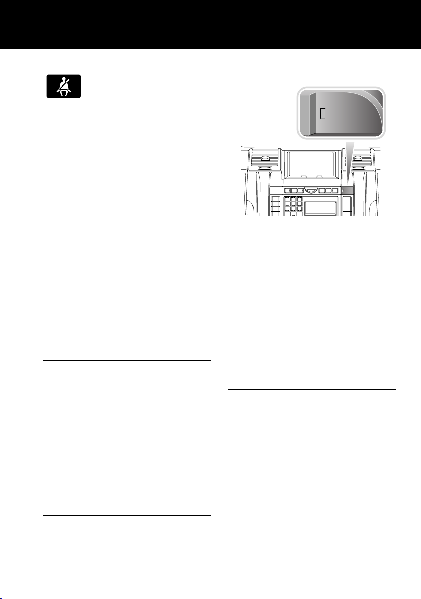
PASSENGER AIR BAG
PASS
AIRBAG
OFF
PASS
AIRBAG
123
ABC DEF
456
JKL MNOGHI
789
TUV WXYZPQRS
LAN0759N
0
The front passenger seat is fitted with an
occupancy detection system that determines
the state of seat occupancy and sets the air bag
status to suit.
• Seat unoccupied - air bag deactivated and
indicator off.
• Seat occupied - air bag activated and
indicator off.
• Seat occupied by a child seat or low weight
object - air bag deactivated and indicator
on.
See Occupant detection, 77.
Operating note
If the indicator becomes permanently
illuminated when the seat is definitely empty,
please contact your Land Rover Dealer
immediately.
OFF
6CD-465
13
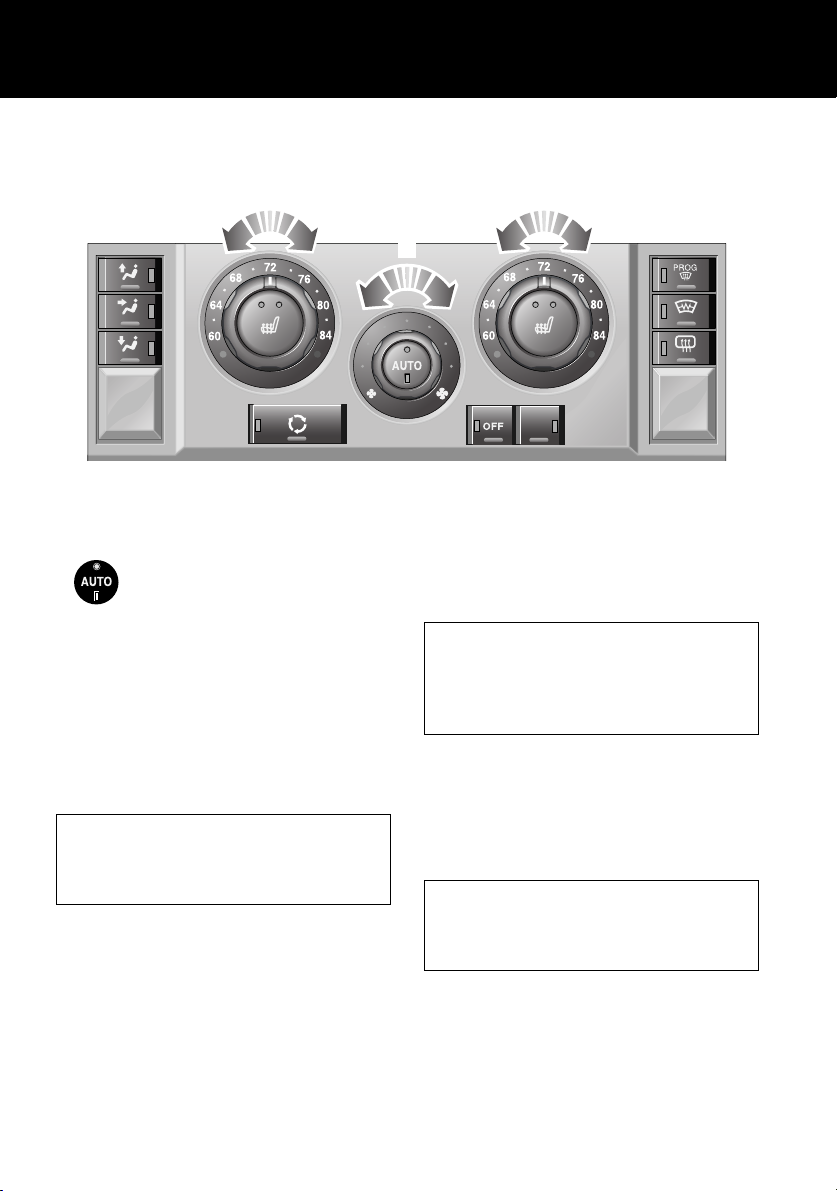
HEATING AND VENTILATION
Quick Start
1
LAN0762N
AUTO (Automatic) MODE
Press AUTO to select automatic
operation of the system, both
LEDs in the switch will illuminate.
The system adjusts heat output, blower speed,
air intake and airflow distribution to maintain
your the selected temperature(s) and reduce
misting without further adjustments.
Use the air distribution and blower controls to
adjust the automatic settings. The appropriate
LED in the AUTO control will extinguish.
Recommended mode
Select AUTO as the normal operating mode.
This will help prevent window misting and
odours from the climate control system.
Air conditioning
Air conditioning provides cooled and
dehumidified air for occupant comfort. Dry
airflow is effective in preventing misting of
windows and is also beneficial at low external
temperatures.
1
2
ECON
Air conditioning is automatically switched on
and controlled whenever the system is not
operating in ‘Economy’ mode.
External water deposits
The air conditioning system removes
moisture from the air and deposits excess
water beneath the vehicle. Puddles may form,
but this is normal and no cause for concern.
Temperature selection
Rotate the controls 1 to adjust the temperature
for the respective side of the passenger
compartment.
Operating note
It is not possible to achieve a temperature
differential of more than 4°C (7°F) between
left and right.
14
Quick Start
Blower speed
Rotate the control 2 to adjust the airflow. LEDs
will illuminate to indicate which of the eight
possible speeds is currently selected.
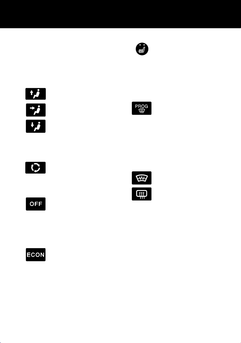
Air distribution control
Press to select a distribution setting. An LED
will illuminate in the switch.
Windshield and side window vents
Face level vents
Foot level vents
More than one setting can be selected.
Air recirculation
Press to activate air recirculation.
An LED will illuminate in the
switch. Press again to return to
fresh air intake.
OFF
Press to switch the system off. An
LED will illuminate in the switch.
Press again to return the system to
its previous operating mode. The system will
also be reactivated by using the AUTO, blower
speed, air distribution or defrost controls.
Economy mode
Press to select ‘Economy’ mode.
An LED will illuminate in the
switch.
Air conditioning is switched off to reduce load
on the engine and improve fuel consumption.
Seat heaters
Press the relevant button to
operate the required seat heater at
high level. Both LEDs in the switch
will illuminate.
Press a second time to heat the seat at a lower
level. One LED will extinguish.
Press a third time to switch off.
Defrost mode
Press to remove frost or heavy
misting from the windshield. The
system will automatically adjust
the blower output for maximum
clearing, in addition the rear window and
windshield heaters will be activated.
Press again to switch off defrost mode. The rear
window and windshield heaters will remain on
for a preset interval.
Heated windshield/rear window
Press to operate. An LED will
illuminate in the switch.
The heaters will automatically
switch off after a preset interval.
For more information, see TEMPERATURE
CONTROLS, 119.
15
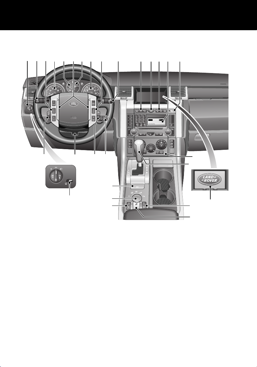
FACIA CONTROLS
Quick Start
1 2 3 4 6 7 8 9
A
U
T
O
27
5
26
AUTO
28
LAN0111N
25
24
23
22
21
10 11
123
456
789
ABC DEF
JKL MNOGHI
TUV WXYZPQRS
0
12 13
CD 3 14 : 54
2Tr 15:43
123456
14
15
6CD-465
16
17
18
19
20
16

Quick Start
FACIA CONTROLS KEY
1. Lamps master switch
2. High beam/Direction indicators/Trip
computer
3. Cruise control switches
4. Tachometer
5. Temperature gauge
6. Horn buttons
7. Fuel gauge
8. Speedometer
9. Audio/Telephone remote controls
10. Wiper/washer controls
11. Dynamic Stability Control (DSC) switch
12. Hazard warning lamp switch
13. Door lock/unlock switches
14. Audio display/controls
15. Passenger air bag status indicator
16. Heater/Air conditioning controls
17. Gear selector
18. Display screen
19. Transfer gearbox switch
20. Hill Descent Control (HDC) switch
21. Air suspension switch
22. Terrain Response
23. Electric parkbrake (EPB) switch
24. Starter switch
25. Telephone switch
26. Steering column adjustment
27. Voice recognition switch
28. Dimmer control
TM
control switch
17
Quick Start
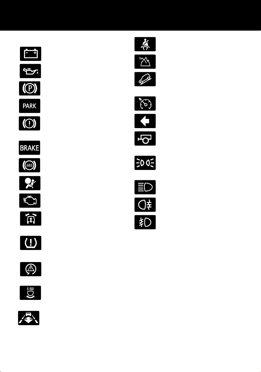
WARNING INDICATORS
Battery charging - RED.
Low oil pressure - RED.
Parkbrake - RED (Canada only).
Parkbrake - RED (U.S. only).
Brakes - RED/AMBER
(Canada only).
Brakes - RED/AMBER (U.S.only).
Anti-lock braking system - AMBER.
Air bag - RED.
Engine - AMBER.
Suspension/Dynamic response RED/AMBER.
Seat belts - RED.
Low gear range selected - GREEN.
Hill Descent Control (HDC) on GREEN.
Cruise control active - AMBER.
Direction indicator - GREEN.
Trailer direction indicator GREEN.
Side lamps/Headlamps on GREEN.
Headlamp high beam on - BLUE.
Rear fog lamps on - AMBER.
Front fog lamps on - GREEN.
Low tire pressure - AMBER.
Dynamic Stability Control (DSC) AMBER.
Adaptive front lighting system AMBER.
Adaptive Cruise Control (ACC) AMBER.
If a red warning indicator illuminates while
driving, a serious fault is indicated. Stop the
vehicle and refer to the main section of this
handbook.
For a full description of warning indicators and
their functions, see Warning Indicators, 100.
18
Quick Start
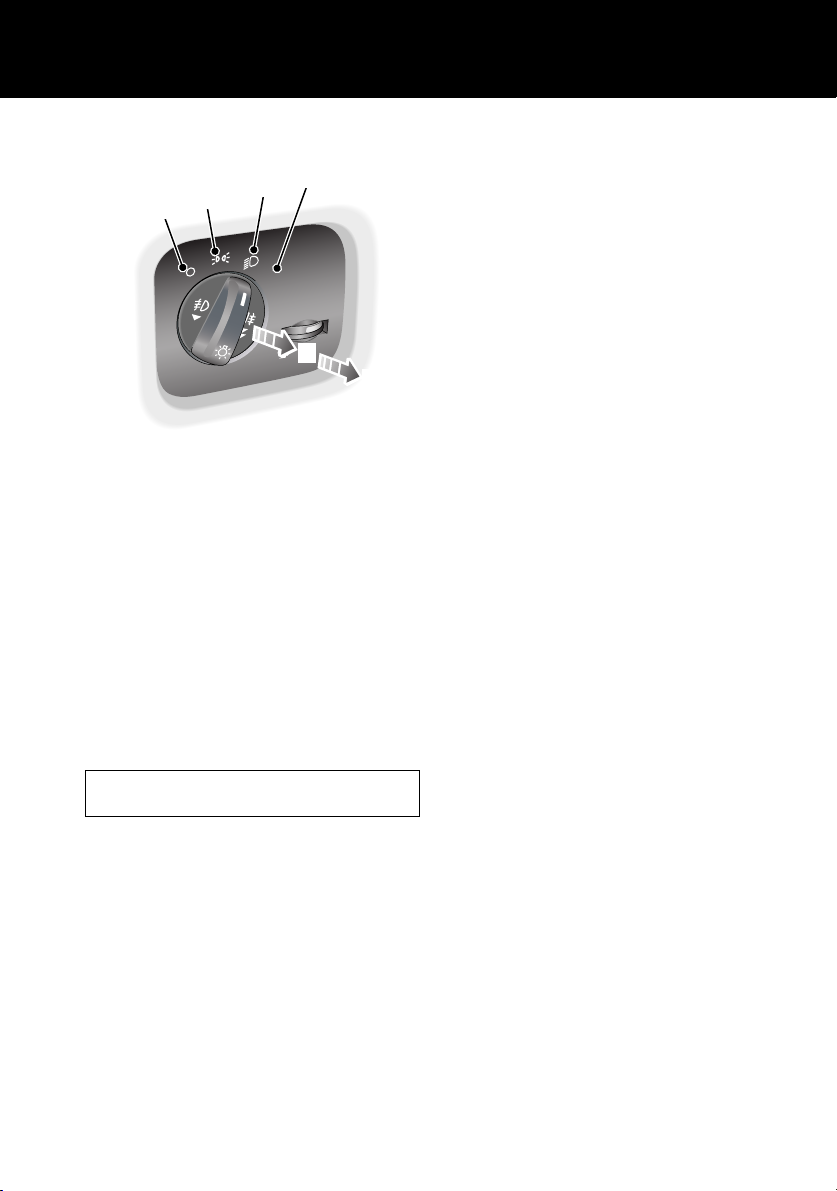
LAMPS MASTER SWITCH
4
3
2
1
O
T
AU
5
LAN0403G
1. Side lamps and headlamps off.
2. Side lamps on.
3. Low beam headlamps on.
4. Automatic control lamps on.
In AUTO mode and the starter switch in
position II, a sensor monitors the exterior
light levels and will automatically switch
the side lamps and low beam headlamps
on or off as required.
5. Front fog lamps on.
6. Front and rear fog lamps on.
Headlamp courtesy delay
With the master switch in positions 2, 3 or 4,
turn the starter switch off and remove the key.
Turn the master switch to the off position. The
headlamps will remain on for up to 240
seconds. For a full description of this feature
and how to set the time delay, see Headlamp
courtesy delay, 43.
6
Fog lamps cannot be operated if the lamps
master switch is at position 4 Auto.
For a full description of these functions, see
EXTERIOR LAMPS, 107.
19
Quick Start
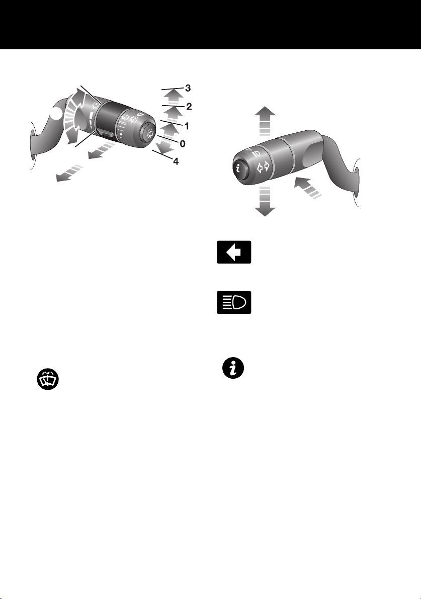
STEERING COLUMN LEVERS
5
6
7
LAN0519G
1. Rain sensor variable delay wipe.
2. Normal speed wipe.
3. Fast speed wipe.
4. Single wipe.
5. Rotate collar to adjust rain sensor variable
delay.
Rear wiper and washer
Pull the lever to position 6 for intermittent
operation of the rear wiper. Pull and hold the
lever in position 7 to operate the rear washer
and wiper.
Windshield washer
Push the button on the end of the
lever to operate the wndscreen
washer.
For more detailed information on the wash/wipe
system, see WINDSHIELD WIPERS, 110.
Direction/turn indicators/Headlamp high
beam
LAN0405G
Move the lever up or down to
activate the direction/turn
indicators.
Push the lever away from you to
select headlamp high beam. A
blue warning indicator will
illuminate on the instument pack.
Trip computer
Press the button on the end of the
lever to cycle through the trip
computer functions displayed on
the message center.
See TRIP COMPUTER -
FUNCTION SELECTION, 85
20

Quick Start
CONFIGURABLE FEATURES
Settings options (trip computer)
These are displayed on the main message center. See SELECTING SETTINGS OPTION, 86.
SETTINGS CHOICE
TRIP DISTANCE UNITS (odometer) MILES/KM
FUEL USAGE UNITS MPG
l/100km
Km/l
o
EXTERNAL TEMPERATURE
OVERSPEED WARNING
(Set a personal speed limit - Warnings are
displayed in the message center)
HEADLAMP OFF DELAY 30/60/120/240 seconds
AUTO DOOR LOCK (speed related locking) ON/OFF
REVERSE MIRROR DIP ON/OFF
LAZY ENTRY ON/OFF
RESTORE DEFAULT SETTINGS YES/NO
C or oF
Off
20 - 250 km/h or 15 to 140 mph in 5-unit steps
(units set as trip distance)
Remote control
The remote control can be configured to
operate the following features:
• Panic alarm, for personal protection. See
Panic alarm, 43.
• Headlamp courtesy delay, providing
lighting for personal safety. See Headlamp
courtesy delay, 43.
• Air suspension control, allows remote
operation of the air suspension. See Air
suspension control, 44.
• Tailgate release function, releases the
tailgate as a whole. See Tailgate release,
45.
• Tailglass release function, releases only the
tailglass. See Tailglass release, 45.
• Single point entry, allowing only the drivers
door to be opened remotely. See
Single-point entry, 44.
Daytime running lamps
Unless prevented by legislation, it is possible to
automatically switch on the exterior lamps
whenever the engine is running. See Daytime
running lamps, 108.
Speed dependent wiper mode
The wiper speed in all modes can be
automatically varied according to vehicle
speed. See Speed-dependent mode, 111.
21
Quick Start
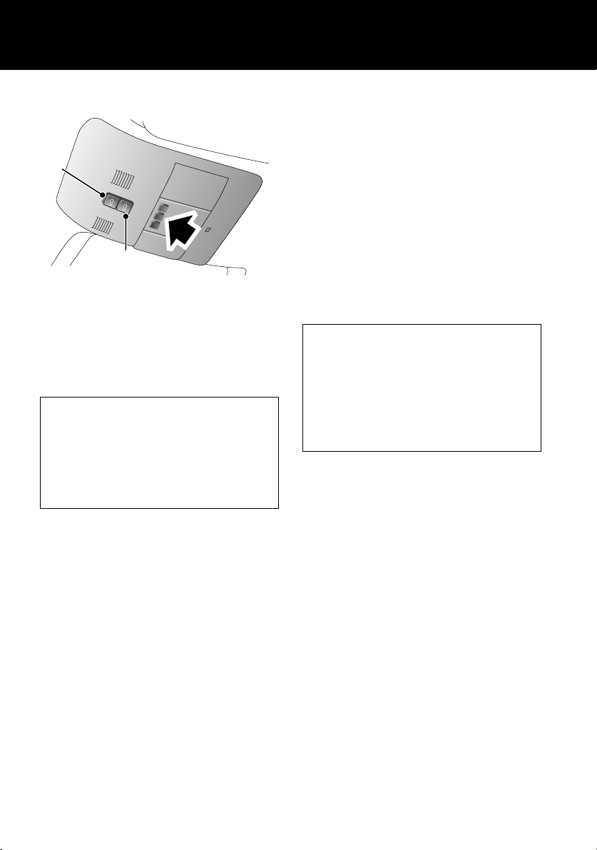
OVERHEAD CONSOLE
1
2
LAN0401G
Courtesy lamps
If automatic mode is enabled, the front and rear
courtesy lamps will operate in conjunction with
the vehicle being unlocked/locked or when a
door is opened.
Automatic mode
Automatic mode for the courtesy lamps can
be enabled/disabled by pressing and holding
the center lamp switch for more than three
seconds.
A message will be displayed in the message
center advising you of the mode currently set.
Sunroof
Open/close sunroof:
• Press and release the switch 1 to open the
sunroof fully.
• Press the switch 2 to close.
Tilt sunroof:
• Press and release the switch 2 to open the
sunroof to the tilt position.
• Press and hold the switch 1 to close.
If the sunroof is moving, it can be stopped by
pressing the swich again.
See SUNROOF OPERATION, 117.
Operating note
The sunroof can be operated with the starter
key in position I or II and for 40 seconds after
position 0 has been selected, providing that
neither front door has been opened.
With the starter key in position I or 0, the
switch will need to be pressed and held until
the roof reaches the desired position.
The courtesy lamps can be manually switched
on/off by pressing and releasing the center
lamp switch (arrowed in illustration).
See Front interior lamps, 127.
Interior lamps
The interior lamps can be switched on/off by
pressing the switch adjacent to the lamp.
22
Quick Start
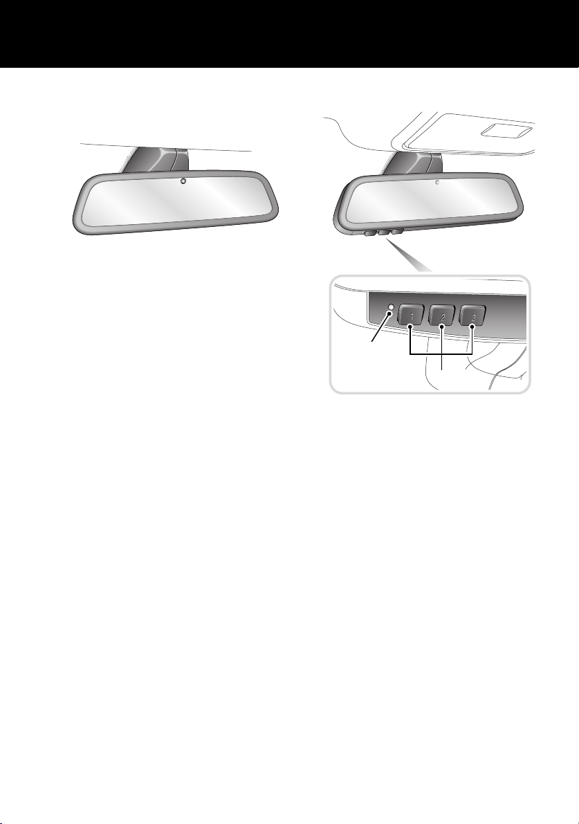
REAR VIEW MIRROR
Automatic dimming
LAN0231G
Rear view mirrors are fitted with a feature that
will automatically darken to counteract glare
from the headlamps of a following vehicle.
This feature is temporarily switched off while
reverse gear is selected.
See REAR-VIEW MIRROR, 133.
HOMELINK® TRANSMITTER
1
2
H6480N
1. Status indicator light
Red - transmitter
Green - auto dimming
2. Channel buttons
The buttons 2 can be programmed to transmit
radio frequencies that can operate external
devices i.e. garage doors, entry gates, security
systems etc.
See HOMELINK® TRANSMITTER, 140.
23
Quick Start
AUTOMATIC TRANSMISSION
Gearshift interlock
The starter switch must be in position II, the
foot brake applied and the selector release
button pressed before the gear selector can be
moved from P (Park) to R (Reverse).
The gear selector must be in P before the starter
key can be removed.
See AUTOMATIC TRANSMISSION USE, 157.
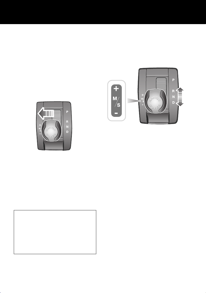
Sport mode
LAN0408G
In Sport mode, automatic gear changing is
maintained but the gearshift changes are
modified to improve performance.
To select Sport mode, move the gear selector
from D towards the left-hand side of the vehicle.
The word SPORT will appear in the instrument
pack display and the LED in the gear selector
surround will illuminate.
With the gear selector in Sport, the
transmission will stay in lower gears for
longer with downshifts occurring more
readily.
Fuel consumption will be adversely affected.
When using Terrain Response, Sport mode is
only available if the General program is
selected.
CommandShift
CommandShift gear selection can be used as
an alternative to automatic gear selection and is
particularly effective when rapid acceleration or
engine braking is required.
LAN0422G
1. Select Sport mode. The transmission will
automatically select the gear most
appropriate to the vehicle’s road speed and
accelerator position.
2. Moving the selector lever forward (+) or
backward (-) and then releasing will
manually select a higher or lower gear
(when available). The message
TRANSMISSION COMMANDSHIFT
SELECTED will appear in the message
center.
3. Subsequent gear selections will shown in
the instrument pack display.
4. To deselect CommandShift mode, move
the selector lever back to D.
24
Quick Start
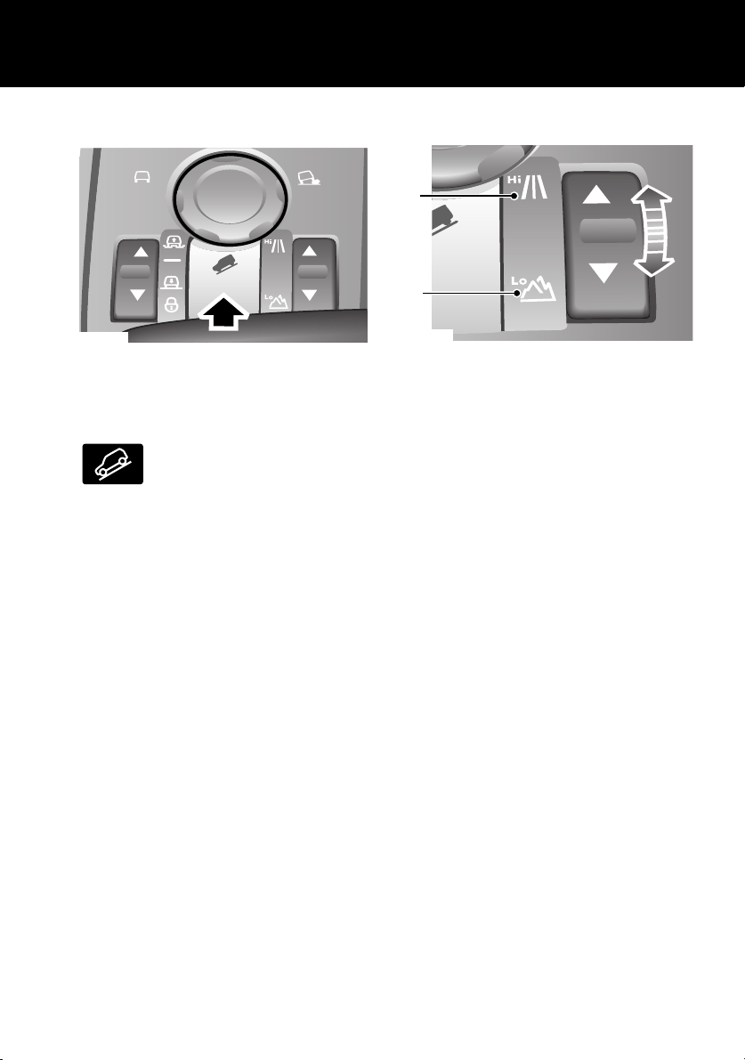
HILL DESCENT CONTROL (HDC)
LAN0263G
HDC operates in conjunction with the anti-lock
braking system to provide greater control in
off-road situations, particularly when
descending severe gradients.
Press the switch (arrowed in
illustration) to select HDC. HDC
can be selected at speeds below
80 km/h (50 mph), but will not be fully active
until the vehicle speed reduces below 50 km/h
(30 mph), confirmed by a continuously
illuminated HDC indicator in the instrument
pack.
Press the switch again to deselect HDC.
See HILL DESCENT CONTROL (HDC), 181.
TRANSFER GEARBOX
1
2
LAN0424G
1. HIGH range should be used for all normal
road driving and also for off-road driving
across dry level terrain.
2. LOW range should be used in situations
where low speed manoeuvring is
necessary, or in extreme off-road
conditions.
Range changing
The recommended method for range changing
is with the vehicle stationary. With the engine
running and the main gearbox in N (Neutral),
press and release the front/rear of the transfer
gearbox switch to select the range required.
The indicators on the switch and instrument
pack display will flash during range changing.
When range changing is complete, a chime will
sound and a message displayed in the message
center.
See TRANSFER GEARBOX, 162.
25
Quick Start
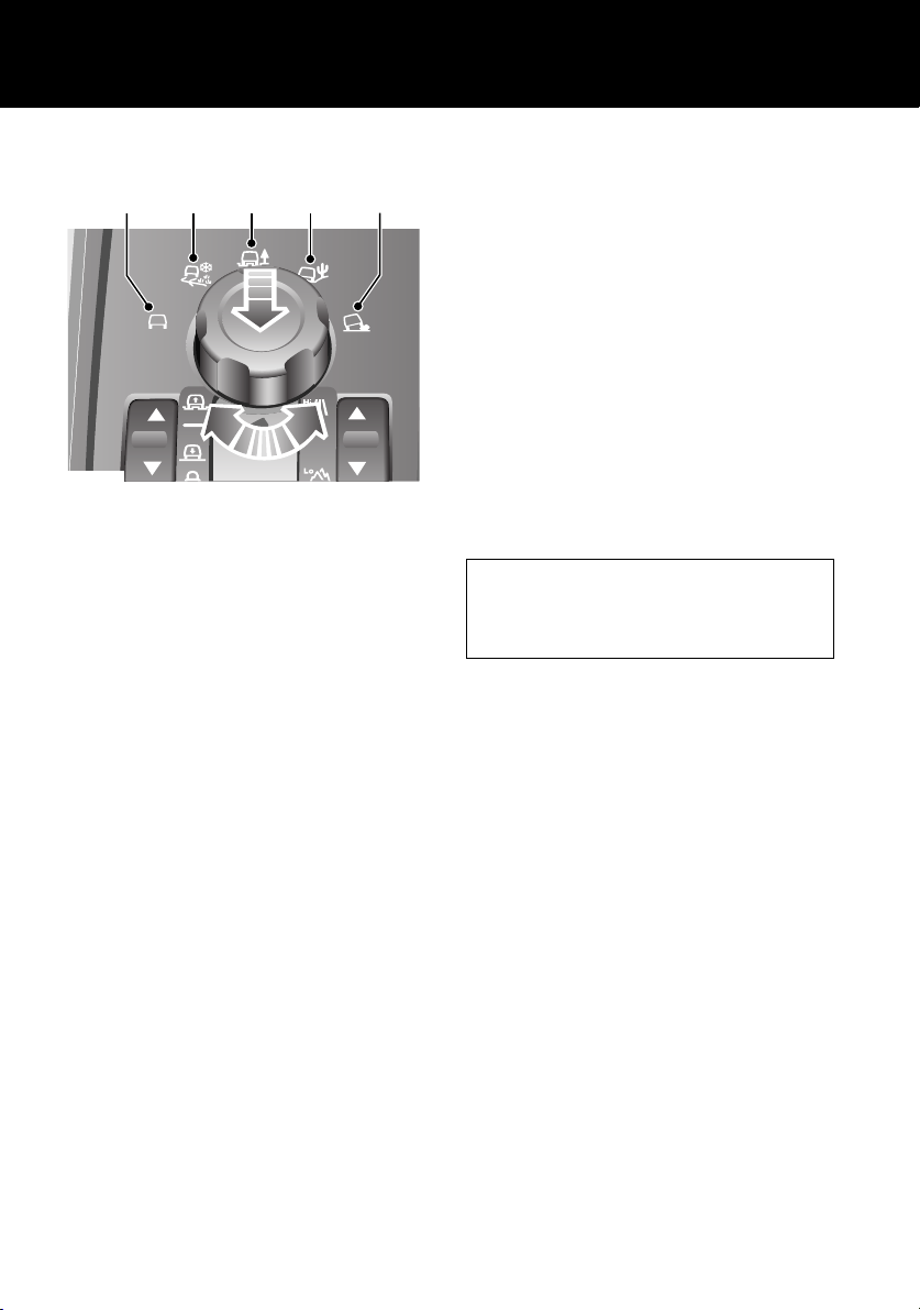
TERRAIN RESPONSE SYSTEM
1
LAN0426G
1. General: Suitable for surfaces that match
typical road surfaces.
2. Grass-Gravel-Snow: Suitable for surfaces
which are firm, but have a slippery surface,
e.g. grass, snow, loose gravel, pebbles or
icy conditions.
3. Mud-Ruts: Suitable for soft, muddy,
uneven or deeply rutted ground. It is
recommended that LOW range is selected
on the Transfer gearbox.
4. Sand: Suitable for soft, predominantly dry,
yielding sandy ground, e.g. sand dunes and
deserts. If the sand is damp or wet, the
Mud-Ruts program may be more
beneficial.
5. Rock Crawl: Only selectable when the
Transfer gearbox is in LOW range. Suitable
for crossing wet or dry, solid unyielding
ground requiring high levels of wheel
displacement, e.g. clusters of boulders or
rocky river beds.
See TERRAIN RESPONSE, 191.
2
4
3
5
The Terrain Response system is always active
and cannot be switched off. When the vehicle is
started, the system will normally start in its
General program.
To raise the rotary knob, press down lightly and
release. Manual selection of a special program,
by rotating the knob, will provide benefits in
how the vehicle can be driven over different
surfaces or terrains by automatically adjusting
the vehicle’s drive and suspension systems.
It is recommended that a special program be
engaged whenever driving conditions could
become difficult and cancelled once the
conditions for use are no longer present. To
lower the rotary knob press down until a ‘click’
is heard.
Wading
When driving through water less than 490
mm (19 inches) deep, select the program
suitable for the surface beneath the water.
26
Quick Start
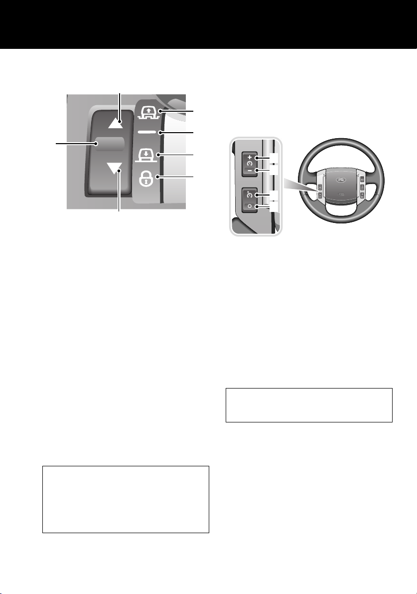
AIR SUSPENSION
2
3
4
1
5
6
LAN0271G
Vehicle height can be manually adjusted via the
raise/lower switch 1. Height changes may only
be made when the the engine is running and the
driver and passenger doors are closed.
Indicators 2 or 7 will illuminate to show the
direction of movement. They extinguish when
the height change is complete.
Off-road height 3, provides improved ground
clearance and approach, departure and
break-over angles.
On-road height 4, is the normal height for the
vehicle.
Access height 5, lowers the vehicle to provide
easier entry, exit and loading of the vehicle. This
position may be selected up to 40 seconds after
the starter switch is turned off.
Crawl (locked at Access height) 6, allows the
vehicle to be driven at low speeds at access
height, to give increased roof clearance.
7
See AIR SUSPENSION, 184.
CRUISE CONTROL
Cruise control enables the driver to maintain a
constant road speed without using the
accelerator pedal.
4
3
2
1
LAN0252G
1. CANCEL: cancel cruise control, but retains
the set speed in memory.
2. RESUME: resumes a SET speed retained in
memory.
3. SET - : to set a road speed or decrease the
speed in 2 km/h (1 mph) steps when cruise
control is operating.
4. SET + : to set a road speed or increase the
speed in 2 km/h (1 mph) steps when cruise
control is operating.
Cruise control will automatically disengage
when the brake pedal is used or when the
vehicle speed falls below 30 km/h (18 mph).
See CRUISE CONTROL, 165.
Vehicle height will be automatically adjusted
according to road speed in order to maintain
driveability and handling.
If Terrain Response is fitted, some of its
programs will automatically adjust the
suspension height.
27
Quick Start
AUDIO SYSTEM OPERATION
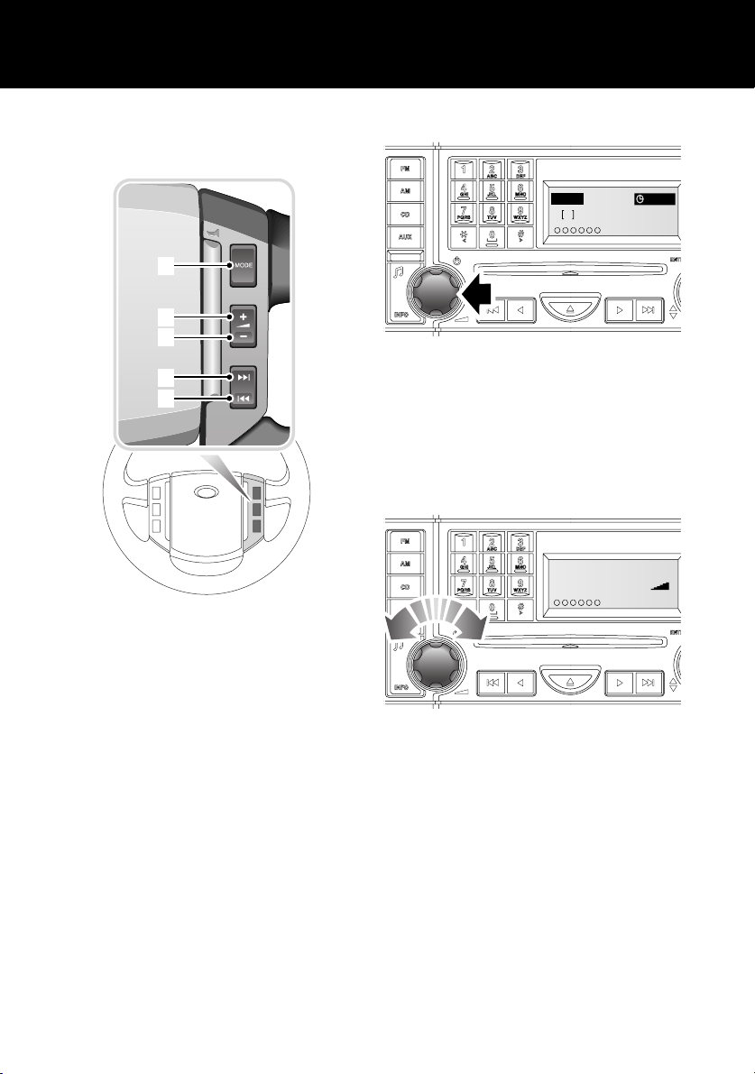
Steering wheel controls
1
2
3
4
5
ICE1579 ENG
1. Mode select
2. Volume up
3. Volume down
4. Channel up
5. Channel down
Switching on the audio unit
FM 14 : 54
2
107.9
123456
ICE1911 NAS
KSAN FM
To turn on the audio unit, press the rotary
control.
To make any of the changes to settings, as
shown in the following pages, the unit must be
switched on.
Volume control
Audio Volume
16
123456
ICE1615 ENG
ICE 1615
To increase or decrease the volume level, rotate
the control.
With the engine running, the volume level can
be adjusted between 0 and 35. If the audio unit
is turned off, it will re-start at the previously
selected volume level, provided that this is not
too loud or too quiet.
28
Quick Start
I
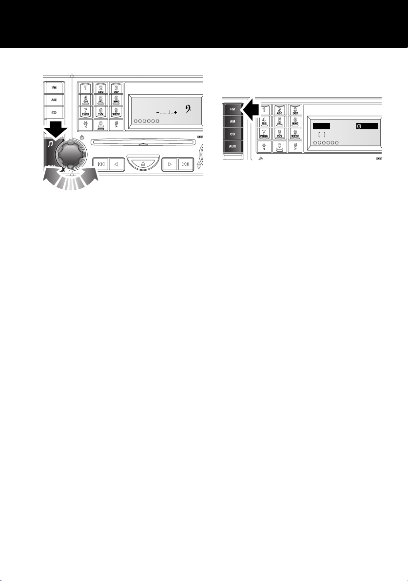
Tone and balance settings
Bass
123456
ICE1618 ENG
To change the Bass, Treble, Balance, Fader,
Subwoofer and Logic 7 settings, press the Tone
button (arrowed) repeatedly until the required
setting is displayed, then use the rotary control
to adjust the setting as required.
For further information, see TONE AND
BALANCE ADJUSTMENT, 299.
RADIO OPERATION
Autostore
FMA 14 : 54
106.5
2
123456
CE2135 NAS
To autostore FM or AM stations, press and hold
the FM or AM buttons. Autostore will be shown
in the information display and the stations will
be stored under the pre-set numbers, in the
order that they are found.
To access the stations once stored, press the
required pre-set number briefly.
Autostore
29
Quick Start
789
TUV WXYZPQRS
0
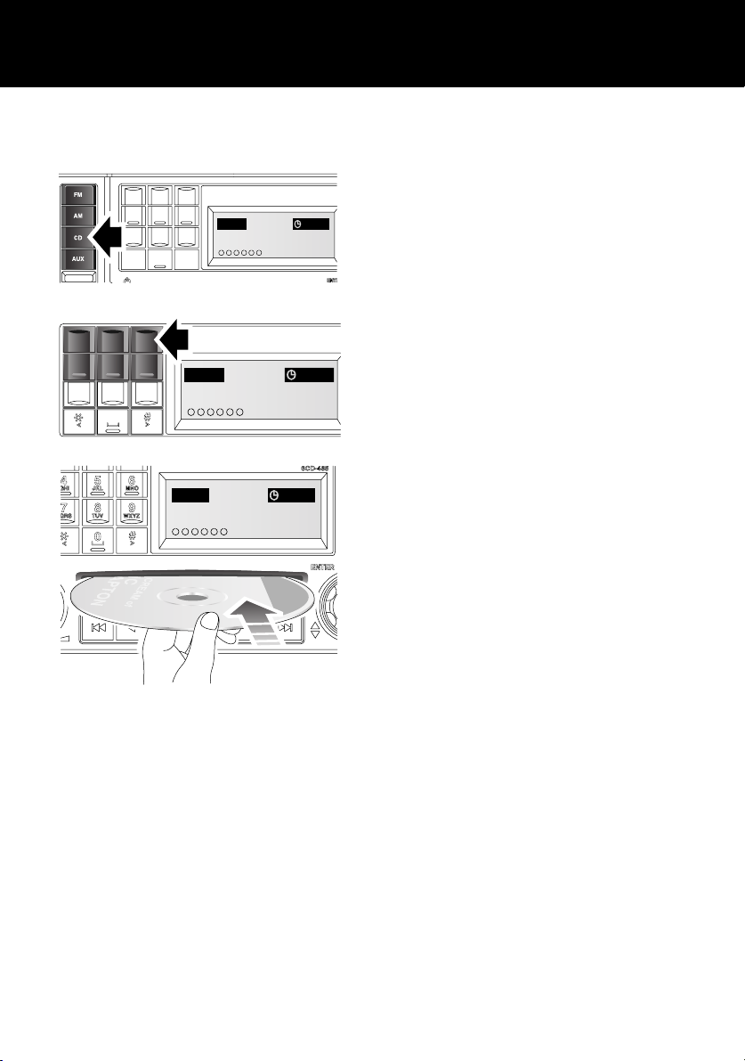
CD OPERATION
Inserting a CD
123
ABC DEF
456
JKL MNOGHI
CD 14 : 54
No Discs
Press 1-6
CD 3 14 : 54
Please Wait
CD 3 14 : 54
Disc
Insert
When inserting a disc into either player, ensure
that the label side of the disc is facing upwards
and present the disc to the slot. Do not push it
into the slot, the player mechanism will draw
the disc in automatically.
There will be a short pause whilst the player
reads the information from the disc, which will
then be displayed on the screen. Play will
commence at the first track on the newly
inserted disc.
Dual and DVDPlus discs
Please be aware that a new generation of DVD
discs is being adopted by the music industry.
They are known as Dual Discs or DVDPlus
discs. They have digital music on one side and
video content on the other. Current in-car audio
systems with a front loading CD player may
load and play this type of disc, however, it is
likely that the disc will not eject and will block
up the player. Such damage to a CD player will
not be covered under warranty.
ICE1875 ENG
Before inserting a CD into the audio unit, select
CD mode by pressing the CD button.
Note: It is necessary to then select an empty CD
slot, by pressing the appropriate disc selection
button (e.g. 3). The six circles at the bottom
left-hand side of the screen represent the six
available CD slots. As soon as one has a CD in
it, its number will appear in the circle. Empty
slots are, therefore, those without numbers.
30
 Loading...