

Page 1

Allen-Bradley
Dataliner DL5
Series Off-line
ALLEN-BRADLEY
User
Programming
Software
(Cat. No. 2706-NP5)
Manual
Page 2

Important User Information
Solid state equipment has operational characteristics differing from those of
electromechanical equipment. “Safety Guidelines for the Application,
Installation and Maintenance of Solid State Controls” (Publication SGI-1.1)
describes some important differences between solid state equipment and
hard–wired electromechanical devices. Because of this difference, and also
because of the wide variety of uses for solid state equipment, all persons
responsible for applying this equipment must satisfy themselves that each
intended application of this equipment is acceptable.
In no event will the Allen-Bradley Company be responsible or liable for
indirect or consequential damages resulting from the use or application of
this equipment.
The examples and diagrams in this manual are included solely for illustrative
purposes. Because of the many variables and requirements associated with
any particular installation, the Allen-Bradley Company cannot assume
responsibility or liability for actual use based on the examples and diagrams.
No patent liability is assumed by Allen-Bradley Company with respect to use
of information, circuits, equipment, or software described in this manual.
Reproduction of the contents of this manual, in whole or in part, without
written permission of the Allen-Bradley Company is prohibited.
Throughout this manual we use notes to make you aware of safety
considerations.
ATTENTION: Identifies information about practices or
circumstances that can lead to personal injury or death, property
!
damage, or economic loss.
Attentions help you:
• identify a hazard
• avoid the hazard
• recognize the consequences
Important: Identifies information that is especially important for successful
application and understanding of the product.
Dataliner is a registered trademark of Allen-Bradley Company, Inc.
Page 3

Table of Contents
DL5 Programming Software
User Manual
A–B
Using This Manual
Installing the Software
Cabling Information
Chapter 1
Overview of this Manual 1–1. . . . . . . . . . . . . . . . . . . . . . . . . . . . . . . . . . . .
Contents 1–1. . . . . . . . . . . . . . . . . . . . . . . . . . . . . . . . . . . . . . . . . . . . . . . . .
Intended Audience 1–1. . . . . . . . . . . . . . . . . . . . . . . . . . . . . . . . . . . . . . . . .
Conventions 1–2. . . . . . . . . . . . . . . . . . . . . . . . . . . . . . . . . . . . . . . . . . . . . .
Chapter 2
Chapter Objectives 2–1. . . . . . . . . . . . . . . . . . . . . . . . . . . . . . . . . . . . . . . . .
Before You Begin 2–1. . . . . . . . . . . . . . . . . . . . . . . . . . . . . . . . . . . . . . . . .
Installing DL5.EXE 2–1. . . . . . . . . . . . . . . . . . . . . . . . . . . . . . . . . . . . . . . .
Systems With 1 Hard and 1 Floppy or Micro Disk Drive 2–2. . . . . . . . . . .
Systems With 1 Floppy or Micro Disk Drive 2–3. . . . . . . . . . . . . . . . . . . .
Chapter 3
Chapter Objectives 3–1. . . . . . . . . . . . . . . . . . . . . . . . . . . . . . . . . . . . . . . . .
Cabling Information 3–1. . . . . . . . . . . . . . . . . . . . . . . . . . . . . . . . . . . . . . .
Abbreviations 3–2. . . . . . . . . . . . . . . . . . . . . . . . . . . . . . . . . . . . . . . . . . . . .
Catalog No. 2706-NC12 Serial Cable 3–2. . . . . . . . . . . . . . . . . . . . . . . . . .
Catalog No. 2706-NC13 Serial Cable 3–3. . . . . . . . . . . . . . . . . . . . . . . . . .
Catalog No. 2706-NC14 Serial Cable 3–3. . . . . . . . . . . . . . . . . . . . . . . . . .
Catalog No. 2706-NC15 Serial Cable 3–4. . . . . . . . . . . . . . . . . . . . . . . . . .
Running DL5 Off-line Programmer
Chapter 4
Chapter Objectives 4–1. . . . . . . . . . . . . . . . . . . . . . . . . . . . . . . . . . . . . . . . .
Initial Start Up 4–1. . . . . . . . . . . . . . . . . . . . . . . . . . . . . . . . . . . . . . . . . . . .
The Main Menu 4–2. . . . . . . . . . . . . . . . . . . . . . . . . . . . . . . . . . . . . . . . . . .
Option 1 Baud Rate Selection 4–3. . . . . . . . . . . . . . . . . . . . . . . . . . . . . . . .
Option 2 Terminal Mode 4–4. . . . . . . . . . . . . . . . . . . . . . . . . . . . . . . . . . . .
Option 3 Edit or Create Messages 4–5. . . . . . . . . . . . . . . . . . . . . . . . . . . . .
Naming a DL5 File 4–6. . . . . . . . . . . . . . . . . . . . . . . . . . . . . . . . . . . . . .
Creating a New Message 4–8. . . . . . . . . . . . . . . . . . . . . . . . . . . . . . . . .
Editing a DL5 File 4–12. . . . . . . . . . . . . . . . . . . . . . . . . . . . . . . . . . . . . .
Editing Existing Messages 4–14. . . . . . . . . . . . . . . . . . . . . . . . . . . . . . . .
F1 Help Screen 4–14. . . . . . . . . . . . . . . . . . . . . . . . . . . . . . . . . . . . . . . . .
Deleting All Files for a DL5 Name 4–15. . . . . . . . . . . . . . . . . . . . . . . . .
i
Page 4

Table of Contents
.
.
.
.A3.A
.B
.A4.B
DL5 Programming Software
User Manual
Running
DL5 Off-line Programmer
3.1
2
3
3
3
4
3
1
3
4
Chapter 4
Option 4 Edit Print File Functions 4–16. . . . . . . . . . . . . . . . . . . . . . . . . . . . .
Option 5 File Read / Write Functions 4–17. . . . . . . . . . . . . . . . . . . . . . . . . .
Read from DL5 Memory to Disk 4–18. . . . . . . . . . . . . . . . . . . . . . . . . . .
Write from a Disk to DL5 Memory 4–19. . . . . . . . . . . . . . . . . . . . . . . . .
Option 6 Exit to DOS 4–21. . . . . . . . . . . . . . . . . . . . . . . . . . . . . . . . . . . . . .
Figures
Catalog No. 2706-NC12 Cable 3–2. . . . . . . . . . . . . . . . . . . . . . . . . . . . .
Catalog No. 2706-NC13 Cable 3–3. . . . . . . . . . . . . . . . . . . . . . . . . . . . .
Catalog No. 2706-NC14 Cable 3–3. . . . . . . . . . . . . . . . . . . . . . . . . . . . .
Catalog No. 2706-NC15 Cable 3–4. . . . . . . . . . . . . . . . . . . . . . . . . . . . .
Tables
Chapter Descriptions 1–1. . . . . . . . . . . . . . . . . . . . . . . . . . . . . . . . . . . . .
DL5 Programming Cables 3–1. . . . . . . . . . . . . . . . . . . . . . . . . . . . . . . . .
Abbreviations 3–2. . . . . . . . . . . . . . . . . . . . . . . . . . . . . . . . . . . . . . . . . . .
DL5 Message Attributes 4–10. . . . . . . . . . . . . . . . . . . . . . . . . . . . . . . . . .
Display Special Functions 4–13. . . . . . . . . . . . . . . . . . . . . . . . . . . . . . . . .
ii
Page 5

Chapter
Overview of this Manual
Contents
A–B
1
Using this Manual
Read this chapter to familiarize yourself with the rest of the manual. You will
learn about:
• Contents of this manual
• Intended audience
• Conventions used
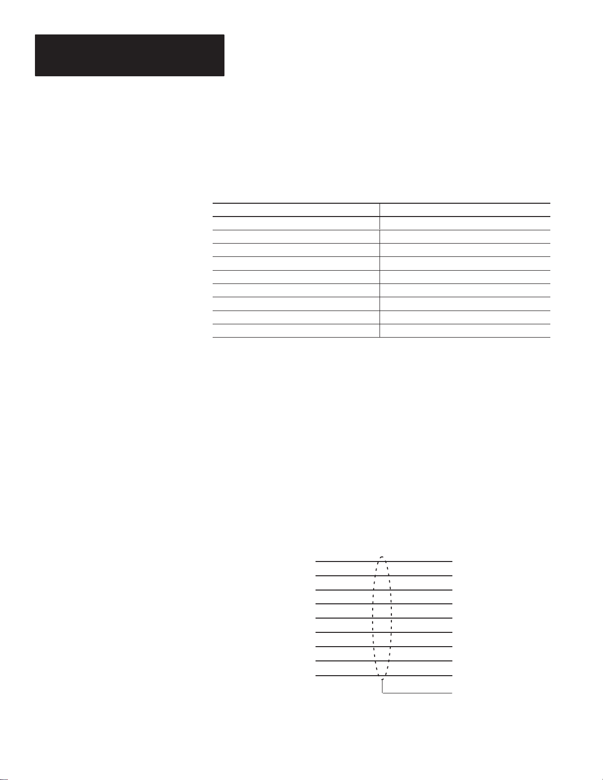
Table 1.A describes the chapters contained in this manual.
Table 1.A
Chapter Descriptions
Intended Audience
Chapter Title Purpose
1 Using this Manual Provides an overview of the manual.
Describes how to install DL5 off-line
2 Installing the Software
3 Cabling Information
4
No special knowledge is required to use this manual. The user should have
some familiarity with computer and communications terminology.
Running DL5 Off-line Programming
Software
programming software onto your
personal computer.
Describes the cable required to link the
DL5 to your off-line programming
computer.
Describes how to use the off-line
programming software.
1–1
Page 6
Chapter 1
Using this Manual
Conventions
In this manual, we use the following conventions.
• Screen displays are shown within a rectangular box. For example:
• Keys that you must press on your computer keyboard appear in
capitalized letters within brackets. For example:
Press [END] to return to main menu.
• References to an [ENTER] key refer to the carriage return function of
your keyboard and may appear on your keyboard as RETURN or
.
1–2
Page 7

Chapter
Installing DL5.EXE
Chapter Objectives
Before You Begin
A–B
2
Installing the Software
This chapter describes how to load the DL5 Off-line Programmer into your
personal computer.
The Off-line Programmer is software for programming DL5 Message
Displays. Using the Off-line Programmer is an efficient way to program
several DL5s with the same message set. The DL5 messages are created
using a personal computer and then downloaded to the display. You can also
receive (upload) messages from a DL5 that has already been programmed.
This software is menu driven with a new screen for each programming step.
It can be used with the following systems:
• Allen-Bradley 1784-T45, -T47, -T50, and -T60 Industrial Computers
• Allen-Bradley 6120 and 6121 Industrial Computers
• Most IBM PC AT and XT or compatible computers
Off-line programming software is supplied on both a 5 1/4 inch floppy disk
and a 3
Use this guide to get acquainted with the interactive programming software
to create and maintain your own library of DL5 message display programs.
This section shows you the procedure for installing the DL5 Off-line
Programmer on your computer. Read the following important information
before getting started on your system.
Important: This software is copyrighted but not copy protected. It is
recommended that you make a copy now and store the original disk in a safe
place. You will need a blank disk.
1
/2 inch micro disk. Be sure you have the disk that fits your system.
2–1
Page 8

Chapter 2
Installing DL5.EXE
stems
Installing the Software
Installation procedures are given for the following types of computers:
• Systems with 1 Hard and 1 Floppy (or micro) Disk Drive
• Systems with 2 Floppy (or micro) Disk Drives
• Systems with 1 Floppy (or micro) Disk Drive
Use the installation procedure for your type of system.
Sy
with
1 Hard and 1 Floppy
or Micro Disk Drive
Important: The recommended procedure for off-line programming on a
computer with one hard and one floppy or micro disk is to create a single
sub-directory that will store the DL5.EXE file.
Note: This installation procedure is for an IBM AT. Your computer will use
the same or similar prompts and responses.
1. Make sure DOS is ready and that you are working on the hard disk.
Normally the hard disk is the “C” drive, so the DOS prompt C: \ > is
displayed.
Note: Your DOS prompt could be different. See your computer’s DOS
manual.
2. Insert the DL5 off-line programming disk into the floppy drive.
Normally, this is the “A” drive.
3. Type:
4. At the DOS prompt (C: \ >) type:
MD \ DL5 [ENTER]
This step creates a sub-directory on the hard disk for the DL5 program
and files.
CD \ DL5 [ENTER]
2–2
This step puts you into the DL5 sub-directory. While you are in the DL5
sub-directory, your computer will usually give you the sub-directory DOS
prompt (C:\DL5>).
5. At the DOS prompt (C: \DL5>) type:
The Off-line Programmer is now installed on your hard disk in the DL5
sub-directory.
6. Remove the DL5 off-line programming disk from the “A” drive and store
it in a safe place.
7. At the sub-directory DOS prompt (C: \DL5>) type:
off-line programming will begin.
COPY A:DL5.EXE [ENTER]
DL5 [ENTER] and the
Page 9
Chapter 2
stems
Flopp
Installing the Software
Sy
with 1
or Micro Disk Drive
y
Note: This installation procedure is for an IBM AT. Your computer will use
the same or similar prompts and responses.
Important: The recommended way of using Off-line Programmer on a
computer with a single floppy or micro disk is to create a storage disk for
your DL5 files. Storing files on the DL5 off-line programming disk
restricts the number of files you can create.
ATTENTION: Before you begin this procedure, ”write protect”
your DOS disk by using a write protect tab. See your computer
!
user manual.
1. Insert your computer’s “write protected” DOS disk into the disk drive and
turn on the computer.
2. When the DOS prompt (A: \ >) is displayed, remove the DOS disk and
insert the DL5 off-line programming disk.
3. Type:
DL5 [ENTER]
The Off-line Programmer will begin.
4. Before you begin programming, remove the DL5 off-line programming
disk and insert a formatted storage disk.
2–3
Page 10

Chapter
Chapter Objectives
Cabling Information
A–B
3
Cabling Information
This chapter describes how to connect your computer to a DL5.
You will need a cable to connect your computer’s COM1 serial port to the
RS-232 port on the DL5. The Off-line Programmer automatically uses the
COM1 port for all communication functions including: setting the baud rate
of the DL5, using your computer in Terminal Mode, and reading and writing
files between your computer and the DL5. Consult your computer’s user’s
manual if you are not sure which port is COM1.
We recommend using an Allen-Bradley serial communications cable to
connect your computer to a DL5. These cables provide the 9-pin “D” shell
connections for your DL5’s RS-232 port and a “D” shell connector to plug
into your computer.
There are four cables available for serial communications connections to the
DL5’s serial port. See Table 3.A for catalog numbers.
Table 3.A
DL5 Programming Cables
Computer Cable Port Connector Catalog Number
Allen-Bradley 1745-T45 Industrial Computer,
VT-100, IBM XT, or compatibles.
Allen-Bradley 6121 or T50 Industrial Computer,
IBM AT, or compatibles
Allen-Bradley 6120 Industrial PC/XT Computer Female DB-9 2706-NC14
Allen-Bradley 1770-T1 or
1770-T4 Industrial Terminal.
You can construct your own cable according to the information provided in
this section. The RS-232 serial port is accessible via a 9-pin subminiature
male D-shell connector. The pin connections for cabling between the DL5
and various computer systems are included in this chapter.
NOTE: A shielded cable is recommended to ensure accurate data
transmission.
Female DB-25 2706-NC12
Female DB-9 2706-NC13
Female DB-25 2706-NC15
3–1
Page 11
Chapter 3
Cabling Information
Abbreviations
Catalog No 2706-NC12
Serial Cable
Table 3.B describes the abbreviations used on the cable diagrams.
Table 3.B
Abbreviations
Abbreviation Signal
CTS Clear to Send
DCD Data Carrier Detect
DSR Data Set Ready
DTR Data Terminal Ready
COM Signal Common
RI Ring Indicator
RTS Request To Send
RXD Received Data
TXD Transmitted Data
Figure 3.1 illustrates the Catalog No. 2706-NC12 communications cable.
Use this cable to connect the DL5 to:
• Allen-Bradley 1745-T45 Terminal
• DEC VT100
• IBM XT or compatible
Figure 3.1
Catalog No. 2706-NC12 Cable
DL5 Serial Port Female
DB-9* Connector
1
DCD
2
TXD
3
RXD
4
DTR
5
COM
6
DSR
7
RTS
8
CTS
922RI RI
Allen-Bradley 1745-T45 Terminal
VT100 or IBM XT Serial Port
Female DB-25* Connector
8
DCD
3
RXD
2
TXD
20
DTR
7
COM
6
DSR
4
RTS
5
CTS
1 Chassis
Ground
3–2
* = Gender specified is for the cable connectors.
Page 12

Chapter 3
Cabling Information
Catalog No 2706-NC13
Serial Cable
Figure 3.2 illustrates the Catalog No. 2706-NC13 communications cable.
Use this cable to connect the DL5 to:
• Allen-Bradley 6121 or 1784-T45, -T47, -T50, or -T60 Terminals
• IBM AT or compatible
Figure 3.2
Catalog No. 2706-NC13 Cable
DL5 Serial Port Female
DB-9* Connector
1
DCD
2
TXD
3
RXD
4
DTR
5
COM
6
DSR
7
RTS
8
CTS
* = Gender specified is for the cable connectors.
Allen-Bradley 6121 or T50 Terminal
or IBM AT & Compatible Serial Port
Female DB-9* Connector
1
DCD
2
RXD
3
TXD
4
DTR
5
COM
6
DSR
7
RTS
8
CTS
Catalog No 2706-NC14
Serial Cable
Figure 3.2 illustrates the Catalog No. 2706-NC14 communications cable.
Use this cable to connect the DL5 to:
• Allen-Bradley 6120 Industrial PC / XT
Figure 3.3
Catalog No. 2706-NC14 Cable
DL5 Serial Port Female
DB-9* Connector
1
DCD
2
TXD
3
RXD
4
DTR
5
COM
6
DSR
7
RTS
8
CTS
* = Gender specified is for the cable connectors.
Allen-Bradley 6120 Serial Port
Female DB-9* Connector
8
DCD
3
RXD
2
TXD
9
DTR
7
COM
6
DSR
4
RTS
5
CTS
1 Chassis
Ground
3–3
Page 13

Chapter 3
Cabling Information
Catalog No 2706-NC15
Serial Cable
Figure 3.2 illustrates the Catalog No. 2706-NC15 communications cable.
Use this cable to connect the DL5 to:
• Allen-Bradley 1770-T1 or 1770-T4 Industrial Terminals
Figure 3.3
Catalog No. 2706-NC15 Cable
DL5 Serial Port Female
DB-9* Connector
1
DCD
2
TXD
3
RXD
4
DTR
5
COM
6
DSR
7
RTS
8
CTS
922RI RI
Allen-Bradley T3 Terminal Male
DB-25* Connector
8
DCD
3
RXD
2
TXD
20
DTR
7
COM
6
DSR
4
RTS
5
CTS
* = Gender specified is for the cable connectors.
1 Chassis
Ground
3–4
Page 14

Chapter
Chapter Objectives
Initial Start Up
A–B
4
Running the DL5 Off-line Programmer
This chapter describes how to use the DL5 off-line programming software.
When running the Off-line Programmer, the following screen displays:
Use this screen to identify the type of monitor being used. After you type a
[1] or [2], the Main Menu appears.
4–1
Page 15

Chapter 4
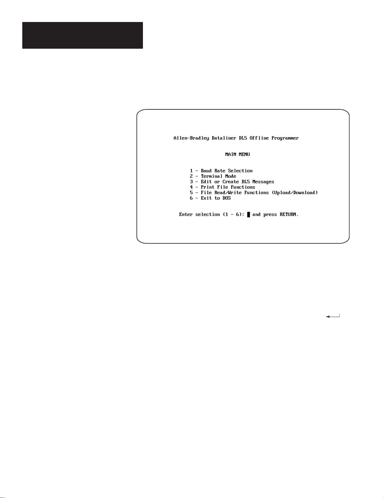
Running DL5 Off-line Programmer
The Main Menu
Access Off-line Programmer functions from the Main Menu. Each function
is described in the following sections.
Option 1 - Baud Rate Selection
Option 2 - Terminal Mode
Option 3 - Edit or Create DL5 Messages
Option 4 - Print File Functions
Option 5 - File Read/Write Functions (Upload/Download)
Option 6 - Exit to DOS
4–2
Page 16

Chapter 4
Running DL5 Off-line Programmer
Option 1 Baud Rate Selection
Use the Baud Rate Selection option from the Main Menu to set the baud rate
of the serial port (COM1) on your computer. The COM1 port will be
connected to the RS-232 serial port on the back of the DL5. (See Chapter 3
for connection instructions.) To enable your computer to communicate with
the DL5, both devices must be set to the same baud rate.
Note: As shipped, the DL5 is initially configured for 9600 baud. COM1
must be set to 9600 baud for the initial communications with the DL5. After
initial hook up, you can use the Off-line Programmer to change the baud rate
to 300 or 1200.
Note: It is recommended that the highest possible baud rate is selected.
Read and write functions may timeout at 300 baud for certain computers.
See the DL5 User Manual for details.
At the prompt you can enter either [1], [2], or [3] or press [END] if you do
not wish to change the baud rate.
• Enter [1] to select 300 baud
• Enter [2] to select 1200 baud
• Enter [3] to select 9600 baud
• Press [END] to set the baud rate and return to the Main Menu
Note: The DL5 displays its baud rate upon power up. To determine if
communication is established between COM1 and the DL5, select Terminal
Mode from the main menu.
4–3
Page 17

Chapter 4
Running DL5 Off-line Programmer
Option 2 T erminal Mode
Use the Terminal Mode Selection option from the Main Menu to make the
computer function as a “dumb” ASCII terminal. This means that you will
use your keyboard to respond to the prompts on the DL5. Refer to your DL5
User’s Manual (Publication 2706-805) for information about on-line
programming from a “dumb” terminal.
While in Terminal Mode, your computer screen will not display the
characters you type. Instead, all characters typed on the keyboard will echo
(display) on the DL5. Your computer screen will continue to display the
Terminal Mode screen until you press [END] to return to the Main Menu.
4–4
When Terminal Mode is selected, the screen displays the baud rate of the
serial port (COM1). Use the Baud Rate Selection option to change the
baud rate.
Press [END] to return to the Main Menu.
ATTENTION: If you delete all messages in the DL5 using the
Terminal Mode, you must wait until the DL5 is done with this
!
step before proceeding. The DL5 will display ”Memory Lost”
while it is still erasing its memory. After this step is complete,
the DL5 will show the RUN? prompt. Then you can continue.
Page 18

Chapter 4
Running DL5 Off-line Programmer
Option 3 Edit or Create DL5 Messages
Select the Edit or Create DL5 Messages option from the Main Menu to
create new messages or edit existing messages. In addition to programming
messages, you can also specify the Special Functions for each DL5 and the
Attributes for each message.
This section shows how to:
Name a DL5 File
Create a New Message
Edit a DL5 File
Edit Existing Messages
Edit Special Functions
Use ”F1” Help Screen
Delete All Files for a DL5 Name
Whether you want to edit an existing message or create a new one, you must
enter a DL5 name. The DL5 name refers to the display that uses a given set
of messages. To select Edit or Create, use the instructions that follow.
4–5
Page 19

Chapter 4
Running DL5 Off-line Programmer
Option 3
Edit or Create
DL5 Messages
Naming a DL5 File
1. After selecting option 3 from the Main Menu, this screen appears:
Before you name a DL5, you can view the lists of names that already exist on
your storage disk.
• Type [CTRL] [G] to show all files for a particular DL5 name.
• Type [CTRL] [L] to show a list of existing DL5 names.
• Type [CTRL] [F] to show a list of all existing message files.
• Press [END] to return to Main Menu.
Use the cursor control keys to scroll through the lists.
2. Enter a DL5 name. DL5 names can be up to 5 DOS allowable characters
in length. All letters and numbers are valid.
If you have chosen an existing DL5 name, go on to Creating a New
Message or Editing the DL5 File. If you have entered a new DL5 name,
continue on in this section.
4–6
Page 20

Chapter 4
Running DL5 Off-line Programmer
3. After entering a new DL5 name the following screen appears:
You will be required to enter information about the DL5 that you have just
named. The program will store this information in a .CNF (configuration)
file. The Off-line Programmer will create a .CNF file for each DL5 Message
Display. The .CNF files are stored differently depending on the type of
computer system as listed below.
• For systems with 1 hard and 1 floppy or micro disk drives, the .CNF files
are stored on the hard disk in the C:\DL5 directory.
• For systems with 2 floppy or micro disk drives, the .CNF files are stored
on the floppy or micro disk in the ”A” drive (or other working drive).
• For systems with 1 floppy or micro disk drive, the .CNF files are stored
on the floppy or micro disk that you have in your machine. Remember to
replace your system disk with a storage disk before saving DL5 names
and messages.
ATTENTION: Deleting the configuration file from DOS will
also delete the counter value that represents the total number of
!
message blocks used in the DL5. See the edit screen on page 14
to see where the ”Total Used” counter data is shown.
4–7
Page 21

Chapter 4
Running DL5 Off-line Programmer
Option 3
Edit or Create
DL5 Messages
4. Enter [1] at the first prompt if you have a one-line display or [2] if it is a
two-line display.
5. Enter [1] at the second prompt if the DL5 has 0.5K memory, [2] if the
memory size is 2K, or [8] if the memory size is 8K.
Make sure the memory size you enter corresponds with the DL5 you are
creating the messages for. The messages may not download if you
specify the wrong memory size.
You may select the default value of [2] by pressing the [RETURN] or
[ENTER] key for both prompts.
6. Press [END] to save the configuration for this DL5 Message Display.
Creating a New Message
You can now create a message for the DL5 that you have named. You will
also be able to define attributes for the message that will control how it is
displayed on the DL5.
4–8
Page 22

Chapter 4
Running DL5 Off-line Programmer
1. Enter a message number to create or edit. If the message number is above
999, you are not allowed to leave the field, but must enter a valid number.
If you select Message #0 by pressing only the [RETURN] or [ENTER]
key, you can edit Special Functions as described in Editing Special
Functions.
2. To find the first unused message number, enter [?] in the message block.
The first open message number will be displayed in the message number
field. Press [ENTER] to edit that message.
3. After entering the Message Number, the list of message attributes appears
on the lower half of the screen as shown below:
Start entering your message text here.
4. Select the attributes for the message. The default values are highlighted
on the screen. Refer to Table 4.A for attribute functions. Some attributes
are mutually exclusive; you can select one but not both. The Off-line
Programmer will not allow you to choose two mutually exclusive
attributes. When an attribute does not apply to your situation, the cursor
automatically advances to the next attribute that you will need to define.
Define the attributes by pressing [Y] or [N] (or a number from 0 to 15 for
Wait Time) and then pressing [RETURN] or the down [] arrow. Use the
up [] arrow to go back up through the list of attributes. You can move
through the list as many times as needed until you press [END].
5. Press [END] to save the attributes for the message.
4–9
Page 23

Chapter 4
Running DL5 Off-line Programmer
Option 3
Edit or Create
DL5 Messages
Table 4.A
DL5 Message Attributes
Attribute Affect on Displayed Messages
The Use Both Lines option will display the message on both lines of the
display as a line mode message. A line mode message will display the first 16
Use Both Lines? ➀
Use Line 1 Only?➀
Use Line 2 Only?➀
Use Least Used
Line? ➀
Scroll Mode?
Wait Time (0-15)?
Auto Clear?➁
Auto Repeat?➁
Flash Message?
➀ These attributes are only applicable to 2 line displays. If you selected a one line display, the
Off-line Programmer automatically prompts you for the attributes applicable for 1 line displays.
➁ These functions are applicable only with message triggers that are either binary or binary coded
decimal (BCD) format. They are not applicable when the DL5 is in the round robin or priority
mode.
characters of the message on the first line of the display and the next 16
characters on the second line of the display. For longer messages, the DL5 will
display the first 2 lines for the specified Wait Time, and then repeat this process
for the remaining blocks of the message.
The Use Line 1 option will display the message only on the first line of the
display. Any messages present on the second line will remain intact.
The Use Line 2 option will display the message only on the second line of the
display. Any messages present on the first line of the display will remain intact.
The Use Least option will display the message on the least recently used line.
Any messages present on the other line of the display will remain intact.
The Scroll Mode option toggles between the scroll mode and line mode. In
scroll mode the message scrolls across the display one character at a time from
right to left. In line mode one message block (16 characters) is displayed at a
time. If a message is longer than one block, the DL5 will display a message
block for the specified Wait Time and then display the next block of the
message.
Note: If you are using a two line DL5 and selected the Both Lines option, the
line mode will be selected automatically. The Scroll Mode option becomes
unavailable for selection after Both Lines has been chosen.
Wait Time controls how long a message or a portion of a message is displayed.
You must enter a value between 0 and 15. The unit of time being selected
depends upon whether line or scroll mode was chosen. If Scroll Mode was
chosen, the wait time is the amount of time that elapses, in tenths of a second,
before the next character is scrolled on the display. If the Line Mode was
chosen, the wait time is the amount of time, in seconds, that a message block
is displayed.
If you select the Auto Clear option, the DL5 will clear the display after the
message has been displayed for the requested wait time. If you do not select
the Auto Clear option, the last block of the message will remain on the display
until it is replaced with another message.
This attribute is used with scrolling messages or line mode messages longer
than one screen in length. If you select the Auto Repeat option, the message
continually re-triggers itself once the programmed Wait Time has expired. If
you do not select the Auto Repeat option, the DL5 will display the message
only once.
The Flash Message option will cause the message to flash once per second
while it is being displayed.
4–10
Page 24

Chapter 4
Running DL5 Off-line Programmer
6. After you have specified the attributes for the message, you can now enter
the actual message. The DL5 stores messages in blocks of 16 characters.
A message can be more than one block in length. You can view up to 16
message blocks on the Off-line Programmer’s Message Editing screen.
Enter the text of your message. Press [F1] for help on moving the cursor
and editing message blocks. The help screen is shown in the “F1” Help
Screen section.
7. Press [END] to save the message. The program will create a .DL5 file for
each message that you save. The individual message file names consist of
the DL5 name, message number, and the extension .DL5.
For example: The message file name shown in the screen on Page 9 was
NEW100.DL5. ’NEW’ is the name of the DL5 display, ’100’ is the message
number, and ’.DL5’ indicates that this is a message (not configuration) file.
See Naming a DL5 File for information on .CNF files. The .DL5 files are
stored differently depending on the type of computer system as listed below.
• For systems with 1 hard and 1 floppy or micro disk drive, the .DL5 files
are stored on the hard disk in the C:\DL5 directory.
• For systems with 2 floppy or micro disk drives, the .DL5 files are stored
on the floppy or micro disk in the ”A” drive (or other working drive).
• For systems with 1 floppy or micro disk drive, the .DL5 files are stored
on the floppy or micro disk that you have in your machine. Remember to
replace your system disk with a storage disk before saving DL5 names
and messages.
4–11
Page 25

Chapter 4
Running DL5 Off-line Programmer
Option 3
Edit or Create
DL5 Messages
Editing a DL5 File
This section is divided into 4 parts:
• Editing Special Functions
• Editing Existing Messages
• “F1” Help Screen
• Deleting All Files for a DL5 Name
After you enter an existing DL5 name, the Off-line Programmer will prompt
you for a message number. There are 3 types of message numbers you can
choose at this point:
• A new message number. See Creating a New Message.
• Special Functions Message # 0. See Editing Special Functions.
• An existing message number. See Editing Existing Messages.
Editing Special Functions
When you enter message #0, the Special Function selections will be
displayed as shown. The Special Function settings control how the DL5 will
operate in the Run Mode. This step must be completed before the Off-line
Programmer will allow you to download messages.
4–12
Page 26

Chapter 4
Running DL5 Off-line Programmer
There are four Special Functions. See Table 3.B for Functions and Options.
Table 4.B
Display Special Functions
Special Function Option Description
High True
Parallel Port Logic
DL5 RS-232 Port
Baud Rate
DL5 Run Mode
Autorun Message
Number
Y
N
3
1
9
NM
PR
BN
BC
RR
A Valid Message
Number
Voltages on data lines are positive logic signals.
Voltages on data lines are negative logic signals.
DL5 Baud Rate set to 300
DL5 Baud Rate set to 1200
DL5 Baud Rate set to 9600
Parallel port uses NUMERIC run mode
Parallel port uses PRIORITY run mode
Parallel port uses BINARY run mode
Parallel port uses BINARY CODED DECIMAL (BCD) run
mode
Parallel port uses ROUND ROBIN run mode
This message will be displayed when the DL5 goes into
Autorun Mode after power has been applied Note:
Select 0 to disable the Autorun function.
1. Define the Special Functions settings by selecting the desired option code
and then pressing [RETURN] or [ENTER]. You can move about within
the menu by using the [RETURN] key or the up [] and down [] arrow
keys.
2. Press [END] to save the Special Functions and return to the Edit screen.
4–13
Page 27

Chapter 4
Running DL5 Off-line Programmer
Option 3
Edit or Create
DL5 Messages
Editing Existing Messages
When you edit an existing message, you may change either the text or the
attributes of the message. The edit screen is shown below.
1. Press [CTRL] [A] to edit attributes.
2. Use the [RETURN] key or the up [] and down [] arrow keys to move
the cursor through the list of attributes.
3. Press [END] to save the attributes.
4. Edit the message text. Press [F1] to see the Help Screen of edit
commands or see the ”F1” Help Screen section on the next page.
Note: If you decide that you prefer the old version of your message,
press [ESC] to abort. Your message will remain unchanged.
5. Press [END] or [CTRL] [Q] to save your changes. The new version of
the message is now stored in the .DL5 message file.
4–14
Page 28

Chapter 4
Running DL5 Off-line Programmer
”F1” Help Screen
The “F1” Help screen shows the list of edit commands that you can use to
edit messages. The Help screen can only be accessed while you are editing a
message. To see the Help screen press [F1]. The editing functions listed on
the “F1” Help screen are shown in the table below:
Press: To:
[CTRL] A Edit message attributes.
[CTRL] C Center text in block.
[CTRL] D or
[DEL] key
[CTRL] E Erase complete message.
[CTRL] H,
[BACKSPACE],
or z
[CTRL] I, [INS] key Insert Block after current position.
[CTRL] J, [TAB],
[PG DN], or #
[CTRL] K, [SHIFT]
[TAB], [PG UP],
or "
[CTRL] L, or ! Move cursor one character to the right.
[CTRL] V, or
[CTRL] X
[HOME] key Move cursor to first message block.
[ESC] key Quit and do not save message or changes
[END] key, or
[CTRL] Q
Delete Current Block.
Move cursor one character to the left.
Move cursor one block forward (right).
Move cursor one block backwards (left).
Insert a variable in the message.
Quit and Save message.
Press any key to exit the Help screen and continue editing the message.
Deleting all Files for a DL5 Name
Use the following procedure to delete all files for a specific DL5 name.
These files can be deleted in DOS. Exit to DOS with Option 6 of the Main
Menu.
At the DOS prompt: A:\DL5> type the following command:
DEL FILE NAME*.* [ENTER]
Example: If you wish to delete the files for the DL5 named NEW, you
would type the following at the DOS prompt: A:\DL5>:
DEL NEW*.* [ENTER]
All files for the DL5 named NEW would now be deleted.
4–15
Page 29

Chapter 4
Running DL5 Off-line Programmer
Option 4 Print File Functions
Select option 4 - Print File Functions to print:
• DL5 Messages
• Message Attributes
• Special Function Settings
For this option, you must have a printer connected to the computer LPT1
parallel port.
NOTE: Most printers are designed to hook up to the parallel port, but if
your printer uses the serial input, you can redirect the printer output to a
serial port such as COM2. You can do this before running the DL5 program
at the DOS prompt by typing the following commands:
MODE LPT1: =COM2
MODE COM2: 9600,N,8,1
These commands configure COM2 for a serial printer with 9600 baud, no
parity, 8 data bits, and 1 stop bit.
Note that these commands will require customization for your particular
computer and/or printer. Consult your computer user’s manual for the exact
commands required.
4–16
1. Enter the DL5 name to access the DL5 Messages that you would like to
print.
2. Select the range of message numbers that you want to print. If you select
or include Message #0, the Special Functions settings will be printed.
Page 30

Chapter 4
Running DL5 Off-line Programmer
3. Answer [Y] or [N] if you want the message attributes printed. If you
select [Y], they are printed for every message in the range you selected in
Step 2.
You may use the cursor control keys to change a message number before
the last [ENTER] is pressed to begin printing.
4. Press [ENTER] to start printing after indicating whether or not to print the
message attributes.
5. Press [ESC] to abort and return to the Main Menu.
Option 5 File Read/Write Functions
Select File Read/Write Functions from the Main Menu to transfer messages
between your computer and the DL5 Message Display.
You have the following choices:
• Enter [1] to read an entire DL5 memory to a disk
• Enter [2] to write from disk to DL5 memory
• Press [END] to return to the Main Menu
4–17
Page 31

Chapter 4
Running DL5 Off-line Programmer
Option 5
File Read/Write Functions
Read from DL5 Memory to Disk
Reading from DL5 memory is similar to naming a DL5. You must supply
configuration information so that the Off-line Programmer can store the
messages correctly. After you have selected the read function, the following
screen will appear:
Before uploading messages from a DL5, you can view the lists of names that
already exist on your storage disk.
• Press [CTRL] [L] to view existing DL5 names.
• Type [CTRL] [F] to view existing DL5 message files.
Type in the DL5 name and press [RETURN] to begin uploading messages.
Press [ESC] to abort the reading and return to the Main Menu if needed.
After the first message is uploaded, the following screen will appear:
4–18
Page 32

Chapter 4
Running DL5 Off-line Programmer
1. Enter [1] at the first prompt if you are reading from a one-line display or
[2] if it is a two-line display.
2. Enter [1] at the second prompt if the DL5 has 0.5K memory, [2] if the
memory size is 2K, or [8] if the memory size is 8K.
You may select the default value of 2 by pressing the [RETURN] or
[ENTER] key for both prompts.
3. Press [END] to save the configuration for this DL5 Message Display.
Note: If you do not reply to the prompts on this screen, the upload will be
aborted.
Note: If you receive a communications error, check that your cable is
securely connected to both the computer and DL5 and that the baud rate of
COM1 matches the baud rate of the DL5. Also, using 300 baud rate may
cause read functions to abort. It is recommended that a higher baud rate be
used. Use Main Menu Option 1 - Baud Rate Selection to change the baud
rate of the computer and Option 2 Terminal Mode to change the baud rate of
the DL5.
Write from a Disk to DL5 Memory
When you enter 2 on the Read/Write Functions screen the following screen
will appear. If you would like to see a list of DL5 names on your storage
disk, press [CTRL] [L]. Otherwise, type in the DL5 name and press
[ENTER]. Press [ESC] to return to the Main Menu if necessary.
4–19
Page 33

Chapter 4
Running DL5 Off-line Programmer
Option 5
File Read/Write Functions
After typing the DL5 name and pressing [ENTER] the following
screen appears:
4–20
ATTENTION: DO NOT begin downloading messages while the
DL5 is displaying ”Memory Lost”. This warning message will
!
appear after the messages have been deleted (from the terminal
mode) until the DL5 has completed the erasing operation.
Note the warning message. Make sure that the selected messages are
compatible with the DL5 connected to the computer:
1. Do not download messages that are created for a two-line display, to a
one-line display and vice versa.
2. Do not download messages created for a DL5 which has more memory
than the DL5 receiving the messages. For example; don’t download
messages created for a DL5 with 2K memory (94 message blocks) to a
DL5 with 0.5K of memory (21 message blocks). All of the messages may
not fit.
If you want to clear memory in the DL5 and download all of the messages
for the DL5 name, simply press [ENTER] at this point. The software will
automatically clear memory in the DL5 and download all messages.
If Message #0 (DL5 input port and Special Function settings) does not exist,
the software will not download the messages. Create Message #0 with
Option 3, Edit or Create DL5 Messages. Then simply answer the questions.
See the DL5 User Manual for more details on these settings.
Page 34

Chapter 4
Running DL5 Off-line Programmer
Download a range of messages only to a DL5 Memory.
If (to save time) you only need to download a message or two because of
some additions or modifications to that message, press [N] and [ENTER] to
answer no to the download all messages question and this will bring up the
following screen.
Option 6 Exit to DOS
Enter the first and last message in a range to download just those messages.
This method does not “clear memory” before downloading, therefore:
1. Messages added to existing messages in the DL5 may exceed the DL5
memory capacity. Do not use this method of downloading messages if
you do not know what messages are already in the DL5 memory.
2. Do not delete a message on the computer and then download a range
including that message number to the DL5. The software erases each
message in the DL5 individually prior to downloading that message. If
there is no new message to download, the existing message in the DL5
will be left unchanged.
Select Option 6 from the Main Menu to return to DOS.
4–21
Page 35

Rockwell Automation helps its customers receive a superior return on their investment by bringing
together leading brands in industrial automation, creating a broad spectrum of easy-to-integrate
products. These are supported by local technical resources available worldwide, a global network
of system solutions providers, and the advanced technology resources of Rockwell.
Worldwide representation.
Argentina • Australia • Austria • Bahrain • Belgium • Bolivia • Brazil • Bulgaria • Canada • Chile • China, People’s Republic of • Colombia • Costa Rica • Croatia • Cyprus
Czech Republic • Denmark • Dominican Republic • Ecuador • Egypt • El Salvador • Finland • France • Germany • Ghana • Greece • Guatemala • Honduras • Hong Kong
Hungary • Iceland • India • Indonesia • Iran • Ireland •Israel • Italy • Jamaica • Japan • Jordan • Korea • Kuwait • Lebanon • Macau • Malaysia • Malta • Mexico •Morocco
The Netherlands •New Zealand • Nigeria • Norway • Oman • Pakistan • Panama • Peru • Philippines • Poland • Portugal • Puerto Rico • Qatar • Romania • Russia • Saudi
Arabia • Singapore • Slovakia • Slovenia • South Africa, Republic of • Spain • Sweden •Switzerland • Taiwan • Thailand • Trinidad • Tunisia • T urkey • United Arab Emirates
United Kingdom • United States • Uruguay • Venezuela
Rockwell Automation Headquarters, 1201 South Second Street, Milwaukee, WI 53204-2496 USA, T el: (1) 414 382-2000 Fax: (1) 414 38 2-4444
Rockwell Automation European Headquarters, Avenue Hermann Debroux, 46, 1160 Brussels, Belgium, Tel: (32) 2 663 06 00, Fax: (32) 2 663 06 40
Rockwell Automation Asia Pacific Headquarters, 27/F Citicorp Centre, 18 Whitfield Road, Causeway Bay, Hong Kong, Tel: (852) 2887 4788, Fax: (852) 2508 1846
World Wide Web: http://www.ab.com
Publication 2706-806 – October 1992
Supersedes Publication 2706-806 – Dated January 1990
Copyright 1992 Allen-Bradley Company, Inc. Printed in USA
40061-089-02(A)
 Loading...