

Page 1

Allen-Bradley
Dataliner DL20
Series Offline
User
Programming
Software
(Cat. No. 2706–NP3)
Manual
Page 2
Important User Information
Because of the variety of uses for the products described in this
publication, those responsible for the application and use of this
control equipment must satisfy themselves that all necessary steps
have been taken to assure that each application and use meets all
performance and safety requirements, including any applicable laws,
regulations, codes and standards.
The illustrations, charts, sample programs and layout examples
shown in this guide are intended solely for purposes of example.
Since there are many variables and requirements associated with any
particular installation, Allen-Bradley does not assume responsibility
or liability (to include intellectual property liability) for actual use
based upon the examples shown in this publication.
Allen-Bradley publication SGI-1.1, Safety Guidelines for the
Application, Installation, and Maintenance of Solid-State Control
(available from your local Allen-Bradley office), describes some
important differences between solid-state equipment and
electromechanical devices that should be taken into consideration
when applying products such as those described in this publication.
Reproduction of the contents of this copyrighted publication, in
whole or in part, without written permission of Allen-Bradley
Company, Inc., is prohibited.
Throughout this manual we use notes to make you aware of safety
considerations:
ATTENTION: Identifies information about practices
or circumstances that can lead to personal injury or
!
Attention statements help you to:
death, property damage or economic loss.
• identify a hazard
• avoid the hazard
• recognize the consequences
Important: Identifies information that is critical for successful
application and understanding of the product.
Page 3

Table of Contents
DL20 Offline Programming Software
User Manual
Using this Manual
What You Need
Installing the Software
Chapter 1
Chapter Objectives 1–1. . . . . . . . . . . . . . . . . . . . . . . . . . . . . . . . . . . . . . . . .
What You Need to Know 1–1. . . . . . . . . . . . . . . . . . . . . . . . . . . . . . . . . . . .
Contents of Manual 1–1. . . . . . . . . . . . . . . . . . . . . . . . . . . . . . . . . . . . . . . .
Conventions 1–2. . . . . . . . . . . . . . . . . . . . . . . . . . . . . . . . . . . . . . . . . . . . . .
Related Publications 1–2. . . . . . . . . . . . . . . . . . . . . . . . . . . . . . . . . . . . . . . .
Chapter 2
Chapter Objectives 2–1. . . . . . . . . . . . . . . . . . . . . . . . . . . . . . . . . . . . . . . . .
Personal Computer Requirements 2–1. . . . . . . . . . . . . . . . . . . . . . . . . . . . .
DL20 Programming Software 2–1. . . . . . . . . . . . . . . . . . . . . . . . . . . . . . . .
DL20 Dataliner Message Display 2–2. . . . . . . . . . . . . . . . . . . . . . . . . . . . .
Data Recorder 2–2. . . . . . . . . . . . . . . . . . . . . . . . . . . . . . . . . . . . . . . . . . . . .
Download Cables 2–2. . . . . . . . . . . . . . . . . . . . . . . . . . . . . . . . . . . . . . . . . .
Chapter 3
Chapter Objectives 3–1. . . . . . . . . . . . . . . . . . . . . . . . . . . . . . . . . . . . . . . . .
Checking Available RAM 3–1. . . . . . . . . . . . . . . . . . . . . . . . . . . . . . . . . . .
Making a Copy of the Software 3–1. . . . . . . . . . . . . . . . . . . . . . . . . . . . . . .
Installing the DL20 Programming Software 3–1. . . . . . . . . . . . . . . . . . . . .
Computer with 1 Hard and 1 Floppy or Micro Disk Drive 3–2. . . . . . . .
Computer with 2 Floppy or Micro Disk Drives 3–3. . . . . . . . . . . . . . . . .
Computer with 1 Floppy or Micro Disk Drive 3–4. . . . . . . . . . . . . . . . . .
Initial Startup 3–5. . . . . . . . . . . . . . . . . . . . . . . . . . . . . . . . . . . . . . . . . . . . .
Exiting the DL20 Software 3–6. . . . . . . . . . . . . . . . . . . . . . . . . . . . . . . . . .
Function Keys 3–6. . . . . . . . . . . . . . . . . . . . . . . . . . . . . . . . . . . . . . . . . . . . .
DL20 Files 3–6. . . . . . . . . . . . . . . . . . . . . . . . . . . . . . . . . . . . . . . . . . . . . . .
Configuration Functions
Message Operations
Chapter 4
Chapter Objectives 4–1. . . . . . . . . . . . . . . . . . . . . . . . . . . . . . . . . . . . . . . . .
What are the Configuration Functions 4–1. . . . . . . . . . . . . . . . . . . . . . . . . .
Configuring the Computer Serial Port 4–2. . . . . . . . . . . . . . . . . . . . . . . . . .
Configuring the DL20 Serial Port 4–3. . . . . . . . . . . . . . . . . . . . . . . . . . . . .
Configuring the DL20 Parallel Port 4–5. . . . . . . . . . . . . . . . . . . . . . . . . . . .
Configuring Special Functions of DL20 4–7. . . . . . . . . . . . . . . . . . . . . . . .
Chapter 5
Chapter Objectives 5–1. . . . . . . . . . . . . . . . . . . . . . . . . . . . . . . . . . . . . . . . .
How Messages are Stored 5–1. . . . . . . . . . . . . . . . . . . . . . . . . . . . . . . . . . .
Creating New Messages 5–2. . . . . . . . . . . . . . . . . . . . . . . . . . . . . . . . . . . . .
Entering Message Text 5–6. . . . . . . . . . . . . . . . . . . . . . . . . . . . . . . . . . . .
Editing Messages 5–8. . . . . . . . . . . . . . . . . . . . . . . . . . . . . . . . . . . . . . . . . .
Deleting Messages 5–10. . . . . . . . . . . . . . . . . . . . . . . . . . . . . . . . . . . . . . . . .
Copying Messages 5–11. . . . . . . . . . . . . . . . . . . . . . . . . . . . . . . . . . . . . . . . .
i
Page 4

Table of Contents
DL20 Offline Programming Software
User Manual
Message File Conversions
Transferring S Record Files
Downloading Message Files
Chapter 6
Chapter Objectives 6–1. . . . . . . . . . . . . . . . . . . . . . . . . . . . . . . . . . . . . . . . .
Overview of Conversion Functions 6–1. . . . . . . . . . . . . . . . . . . . . . . . . . . .
Converting Message Files to S Record File 6–2. . . . . . . . . . . . . . . . . . . . . .
Converting S Record File to Message Files 6–4. . . . . . . . . . . . . . . . . . . . . .
Viewing DL20 Files 6–5. . . . . . . . . . . . . . . . . . . . . . . . . . . . . . . . . . . . . . . .
Chapter 7
Chapter Objectives 7–1. . . . . . . . . . . . . . . . . . . . . . . . . . . . . . . . . . . . . . . . .
Accessing File Read/Write Functions 7–1. . . . . . . . . . . . . . . . . . . . . . . . . .
Connecting Equipment 7–2. . . . . . . . . . . . . . . . . . . . . . . . . . . . . . . . . . . . . .
Connecting Personal Computer to DL20 7–2. . . . . . . . . . . . . . . . . . . . . .
Connecting Personal Computer to Data Recorder 7–3. . . . . . . . . . . . . . .
Downloading S Record File to DL20 7–4. . . . . . . . . . . . . . . . . . . . . . . . . .
Uploading DL20 Memory to Personal Computer 7–6. . . . . . . . . . . . . . . . .
Downloading S Record File to Data Recorder 7–8. . . . . . . . . . . . . . . . . . . .
Uploading File from Data Recorder 7–10. . . . . . . . . . . . . . . . . . . . . . . . . . . .
Viewing DL20 Files 7–12. . . . . . . . . . . . . . . . . . . . . . . . . . . . . . . . . . . . . . . .
Helpful Hints 7–14. . . . . . . . . . . . . . . . . . . . . . . . . . . . . . . . . . . . . . . . . . . . .
Chapter 8
Chapter Objectives 8–1. . . . . . . . . . . . . . . . . . . . . . . . . . . . . . . . . . . . . . . . .
Connecting to DL20 8–1. . . . . . . . . . . . . . . . . . . . . . . . . . . . . . . . . . . . . . . .
Downloading Message Files 8–2. . . . . . . . . . . . . . . . . . . . . . . . . . . . . . . . .
Verifying Message Download 8–5. . . . . . . . . . . . . . . . . . . . . . . . . . . . . . . .
Helpful Hints 8–5. . . . . . . . . . . . . . . . . . . . . . . . . . . . . . . . . . . . . . . . . . . . .
Using Terminal Mode
Printing Messages
ii
Chapter 9
Chapter Objectives 9–1. . . . . . . . . . . . . . . . . . . . . . . . . . . . . . . . . . . . . . . . .
Connecting to DL20 9–1. . . . . . . . . . . . . . . . . . . . . . . . . . . . . . . . . . . . . . . .
Entering Terminal Mode 9–2. . . . . . . . . . . . . . . . . . . . . . . . . . . . . . . . . . . .
Chapter 10
Chapter Objectives 10–1. . . . . . . . . . . . . . . . . . . . . . . . . . . . . . . . . . . . . . . . .
Connecting Printer 10–1. . . . . . . . . . . . . . . . . . . . . . . . . . . . . . . . . . . . . . . . .
Printing Messages 10–2. . . . . . . . . . . . . . . . . . . . . . . . . . . . . . . . . . . . . . . . . .
Page 5

Table of Contents
A.1A.2A.3A.4A.5A.
.A
DL20 Offline Programming Software
User Manual
Connection Diagrams
6
5
Appendix A
Figures
Connecting DL20 to an XT (25-Pin) Compatible Computer A–1. . . . . . . . .
Connecting DL20 to an AT (9-Pin) Compatible Computer A–1. . . . . . . . . .
25-to-9 Pin Adapter Cable (Null Modem) A–1. . . . . . . . . . . . . . . . . . . . . . .
Connecting 1770-SA or -SB Data Recorder to IBM XT Serial Port A–2. . .
Connecting 1770-SA or -SB Data Recorder to IBM AT Serial Port A–2. . .
Connecting 1770-SA or -SB Data Recorder to 6120 Serial Port A–2. . . . . .
Tables
Message Attributes 5–5. . . . . . . . . . . . . . . . . . . . . . . . . . . . . . . . . . . . . . . . .
iii
Page 6
Chapter
hat You Need to Kno
Chapter Objectives
W
w
A–B
1
Using this Manual
This chapter gives an overview of the manual, including:
• What you need to know
• Contents of manual
• Manual conventions
• Related publications
No special knowledge is required to read this manual or use the DL20
Offline Programming Software (Catalog No. 2706-NP3). However, you
should be familiar with DL20 operations and how it will be integrated
into your control system.
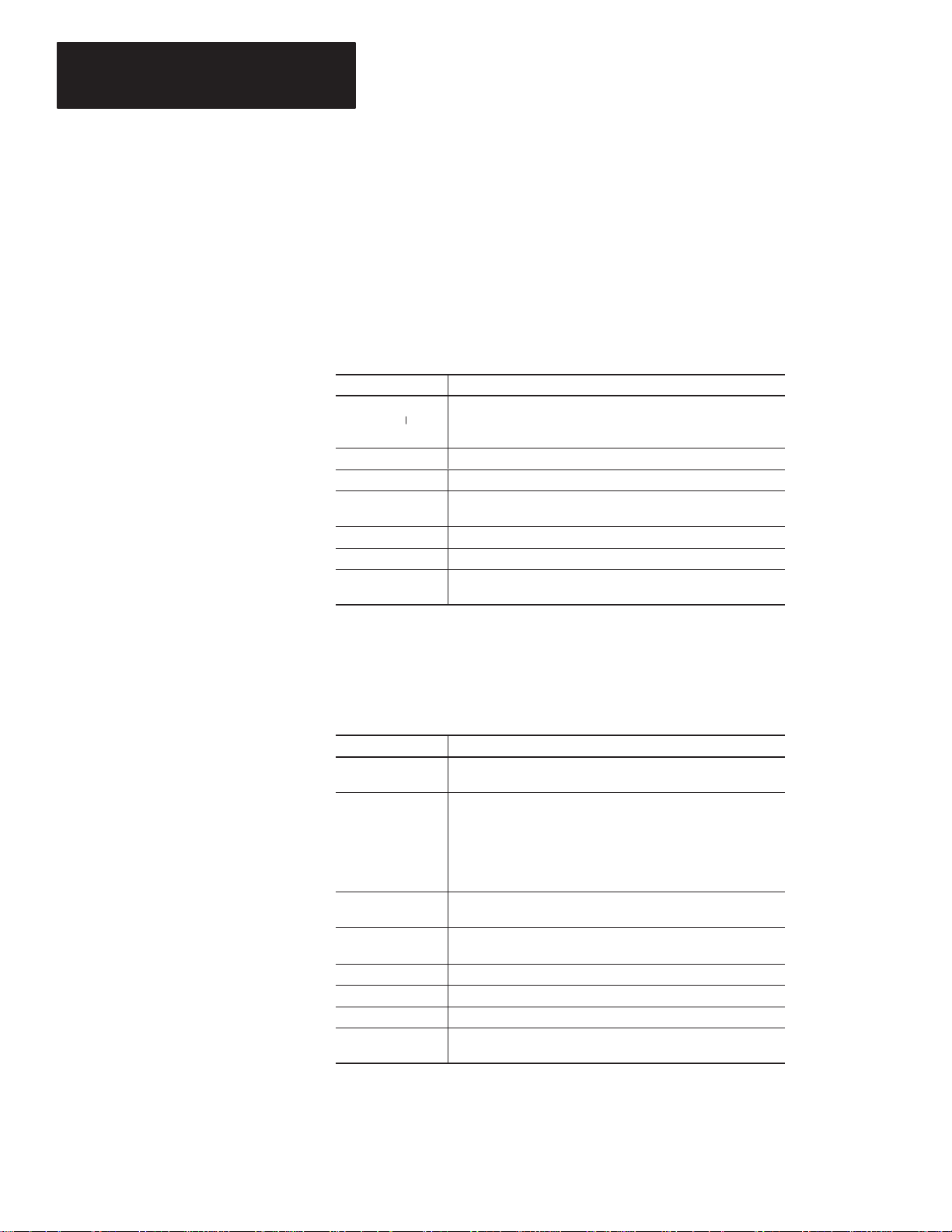
Contents of Manual
This manual describes how to use the DL20 Offline Programming
Software to configure and create message files for the DL20 Dataliner
Message Displays. The manual is organized as follows:
Chapter Title Purpose
1 Using this Manual Provides an overview of the manual.
Lists equipment needed to use the software and
2 What You Need
3 Installing the Software
4 Configuration Functions
5 Message Operations
6 Message File Conversions
7 Transferring S Record Files
8
9 Using Terminal Mode
10 Printing Messages Describes how to print DL20 messages files.
Downloading
Messages Files
to transfer DL20 files between your computer and
the DL20 or data recorder.
Tells how to install the DL20 Offline Programming
Software on your computer.
Shows how to configure the serial port of your
computer, the serial and parallel port of the DL20,
and special functions of the DL20.
Shows how to create, edit, copy and delete DL20
messages.
Tells how to convert DL20 message files to and
from S Record files for downloading and storage.
Tells how to transfer S Record Files between your
computer and a DL20 or data recorder.
Tells how to download DL20 message files from
your computer to a DL20.
Explains how your computer can communi- cate
with a DL20 in terminal/keyboard mode.
1–1
Page 7

Chapter 1
elate
ations
Using This Manual
Conventions
R
d Public
The following conventions are used throughout this manual:
• Keys you press on your computer keyboard are enclosed in brackets [ ].
For example: [Esc] refers to the Escape key.
• [Enter] refers to the carriage return key on your computer keyboard.
This key may appear on your keyboard as [Return] or [←].
• References to DL20 menu options and screens are italicized.
• Text you type at your keyboard appears in bold letters.
For example: Type 1 and [Enter].
Other publications you may want to refer to include:
• Publication No. 2706-801
User Manual for Series A - F DL20 Dataliner Message Displays
• Publication No. 2706-814
User Manual for Series G DL20 Dataliner Message Displays
• Publication No. 1770-6.5.4
User Manual for Data Cartridge Recorder
1–2
Page 8
Chapter
rogramming Software
Chapter Objectives
Personal Computer Requirements
Personal Computer
A–B
2
What You Need
This chapter describes the items needed to run the DL20 Offline
Programming Software including:
• Personal Computer Requirements
• DL20 Programming Software
• DL20 Dataliner Message Display
• Data Recorder
• Download Cable
The DL20 Programming Software runs on the following computers:
• IBM PC/XT/AT or 100% compatible
Allen-Bradley T45 and T50 Industrial Computers
Allen-Bradley 6120, 6121 and 6122 Industrial Computers
• One or two floppy drives (720K minimum)
• Hard drive is recommended and required on computers with only 1
floppy drive
• 448K of RAM
• DOS 3.0 or later
• Serial port on Com1 or Com 2
• Printer port to print messages
• Monochrome or color monitor
DL20 P
DL20 Software
The DL20 Offline Programming Software is an optional package used to
create messages for the DL20 Dataliner Message Displays. You need version
4.2 or higher. The software is provided on 5 1/
and 3 1/
4
inch diskettes.
2
2–1
Page 9
Chapter 2
ription
What Y ou Need
DL20 Dataliner Message Display
Data Recorder
Download Cables
The DL20 Offline Programming Software creates configuration and message
files for the following DL20 Dataliner Message Displays:
Desc
One Line Display 2706-B13J8 2706-B13J16 2706-B13J31
Two Line Display 2706-B23J8 2706-B23J16 2706-B23J31
Four Line Display – 2706-B43J16 2706-B43J31
8K Memory 16K Memory 31K Memory
Catalog No. Catalog No. Catalog No.
DL20 messages can be downloaded from your computer to a DL20 Dataliner
or to one of the following Allen-Bradley Data Recorders:
• Catalog Number 1770-SA Data Recorder
• Catalog Number 1770-SB Data Recorder
To transfer messages between your computer and a DL20 or data recorder, or
to communicate with a DL20 using terminal mode you need to use the
appropriate cable. The table below lists the available cables.
Catalog No. Description
2706-NC2 Connects the DL20 to an Allen-Bradley 6120, 1784-T45, IBM
PC/XT or compatible computer with a 25-pin male connector on
the serial port.
Cable has spade lug connections for the RS-232 port of the DL20
and a 25-pin female D Connector for the computer’s serial port.
2706-NC2 plus a
9-to-25 pin AT Adapter Cable➀
2706-NC1 Connects the DL20 to an IBM compatible computer with a 25-pin
1784-CYS Connects the 1770-SA or -SB Data Recorder to the serial port of
1784-CAS Connects the 1770-SA or -SB Data Recorder to an IBM AT 9-pin
1784-CXS Connects the 1770-SA or -SB Data Recorder to the serial port of
➀ The 9-to-25 pin Adapter Cable is available at computer stores (must be Null Modem Cable).
Connects the DL20 to an Allen-Bradley 6121, 1784-T50, IBM
PC/AT or compatible computer. The serial ports of these computers use a 9-pin male connector.
Cable has spade lug connections for the RS-232 port of the DL20
and a 25-pin female D Connector. The AT Adapter Cable connects the 2706-NC2 cable to the 9-pin serial port of the computer.
female connector on the serial port. Typically, parallel ports and
display ports have female connectors.
Cable has spade lug connections for the RS-232 port of the DL20
and a 25-pin male D Connector for the computer’s serial port
(with pins 18 & 25 jumpered together).
an Allen-Bradley 6120 computer.
serial port.
an IBM XT or Allen-Bradley 1784-T50 terminal.
Appendix A provides connection diagrams for the above cables if you want
to make your own cables.
2–2
Page 10

Chapter
Installing the
Chapter Objectives
Checking Available RAM
Making a Copy of the Software
A–B
3
Installing the Software
This chapter shows how to install the DL20 Offine Programming Software
on your computer.
You should have at least 448K of available RAM to run the DL20 Offline
Programming Software on your computer. Check the available RAM on
your computer using the DOS CHKDSK command.
As a safety precaution, it is recommended that you make at least one copy
of the DL20 Offline Programming Software and save the original disk as
a master.
DL20
Programming Software
1
The 5
with a write protect tab. You cannot write to the disk unless the write protect
tab is removed. However, you can make copies without removing the tab.
This section shows how to install the DL20 Programming Software on:
• Computer with 1 Hard drive and 1 Floppy or Micro disk drive
• Computer with 2 Floppy or Micro disk drives
• Computer with 1 Floppy or Micro disk drive
Refer to the appropriate section.
The software is provided on 5
appropriate for your computer.
/
and 3 1/
4
inch installation disks are shipped from Allen-Bradley
2
1
/
and 3 1/
4
inch disks. Use the size
2
3–1
Page 11

Chapter 3
Installing the
Installing the Software
DL20
Programming Software
Computer with 1 Hard and 1 Floppy or Micro Disk Drive
This section shows how to install the DL20 Offline Programming Software
on a personal computer with 1 hard drive and 1 floppy or micro disk drive.
The installation procedure creates a DL20 subdirectory for storing the
programming software (DL20.EXE) and all other DL20 files created with
the software.
The prompts and responses you see below will be identical or similar to what
you see on your computer display.
1. Turn on your computer. Your computer will display the currently active
drive: A, B or C. For example:
C:>
2. Create a DL20 subdirectory on your hard drive using the MD command.
C:> MD \DL20 [Enter]
C:>
3. Move to the new DL20 subdirectory using the CD command.
C:> CD \DL20 [Enter]
C:\DL20>
4. Insert the appropriate installation disk for the DL20 Offline Programming
Software into the floppy drive.
5. Type the following command line to copy the DL20 Programming
Software into the DL20 subdirectory.
C:\DL20> COPY A:DL20.EXE [Enter]
1 file(s) copied
The DL20 Programming Software is now installed on your hard drive.
6. Remove the installation disk from the floppy drive and store it in a
safe place.
See page 3–5 for details on initial startup.
3–2
Page 12
Chapter 3
Installing the Software
Computer with 2 Floppy or Micro Disk Drives
This section shows how to install the DL20 Offline Programming Software
on a personal computer with 2 (720K) floppy or micro disk drives.
The installation procedure creates a System/DL20 disk which lets you run
the software and store messages in a DL20 subdirectory. You can create a
separate formatted disk for storing DL20 files in an S Record file format.
The prompts and responses you see below will be identical or similar to what
you see on your computer display.
ATTENTION: Before beginning the procedure, write protect
your DOS disk using a write protect tab. See your computer’s
!
DOS manual.
The steps below create a single System/DL20 disk that you can use to boot
your computer and run the DL20 software.
1. Insert your computer’s DOS write protected disk into drive A and turn on
the computer. Enter date and time if applicable.
2. Insert a blank disk into drive B.
3. Format and create a system disk using the following command:
A:> Format B:/S [Enter]
When the disk is formatted, this prompt appears. Type N and [Enter].
B:> Format Another (Y/N)? N [Enter]
4. Remove the DOS disk from drive A and store in a safe place.
5. Insert the DL20 installation disk into drive A and type:
A:> COPY DL20.EXE B: [Enter]
1 file(s) copied
The DL20 Programming Software is now installed on the disk in drive B.
6. Remove the DL20 installation disk from drive A and store in a
safe place.
7. Move the System/DL20 disk from drive B to drive A.
8. Create a DL20 subdirectory on the System/DL20 disk by entering:
A:> MD \DL20 [Enter]
Operating in a subdirectory allows you to create approximately 100
DL20 messages.
3–3
Page 13
Chapter 3
Installing the
Installing the Software
DL20
Programming Software
Computer with 2 Floppy or Micro Disk Drives (continued)
9. Create an AUTOEXEC.BAT file on the System/DL20 disk by typing:
A:> COPY CON AUTOEXEC.BAT [Enter]
PROMPT P$G$ [Enter]
CD\DL20 [Enter]
A:\DL20 [Enter]
[Ctrl][Z] [Enter]
10. When the file is copied, turn your computer off and on with the
System/DL20 disk in drive A. The DL20 Offline Programming Software
will automatically begin.
See page 3–5 for details on initial startup.
Computer with 1 Floppy or Micro Disk Drive
This section shows how to run the DL20 Offline Programming Software on a
computer with only 1 floppy or micro disk drive. We recommend that you
create a separate disk for storing separate S Record files for each DL20
Dataliner you program.
Important: Storing files on the DL20 Offline Programmer disk restricts
the number of files you can create.
The prompts and responses you see below will be identical or similar to what
you see on your computer display.
ATTENTION: Before beginning the procedure, write protect
your DOS disk using a write protect tab. See your computer’s
!
DOS manual.
1. Insert your computer’s DOS write protected disk into the disk drive and
turn on the computer. You should see the A:> prompt.
2. Remove the DOS disk from the drive and store in a safe place.
3. Insert the DL20 Offline Programming Software disk in the drive.
4. Start the DL20 software by entering:
A:> DL20 [Enter]
5. Before you start using the software, remove the DL20 disk from the drive
and insert a formatted storage disk. Any DL20 file created while running
the software will be stored on this storage disk.
See page 3–5 for details on initial startup.
3–4
Page 14
Chapter 3
Installing the Software
Initial Startup
The steps below show how to start the The DL20 Offline Programmer on a
computer with a hard drive. Other systems may require different steps as
described in the installation section.
1. Move to the DL20 subdirectory if necessary.
C:\> CD DL20 [Enter]
C:\DL20>
2. Type DL20 and press [Enter] to start the DL20 Offline Programmer.
C:\DL20> DL20 [Enter]
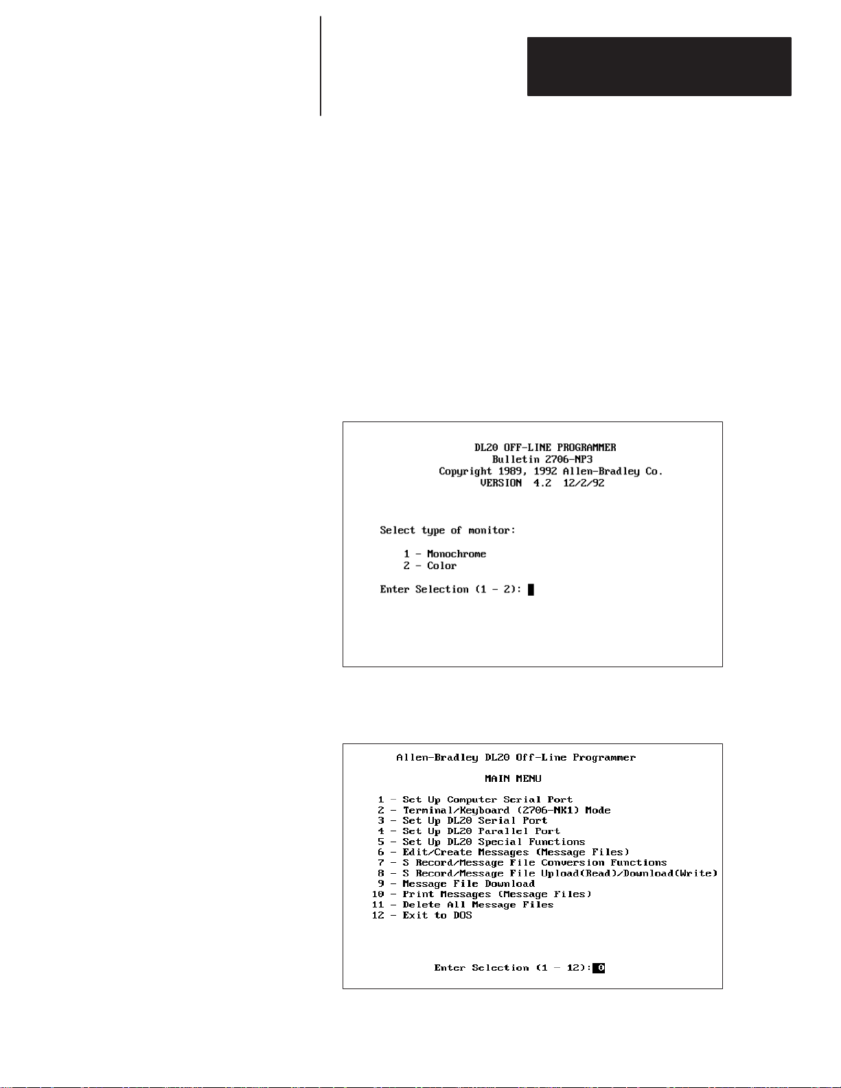
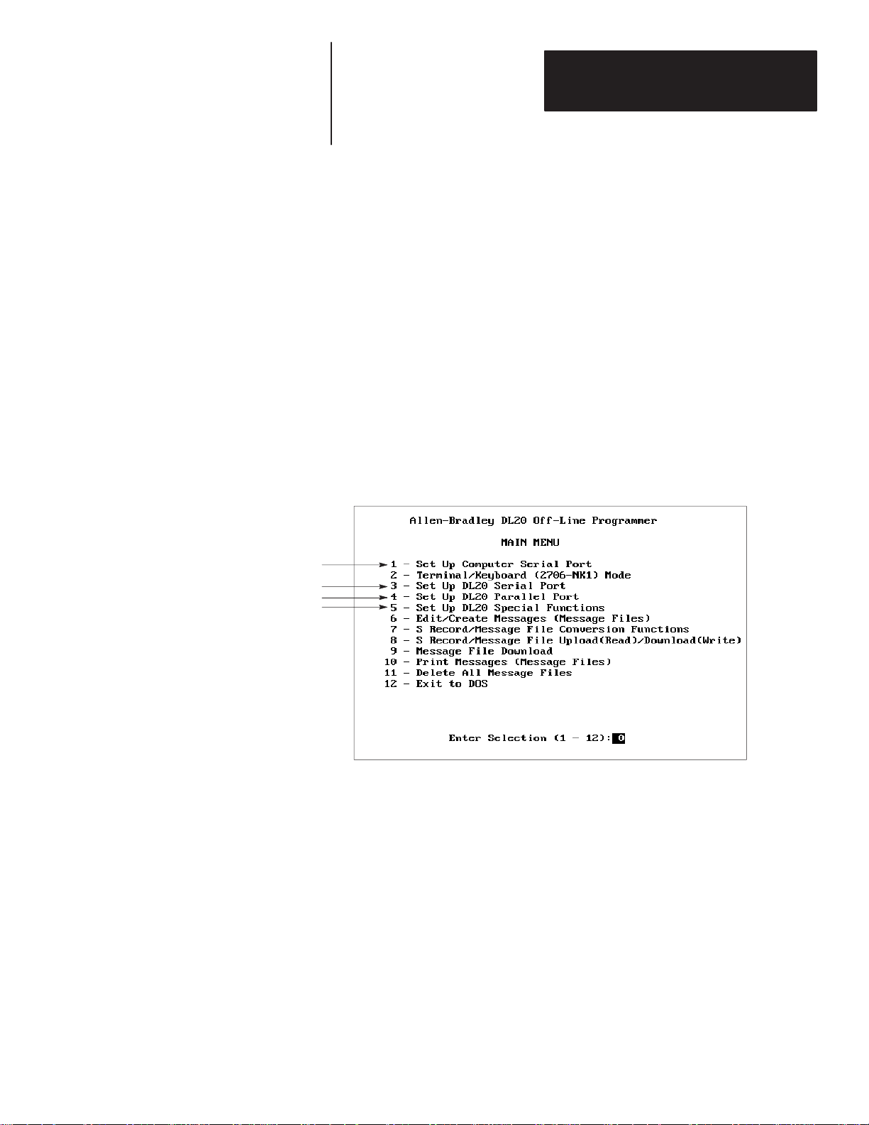
Each time you enter the programmer, this screen appears.
3. Select the type of monitor you are using by entering 1 or 2 and [Enter].
The Main Menu appears.
All menu functions are described in the remaining chapters of this manual.
3–5
Page 15
Chapter 3
Installing the Software
Exiting the DL20 Software
Function Keys
To exit the DL20 Software and return to DOS, select option 12 - Exit to Dos
from the Main Menu and press [Enter].
The DL20 Offline Programmer uses the same keys for most screen
operations. These keys and their functions are listed below. Keys that are
specific to an operation are noted when the operation is described.
Use This Key: To:
[Enter] or [Return]
or [ ]
←
[↑][↓]
[Esc] Cancels the current operation and returns to the Main Menu.
[End] Saves settings entered on a screen and in most cases returns
[←]
[0] - [9] Enters a number into a numeric data entry field.
[A] - [Z]
[a] - [z]
Accept a value in a field and move to the next field.
Move forward or backward through fields.
you to the Main Menu.
Moves cursor back one character and erases character.
Enters a letter into an alphanumeric data entry field.
DL20 Files
The DL20 creates a number of files during configuration and message
operations. The table below lists the files and their functions. These files are
transmitted to the DL20 during the download process.
File Name Description
MSG####.DAT Contains a single DL20 Message. The #### characters
represent a message number from 0001 to 1022.
MSG####.OLD Contains the old or previous version of a DL20 Message.
When a message is edited, the software automatically saves
the new file with a .DAT extension and the old version with the
.OLD extension. The filename (#### is the same for the new
and old version). The #### characters represent a message
number from 0001 to 1022.
CONFIG.DAT Stores DL20 configuration parameters including the DL20 type
(# of lines) and memory size.
DL20BAUD.OLP Stores baud rate and serial port setting your computer uses to
communicate with a DL20 or data recorder.
IOFILE.DAT Stores settings for the serial port of the DL20.
PIOFILE.DAT Stores settings for the parallel port of the DL20.
MSTRFILE.DAT Stores special function settings for the DL20.
SRECNAME.DAT Stores the name of an S Record file associated with
DL20 messages.
3–6
Page 16
Chapter
Chapter Objectives
What are the Configuration Functions?
A–B
4
Configuration Functions
This chapter shows how to use the DL20 Offline Programmer to configure:
• Serial communication port of your computer
• Serial port of the DL20
• Parallel port of the DL20
• Special functions of the DL20
The Main Menu has one function that configures the serial port of your
computer and three functions that configure the DL20 ports and DL20
special functions.
Functions 3, 4 and 5 create the following files which are downloaded with
messages to the DL20:
3 – Set Up DL20 Serial Port Creates IOFILE.DAT
4 – Set Up DL20 Parallel Port Creates PIOFILE.DAT
5 – Set Up DL20 Special Functions Creates MSTRFILE.DAT
The files are stored on disk or in the DL20 subdirectory. You are not allowed
to download messages to the DL20 without these files.
Each configuration function is described in the sections that follow.
4–1
Page 17
Chapter 4
Configuration Functions
Configuring the Computer Serial Port
To accept the default values
press [End] to save settings
and return to Main Menu.
Menu option 1 - Set Up Computer Serial Port sets the baud rate and
communication port your computer uses to communicate with a DL20 or
data recorder. These settings are stored in the file DL20BAUD.OLP on disk
or in the DL20 subdirectory and used when messages are transferred between
your computer and a DL20 or data recorder.
To configure the serial port of your computer:
1. Type 1 and press [Enter] to select 1 – Set Up Computer Serial Port
from the Main Menu.
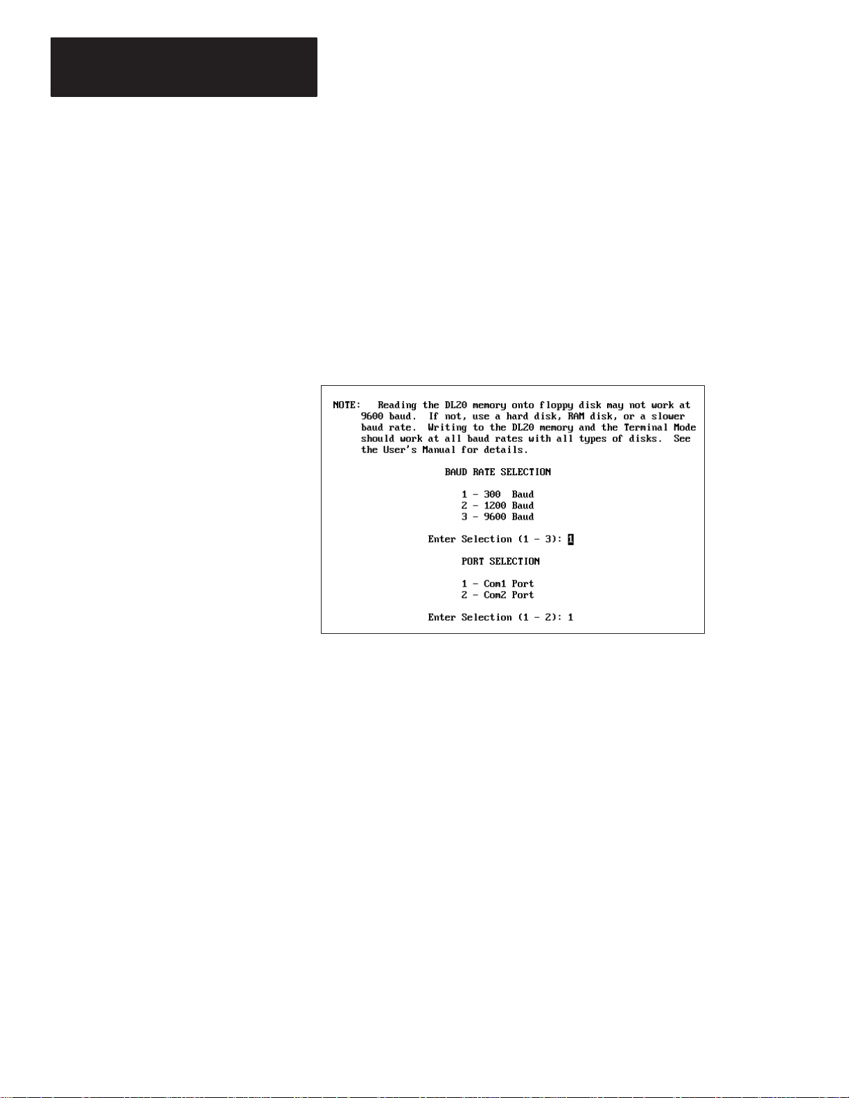
This screen appears.
4–2
2. Set the baud rate at which your computer will communicate with the
serial port of the DL20. The options are 300, 1200 and 9600. The initial
default is 300. Type 1, 2 or 3 and press [Enter].
Note: The serial port of the DL20 must be set to the same baud rate. See
the DL20 User Manual for details on how to do this.
3. Select the serial port on your computer that will connect to the DL20.
The options are Com1 or Com2. The initial default is Com1. Type 1
or 2 and press [Enter].
You return to the Main Menu.
Page 18
Chapter 4
Configuration Functions
Configuring the DL20 Serial Port
To accept the default values
press [End] to save settings
and return to Main Menu.
Menu option 3 - Set Up DL20 Serial Port sets parameters for the serial port
of the DL20. These settings are stored in the file IOFILE.DAT on your work
disk or DL20 subdirectory and transmitted to the DL20 at download.
To configure the serial port of the DL20 Display:
1. Type 3 and press [Enter] to select 3 - Set Up DL20 Serial Port
from the Main Menu.
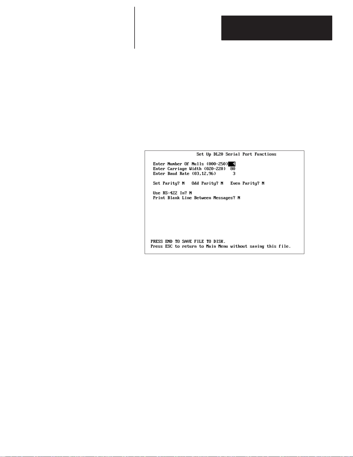
The following screen appears.
2. Specify the number of nulls to send to the printer after each line of text.
Valid values are 000 through 250. The default is 4. Press [Enter] to
accept the default or type another value and press [Enter].
3. Specify the carriage width or number of columns for printing. Valid
values range from 020 through 220 columns. The default is 80. Press
[Enter] to accept the default or type another value and press [Enter].
4. Specify the baud rate for the serial port of the DL20. Valid baud rates are
300, 1200 and 9600 (03 = 300, 12 = 1200, 96 = 9600). Press [Enter] to
accept the default of 300 or type another baud rate and press [Enter].
Important: The baud rate you enter does not take effect until settings are
downloaded to the DL20 and the DL20 is reset.
4–3
Page 19
Chapter 4
Configuration Functions
Configuring the
DL20 Serial Port
None
Odd
Even
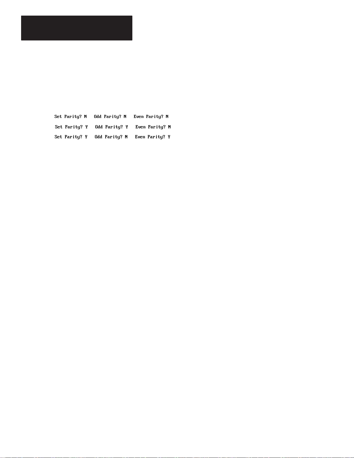
5. Specify the parity for the serial port of the DL20. The options are None,
Odd, or Even. The default is None or No Parity.
The examples below show the correct settings for each option.
Set Parity to N.
Set Parity to Y. Odd Parity is set to Y. Even Parity is set to N.
Set Parity to Y. Set Odd Parity to N. Even Parity is set to Y.
6. Set the RS-422 port direction. The default is RS-422 output. Press
[Enter] to accept the default. Type Y and press [Enter] to use the
RS-422 port as an input port.
7. Specify whether to print a blank line between messages. The default is N.
Press [Enter] to accept the default. Type Y and [Enter] to print blank
lines between messages.
8. Press [End] to save the DL20 serial port settings to the IOFILE.DAT file.
and return to the Main Menu.
Press [Esc] to quit and return to the Main Menu without saving changes.
For more information on the serial port settings of the DL20, refer to the
DL20 User Manual.
4–4
Page 20
Chapter 4
Configuration Functions
Configuring the
DL20 Parallel Port
To accept the default values
press [End] to save settings
and return to Main Menu.
Menu option 4 - Set Up DL20 Parallel Port sets parameters for the parallel
port of the DL20. The settings are stored in the file PIOFILE.DAT in the
DL20 directory and transmitted to the DL20 at download.
To configure the parallel port of the DL20 Display:
1. Type 4 and press [Enter] to select 4 - Set Up DL20 Parallel Port from
the Main Menu.
The following screen appears.
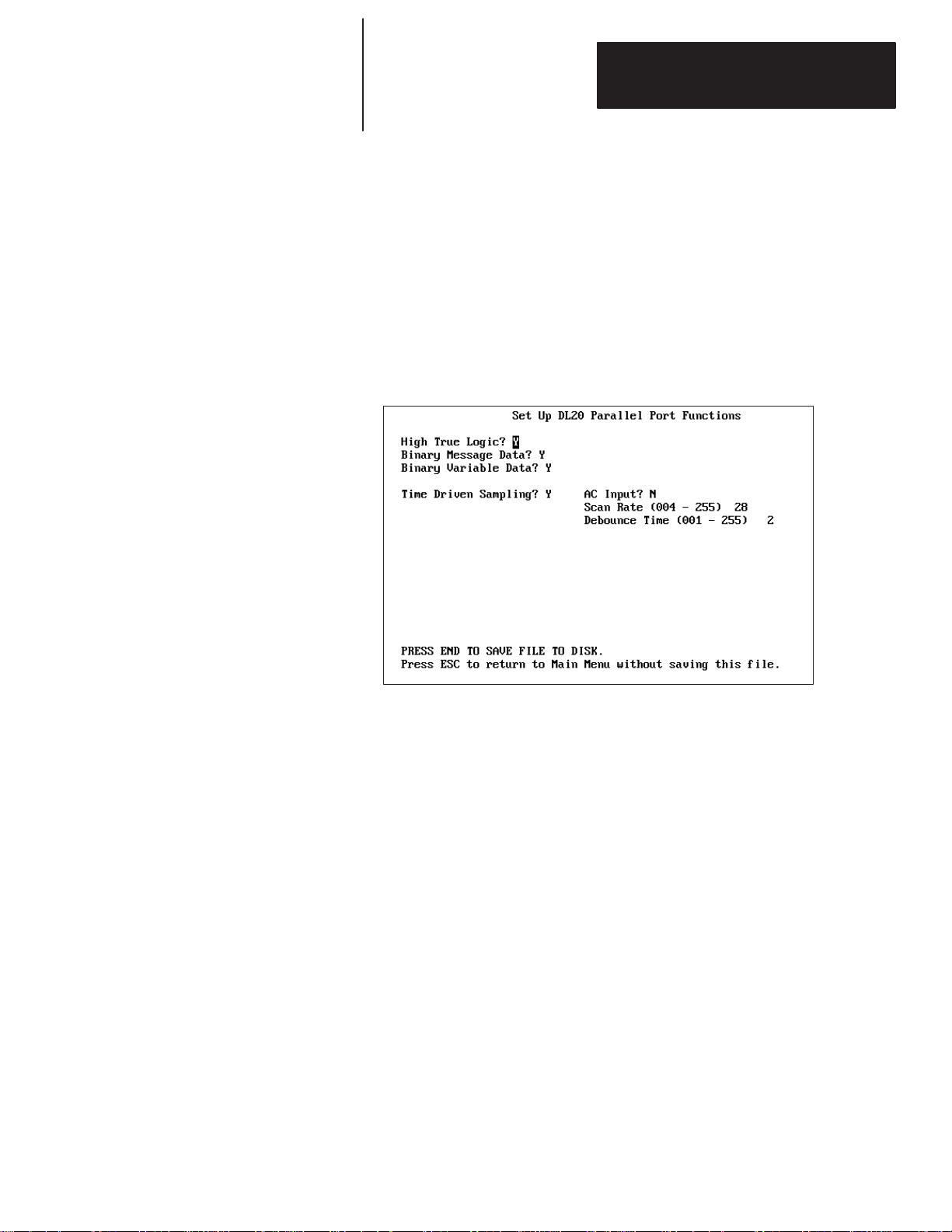
2. Specify whether the parallel port will use high true logic or low true logic
input levels. The default is high true logic. Press [Enter] to accept the
default. Type N and [Enter] to use low true logic.
3. Specify whether message triggers use binary or BCD format. The
default is binary message data. Press [Enter] to accept the default.
To use BCD format, type N and [Enter].
4. Specify whether variable data uses binary or BCD format. The
default is binary variable data. Press [Enter] to accept the default. To use
BCD variable data, type N and [Enter].
5. Specify whether the parallel port uses Time Driven or Event Driven
Sampling. To accept the default of Time Driven Sampling, press [Enter]
and skip to Step 9.
Note: Time Driven Sampling is recommended for use with
Allen-Bradley programmable controllers.
To specify Event Driven Sampling, type N and press [Enter].
4–5
Page 21
Chapter 4
Configuration Functions
Configuring the
DL20 Parallel Port
Ignore steps 9 – 12. They apply
only to Time Driven Sampling.
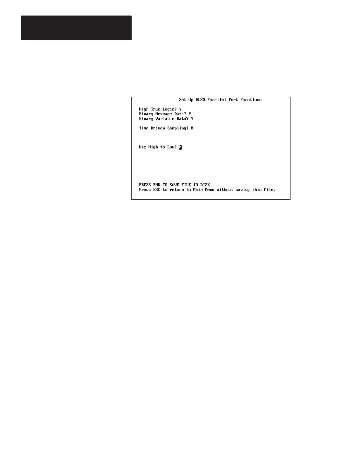
6. If Event Driven Sampling was selected in Step 5, the following screen
appears with the Use High to Low field highlighted.
7. Specify whether Event Driven Sampling will use high-to-low or
low-to-high transition. The default is low-to-high. To accept the default,
press [Enter]. To select high-to-low transition, type Y and [Enter].
8. Press [End] to save the DL20 parallel port settings to PIOFILE.DAT
and return to the Main Menu.
If you selected AC inputs
in Step 9, skip to Step 12.
4–6
Press [Esc] to quit and return to the Main Menu without saving changes.
9. Specify whether Time Driven Sampling will use AC or DC inputs.
The default is N which means to use DC inputs. Select DC inputs if using
the Catalog No. 2706-NG1 or -NG2 Input Converter (Series C). Press
[Enter] to accept the default.
Select AC Inputs if using the Catalog No. 2706-NG1 or -NG2 Input
Converter (Series A or B). To select AC inputs, type Y and press [Enter].
10. Specify the Scan Rate for Time Driven Sampling. Valid scan rates
for DC inputs range from 4 – 255. Valid scan rates for AC Inputs
are 28 - 255. The default scan rate is 28. To accept the default, press
[Enter]. Otherwise type another value and press [Enter].
11. Specify the debounce time for DC inputs. Valid time values range from
1 - 255 which correspond to real times of 1.95 milliseconds through 500
milliseconds. The default debounce value is 2. Press [Enter] to accept
the default. Otherwise, type another value and press [Enter].
12. Press [End] to save the DL20 parallel port settings to PIOFILE.DAT
You then return to the Main Menu.
Press [Esc] to quit and return to the Main Menu without saving changes.
For more information on the parallel port settings of the DL20, refer to the
DL20 User Manual.
Page 22

Chapter 4
Configuration Functions
Configuring Special Functions of DL20
Menu option 5 - Set Up DL20 Special Functions lets you:
• Specify an Autorun Message number.
• Specify a Background Message number.
• Specify a Master Address (for serial message triggering only).
• Enable/Disable Dynamic Message Chaining.
• Enable/Disable DL20 relay when batteries are detected as low.
• Enable/Disable the display of certain error messages.
Special Function settings are saved to the file MSTRFILE.DAT on disk or
the DL20 subdirectory. This file is transmitted to the DL20 at download.
For a complete description of DL20 Special Functions, refer to the DL20
User Manual.
To configure special functions for the DL20 Display:
1. Type 5 and press [Enter] to select 5 - Set Up DL20 Special Functions
from the Main Menu.
The following screen appears.
To accept the default values
press [End] to save settings
and return to Main Menu.
2. Enter a number to assign as the Autorun Message. Valid
message numbers range from 0 to 1022. The default is 0, which
means there is no autorun message. Press [Enter] to accept the default
or type another number and press [Enter].
3. Enter a number to assign as the Background Message. Valid
message numbers range from 0 to 1022. The default is 0, which
means there is no background message. Press [Enter] to accept the
default or type another number and press [Enter].
4–7
Page 23

Chapter 4
Configuration Functions
Configuring Special
Functions of DL20
4. Specify whether you want to enter a Master Address for triggering
messages. Valid responses are Y or N. The default is N which means a
master address is not set. To accept the default, press [Enter].
To specify a master address, type Y and [Enter]. This prompt appears:
Press [Enter] to accept the default address of 0 or type another address
in the range of 0 - 127 and press [Enter]. Invalid master address
values are listed on the screen.
5. Specify whether you want to enable Dynamic Message Chaining. Valid
responses are Y or N. The default of N disables dynamic message
chaining. To accept the default, press [Enter]. To enable dynamic
message chaining, type Y and [Enter].
6. Specify whether you want to enable a relay when the DL20 detects that
the lithium batteries are low. Valid responses are Y or N. The default of
N disables this function. To accept the default, press [Enter]. To enable a
relay, type Y and [Enter].
7. Specify whether you want to flag errors that are illegal message triggers
(invalid triggers for non-existent messages) or invalid variable triggers
for illegal numbers. Valid responses are Y or N. The default of N does not
flag errors. To accept the default, press [Enter]. To flag errors, type Y
and [Enter].
4–8
8. Press [End] to save the special function settings to MSTRFILE.DAT
and return to the Main Menu.
Press [Esc] to quit and return to the Main Menu without saving changes.
Page 24

Chapter
Chapter Objectives
How Messages are Stored
A–B
5
Message Operations
This chapter shows how to use the DL20 Offline Programmer to:
• Create new messages
• Edit existing messages
• Delete messages
• Copy messages
Messages created using the DL20 Offline Programmer are stored on disk or
in the DL20 subdirectory. Each message is stored in a separate file with the
name MSG####.DAT. The #### characters represent a message number
from 1 to 1022. For example:
MSG0001.DAT Message 1
MSG0002.DAT Message 2
MSG0003.DAT Message 3
.
.
.
MSG1021.DA T Message 1021
MSG1022.DA T Message 1022
Note: The first sixteen messages (1 – 16) store special DL20 messages.
When you edit and save an existing message, the original version of the
message is retained with the same file name but the .OLD extension. For
example, if you edit Message 20, the following two files reside on disk:
MSG0020.DA T new, edited file
MSG0020.OLD old, original file
If you prefer the old version of the message, delete the new message and
rename the old version. For example, to delete the edited version of Message
20 and retain the original version, type the commands below at DOS level.
C:\DL20>ERASE MSG0020.DAT [Enter]
C:\DL20>RENAME MSG0020.OLD MSG0020.DAT [Enter]
5–1
Page 25

Chapter 5
Message Operations
Creating New Messages
Menu option 6 - Edit/Create Messages lets you create new messages and edit
existing messages. This section shows how to create new messages.
Before creating messages for the DL20, you must specify the type of DL20
you are using and its memory size. This information is stored in the
CONFIG.DAT file on disk.
To create a new DL20 message:
1. Type 6 and press [Enter] to select 6 - Edit/Create Messages
(Message Files) from the Main Menu.
The first time you select this option, the following screen appears.
It prompts you for a disk name, the type of DL20 you are using and
its memory size.
2. Type a 1 to 16 character name to identify the disk or DL20 you are
programming and press [Enter]. You must enter a name in this field.
5–2
You can enter any ASCII character except the comma and
control codes.
Page 26

Chapter 5
Message Operations
3. Specify the DL20 type. Type 1, 2 or 4 and press [Enter].
(1 = 1 line display, 2 = 2 line display, 4 = 4 line display)
4. Enter the memory size of the DL20. Type 8, 16, or 31 and press
[Enter]. (8 = 8K, 16 = 16K, 31 = 31K)
Note: Valid memory sizes for the 1 and 2 line display are 8, 16, or 31.
The 4 line display supports memory sizes of 16 or 31.
5. Press [End] to save these DL20 parameters to CONFIG. DAT.
Important: Settings in CONFIG.DAT must be appropriate for your
DL20 or the download will not be successful.
You cannot edit the CONFIG.DAT file. You should erase
CONFIG.DAT before each editing session and create a new one to verify
that its settings are correct. Erase the file at DOS level not using menu
option 11 – Delete All Message Files. Option 11 erases all DL20 files.
DL20 Type and Memory Size
6. After saving CONFIG.DAT, the following screen appears. The
top of the screen shows the DL20 type and memory size just entered.
7. Press [Enter] at the Check DL20 Memory Used prompt. This
prompt will be explained in the next section on editing messages.
5–3
Page 27

Chapter 5
Message Operations
Creating
New Messages
New Message Attributes
8. Type a message number between 1 and 1022 and press [Enter].
It is recommended that you start at 20 since DL20 special messages
are numbered 1 – 16.
The screen displays the default attributes for new messages. The
attributes change relative to the display type.
9. Change attributes as appropriate. Use the ↑↓ arrow keys or [Enter]
to move from field to field. Table 5.A defines valid responses for
each attribute.
5–4
For a complete description of each attribute see the DL20 User Manual.
10. Press [End] when done to save the attribute settings.
To change attributes after they have been set ([End] pressed),
press [Ctrl] [A]. The first attribute field is highlighted.
You are now ready to enter the message text. Go to the next section.
Page 28

Table 5.A
Attribute
Vali
esponses
Message Attributes
Chapter 5
Message Operations
DL20 Line #
1 2 4
Auto Clear x x x Y or N
Auto Repeat x x x Y or N
Chain Message x x x Y or N
Energize Relay x x x Y or N
Flash Message x x x Y or N
Invisible Message x x x Y or N
Message Number
(for chaining to)
Out to Slave x x x
Print Message x x x
Scroll Mode x x x
Slave Number x x x
Stack Message x x x Y or N
To All Slaves x x x Y or N
Use All Lines x x
Use Line 1 Only x x
Use Line 2 Only x x
Use Least-Used Line x x
Use Line 3 Only x
Use Line 4 Only x
Wait Time x x x 0 to 31
➀ The Print Message and Out to Slave attributes are mutually exclusive. The DL20 serial port
can only be used for one function at a time. If one is set to Y, the other becomes N.
➁ Only one line attribute can be set to Y.
➂ If Scroll Mode is set to Y, Use All Lines is automatically forced to N.
➃ Slave Numbers 0,4,6,7,13,18,20,22,43,45, and 48–57 are illegal entries.
x x x 1 to 254
d R
Y or N ➀
Y or N ➀
Y or N ➂
1 to 127 ➃
Y or N ➁➂
Y or N ➁
Y or N ➁
Y or N ➁
Y or N ➁
Y or N ➁
5–5
Page 29

Chapter 5
Message Operations
Creating
New Messages
Entering Message Text
You can now enter message text. The message text area contains 16 blocks
(20 characters/block). The maximum message length is 320 characters.
After saving the message attributes, the first message block (of 20 characters)
is highlighted.
Message Block 1
16 Message Blocks
(20 characters/block)
To enter new message text:
1. Enter message text starting in block 1. The DL20 automatically centers
the message for display so you don’t need to enter extra spaces.
As you type text into the next block that block is highlighted.
The following keys are valid while entering or editing a message.
Press this Key: To:
[↓] or [PgDn] or [CTR] [J]
[↑] or [PgUp] or [CTR] [K]
[Ins] Insert one space character moving all charac-
[←] or [Ctrl] [H]
[→ ] or [Ctrl][L]
[Del] or [Ctrl] [D] Delete character at cursor position
[Ctrl] [A] Edit the message attributes.
[Esc] Abort the current message and return to the
[End] or [Ctrl] [Q] Save the message to a MSG####.DAT
Move forward one block.
Move back one block.
ters to the right one position.
Move cursor to the left one position.
Move cursor to the right one position.
shifting the entire message left one position.
Message Number prompt.
file and return to the Message Number prompt.
5–6
Page 30

Chapter 5
Message Operations
The screen below shows the text for Message 20 entered in the first
two blocks.
2. When finished entering the message text, press [End]. Message 20 is
automatically saved to file MSG0020.DAT.
The screen clears and returns you to the Message Number prompt. Type
another message number or press [End] to return to the Main Menu.
5–7
Page 31

Chapter 5
Message Operations
Editing Messages
Compares DL20 memory size
to actual memory usage.
Option 6 - Edit/Create Messages on the Main Menu also lets you edit
existing messages.
To edit a DL20 message:
1. Type 6 and press [Enter] to select 6 - Edit/Create Messages from the
Main Menu.
The following screen appears.
2. Each time you enter an edit session from the Main Menu, you are asked if
you want to check available DL20 memory.
Type Y and press [Enter] to check the available memory. Otherwise
press [Enter] to move to the next prompt.
If you enter Y, you are also asked to enter a range of message numbers for
the memory check.
For example, if you have 25 messages numbered from 1 to 25 you would
start at 1 and stop at 25.
3. Type the start message number and press [Enter].
4. Type the end message number and press [Enter].
5–8
Page 32

Chapter 5
Message Operations
The screen then shows the memory required for the range of messages
and the remaining free memory.
5. Press any key to return to the message screen.
6. Type the number of the message you want to edit and press [Enter].
The screen displays the message and attributes for the selected number.
If a message is converted to or from an S Record file, the screen will
show the Related S Record File name. Otherwise, this field is blank.
(Chapter 6 defines S Record Files.)
5–9
Page 33

Chapter 5
Message Operations
Deleting Messages
Menu option 11 – Delete All Message Files deletes all message files and the
following DL20 files from disk or the DL20 subdirectory:
• Message Files (MSG####.DAT, MSG####.OLD)
• Configuration File (CONFIG.DAT)
• Serial I/O File (IOFILE.DAT)
• Parallel I/O File (PIOFILE.DAT)
• Special Function File (MSTRFILE.DAT)
• S Record File Name File (SRECNAME.DAT)
To delete all DL20 Message Files:
1. Type 11 and press [Enter] to select option 11 – Delete all Message Files
from the Main Menu.
The following message appears.
2. Type Y and press [Enter] to delete all DL20 files.
The following message displays as the files are deleted.
5–10
You then return to the Main Menu.
Page 34

Chapter 5
Message Operations
Copying Messages
To create several messages that are the same or similar, you can use the DOS
COPY command to copy MSG####.DAT message files. For example, to
duplicate Message 20 and copy it into Message 21 use this command.
C:\DL20>COPY MSG0020.DAT MSG0021.DA T [Enter]
1 File Copied
Note: Your DOS prompt may look different.
Copied message files are stored on disk, like message files created with the
DL20 Offline Programmer.
To create a third identical message, press the [→] key and your computer
will duplicate the above command.
C:\DL20>COPY MSG0020.DAT MSG0021.DA T
Change the 1 in MSG0021.DAT to a 2 and press [Enter] as shown below.
This command copies Message 20 into Message 22.
C:\DL20>COPY MSG0020.DAT MSG0022.DA T [Enter]
1 file(s) copied
To copy multiple messages simultaneously, use the * (wild card character) in
place of a digit. For example the command:
C:\DL20>COPY MSG032*.DAT MSG033*.DA T [Enter]
10 file(s) copied
copies Message Numbers 320 through 329 into Message Numbers 330
through 339.
To make changes to any file you copy, enter the Offline Programmer and
select option 6 - Edit/Create Messages.
5–11
Page 35

Chapter
Chapter Objectives
Overview of Conversion Functions
A–B
6
Message File Conversions
This chapter shows how to:
• Convert DL20 message files to an S Record File
• Convert an S Record File to DL20 message files
• View DL20 files on disk
It is recommended that you convert all DL20 files to an S Record file. The S
Record file stores all message files (MSG####.DAT) and configuration files
(IOFILE.DAT, PIOFILE.DAT, MSTRFILE.DAT) in a single file.
Downloading an S Record file to a DL20 or data recorder is more efficient
and faster then downloading individual files. You can then delete the
original .DAT files to save disk space.
To print DL20 message files or to modify the configuration files, you must
convert the S Record file back to the individual DL20 message files. The
files are converted with their original names.
Menu option 7 – S Record/Message File Conversion Functions accesses the
file conversion functions.
Selecting option 7 displays the File Conversion Functions submenu.
6–1
Page 36

Chapter 6
Message File Conversions
Overview of
Conversion Functions
Converting Message Files to S Record File
From this submenu you can:
• Convert DL20 message files to an S Record file
• Convert an S Record file back to individual DL20 message files
• View all DL20 files and S Record files currently on disk
The sections that follow describe each function.
This section shows how to convert all DL20 message files (MSG####.DAT)
and configuration files (IOFILE.DAT, PIOFILE.DAT, MSTRFILE.DAT) to
an S Record file for downloading or storage.
You can convert messages of any size. However, only the first 16 blocks of
20 characters/block will be displayed when using menu option
6 – Edit/Create Messages.
If you are programming multiple Dataliners with different configurations and
messages, create a separate S Record file for each DL20. If using the same
configuration and messages for multiple DL20 Dataliners you only need one
S Record file.
The configuration files (IOFILE.DAT, PIOFILE.DAT, MSTRFILE.DAT)
must exist before you begin the conversion. These files are created with the
following Main Menu options.
6–2
3 – Set Up DL20 Serial Port Creates IOFILE.DAT
4 – Set Up DL20 Parallel Port Creates PIOFILE.DAT
5 – Set Up DL20 Special Functions Creates MSTRFILE.DAT
If these files do not exist, you will get an error message during the
conversion.
Page 37

Chapter 6
Message File Conversions
To convert DL20 files to an S Record file:
1. Select option 7 – S Record/Message File Conversion Functions from the
Main Menu.
2. Select option 2 - Convert MSG*.DAT Files to S Record File from the File
Conversion Functions submenu.
You are asked you to enter a name for the S Record file.
3. Type a 1 to 8 character name and press [Enter]. Do not enter a file
extension. You can include a drive letter in the name, e.g., A:DL20#1.
The conversion begins. The screen displays message numbers as
they are converted. At the end of the conversion, this message displays:
CONVERSION COMPLETED
4. Press any key to return to the Main Menu.
You can download the S Record file to a DL20 Dataliner or an Allen-Bradley
1770-SA or -SB Data Recorder.
The original MSG####.DAT and configuration files are still intact. You can
delete them to free up disk space.
When using Main Menu option 6 – Edit/Create Messages the screen will
display the name of the S Record file associated with the messages.
6–3
Page 38

Chapter 6
Message File Conversions
Converting S Record File to Message Files
You cannot modify DL20 configuration files or print messages that were
converted to an S Record file. To modify or print these files, you must first
convert the S Record file back to the individual DL20 files.
During the conversion you are prompted to delete all DL20 messages
currently on the drive. It is recommended that you do this to avoid
combining the converted message files with any files that exist.
To convert an S Record file to DL20 message files:
1. Select option 7 – S Record/Message File Conversion Functions from the
Main Menu.
2. Select option 1 - Convert S Record File to MSG*.DAT Files from the File
Conversion Functions submenu.
You are asked if you want to delete all message files that are
currently on disk or in the DL20 directory.
3. Type Y and press [Enter] to delete DL20 message files.
The following message appears.
6–4
You are then asked to enter the name of the S Record file to convert.
4. Type the name of an existing S Record file and press [Enter].
You are then asked to enter the type of DL20 (number of lines) the
messages were originally created for.
5. Type the number of lines 1, 2, or 4 and press [Enter].
The conversion begins. The screen displays the message numbers
as they are converted. At the end of the conversion, this message displays:
CONVERSION COMPLETED
6. Press any key to return to the Main Menu.
The converted message files and configuration files are restored to disk with
their original names. Messages may be padded with the ∼ character. Ignore
these characters. They are not transmitted to the DL20.
The S Record file is not deleted after the conversion but remains on disk.
When editing messages that have been converted, the Related S Record File
Name appears on the message edit screen.
Page 39

Chapter 6
Message File Conversions
Viewing DL20 Files
Option 3 - View File Names on the File Conversion Functions submenu lets
you display a list of DL20 files in the DL20 subdirectory (or another drive).
You can display the following types of DL20 files:
• S Record files
• Message files including DL20 configuration files (.DAT)
• Old message files (.OLD)
To view DL20 files:
1. Select option 7– S Record/Message File Conversion Functions from the
Main Menu.
2. Select option 3 - View File Names from the File Conversion Functions
submenu.
The following screen appears with S Record Files selected.
3. Select the type of DL20 files you want to view. You are only allowed to
view one type (S Record files, *.DAT files or *.OLD files). Type Y next
to the type of files you want to list and press [Enter].
4. Select the drive on which you want to search for the files.
To select a drive other than A, backspace [←] over A:, type another drive
letter followed by the colon (B: C: or D:) and press [Enter].
The screen then displays a list of files for the selected type. The next
page shows sample file listings.
5. Press [Esc] to exit and return to the File Conversion Functions submenu.
6–5
Page 40

Chapter 6
Message File Conversions
Viewing DL20 Files
S Record Files (*. )
Sample DL20 File Listings
Message Files (*.DAT)
6–6
Page 41

Chapter
Chapter Objectives
Accessing File Read/Write Functions
A–B
7
Transferring S Record Files
This chapter shows you how to:
• Download S Record File to a DL20 or Data Recorder
• Upload DL20 Memory to a Personal Computer
• Upload S Record File from Data Recorder to Personal Computer
• View DL20 Files on disk
Menu option 8 - S Record/Message File Upload (Read)/Download (Write)
lets you transfer S Record files between your computer and a DL20 or
data recorder (Catalog No. 1770-SA or -SB).
Important: It is recommended that you use option 8 to transfer files
between a computer and DL20. Transferring S Record files is more efficient
then downloading message files (menu option 9).
Selecting option 8 displays the File Read/Write Functions submenu.
7–1
Page 42

Chapter 7
Transferring S Record Files
Connecting Equipment
Personal Computer
Before transferring files between your computer and a DL20 or data
recorder, you must connect the equipment using the appropriate cable.
Connecting Personal Computer to DL20
The figure below shows the connection between your personal computer and
a DL20 Dataliner Display using the Catalog No. 2706-NC2 Cable.
DL20 Dataliner
SERIAL COMM PORT
RS
RS
RS
Catalog No. 2706-NC2 Cable
RS
422
232
422
–
OUT
+
456789
232
IN GND
+12
VDC
OUT
ATTENTION: Do not connect computer to DL20 when power is
applied to the DL20. Damage to DL20 could result.
!
7–2
1. Attach the 25-pin connector end of cable to the Com1 or Com2 serial
communication port of your computer.
If your computer’s serial port has 9 pins use an AT Adapter with
the 2706-NC2 cable.
2. Attach the three spade connectors on the other end of cable
to the same numbered terminals on the back of the DL20 display.
Important: The DL20 must be set to the same baud rate as the serial port
of your computer to establish communications.
3. Power on the DL20.
4. You can use menu option 2 - Terminal/Keyboard (2706-NK1 Mode) to
verify the communication link between the computer and DL20.
When the computer is connected to the DL20 Display you can transfer files
between the two devices. To download a file to the DL20, see page 7–4.
To upload a file from the DL20, see page 7–6.
Page 43

Chapter 7
Transferring S Record Files
Connecting Personal Computer to Data Recorder
The figure below shows the connection between an AT compatible personal
computer (9-pin serial port) and a Catalog No. 1770-SB Data Recorder using
the Catalog No. 1770-CAS cable. The required cable varies for the computer
type. Available cables are listed in Chapter 2.
To 120 VAC
Power Source
Catalog No. 1770-SB Data Recorder
ATTENTION: Do not connect computer to recorder when power
is applied to the recorder. Damage to the recorder could result.
AT Personal Computer
!
1. Attach 9-pin connector end of cable to the Com1 or Com2 serial
communication port of your computer.
2. Attach other end of cable to communication port on data recorder.
3. Power on data recorder. Power indicator should light.
When the computer is connected to the data recorder you can transfer
S Record files between the two devices. To download an S Record file to
the data recorder, see page 7–8. To upload an S Record file from the data
recorder, see page 7–10.
7–3
Page 44

Chapter 7
Transferring S Record Files
Downloading S Record File to DL20
This section shows how to download an S Record file from your computer to
a DL20 Display. DL20 message files are converted to an S Record file
using option 7 - S Record /Message File Conversion Functions.
Before starting the download:
• Your personal computer must be connected to the DL20 Display.
• You must know the name of the S Record file to download.
You can view all S Record files on disk by selecting option
5 - View File Names on the File Read/Write Functions submenu.
• Verify that the DL20 has enough memory to store the S Record file. To
check the file size, convert the file back to a message file using menu
option 7. Then select option 6 to ”Check Available DL20 Memory”.
Important: The DL20 must have enough memory to store the S Record
file or the messages in the DL20 may be altered.
To download an S Record file to a DL20:
1. Select option 8 - S Record Message File Upload (Read)/Download
(Write) from the Main Menu.
The File Read/Write Functions submenu appears.
7–4
Page 45

Chapter 7
Transferring S Record Files
2. Select option 2 - Write Disk File to DL-20 Memory.
The following screen appears.
3. Type the name of the S Record file to download and press [Enter]. You
can include a drive in the name (A:, B: , C: or D:).
The program verifies the format of all records in the file. The records
display on the screen as they are checked. OK appears next to
each record that is free of errors. For example:
You are then asked if you want to send the records.
4. Press [Enter] to download the records. Otherwise type N and press
[Enter] to return to the Main Menu.
When the download is done, you return to the Main Menu. To abort the
download at any time, press [Ctrl][Z].
7–5
Page 46

Chapter 7
Transferring S Record Files
Uploading DL20 Memory to Personal Computer
This section shows how to transfer DL20 memory contents to an S Record
file on your personal computer. The S Record file is created during
the transfer.
Option 1 - Read DL-20 Memory to Disk File serves the same purpose as the
DL20’s tape read function with a Catalog No. 1770-SB Data Recorder. This
option is easier to use because the program handles all communication with
the DL20 and you do not need to respond to any of the DL20 prompts.
Before starting the upload, make sure your personal computer is connected to
the DL20 Display as described on page 7–2.
To upload DL20 memory to your computer:
1. Select option 8 - S Record/Message File Upload (Read)/Download
(Write) from the Main Menu.
The File Read/Write Functions submenu appears.
7–6
2. Select option 1 - Read DL-20 Memory to Disk File.
The following screen appears.
Page 47

Chapter 7
Transferring S Record Files
3. Type a 1 to 8 character name of the file to receive the data and
press [Enter]. Do not enter a file extension. You can include a drive
letter in the name, e.g., A:DL20#1.
If the file exists, this message appears.
Type Y and press [Enter] to overwrite file; otherwise press [Enter] to
provide a different file name.
The upload operation reads data from the DL20 memory and writes
records to the specified file. The records display on the screen as they
are received. To abort the operation and return to the Main Menu, press
[Ctrl][Z].
When the transfer is complete, each record is verified. OK appears next
to each record that is free of checksum errors. If the entire file is free of
errors, you will briefly see the message ALL OKAY and return to the
Main Menu.
Note: This operation does not perform a file to file comparison
of data.
7–7
Page 48

Chapter 7
Transferring S Record Files
Downloading S Record File to Data Recorder
This section shows how to transfer an S Record file to a 1770-SB Recorder
for storage or for downloading the same messages to multiple DL20 displays.
Before starting the download:
• The recorder must be connected to your computer and powered on as
described on page 7–3.
• You must know the name of the S Record file to download.
You can view all S Record files on disk by selecting option
5 - View File Names off the File Read/Write Functions submenu.
To download an S Record file to a data recorder:
1. Select option 8 - S Record Message File Upload (Read)/Download
(Write) from the Main Menu.
The File Read/Write Functions submenu appears.
7–8
2. Select option 4 - Write Disk File to 1770-SB Cartridge.
The following screen prompts you for an S Record file name. It also
shows the selected baud rate and communication port.
3. Set baud rate of data recorder to same baud rate shown on screen.
4. Verify that a tape cartridge is installed in data recorder.
Page 49

Chapter 7
Transferring S Record Files
5. Set the ”Track Select Switch” to the correct setting on the recorder.
6. Type the name of the S Record file you want to download and press
[Enter]. You can include a drive in the name (A: B: C: or D:).
The program verifies the format of all records in the file. The records
display on the screen as they are checked. OK appears next to
each record that is free of errors. For example:
You are then asked if you want to send the records.
7. Press [Enter] to send the records. If you type N, you return to the
Main Menu.
After pressing [Enter], the following message appears:
The ”Record on Tape” indicator lights when the download begins.
Records are displayed on the screen as they are downloaded.
You can abort the download at any time by pressing [Ctrl][Z].
When the download is done you return to the Main Menu.
7–9
Page 50

Chapter 7
Transferring S Record Files
Uploading File from Data Recorder
This section shows how to transfer an S Record file from a 1770-SB Data
Recorder to a personal computer.
Before starting the upload, make sure the recorder is connected to your
computer as described on page 7–3.
To upload an S Record file from the data recorder to your computer:
1. Select option 8 - S Record/Message File Upload (Read)/Download
(Write) from the Main Menu.
The File Read/Write Functions submenu appears.
7–10
2. Select option 3 - Read 1770-SB Cartridge to Disk File.
The following screen appears. It prompts you to type the name of an S
Record file to receive the data.
3. Set the baud rate of the data recorder to same baud rate shown on screen.
4. Verify that a tape cartridge is installed in the data recorder.
5. Verify that the ”Track Select” switch on the recorder is set to the
correct track.
Page 51

Chapter 7
Transferring S Record Files
6. Type the name of an S Record file and press [Enter].
If the file exists, this message appears.
Type Y and press [Enter] to overwrite file; otherwise press [Enter] to
provide a different file name.
The following message appears:
The ”Read from Tape” indicator lights when the upload begins.
Records are verified for the correct format and then displayed on the
screen as they are downloaded.
You can abort the upload at any time by pressing [Ctrl][Z].
When the download is done, the message ALL OKAY appears briefly
and you return to the Main Menu.
7–11
Page 52

Chapter 7
Transferring S Record Files
Viewing DL20 Files
Option 5 - View File Names on the File Conversion Functions submenu lets
you display a list of DL20 files in the DL20 directory (or another drive).
You can display the following types of DL20 files:
• S Record files
• Message files including DL20 configuration files (.DAT)
• Old message files (.OLD)
To view DL20 files:
1. Select option 8 - S Record/Message File Upload (Read)/Download
(Write) from the Main Menu.
7–12
2. Select option 5 - View File Names from the File Read/Write
Functions submenu.
The following screen appears with S Record files selected.
Page 53

Chapter 7
Transferring S Record Files
3. Select the type of DL20 files you want to view. You are only allowed to
view one type (S Record files, *.DAT files or *.OLD files). Type Y next
to the type of files you want to list and press [Enter].
4. Select the drive on which you want to search for the files.
To select a drive other than A, backspace [←] over A:, type another drive
letter followed by the colon (B: C: or D:) and press [Enter].
The screen then displays a list of files for the selected type. Below are
sample file listings.
5. Press [Esc] to exit and return to the File Read/Write Functions menu.
S Record Files (*. )
Message Files (*.DAT)
7–13
Page 54

Chapter 7
Transferring S Record Files
Helpful Hints
If you are having problems downloading or uploading, check the following:
• Verify Cable Connections
Make sure the cable is securely connected to the serial communication
port (Com1 or Com2) of your computer and the serial RS-232 port of
the DL20 or the 1770-SB Recorder.
• Verify Serial Port on Computer
Verify that the cable is connected to the same serial port (Com1 or Com2)
selected using menu option 1 - Set Up Computer Serial Port.
• Check Baud Rate
Your computer must be set to the same baud rate as the DL20 or 1770-SB
Data Recorder. Check the baud rate of your computer using menu option
1 - Set Up Computer Serial Port.
• Check Earth Ground Connection
Verify that the DL20’s earth ground (E. GND) is connected to earth
ground (preferably to the same ground as your computer).
• Check Communication Link
Select menu option 2 - Terminal/Keyboard (2706-NK1) Mode to verify
that a communication link exists.
• Check CONFIG.DAT File
Verify that your CONFIG.DAT file is configured for the same number of
lines as the DL20 to which you are downloading.
Use the DOS Type command to display the CONFIG.DAT file. The first
line displays the DL20 type (number of lines) the messages were
configured for.
• Check Available RAM in Computer
Make sure your computer has enough RAM for the messages being
downloaded or you may get a Device I/O error. Check the size of your
messages using menu option 6 - Edit/Create Messages (Message Files).
• Check ”Echo All to Slaves” Parameter on DL20
This parameter must be set to N. Check setting using menu option
2 - Terminal/Keyboard (2706-NK1) Mode and going to the Set up Master
Special Function within the display editor.
• Disable Internal Modem (if necessary)
Verify that internal modem (e.g., internal modem of 1784-T45) is
disabled. Refer to DOS manual.
• Check Track Setting on Data Recorder
If reading files to disk from a recorder, verify that the ”Track Select”
switch is set to the correct track.
7–14
Page 55

Chapter
Chapter Objectives
Connecting to DL20
A–B
8
Downloading Message Files
This chapter shows how to use menu option 9 - Message File Download to
download message files from a computer to a DL20 Display.
Note: It is recommended that you use option 8 - S Record/Message File
Upload (Read)/Download (Write) to download large numbers of messages.
The S Record file transfer is more efficient and faster.
Before transferring files between your computer and a DL20 Display, you
must connect the equipment using the appropriate cable. The figure below
shows this connection using the Catalog No. 2706-NC2 Cable.
DL20 Dataliner
Personal Computer
SERIAL COMM PORT
Catalog No. 2706-NC2 Cable
RS
422
RS
RS
RS
232
422
–
OUT
+
456789
232
IN GND
+12
VDC
OUT
ATTENTION: Do not connect computer to DL20 when power is
applied to the DL20. Damage to DL20 could result.
!
1. Attach the 25-pin connector end of cable to the Com1 or Com2 serial
communication port of your computer.
2. Attach the three spade connectors on other end of cable
to the same numbered terminals on the back of the DL20 display.
Important: The DL20 must be set to the same baud rate as the serial port
of your computer to establish communications.
3. Power on DL20.
4. You can use menu option 2 - Terminal/Keyboard (2706-NK1 Mode) to
verify communication link between the computer and DL20.
8–1
Page 56

Chapter 8
Downloading Message Files
Downloading
Message Files
This section shows how to use option 9 - Message File Download on the
Main Menu to download message files.
This option allows you to download:
• All DL20 Files including:
- MSTRFILE.DAT (DL20 special function file)
Created with menu option 5 - Set Up DL20 Special Functions
- IOFILE.DAT (DL20 serial port configuration)
Created with menu option 3 - Set Up DL20 Serial Port
- PIOFILE.DAT (DL20 parallel port configuration)
Created with menu option 4 - Set Up DL20 Parallel Port
- MSG####.DAT (all DL20 message files)
Created with menu option 6 - Edit/Create Messages (Message Files)
If downloading a large number of message files this option is faster than
downloading selected DL20 files.
• DL20 Special Function File only (MSTRFILE.DAT)
• Selected Message Files
Important: DL20 memory is cleared before files are downloaded when
sending all messages and special functions.
8–2
Page 57

If the CONFIG.DAT file does not
exist another screen will appear
first prompting you for the DL20
type and memory size.
Chapter 8
Downloading Message Files
To download message files to the DL20:
1. Select option 9 - Message File Download from the Main Menu.
The following screen appears.
The procedures below show what selections to make for each of the
download options.
If an S Record file exists for the messages being downloaded, the screen
displays the name of the file.
Downloading All Files
1. Type Y and [Enter] at the first prompt to download all files
including message files, configuration files and the special function file.
The download begins. The screen displays a message verifying that the
special functions file will be downloaded. As each message file is
downloaded, the screen displays the message number, message contents
and the number of lines the message will occupy.
Press [Esc] to stop the download and return to the Main Menu. The
current message will finish downloading before the download is aborted.
2. Press [End] when the download is complete to return to the Main Menu.
8–3
Page 58

Chapter 8
Downloading Message Files
Downloading
Message Files
Downloading Special Function File Only
1. Press [Enter] at the first prompt if you don’t want to send all files.
You are then asked if you want to send the Special Function file only.
2. Type Y and press [Enter] to send only the Special Function file.
The download begins. During the download, the screen displays the
message ”Sending Special Functions”.
3. When the download is complete, you can enter a range of messages to
send or press [End] to return to the Main Menu.
Downloading Selected Range of Files
1. Press [Enter] at the first prompt if you don’t want to send all files.
You are then asked if you want to send the Special Function file only.
2. Press [Enter] to download a selected range of message files without
the Special Function file.
You are then prompted to enter a range of numbers to download.
3. Enter the message number at which to start the download and press
[Enter]. The number must be in the range 1 - 1022.
4. Enter the last message number to download and press [Enter]. You must
enter a number that is equal to or greater than the start number.
As each message is downloaded, the screen displays the message number,
message contents and the number of lines the message will occupy.
You can press [Esc] at any time to stop the download and return to the
Main Menu. The current message will finish downloading before the
download is aborted.
8–4
5. When the download is complete you can enter another range of numbers
or press [End] to return to the Main Menu.
Page 59

Chapter 8
Downloading Message Files
Verifying Message Download
Helpful Hints
To verify that messages have been downloaded correctly, enter terminal
mode using menu option 2 - Terminal/Keyboard (2706-NK1) Mode and
check the messages in the DL20. For details on Terminal/Keyboard mode,
see Chapter 9 Using Terminal Mode.
If you are having problems with downloading, check the following:
• Verify Cable Connections
Make sure the cable is securely connected to the serial communication
port (Com1 or Com2) of your computer and the serial RS-232 port of
the DL20.
• Verify Communication Port
Verify that the cable is connected to the same communication port (Com1
or COM2) selected with menu option 1- Set Up Computer Serial Port.
• Check Baud Rate
The DL20 must be set to the same baud rate as the serial communication
port of your computer using menu option 1- Set Up Computer Serial Port.
• Check Earth Ground Connection
Verify that the DL20’s earth ground (E. GND) is connected to earth
ground (preferably to the same ground as your computer).
• Check Communication Link
Select menu option 2 - Terminal/Keyboard (2706-NK1) Mode to verify
that a communication link exists.
• Check CONFIG.DAT File
Verify that your CONFIG.DAT file is configured for the same number of
lines to which you are downloading.
• Check ”Echo All to Slaves” parameter on DL20
This parameter must be set to N. Check setting using menu option
2 - Terminal/Keyboard (2706-NK1) Mode and going to Set up Master
Special Function within the display editor.
8–5
Page 60

Chapter
Chapter Objectives
Connecting to DL20
A–B
9
Using Terminal Mode
This chapter shows how to use menu option 2 - Terminal/Keyboard
(2706-NK1) Mode to communicate with a DL20. This option allows your
computer keyboard to emulate a Catalog No. 2706-NK1 or -NK2 Keyboard.
Terminal/Keyboard mode is useful for:
• verifying a communication link between your computer and a DL20
• verifying messages after a download operation
• performing DL20 data entry and configuration functions
To use your computer in terminal/keyboard mode you must first connect to
the DL20 using the appropriate cable. The figure below shows this
connection using the Catalog No. 2706-NC2 Cable. It is identical to the
download connection in Chapter 8.
DL20 Dataliner
Personal Computer
SERIAL COMM PORT
Catalog No. 2706-NC2 Cable
RS
422
RS
RS
RS
232
422
–
OUT
+
456789
232
IN GND
+12
VDC
OUT
ATTENTION: Do not connect computer to DL20 when power is
applied to the DL20. Damage to DL20 could result.
!
1. Attach the 25-pin connector end of cable to the Com1 or Com2 serial
communication port of your computer.
If your computer’s serial port has 9 pins use an AT Adapter with
the 2706-NC2 cable.
2. Attach the three spade connectors on other end of cable to the
same numbered terminals on the back of the DL20 display.
Important: The DL20 must be set to the same baud rate as the serial port
of your computer to establish communications.
3. Power on DL20.
9–1
Page 61

Chapter 9
Using Terminal Mode
Entering Terminal Mode
To use your computer in terminal/keyboard mode:
1. Select option 2 - Terminal/Keyboard (2706-NK1) Mode from the
Main Menu.
The following screen appears showing the selected baud rate and the
communication port. You are now in terminal mode.
9–2
2. You can now use your keyboard to operate as a 2706-NK1 or -NK2
keyboard. Any key pressed on the keyboard is transmitted to the DL20.
Data you enter will appear on the DL20 Display but not on your
computer screen.
3. Press [End] to quit terminal mode and return to the Main Menu.
See the DL20 User Manual for details on how the Catalog No. 2706-NK1
or -NK2 Keyboards are used to communicate with and configure a
DL20 Display.
Page 62

Chapter
Chapter Objectives
Connecting Printer
A–B
10
Printing Messages
This chapter shows how to use menu option 10 - Print Messages (Message
Files) to print DL20 messages.
Before printing messages, you must first connect a printer to your computer’s
printer (LPT1) port using the appropriate cable.
Personal Computer
Communications Cable
Printer
The printer port is usually a parallel port. You can redirect the printer output
to a serial port such as Com1 or Com2 by typing the following commands at
DOS level.
MODE LPT1: =COM2 [Enter]
MODE COM2: 9600, N, 8, 1 [Enter]
These commands may vary depending on the computer and printer. Consult
your computer’s User Manual for the exact commands required.
10–1
Page 63

Chapter 10
Printing Messages
Printing Messages
If the CONFIG.DAT file does not
exist, another screen will appear
first prompting you for the DL20
type and memory size.
To print DL20 messages:
1. Select option 10 - Print Messages (Message Files) from the Main Menu.
The following screen appears prompting you for a range of message
numbers to print and other attributes.
10–2
2. Type the number of the first message you want to print and press [Enter].
Valid numbers are in the range 1 - 1022. The numbers 255, 256, 511,
512, 767 and 768 are ignored.
3. Type the number of the last message you want to print and press
[Enter]. Valid numbers are in the range 1 - 1022. The numbers 255, 256,
511, 512, 767 and 768 are ignored.
4. Specify whether you want to print message attributes with each message.
Type Y or N and press [Enter].
Page 64

Chapter 10
Printing Messages
5. Specify whether you want to print system attributes. Type Y or N
and press [Enter].
Printing starts. The screen displays the number of each message as it
prints. Only the messages in the current DL20 subdirectory or on disk
will be printed.
Press [Esc] to abort printing. The current message will finish printing
before you return to the Main Menu.
After all messages have printed you are asked if you want to delete them
from disk.
Important: Do not delete messages before saving or converting the
message files to an S Record file.
6. Type Y and [Enter] to delete messages. Otherwise, just press [Enter].
You return to the Main Menu.
10–3
Page 65

Appendix
A–B
A
Connection Diagrams
This appendix provides connection diagrams that you can use to
make your own cables.
Figure A.1
Connecting DL20 to an XT (25-Pin) Compatible Computer
DL20 RS-232 Serial Port
Lug Connections
RS-232 IN (Clear)
RS-232 OUT (Red)
Ground (Black)
7
6
8
25-Pin Serial Port
Computer COM1
SHIELD (frame ground)
1
2
TXD
3
RXD
7
Signal GND
The wire colors refer to the Allen-Bradley Catalog No. 2706-NC1 and -NC2 cables.
Figure A.2
Connecting DL20 to an AT (9-Pin) Compatible Computer
DL20 RS-232 Serial Port
Lug Connections
RS-232 IN (Clear)
RS-232 OUT (Red)
Ground (Black)
The wire colors refer to the Allen-Bradley Catalog No. 2706-NC1 and -NC2 cables.
The shield ground of the Adapter Cable should connect to Pin 1 at the computer end only.
Figure A.3
25-to-9 Pin Adapter Cable (Null Modem)
To 2706-NC2 or -NC7 Cable
(25-Pin D Shell Connector)
7
6
8
To Computer Serial Port
(9-Pin Female D Shell Connector)
9-Pin Serial Port
Computer COM1
SHIELD (frame ground)
1
2
RXD
3
TXD
5
Signal GND
2
3
7
Shielded cable is recommended for accurate data transmission
RCV
2
3
XMT
Signal GND
5
Signal GND
1
A–1
Page 66

Appendix A
IBM XT Serial Port
atalog No.
er
2
2
T
T
IBM AT Serial Port
atalog No.
er
Allen-Bradle
erial Port
atalog No.
er
Connection Diagrams
Figure A.4
Connecting 1770-SA or -SB Data Recorder to IBM XT Serial Port
(Equivalent to Catalog No. 1784-CXS Cable)
Figure A.5
Connecting 1770-SA or -SB Data Recorder to IBM AT Serial Port
(Equivalent to Catalog No. 1784-CAS Cable)
25-Pin D Shell Female Connector
1
2
TXD
RXD
3
4
RTS
5
CTS
6
DSR
GND
7
8
DCD
0
R
D
9-Pin D Shell Female Connector
3
TXD
RXD
2
7
RTS
8
CTS
6
DSR
GND
5
1
DCD
C
C
1770-SA or -SB Record
25-Pin D Shell Male Connector
1
2
TXD
RXD
3
4
RTS
5
CTS
6
DSR
GND
7
8
DCD
0
R
D
1770-SA or -SB Record
25-Pin D Shell Male Connector
Shield (frame ground)
1
2
TXD
RXD
3
4
RTS
5
CTS
6
DSR
GND
7
8
DCD
A–2
Figure A.6
Connecting 1770-SA or -SB Data Recorder to 6120 Serial Port
(Equivalent to Catalog No. 1784-CYS Cable)
4
DTR
y 6120 S
2
TXD
RXD
3
4
RTS
5
CTS
6
DSR
GND
7
8
DCD
9
DTR
9-Pin D Shell Female Connector
20
DTR
C
1770-SA or -SB Record
25-Pin D Shell Male Connector
Shield (frame ground)
1
2
TXD
RXD
3
4
RTS
5
CTS
6
DSR
GND
7
8
DCD
20
DTR
Page 67

Rockwell Automation helps its customers receive a superior return on their investment by bringing
together leading brands in industrial automation, creating a broad spectrum of easy-to-integrate
products. These are supported by local technical resources available worldwide, a global network
of system solutions providers, and the advanced technology resources of Rockwell.
Worldwide representation.
Argentina • Australia • Austria • Bahrain • Belgium • Bolivia • Brazil • Bulgaria • Canada • Chile • China, People’s Republic of • Colombia • Costa Rica • Croatia • Cyprus
Czech Republic • Denmark • Dominican Republic • Ecuador • Egypt • El Salvador • Finland • France • Germany • Ghana • Greece • Guatemala • Honduras • Hong Kong
Hungary • Iceland • India • Indonesia • Iran • Ireland •Israel • Italy • Jamaica • Japan • Jordan • Korea • Kuwait • Lebanon • Macau • Malaysia • Malta • Mexico •Morocco
The Netherlands •New Zealand • Nigeria • Norway • Oman • Pakistan • Panama • Peru • Philippines • Poland • Portugal • Puerto Rico • Qatar • Romania • Russia • Saudi
Arabia • Singapore • Slovakia • Slovenia • South Africa, Republic of • Spain • Sweden •Switzerland • T aiwan • Thailand • T rinidad • Tunisia • Turkey • United Arab Emirates
United Kingdom • United States • Uruguay • Venezuela
Rockwell Automation Headquarters, 1201 South Second Street, Milwaukee, WI 53204-2496 USA, T el: (1) 414 382-2000 Fax: (1) 414 38 2-4444
Rockwell Automation European Headquarters, Avenue Hermann Debroux, 46, 1160 Brussels, Belgium, Tel: (32) 2 663 06 00, Fax: (32) 2 663 06 40
Rockwell Automation Asia Pacific Headquarters, 27/F Citicorp Centre, 18 Whitfield Road, Causeway Bay, Hong Kong, Tel: (852) 2887 4788, Fax: (852) 2508 1846
World Wide Web: http://www.ab.com
Publication 2706–804 – April 1993
Supersedes Publication 2706–804 Dated December 1989
Copyright 1996 Allen-Bradley Company, Inc. Printed in USA
Publication 2706–804 – April 1993
40061-199-01(A)
 Loading...