

Page 1
Allen-Bradley
MessageBuilder
Configuration
User
Software
(Catalog No. 2706-MB1)
Manual
Page 2

Important User Information
Solid state equipment has operational characteristics differing from
those of electromechanical equipment. “Safety Guidelines for the
Application, Installation and Maintenance of Solid State Controls”
(Publication SGI-1.1) describes some important differences between
solid state equipment and hard–wired electromechanical devices.
Because of this difference, and also because of the wide variety of
uses for solid state equipment, all persons responsible for applying
this equipment must satisfy themselves that each intended
application of this equipment is acceptable.
In no event will the Allen-Bradley Company be responsible or liable
for indirect or consequential damages resulting from the use or
application of this equipment.
The examples and diagrams in this manual are included solely for
illustrative purposes. Because of the many variables and
requirements associated with any particular installation, the
Allen-Bradley Company cannot assume responsibility or liability for
actual use based on the examples and diagrams.
No patent liability is assumed by Allen-Bradley Company with
respect to use of information, circuits, equipment, or software
described in this manual.
Reproduction of the contents of this manual, in whole or in part,
without written permission of the Allen-Bradley Company is
prohibited.
Throughout this manual we use notes to make you aware of safety
considerations.
ATTENTION: Identifies information about practices
or circumstances that can lead to personal injury or
!
death, property damage, or economic loss.
Attentions help you:
• identify a hazard
• avoid the hazard
• recognize the consequences
Important: Identifies information that is especially important for
successful application and understanding of the product.
MessageBuilder and MessageView are trademarks of Alen-Bradley Company, Inc.
PLC and PLC–5 are registered trademarks of Allen-Bradley Company, Inc.
SLC 5/03, SLC 5/04, Dataliner and AdaptaScan are trademarks of Allen-Bradley Company, Inc.
INTERCHANGE is a trademark of Rockwell Software Inc.
Intel is a registered trademark of Intel Corporation.
MS-DOS and Microsoft Windows are registered trademarks of Microsoft Corporation.
Page 3

Preface
Table of Contents
Introducing MessageBuilder Configuration Software
Installing MessageBuilder Software
MessageBuilder Basics
Chapter 1
What is MessageBuilder? 1–1. . . . . . . . . . . . . . . . . . . . . . . . . . . . . . .
MessageBuilder Software Features 1–2. . . . . . . . . . . . . . . . . . . . . . . .
Typical Messages in an Application 1–5. . . . . . . . . . . . . . . . . . . . . . . .
Typical Message Contents 1–6. . . . . . . . . . . . . . . . . . . . . . . . . . . . . .
Chapter 2
System Requirements 2–1. . . . . . . . . . . . . . . . . . . . . . . . . . . . . . . . .
Installing MessageBuilder Software 2–2. . . . . . . . . . . . . . . . . . . . . . . .
INTERCHANGE Device Configuration Utility 2–7. . . . . . . . . . . . . . . . .
Troubleshooting the Installation Procedure 2–12. . . . . . . . . . . . . . . . . . .
Chapter 3
Windows Environment 3–1. . . . . . . . . . . . . . . . . . . . . . . . . . . . . . . . .
MessageBuilder Window 3–2. . . . . . . . . . . . . . . . . . . . . . . . . . . . . . .
Message Editor Table View 3–4. . . . . . . . . . . . . . . . . . . . . . . . . . . . . .
Opening and Closing Menus 3–7. . . . . . . . . . . . . . . . . . . . . . . . . . . . .
Status Bar and Toolbars 3–8. . . . . . . . . . . . . . . . . . . . . . . . . . . . . . . .
Message Editor Terminal View 3–10. . . . . . . . . . . . . . . . . . . . . . . . . . .
Dialogs 3–11. . . . . . . . . . . . . . . . . . . . . . . . . . . . . . . . . . . . . . . . . . . .
Getting Help 3–14. . . . . . . . . . . . . . . . . . . . . . . . . . . . . . . . . . . . . . . .
Planning an Application
Chapter 4
Design Checklist 4–1. . . . . . . . . . . . . . . . . . . . . . . . . . . . . . . . . . . . .
Safety Considerations 4–2. . . . . . . . . . . . . . . . . . . . . . . . . . . . . . . . .
Applications and Projects 4–3. . . . . . . . . . . . . . . . . . . . . . . . . . . . . . .
Messages 4–4. . . . . . . . . . . . . . . . . . . . . . . . . . . . . . . . . . . . . . . . . .
Controlling Devices 4–7. . . . . . . . . . . . . . . . . . . . . . . . . . . . . . . . . . .
Triggering a Message 4–9. . . . . . . . . . . . . . . . . . . . . . . . . . . . . . . . .
Slaving 4–15. . . . . . . . . . . . . . . . . . . . . . . . . . . . . . . . . . . . . . . . . . . .
Slave Device 4–18. . . . . . . . . . . . . . . . . . . . . . . . . . . . . . . . . . . . . . . .
Historical Event Stack 4–19. . . . . . . . . . . . . . . . . . . . . . . . . . . . . . . . .
Function Keys 4–20. . . . . . . . . . . . . . . . . . . . . . . . . . . . . . . . . . . . . . .
Function Key Types 4–23. . . . . . . . . . . . . . . . . . . . . . . . . . . . . . . . . . .
LED Indicators 4–25. . . . . . . . . . . . . . . . . . . . . . . . . . . . . . . . . . . . . . .
Handshaking 4–26. . . . . . . . . . . . . . . . . . . . . . . . . . . . . . . . . . . . . . . .
Publication 2706-817
Page 4

Table of Contentstoc–ii
Tags 4–31. . . . . . . . . . . . . . . . . . . . . . . . . . . . . . . . . . . . . . . . . . . . . .
Data Types 4–33. . . . . . . . . . . . . . . . . . . . . . . . . . . . . . . . . . . . . . . . .
Address Worksheet 4–35. . . . . . . . . . . . . . . . . . . . . . . . . . . . . . . . . . .
Defining Tags 4–36. . . . . . . . . . . . . . . . . . . . . . . . . . . . . . . . . . . . . . .
Scaling Data Display Variables 4–37. . . . . . . . . . . . . . . . . . . . . . . . . . .
Scaling Data Entry Variables 4–38. . . . . . . . . . . . . . . . . . . . . . . . . . . . .
Precision and Rounding 4–41. . . . . . . . . . . . . . . . . . . . . . . . . . . . . . . .
Communications Overview
Working with Application Files
Creating Messages
Chapter 5
MessageView 421 Terminal Ports 5–1. . . . . . . . . . . . . . . . . . . . . . . . .
RS-232 Port Communication 5–3. . . . . . . . . . . . . . . . . . . . . . . . . . . .
ASCII Triggering Commands 5–8. . . . . . . . . . . . . . . . . . . . . . . . . . . .
Remote I/O Communication 5–12. . . . . . . . . . . . . . . . . . . . . . . . . . . . .
Discrete I/O 5–15. . . . . . . . . . . . . . . . . . . . . . . . . . . . . . . . . . . . . . . . .
Block Transfer 5–17. . . . . . . . . . . . . . . . . . . . . . . . . . . . . . . . . . . . . . .
Chapter 6
Starting MessageBuilder 6–1. . . . . . . . . . . . . . . . . . . . . . . . . . . . . . .
Creating a New Application 6–2. . . . . . . . . . . . . . . . . . . . . . . . . . . . . .
Opening an Existing Application 6–4. . . . . . . . . . . . . . . . . . . . . . . . . .
Saving an Application 6–6. . . . . . . . . . . . . . . . . . . . . . . . . . . . . . . . . .
Renaming and Describing an Application 6–8. . . . . . . . . . . . . . . . . . . .
Closing an Application 6–10. . . . . . . . . . . . . . . . . . . . . . . . . . . . . . . . .
Exiting MessageBuilder 6–10. . . . . . . . . . . . . . . . . . . . . . . . . . . . . . . .
Chapter 7
The Message Editor Dialog 7–1. . . . . . . . . . . . . . . . . . . . . . . . . . . . . .
Working with Messages 7–2. . . . . . . . . . . . . . . . . . . . . . . . . . . . . . . .
Selecting Messages 7–3. . . . . . . . . . . . . . . . . . . . . . . . . . . . . . . . . . .
Editing Messages 7–5. . . . . . . . . . . . . . . . . . . . . . . . . . . . . . . . . . . .
Set Preferences 7–14. . . . . . . . . . . . . . . . . . . . . . . . . . . . . . . . . . . . . .
Message Editor Terminal View 7–16. . . . . . . . . . . . . . . . . . . . . . . . . . .
Embedded V ariables and Graphics 7–18. . . . . . . . . . . . . . . . . . . . . . . .
Numeric V ariable Display 7–23. . . . . . . . . . . . . . . . . . . . . . . . . . . . . . .
ASCII V ariable Display 7–26. . . . . . . . . . . . . . . . . . . . . . . . . . . . . . . . .
Numeric V ariable Entry 7–27. . . . . . . . . . . . . . . . . . . . . . . . . . . . . . . . .
ASCII V ariable Entry 7–30. . . . . . . . . . . . . . . . . . . . . . . . . . . . . . . . . .
Message Attributes 7–33. . . . . . . . . . . . . . . . . . . . . . . . . . . . . . . . . . .
Slaving 7–41. . . . . . . . . . . . . . . . . . . . . . . . . . . . . . . . . . . . . . . . . . . .
Function Keys 7–48. . . . . . . . . . . . . . . . . . . . . . . . . . . . . . . . . . . . . . .
LED Attributes 7–52. . . . . . . . . . . . . . . . . . . . . . . . . . . . . . . . . . . . . . .
Special Messages 7–54. . . . . . . . . . . . . . . . . . . . . . . . . . . . . . . . . . . .
Publication 2706-817
Page 5

Table of Contents toc–iii
Working with Tags
Managing Projects
Terminal and Communication Setup
Chapter 8
Using the Tag Editor 8–1. . . . . . . . . . . . . . . . . . . . . . . . . . . . . . . . . . .
Validating Tag Addresses 8–4. . . . . . . . . . . . . . . . . . . . . . . . . . . . . . .
Defining Tags 8–5. . . . . . . . . . . . . . . . . . . . . . . . . . . . . . . . . . . . . . .
Working With Tags 8–8. . . . . . . . . . . . . . . . . . . . . . . . . . . . . . . . . . . .
Finding Tags 8–11. . . . . . . . . . . . . . . . . . . . . . . . . . . . . . . . . . . . . . . .
Sorting Tags 8–12. . . . . . . . . . . . . . . . . . . . . . . . . . . . . . . . . . . . . . . .
Printing Tags 8–13. . . . . . . . . . . . . . . . . . . . . . . . . . . . . . . . . . . . . . . .
Tag Import/Export Utility 8–17. . . . . . . . . . . . . . . . . . . . . . . . . . . . . . . .
Chapter 9
About Projects 9–1. . . . . . . . . . . . . . . . . . . . . . . . . . . . . . . . . . . . . . .
Managing Projects 9–2. . . . . . . . . . . . . . . . . . . . . . . . . . . . . . . . . . . .
Managing Devices in Projects 9–5. . . . . . . . . . . . . . . . . . . . . . . . . . . .
Loading/Replacing Tags or Devices in a Project 9–7. . . . . . . . . . . . . . .
Restoring a Project 9–9. . . . . . . . . . . . . . . . . . . . . . . . . . . . . . . . . . .
Chapter 10
Overview of Terminal Setup 10–1. . . . . . . . . . . . . . . . . . . . . . . . . . . . .
Changing the Terminal Type 10–3. . . . . . . . . . . . . . . . . . . . . . . . . . . . .
Remote I/O Communications 10–4. . . . . . . . . . . . . . . . . . . . . . . . . . . .
Block Transfers 10–7. . . . . . . . . . . . . . . . . . . . . . . . . . . . . . . . . . . . . .
RS-232 Main Port Communications 10–9. . . . . . . . . . . . . . . . . . . . . . . .
Setting Advanced Terminal Options 10–12. . . . . . . . . . . . . . . . . . . . . . . .
Setting Format for Time and Date 10–18. . . . . . . . . . . . . . . . . . . . . . . . .
Defining Control Tags 10–21. . . . . . . . . . . . . . . . . . . . . . . . . . . . . . . . . .
Defining Status Tags 10–25. . . . . . . . . . . . . . . . . . . . . . . . . . . . . . . . . .
Auxiliary Port Setup 10–27. . . . . . . . . . . . . . . . . . . . . . . . . . . . . . . . . . .
Validating Applications and Transferring Files
Chapter 11
Helpful Hints 11–1. . . . . . . . . . . . . . . . . . . . . . . . . . . . . . . . . . . . . . . .
V alidating Applications 11–2. . . . . . . . . . . . . . . . . . . . . . . . . . . . . . . . .
Transfer Utilities 11–5. . . . . . . . . . . . . . . . . . . . . . . . . . . . . . . . . . . . .
Downloading an Application to a Terminal 1 1–6. . . . . . . . . . . . . . . . . . .
Downloading to a DOS file 1 1–8. . . . . . . . . . . . . . . . . . . . . . . . . . . . . .
Downloading Date/Time to Real Time Clock 1 1–9. . . . . . . . . . . . . . . . . .
Uploading an Application from a Terminal 11–10. . . . . . . . . . . . . . . . . . .
Uploading the Historical Event Stack 1 1–13. . . . . . . . . . . . . . . . . . . . . . .
Using the MessageView File Transfer Utility 1 1–15. . . . . . . . . . . . . . . . . .
Terminal Upgrade 11–18. . . . . . . . . . . . . . . . . . . . . . . . . . . . . . . . . . . .
Publication 2706-817
Page 6

Table of Contentstoc–iv
Creating Reports
Menus and Commands Summary
Tool Summary
Configuration Software Error and Warning Messages
Validation Error Messages
Chapter 12
Types of Reports 12–1. . . . . . . . . . . . . . . . . . . . . . . . . . . . . . . . . . . . .
Creating and Printing a Report 12–2. . . . . . . . . . . . . . . . . . . . . . . . . . .
Changing the Report Setup 12–3. . . . . . . . . . . . . . . . . . . . . . . . . . . . .
Previewing a Report 12–5. . . . . . . . . . . . . . . . . . . . . . . . . . . . . . . . . . .
Setting up a Printer 12–6. . . . . . . . . . . . . . . . . . . . . . . . . . . . . . . . . . .
Sending a Report to a File 12–7. . . . . . . . . . . . . . . . . . . . . . . . . . . . . .
Appendix A
Appendix B
Appendix C
Appendix D
Upload/Download Error Messages
Global Configuration Parameters
Tags and Data Types
Tag Address Worksheet
ASCII and Extended ASCII Characters
Glossary
Appendix E
Appendix F
Appendix G
Appendix H
Appendix I
Index
Publication 2706-817
Page 7

Welcome to MessageBuilder Configuration Software. You can use
this software to create control panel applications for MessageView
421 Operator Terminals.
MessageBuilder software allows you to create applications designed
specifically to control processes in your plant. When you load a
MessageBuilder application in a MessageV iew terminal, the terminal
displays messages that:
• give information about the operation
• ask for input to control the operation.
Registering Your Copy of MessageBuilder Software
Intended Audience
Your software registration card is located in the envelope with the
software disks. To register your software, mail the card to this
address:
Allen-Bradley
Global Technical Support
6680 Beta Drive
Mayfield Village, Ohio 44143.
Or fax the card to (216) 646-6770.
This manual is a resource to help you design message display
applications that will run in a MessageView 421 terminal. Since
there are many options designed to give a smooth-running operation
under any circumstances, you should become familiar with the
choices to be made.
MessageBuilder Configuration Software runs under Microsoft
Windows. You should know how to use a mouse, choose commands,
and work with windows and dialog boxes. To learn basic windows
techniques, read the User’s Guide that came with your Microsoft
Windows package.
PLC and SLC logic controllers and ASCII Triggering devices are
an important part of the systems that MessageBuilder applications
control. You should understand how controllers work, especially the
program and data files. See the user manuals for the controllers used
in your operation.
Publication 2706-817
Page 8
PrefaceP–2
Software Package
Conventions
The MessageBuilder Configuration Software package (Catalog No.
2706-MB1) comes with:
• 4 (3
1
/2 inch) installation disks
– 3 MessageBuilder Software disks (including
INTERCHANGE utility)
– 1 A-B Utilities disk.
• This manual: MessageBuilder Configuration Software manual
(Publication No. 2706-817).
• MessageView 421 Display Terminal user manual (Publication
No. 2706-816).
This manual uses the following conventions:
• Software or MessageBuilder software refers to the
MessageBuilder Configuration Software.
• Terminal refers to a MessageView 421 terminal.
• Windows (with a capital “W”) refers to Microsoft Windows or to
the Window menu in MessageBuilder. MessageBuilder windows
are written with a small “w”.
• Keys on the keyboard appear in boldface small capital letters:
– the Shift key (on the computer) appears as SHIFT in the text
– the Acknowledge key (on the terminal) appears as ACK.
☞ The Release.txt and Readmekt.txt
files contain the most recent
installation information.
Key combinations
• A hand with italicized text in the left margin gives helpful hints.
MessageBuilder software often gives a choice of methods for
selecting a command. Use the most convenient one.
• Select a tool on the toolbar.
A toolbar is displayed along the top of the screen specific to what
you are doing. Simply click on the appropriate tool and it is
activated. Appendix B illustrates all tools in all the toolbars.
• Use a key combination.
Certain commands in the File and Edit menus have a key
combination. Use it instead of selecting the command.
• Select a menu command.
Click the menu name and then the command name. Or press the
ALT key and the underlined letter of the menu name to drop the
menu, then type the underlined letter of the command. Appendix
A describes all commands in all the menus.
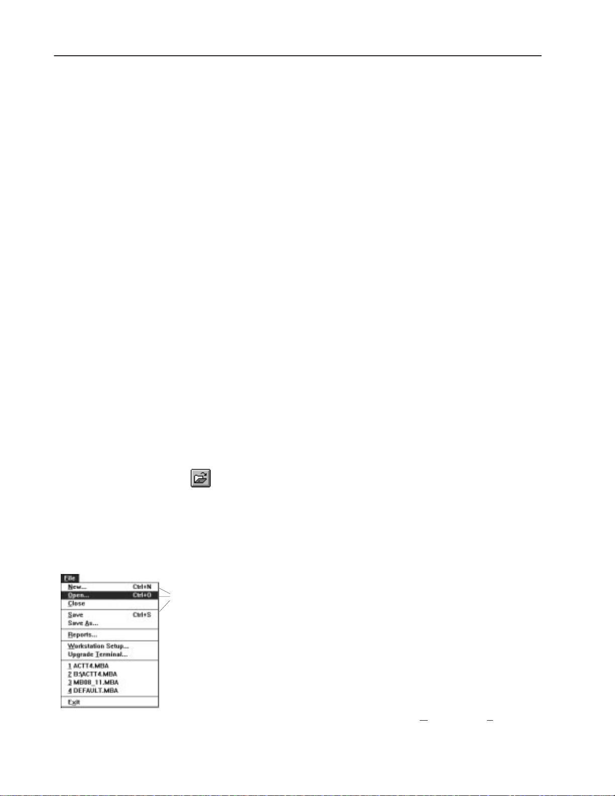
For example, to open an application from the initial MessageBuilder
screen, do one of the following:
– click on the Open File tool, or
– press CTRL + O, or
– type ALT + F then type O, to select Open from the File menu,
Publication 2706-817
and the File Open dialog appears.
Page 9

Preface P–3
Contents of the Manual
This manual is organized as follows:
Chapter Title Description
Preface
1
2
3 MessageBuilder Basics
4 Planning an Application
5
6
7 Creating Messages
Introducing
MessageBuilder Software
Installing MessageBuilder
Software
Communications
Overview
Working with Application
Files
Describes the purpose and contents of the
manual, and its intended audience.
Describes MessageBuilder Configuration
Software and some of its features.
Explains how to install MessageBuilder and
INTERCHANGE software on a personal
computer.
Explains how to use MessageBuilder
software’s menus, tools and dialogs. Also how
to use the Help system.
Gives guidelines for designing an application,
including safety considerations.
Gives guidelines for setting up MessageView
terminal communications.
Explains how to open and close
MessageBuilder software, and how to open,
close and save application files.
Shows how to create messages and set their
attributes. Also how to embed variables and
graphics in a message, and how function
keys work.
Related Publications
Explains how to use the Tag Editor feature of
8 Working with Tags
9 Managing Projects
10
11
12 Creating Reports Tells how to design a report and print it.
Terminal and
Communication Setup
Validating Applications
and Transferring Files
MessageBuilder software. Tags specify the
addresses in which variable data are stored.
Tells how to link a project to an application,
and how to copy, rename or delete projects.
Also shows how to work with devices in
projects.
Tells how to set operating and runtime
communication parameters for the
MessageView 421 terminal and a logic
controller.
Tells how to validate an application. Explains
several methods that transfer it between a
computer and a terminal or a disk file.
You should have the MessageView Display Terminal User Manual
(Publication No. 2706-816) at hand while creating an application.
Also refer as needed to the manual(s) for the controller the system
will be using.
Information and procedures relating to INTERCHANGE Software
and Microsoft Windows are given in this manual. For further details,
refer to the manuals for these products.
Publication 2706-817
Page 10

PrefaceP–4
Allen-Bradley Support
Local Product Support
Contact your local Allen-Bradley representative for:
• sales and order support
• product technical training
• warranty support
• support service agreements.
Technical Product Assistance
If you have questions about MessageBuilder Configuration software:
• check online Help
• review information on the subject in this manual
• review the release notes: these are separate icons in the
MessageBuilder Group in the Windows Program Manager
• review any technical notes on the subject that you have received
from Allen-Bradley.
If you still have a question, call your local Allen-Bradley
representative.
If you need more help, call:
Allen-Bradley
Global Technical Support
6680 Beta Drive
Mayfield Village, Ohio 44143.
Phone numbers:
• In the USA and Canada, call 1-800-289-2279.
• Outside the USA and Canada, call your local Allen-Bradley
office, or call USA (216) 646-6800.
• Fax number: (216) 646-6770.
Note: If you need to call Allen-Bradley for technical assistance,
please have the serial number of your software available. It may be
found in three places:
• on the software registration card
• on the welcome screen that appears when MessageBuilder starts
• in the main Help menu, choose About MessageBuilder to see the
About MessageBuilder dialog, which has:
– the release date and version number of MessageBuilder
software
– the release date and version number of the Allen-Bradley
Utilities software.
Publication 2706-817
Page 11

What is MessageBuilder?
Chapter
1
Introducing MessageBuilder
Configuration Software
This chapter covers the following topics:
• What is MessageBuilder?
• MessageBuilder software features
• Typical messages in an application
• Typical message contents.
MessageBuilder is a Microsoft Windows software package. An
application designer can use it to create custom applications for
MessageView 421N, 421F and 421D terminals.
MessageBuilder software makes creating an application as easy as
possible, by supplying dialog boxes, toolbars and menus. These
include:
• menus and toolbars keyed to the current situation
• dialogs to set up the computer workstation, the MessageView
terminal and the interface to controllers used in the process.
• dialogs in which applications and projects are created and edited
• the Message Editor Table View, in which messages are created
and edited
• the Message Editor Terminal View, which previews individual
messages
• the Tag Editor, in which tags are created and edited
• validation of the application before it is downloaded to a terminal,
and on command while the application is being created
• printer dialogs for making permanent records of specific or
general aspects of the application
• on-line and context-sensitive help.
Publication 2706-817
Page 12
1–2 Introducing MessageBuilder Configuration Software
MessageBuilder Software Features
MessageBuilder software has a number of features that make
designing an application easier.
Tool or Menu Operation
MessageBuilder software runs under Microsoft Windows. Many
functions can be performed using tools, keystrokes, or menu
commands. Use any or all, whichever you find most convenient.
Selectable Preferences
MessageBuilder lets you set features of the workspace window to
those you prefer. Options such as the Standard Toolbar and the Status
Bar can be toggled on or off, and remain in that state until you
change them. See Page 7–14 for other preferences. When you create
a new application or when you start a new session, MessageBuilder
uses the latest settings.
Status Bar Information
The Status Bar at the bottom of the screen explains what is
happening at the moment. See Page 3–8.
• If you hold the left mouse button down while the cursor is over a
tool, the status bar explains what it does.
• If a process is going on, the status bar reports on how it is doing.
The three spaces at the right end of the status bar give the status of
the keyboard
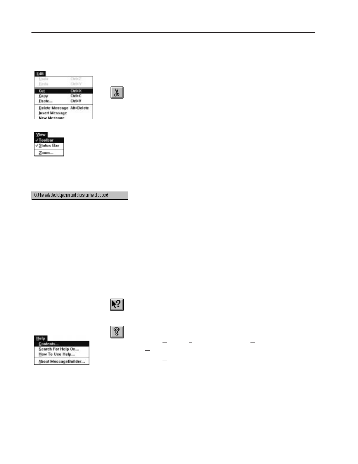
Help
The Help tools and commands provide a quick way to find
information about any part of MessageBuilder software. See Page
3–14 for a summary of the Help function. To access Help:
CAPS LOCK, NUM LOCK, and SCROLL LOCK keys.
• Click on the Help Question tool and then on an item or command
to get context–sensitive help.
• Press F1 to get specific help on a subject.
• The Help Contents tool displays an index to Help topics.
• Select Contents, Search For Help On, or How To Use Help on the
elp menu, depending on what you need to know.
H
• Select About MessageBuilder to find the copyright date and
version number of MessageBuilder software if you need to call
Allen-Bradley for assistance.
Publication 2706-817
Page 13
MessageView 421D
1–3Introducing MessageBuilder Configuration Software
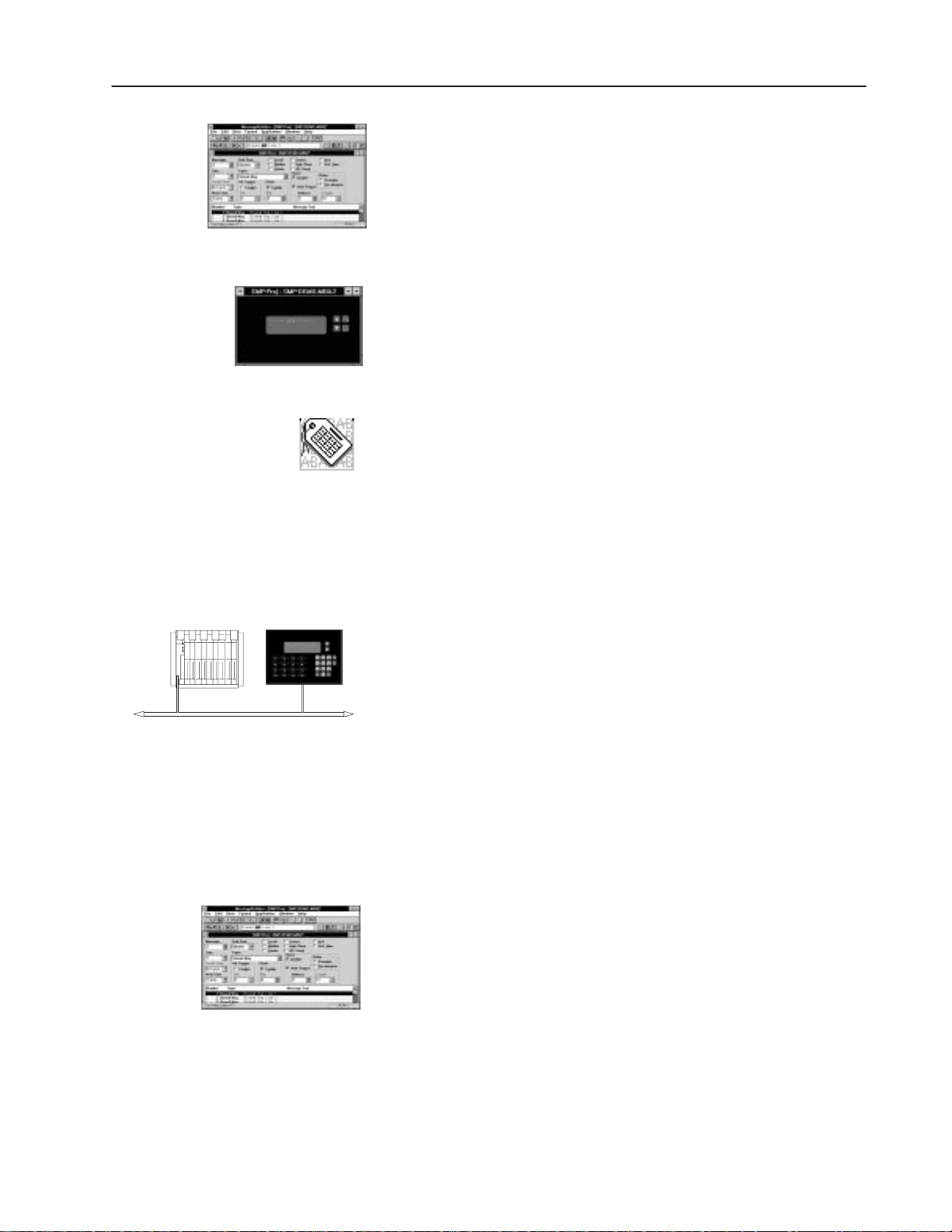
Message Editor Table View
Use this dialog to create and edit messages and their attributes used
in the application program.
The Message Editor Table View contains the menu commands and
tools needed to bring up all other dialogs, the Terminal View and the
Tag Editor.
Message Editor Terminal View
Use this view to view the current message, approximately as it will
appear in the MessageView terminal. An application is designed for
a certain type of terminal. The Terminal View displays the face of
that terminal type.
Tag Editor
Use the Tag Editor to enter, update, print, and import/export
application tags. See Chapter 8. Each variable requires a tag, which
defines how the variable interacts with a controller address.
PLC Controller MessageView 421 Terminal
✓
Enter all the tags at once in the Tag Editor Table View before starting
to create any messages. If a tag needs further editing when it is
assigned to a variable, use the Tag Editor Form View.
Terminal and Communication Setup
Access all operating and runtime communication parameters for the
MessageView 421 terminal from the Terminal Setup dialog. See
Chapter 10. These include:
• Remote I/O and RS-232 runtime communication parameters
• power-up defaults
• time/date display format
• control and status tags
• display settings, handshake timeout and trigger priority
• set up slaving or a slave device
• ASCII triggering.
Application Validation
Use validation to check all elements of the application for correct
input. See Chapter 11. When an application is downloaded to a
terminal, MessageBuilder software validates it automatically. You
can also validate the application at any time using the Validate menu
option. View warnings or errors detected during validation, or send
them to a printer or file.
Publication 2706-817
Page 14

1–4 Introducing MessageBuilder Configuration Software
Application Upload/Download Capabilities
Transfer applications between a MessageView 421 terminal and a
computer running either:
• MessageBuilder Configuration software
• MessageView File Transfer Utility.
See the section starting on Page 11–6.
Upload Historical Event Stack
The MessageView terminal maintains a running log of triggered
messages in a Historical Event Stack file. Upload this file from the
terminal to a computer that has either MessageBuilder software or
the File Transfer Utility installed. See the section starting on Page
4–19 for information on the Historical Event Stack, and on Page
11–13 for information on how to upload it to the computer for
analysis.
Reports
Use the report function to create customized reports for an
application. See Chapter 12. Reports may include any or all of the
following:
• application description
• messages
• message attributes
• terminal settings
• tags and their attributes
• function keys
• LED indicators.
Send reports to a printer supported by Microsoft Windows.
In addition to the report function, you may print information on tags
and their attributes via the Tag Editor (see Page 8–13).
Terminal Upgrade
Use the Upgrade Terminal command to upgrade the firmware in your
MessageView terminal(s). See Page 11–18.
Publication 2706-817
Page 15
1–5Introducing MessageBuilder Configuration Software
Typical Messages in an Application
An application contains messages. Messages may contain embedded
data variables, graphical symbols, and when designed for
MessageView 421F terminals, may have function keys enabled.
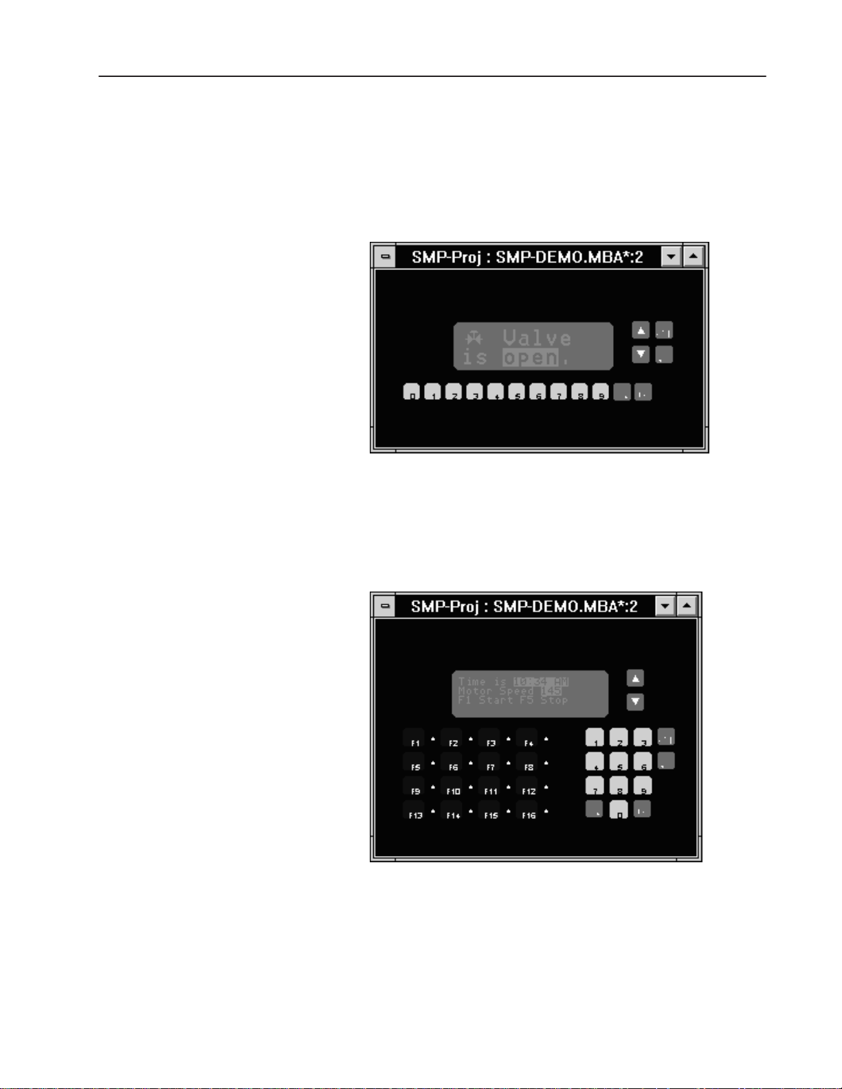
This example of a 421N Terminal View has a message that contains:
• a graphic symbol
• an ASCII Variable Display.
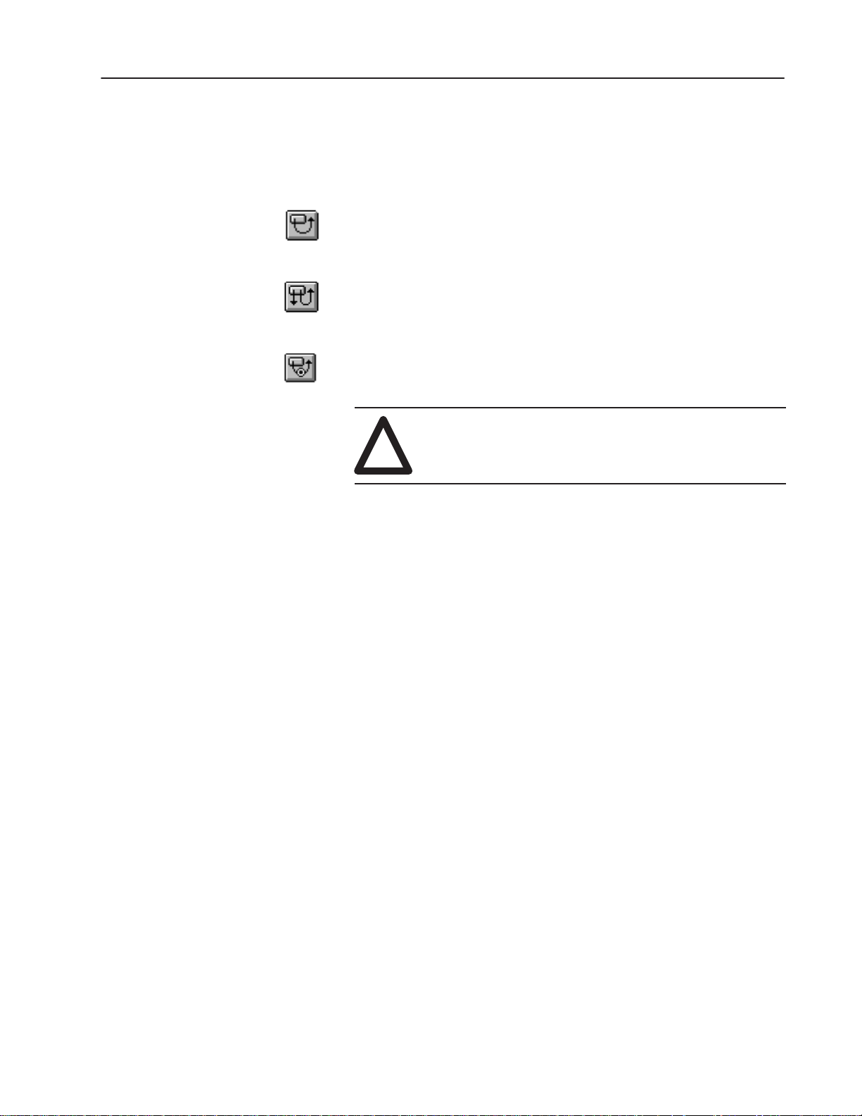
This example of a 421F Terminal View has a message that contains:
• a Time Variable
• a Numeric Variable Display
• enabled Function Keys.
Note: One message may occupy more than one line in the Terminal
View if the Line attribute is selected as “All”.
Publication 2706-817
Page 16

1–6 Introducing MessageBuilder Configuration Software
Typical Message Contents
Time or Date Display
Time is 16:23 CST.
Date is 06/24/96.
Pressure is 300 PSI.
Temperature Too High.
Enter Flow Rate:
Time Displays indicate the current time (hours, minutes and
seconds) according to the terminal’s Real Time Clock. Specify the
format of the display using the Terminal Setup dialog.
Date Displays indicate the current date (day, month and year)
according to the terminal’s Real Time Clock. Specify the format of
the display using the Terminal Setup dialog.
Set the Real Time Clock using the RTC Download command in the
Application menu.
Display Variables
Numeric Variable Displays shows the current value at a specific
controller address: binary, BCD or signed/unsigned integer. Scaling
(y = mx + b) may be used.
ASCII Variable Displays present status information to the terminal
operator according to the current character array at a specific
controller address.
Entry Variables
Numeric Variable Entries may be used in applications designed for
MessageView 421N and 421F terminals. These variables allow the
terminal operator to enter a numeric value from the terminal keypad.
Scaling (y = mx + b) may be used.
Bar Code Reading:
Publication 2706-817
V alve is open.
ASCII Variable Entries may be used in applications designed for
MessageView 421D, 421N and 421F terminals if the terminal
firmware can support these variables. These variables allow the
terminal operator to enter ASCII characters from an ASCII Input
device via the RS-232 port, or via the numeric keypad on the
terminal.
Graphics
Graphics consist of a set of 32 ISA symbols illustrating
manufacturing components such as motors and containers.
Page 17
1–7Introducing MessageBuilder Configuration Software
Function Keys
MessageView 421F terminals can use applications that have
Function keys enabled. An enabled function key is assigned to one of
these types:
A Momentary Function Key changes state when pressed and
changes back to the original state when its hold time has expired
after it is released.
A Maintained Function Key changes state when pressed and
remains in the changed state when released. It changes back to the
original state when the Function Key is pressed and released again.
A Latched Function Key changes state when pressed and remains
in that state until the controller unlatches it.
ATTENTION: Function Keys are active only when
they are enabled for a message currently displayed by
!
the terminal. All other Function Keys are non-active.
Example
Suppose a message has function keys F1, F5, and F9 enabled.
Whenever that message is displayed by the MessageView terminal,
these three keys are activated, but the 13 other Function keys remain
inactive.
When the message is terminated, the three Function keys are
inactivated at once.
Note: A Latched Function key remains in its changed state until the
controller unlatches it, but it is not active after its message is
terminated.
Publication 2706-817
Page 18

System Requirements
Chapter
Installing MessageBuilder
Software
This chapter covers the following topics:
• System requirements
• Installing MessageBuilder software
• INTERCHANGE Device Configuration Utility
• Troubleshooting the installation procedure.
The minimum hardware requirements for installing and running
MessageBuilder software are:
• a personal computer using Intel 386 or 486 processor or
equivalent
• a minimum 4 MB of memory (8 MB recommended) with
minimum of 10 MB permanent swap under virtual memory
• a hard disk with 12 MB of free space
• a 3.5 inch high-density (1.44 MB) disk drive
• a VGA or better monitor that is supported by Windows
• an RS-232 communications port
• a cable for downloading/uploading applications between the
computer and the RS-232 port of a MessageView 421 terminal.
Order Catalog No. 2706-NC13.
2
Also highly recommended are:
• a mouse compatible with Windows
• a printer that supports graphics, compatible with Windows.
The minimum software requirements for installing and running
MessageBuilder software are:
• MS-DOS operating system version 3.31 or later (MS-DOS
version 5.0 or later recommended)
• Microsoft Windows version 3.1 or later, or Windows for
Workgroups version 3.11 or later.
Note: MessageBuilder software utilizing INTERCHANGE V6.1
or later, is compatible with Microsoft Windows 95.
Publication 2706-817
Page 19

2–2 Installing MessageBuilder Software
Installing MessageBuilder Software
To install MessageBuilder Configuration Software:
1. Insert MessageBuilder software disk 1 in the appropriate
high-density floppy disk drive.
2. Start Windows (if necessary) by typing win at the DOS command
prompt and pressing
3. To start installing MessageBuilder:
ENTER.
• with Windows 3.1x, in the Program Manager window choose Run
from the F
ile menu (ALT + F, R)
• with Windows 95, in the Start menu choose Run (MS key + R)
4. In the command line box, type the drive letter of the drive
containing the MessageBuilder Software disk 1, followed by a
colon and the word setup. For example, type:
a:setup.
Then select OK or press
5. You are prompted to begin the MessageBuilder installation.
Select:
ENTER.
• Yes to continue
• No to cancel.
6. The installation software checks your system for AB Utilities
software.
If it detects an older version of AB Utilities software, it warns
you that the previous version will be deleted before the new
version is installed.
If it detects the same or a newer version of AB Utilities software,
it notifies you that there is no need to upgrade it.
7. If installation of AB Utilities is required, you are prompted to
install the AB Utilities Software:
• Insert the AB Utilities disk.
• Enter target drive and directory for installing files.
Recommended drive and directory is C:\AB.
The files are copied to the target directory.
8. Re-insert MessageBuilder software disk 1 to continue installing
the MessageBuilder software.
Publication 2706-817
Page 20

2–3Installing MessageBuilder Software
9. You are prompted to begin the MessageBuilder installation. The
installation software checks your system for MessageBuilder
software.
If it detects a previous
version of MessageBuilder software, it
warns you that the previous version will be deleted before the
new version is installed.
If it detects the same
version of MessageBuilder software, it gives
you the option of re-installing or deleting the files.
– Re-install writes over existing files
– Delete removes the files; you must then run the installation
again to install the new software.
10. Enter registration information: name, company name, and
product serial number. The serial number is on your registration
card.
11. Enter target drive and directory for installing files. Recommended
drive and directory is C:\AB.
The files are copied to the target directory.
12. Insert MessageBuilder disk 2 to install the remaining files.
13. You are prompted to install the INTERCHANGE software. Enter
target drive and directory for installing files.
Recommended drive and directory is C:\RSI\IC.
The files are copied to the target directory.
• If the installation detects a previous version of
INTERCHANGE, the procedure replaces existing components
with new components. The procedure will not overwrite
configuration files.
• If the installation detects the same version of
INTERCHANGE, you are allowed to reinstall the
components.
14. Insert MessageBuilder Disk 3 to install the remaining
INTERCHANGE files.
Publication 2706-817
Page 21

2–4 Installing MessageBuilder Software
15. The installation prompts you to update the AUTOEXEC.BAT
file. It adds:
– C:\AB\BIN to the path.
– C:\RSI\IC\BIN to the path.
– SHARE.EXE to the file (Windows 3.1x only).
– Environment variable ABIC_CONFIG=C:\RSI\IC\BIN.
– ABICRUN.BAT (starts INTERCHANGE software).
Important: MessageBuilder Configuration software and
Note: If you do not update your AUTOEXEC.BAT file during
MessageBuilder installation, MessageBuilder software writes the
changes to the file AUTOEXEC.EXM for future reference.
16. The INTERCHANGE Device Configuration Utility opens. Use
this utility to select and configure the “DF1 on COM Port”
communication drivers that your computer (workstation) will use
to transfer MessageView applications. See Page 2–8.
INTERCHANGE Software will not run without these
lines.
17. Review the release note that appears at the end of the installation
procedure.
18. When the installation is complete, you must exit Windows and
reboot your computer.
Publication 2706-817
Page 22
Installation Summary
MessageBuilder installation:
• copies MessageBuilder files to the hard disk under the target
drive and directory (C:\AB) or the location specified during
installation
• copies the AB Utilities files to disk under the target drive and
directory (C:\AB) or the location specified during installation
• copies INTERCHANGE files to disk under the target drive and
directory (C:\RSI\IC) or the location specified during installation
• adds SHARE.EXE to AUTOEXEC.BAT file (Windows 3.1x
only)
• adds C:\AB\BIN and C:\RSI\IC\BIN to path
• adds ABIC_CONFIG=C:\RSI\IC\BIN to AUTOEXEC.BAT,
which defines the location of the INTERCHANGE file
CFG_KT.INI
• adds MBWIN.INI and ISP.INI to the Windows directory
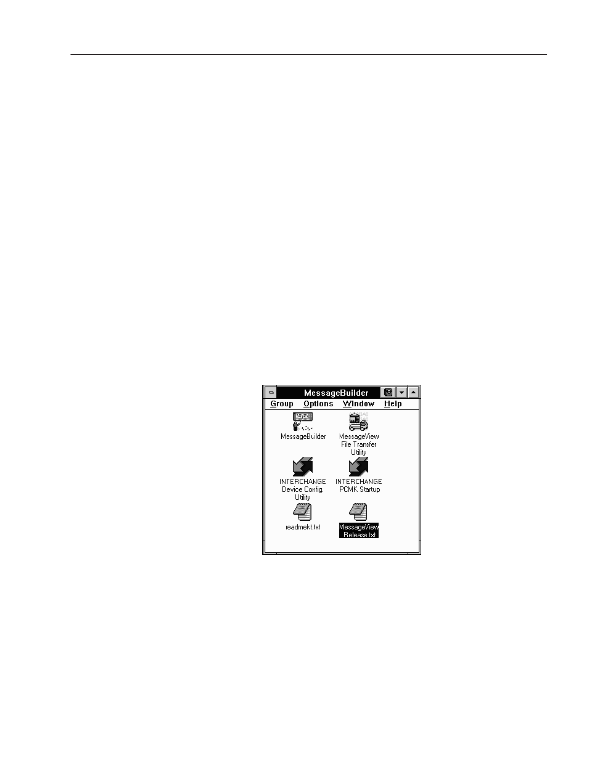
• creates a MessageBuilder group in the Program Manager
containing icons for MessageBuilder Software, the MessageView
File Transfer Utility, INTERCHANGE Device Config. Utility,
and the release notes.
2–5Installing MessageBuilder Software
Online Release Notes
Online release notes are available for the MessageBuilder
Configuration Software. These files contain the most recent
information on software and new functionality, proper configuration
and work arounds, and the organization of MessageBuilder files.
Publication 2706-817
Page 23

2–6 Installing MessageBuilder Software
Refer to: For:
C:\AB\MBWIN\RELEASE.TXT MessageBuilder Configuration Software
C:\RSI\IC\READMEKT.TXT INTERCHANGE Software
C:\AB\README.TXT AB Utilities Software
The same MessageBuilder and INTERCHANGE software text files
are available through the MessageBuilder Group icon.
The RELEASE.TXT file or icon contains:
• last-minute updates to the manual
• installation notes
• a list of any known problems involving MessageBuilder software
• a list of all files installed in the default directories.
Or if you chose not to use the default directories during
installation, a list of all files installed in the directories you
selected.
The READMEKT.TXT file or icon contains:
• information on software and hardware compatibility with
INTERCHANGE software
• new and changed features in Release 1.00 and later
• a list of all files installed in C:\RSI\IC directory
• a list of problems, and of problems in previous releases that have
been fixed
• application notes.
Installing with Windows 95
The installation procedure is the same when the operating system is
Windows 95.
Note: The version of INTERCHANGE must be 6.1 or later to allow
you to perform application uploads and downloads.
Registering Your Copy of MessageBuilder software
Please take time to complete and send in the registration card you
received with MessageBuilder Configuration Software packet.
Registration entitles you to:
• automatic notification of upgrades and revisions to
MessageBuilder Configuration Software
• technical assistance.
Publication 2706-817
Page 24
2–7Installing MessageBuilder Software
INTERCHANGE Device Configuration Utility
The INTERCHANGE Device Configuration Utility configures
communication drivers that the computer will use to transfer
applications. It allows you to:
• view active communication drivers
• select and configure a communication driver
• edit a communication driver
• remove a communication driver
• access advanced driver parameters.
This utility automatically updates the file CFG_KT.INI when drivers
are added, configured and removed.
If you intend to transfer applications using an RS-232, DH–485 or
Pass-Through connection you must first configure the appropriate
drivers. MessageView uses only RS-232. However other
Allen-Bradley products such as PanelView 900 might use other
communication drivers.
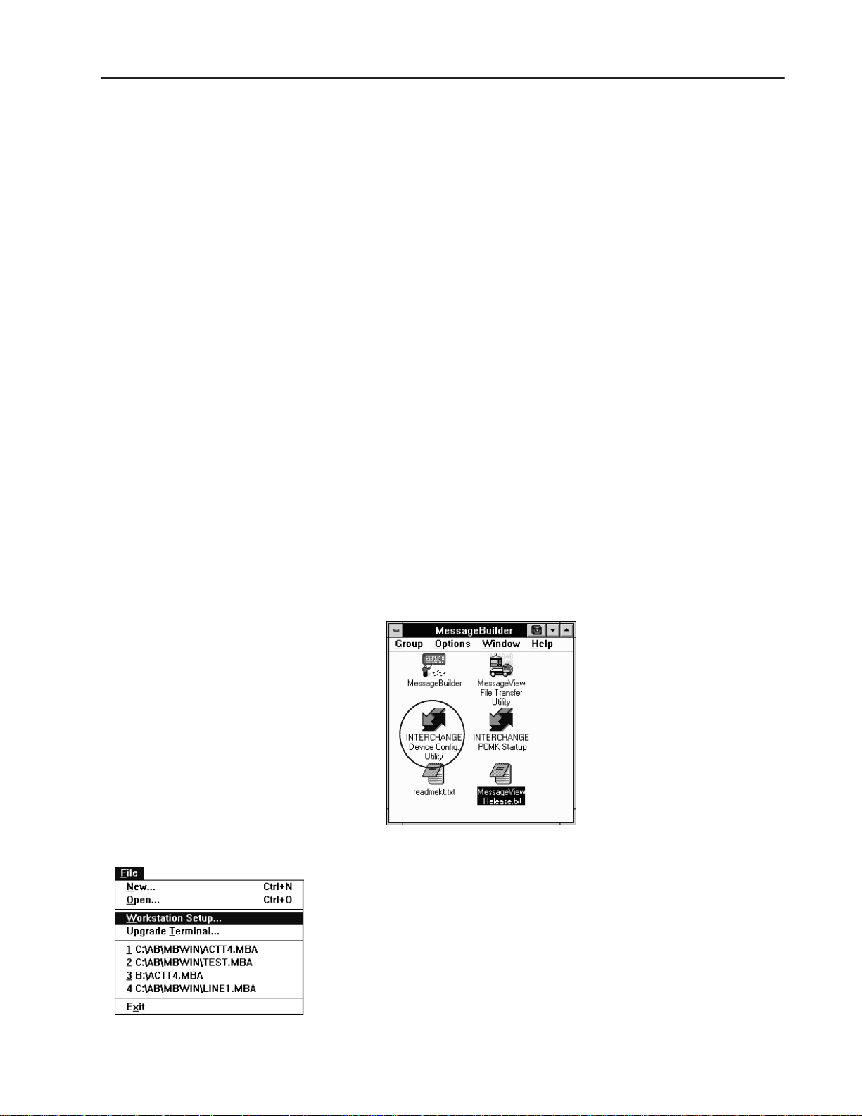
Access the INTERCHANGE Device Configuration Utility in one of
three ways:
• automatically as the final step in the MessageBuilder installation.
• as a separate icon in the MessageBuilder Group icon
Note: If Interchange was installed via another programming
software, such as AB PanelBuilder, the Interchange icon will be
found in that software’s group.
• through the Workstation Setup command in the MessageBuilder
File menu.
Publication 2706-817
Page 25
2–8 Installing MessageBuilder Software
To select and configure an INTERCHANGE driver on your
computer:
1. Double-click the utility icon in the MessageBuilder group icon, or
choose W
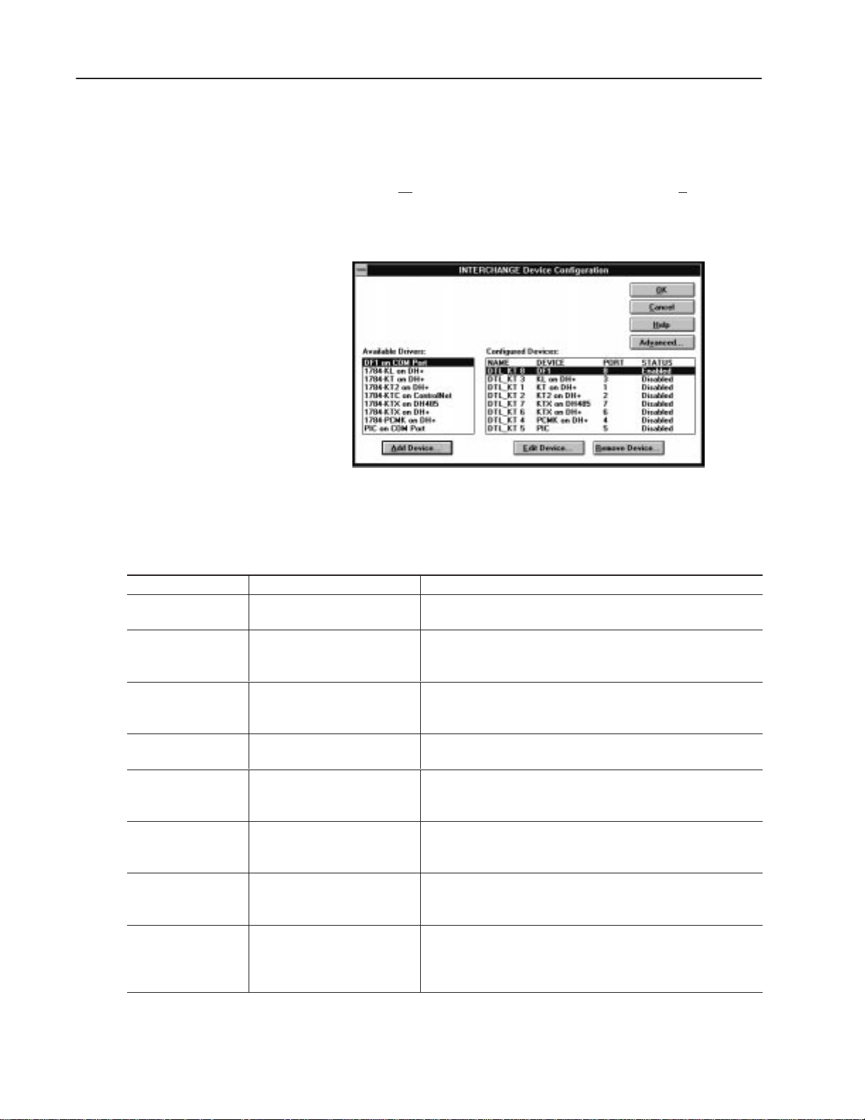
Note: At the end of the MessageBuilder installation procedure,
the INTERCHANGE Device Configuration dialog opens
automatically.
Configured Devices
orkstation Setup from the MessageBuilder File menu.
NAME
DEVICE
PORT
STATUS
Refers to driver name
Refers to selected driver
Refers to unique number assigned to
INTERCHANGE driver
Shows whether driver is enabled or
disabled
DF1 on COM Port
1784-KL on DH+ ➀
1784-KT or 1784-KT2
on DH+ ➀
1784-KTC on
ControlNet ➀
1784-KTX on DH485
➀
1784-KTX on DH+ ➀
1784-PCMK on DH+
➀
PIC on COM Port ➀
➀
Not used by MessageBuilder Software.
2. Select a driver from the Available Drivers: list. The selection
depends on the type of MessageView terminal and the
communication card installed in your computer.
Select: For MessageView Terminal: To:
2706-M1D1, -M1N1, -M1F1;
2706-M1D, -M1N, -M1F.
Transfer applications between the RS-232 port of a MessageView
terminal and a computer using DF1 (RS-232) communications.
Transfer applications between a computer on the DH+ link using a
1784-KL communications card and the Remote I/O port of a
MessageView Terminal on a Remote I/O network.
Transfer applications between a computer on the DH+ link using a
1784-KT/B or -KT2 communications card and the Remote I/O port of a
MessageView Terminal on a Remote I/O network.
Transfer applications between a computer on the DH-485 network
using a 1784-KTX communications card and the DH-485 port of a
MessageView Terminal.
Transfer applications between a computer on the DH+ link using a
1784-KTX communications card and the Remote I/O port of a
MessageView Terminal on a Remote I/O network.
Transfer applications between a computer on the DH+ link using a
1784-PCMK communications card and the Remote I/O port of a
MessageView Terminal on a Remote I/O network.
Transfer applications between a computer on the DH-485 network and
the DH-485 port of a MessageView terminal using a 1747-PIC
interface converter, or between a computer and the RS-232 port of a
MessageView terminal.
Publication 2706-817
Page 26
2–9Installing MessageBuilder Software
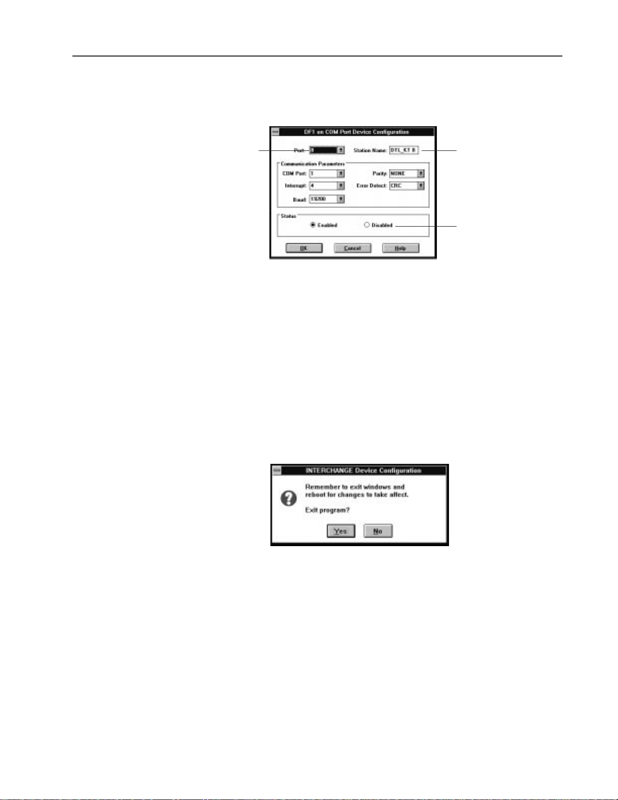
3. Select the Add Device button to add and open the configuration
dialog for the selected driver.
For example, if you select DF1 on COM Port this dialog opens:
Unique number assigned to
(This is not the computer’s COM port.)
DF1 parameters must be set to:
Baud:
Parity:
Error Detect:
Typical:
COM Port = 1 and Interrupt = 4, or
COM Port = 2 and Interrupt = 3
19200
None
CRC
INTERCHANGE driver
Default Driver Name
(can be edited)
Disables driver configuration
without removing it from
Configured Drivers list.
Note: Consult your personal computer’s user manual for COM
Port Interrupt settings.
4. Edit parameters and select OK when done.
The parameters are specific to the communications card installed
in your computer, or to the type of connection you will be using
to transfer files.
The configured driver appears under the Configured Devices: list
in the Driver Configuration dialog.
Important: Do not configure more than one driver for the same
communication port.
5. Reboot your computer to load the driver and its configuration.
Important: You must reboot your computer any time you add or
remove a driver or change configuration parameters of a
driver.
Exiting Windows and re-entering will not load the
driver.
Publication 2706-817
Page 27
2–10 Installing MessageBuilder Software
To configure an existing INTERCHANGE driver:
1. Select the driver from the Configured Devices: list.
2. Select the Edit Device button to open the configuration dialog for
the selected driver.
3. Edit parameters and select OK when done.
4. Reboot your computer to load the driver and its configuration.
To remove a current driver:
1. Select a driver from the Configured Devices: list.
2. Select the Remove Device button.
3. A dialog asks for confirmation of the removal. Choose OK.
4. Reboot your computer to unload the driver.
To specify advanced parameters for drivers:
1. Select the Advanced button from the INTERCHANGE Device
Configuration dialog.
2. Modify the settings as needed. See below.
3. Select the OK button to save the settings
Or select the Cancel button to return to the Configuration menu
without changing the parameters.
Publication 2706-817
Page 28

2–11Installing MessageBuilder Software
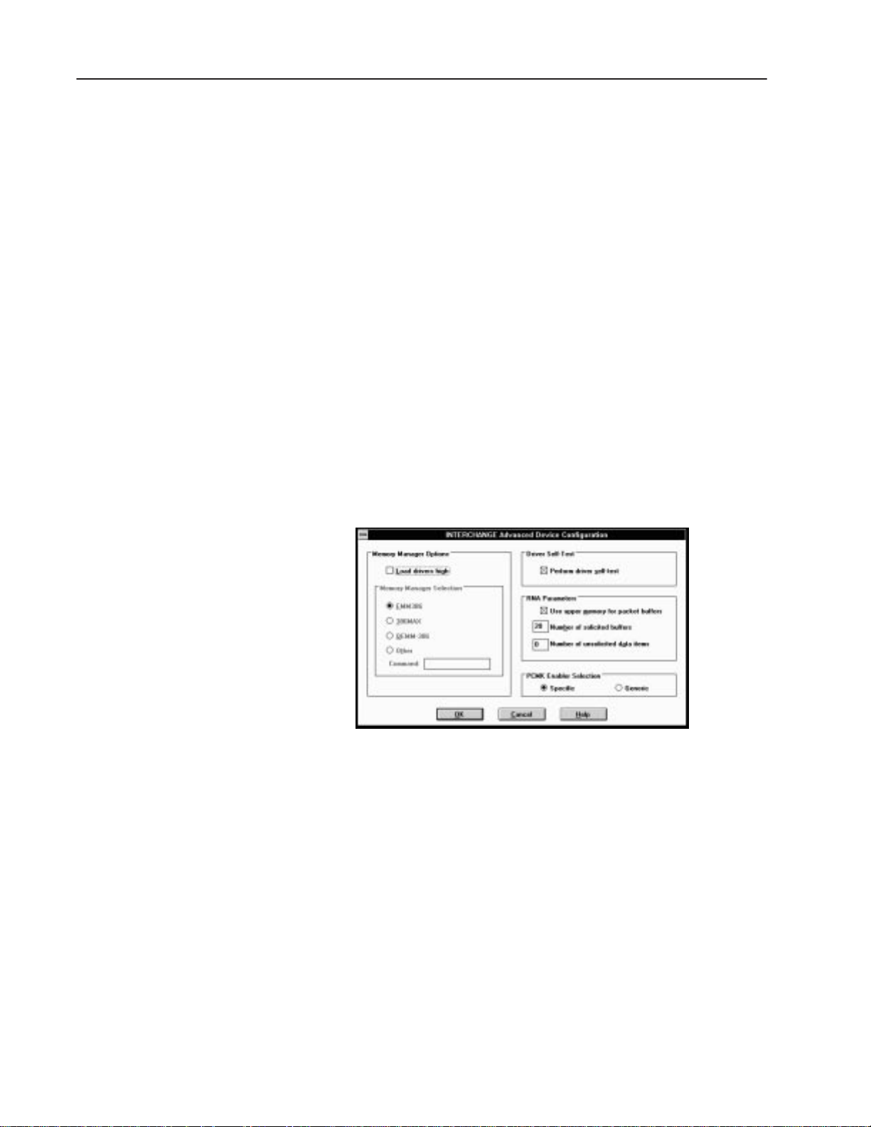
Memory Manager Options
Load drivers high when enabled (checked) loads INTERCHANGE
drivers (executables) into high memory. Drivers are not loaded until
you reboot the computer. If this option is disabled, drivers are loaded
into the base 640K memory.
MessageBuilder recommends: Either enabled or disabled.
Memory Manager Selection allows you to specify the memory
manager in use on your system. Select one of the radio buttons.
MessageBuilder recommends: EMM386.
Driver Self-Test
When enabled this option requires KT devices to run self-diagnostics
before loading driver configuration.
MessageBuilder recommends: Perform the tests.
RNA Parameters
Use upper memory for packet buffers when enabled places packet
buffer space in upper MS-DOS memory.
MessageBuilder recommends: Use upper memory.
Number of solicited buffers allocates the number of packet buffers
(1 to 200). Each buffer uses 300 bytes of memory. The default is 20.
MessageBuilder recommends: 20 buffers.
Number of unsolicited data items allocates space for unsolicited
messages (0 to 200).
MessageBuilder recommends: 0 data items, which allocates no
space.
PCMK Enabler Selection
Specifies the Enabler to use for the 1784-PCMK on the DH+ Device
Driver.
Specific Enabler uses PCMKINIT or RSIPCMK. This Enabler
requires you to enter the socket number containing the card in the
driver dialog. The INTERCHANGE socket numbers are (0 to 7). In
Windows 95, the sockets are numbered (0 to 8).
Generic Enabler uses PCENABLE. This Enabler requires that you
enter a Memory address and IRQ (Interrupt).
MessageBuilder recommends: (Ignores).
Publication 2706-817
Page 29

2–12 Installing MessageBuilder Software
Troubleshooting the Installation Procedure
Possible difficulties with installation
• If you used the default installation procedure, the Path in your
AUTOEXEC.BAT file now includes the \AB\BIN and
\RSI\IC\BIN directories. In Windows 3.1x the AUTOEXEC.BAT
file also includes SHARE.EXE. If you edit this file yourself,
MessageBuilder software requires these modifications.
• If the computer has Windows for Workgroups installed, it has a
virtual device driver (VxD) called VSHARE.386. If Windows for
Workgroups uses this share driver, remove the SHARE.EXE file
from the AUTOEXEC.BAT file. The Windows for Workgroups
manual has details on using VSHARE.386.
Note: Windows 95 does not need the SHARE.EXE file. It has its
own virtual device driver installed.
Possible difficulties with INTERCHANGE drivers
The INTERCHANGE drivers may cause conflicts with other drivers
sharing common interrupts or memory areas in the system. Here are
some problems that may occur and what to do about them.
• If you are using a special Windows video driver, try using the
standard Windows VGA driver; you may also have to edit the
EMM386 line in the CONFIG.SYS file to remove specific
memory exclusions added by the special video driver.
Exit Windows and run ABICSTOP (see below). If ABICSTOP is
not successful, comment out the ABICRUN line in the
AUTOEXEC.BAT file and reboot, then run ABICSTOP again.
• If you are experiencing lockups when using a serial mouse in a
DOS application, try waiting several seconds for the mouse to
initialize. If mouse operation is still a problem, run ABICSTOP.
It may be necessary to create a dual boot environment to manage
conflicting drivers. Refer to the DOS user manual for information
on this.
• If you experience error messages during a system reboot, they
may indicate an incomplete or incorrect configuration of the
INTERCHANGE drivers. See Page 2–8 for instructions on
configuring the drivers.
Publication 2706-817
For more details on INTERCHANGE Software, refer to the
INTERCHANGE Software user manuals and the MessageBuilder
online release notes.
Page 30

2–13Installing MessageBuilder Software
Possible conflicts in using communication ports
If you plan to run other software on your computer that uses the
same communication ports as MessageBuilder and INTERCHANGE
Software (such as APS software), follow these steps.
1. Exit from Windows if necessary. Make sure that
INTERCHANGE is not running.
2. Type ABICSTOP at the DOS prompt. For example, type:
C:\> ABICSTOP.
3. If ABICSTOP is not successful, comment out ABICRUN in the
AUTOEXEC.BAT file:
REM CALL ABICRUN.BAT
Reboot the computer and run ABICSTOP again.
4. Run the other software.
Publication 2706-817
Page 31

Chapter 3
MessageBuilder Basics
This chapter covers the following topics:
• Windows environment
• MessageBuilder window
• Message Editor Table View
• Opening and closing menus
• Status bar and toolbars
• Message Editor Terminal View
• Dialogs
• Getting help.
Windows Environment
MessageBuilder software runs in a Microsoft Windows environment.
It uses menus, dialog boxes and tools, and follows the same
keyboard and mouse conventions used by Windows.
You should be familiar with basic Windows conventions. That is,
you should know how to use the mouse, select commands from
menus, and work with windows and dialog boxes.
If you use a mouse, here are the basic terms used:
Feature: How to use it:
Click
Double-click
Choose an item or command
Select an item or command
Drag
Position the mouse pointer on the object, area, or
field, then press and release the left button once.
Position the mouse pointer on the object, area, or
field, and click the left button twice quickly.
Click to highlight the item to be affected by the next
command, or click on a dialog box option.
Click on an tool, on a menu command, or on an item
in a dialog box or Help window.
Point to an item, press and hold the left mouse
button, and move the pointer, then release the
mouse button. Use drag to highlight a text string.
If you prefer to use the keyboard:
Action: How to do it:
Press the ALT key and type the letter underlined in
Select a command from a menu
Choose an item or command
Select an item or command Highlight an item, then press the ENTER key.
the menu name simultaneously. Then type the letter
underlined in the command name.
Use the arrow keys (or in a dialog, both the TAB and
arrow keys) to move to the item
Publication 2706-817
Page 32

3–2 MessageBuilder Basics
MessageBuilder Window
Control-menu Box
Command
Border
Mouse Pointer
Status Bar
When you start MessageBuilder software, the MessageBuilder
window opens.
Maximize Button
Title Bar Minimize Button
Menu Bar
Standard Toolbar
Menu
Arrow to
⇐⇒
Resize Window
Caps Lock
off
Num Lock
on
Scroll Lock
off
Feature:
Control-menu Box
Title Bar Drag to move a window.
Menu Bar
Standard Toolbar
Command
Status Bar
Border Drag to enlarge or shrink the window.
Mouse Pointer Use to select an item or object.
Minimize Button Click to reduce the window to an icon.
Maximize Button
How to use it:
Click to open the Control menu.
Or double-click to close the current window.
Click a name on the menu bar to open the menu and
display its commands.
Or press
ALT + X, where X is the underlined letter in
the menu name.
Click a tool to carry out a command.
Can be toggled on/off using the V
iew menu.
Click a command to choose it or to carry out its
action.
Or type the underlined letter in the command name.
Shows what the software is doing at the moment.
Can be toggled on/off using the View menu.
Click to enlarge the window to the full size of the
screen.
Publication 2706-817
Page 33

3–3MessageBuilder Basics
Here are the commands available on each menu when no application
file is open.
File menu has commands that:
• create and open application files
• configure the computer workstation for file transfer
• download new firmware to a MessageView 421 terminal.
• list the last four applications that were opened, for easy reopening
• exit MessageBuilder software.
View menu has commands that:
• toggle the Standard Toolbar on and off
• toggle the Status Bar on and off.
Application menu has commands that:
• manage projects and their devices
• upload an application file or the Historical Event Stack file from a
MessageView 421 terminal
• download the time and date to the terminal’s Real Time Clock
• allow the user to set preferences.
Help menu has commands that:
• identify the versions of MessageBuilder and AB Utilities software
and the registration serial number
• access topics in the MessageBuilder Help utility.
Four tools are active:
• New File
• Open File
• both Help tools.
Publication 2706-817
Page 34

3–4 MessageBuilder Basics
Message Editor Table View
Title Bar
Menu Bar
Standard Toolbar
Message Edit Toolbar
Attribute Controls
Message List
Status Bar
When an application is opened, the Message Editor Table View
appears. Messages are created and edited in this View, and have their
attributes set.
The Message Edit box displays the highlighted message from among
those in the Message List.
Use the standard Windows resizing arrows as needed.
Message Edit Box
Arrow to
⇐⇒
Resize Window
Vertical
Scroll Bar
Feature: How to use it:
Menu Bar
Standard Toolbar
Message Edit Toolbar Click a tool to edit messages and their variables.
Message Edit Box Edit the message highlighted in the Message List.
Attribute Controls Define attributes for the selected message.
Message List
Status Bar
Select a name on the menu bar to open a menu and
display its commands.
Click a tool to edit message text or carry out other
functions.
Toggle it on/off using the View menu.
Messages appear here as they are created.
The selected one is highlighted and appears in the
Message Edit box.
Shows what the software is doing at the moment.
Toggle it on/off using the View menu.
Note: If the application file name in the title bar has an asterisk (*),
the application has been edited but not saved to disk.
Publication 2706-817
Page 35

3–5MessageBuilder Basics
Here are the commands available on each menu when an application
file is open.
File menu has commands that:
• create, open, close and save application files
• generate reports
• configure the computer workstation for file transfer
• download new firmware to a MessageView 421 terminal
• list the last four applications that were opened, for easy reopening
• exit to the Windows desktop.
Edit menu has commands that:
• copy, cut and paste text strings; undo and restore changes in a
message
• insert, append and delete whole messages
• find, sort and renumber messages in the Message List
• replace text strings in one or many messages
• assign names to topics.
View menu has commands that:
• toggle the Standard Toolbar and the Status Bar on and off
• zoom the Terminal View in or out.
Format menu has commands that:
• specify what size the message text will be in the terminal display
• align text in the display
• display selected text in a message with Flash and Inverse Video
• insert and edit Time and Date Displays, Numeric and ASCII
Display Variables in a message
• (for MessageView 421N and 421F terminals) insert and edit
Numeric Entry variables in a message
• (for terminals whose firmware can support these variables) insert
and edit Numeric Entry and ASCII Entry variables in a message
• insert graphic symbols and ASCII characters in a message
• (for MessageView 421F terminals) enable function keys for a
message.
Publication 2706-817
Page 36

3–6 MessageBuilder Basics
Application menu has commands that:
• create tags and their attributes that will be assigned to variables
when messages are created
• manage projects and their devices
• enter a description of the application
• validate and download an application to a MessageView 421
terminal or to a DOS file
• upload an application file or the Historical Event Stack file from a
terminal
• download the time and date to the terminal’s Real Time Clock
• set up the terminal’s communications, control and status tags, and
global attributes
• assign bit triggers and date/time tags for special messages
• (for MessageView 421F terminals) set global attributes and assign
tags for all the function keys and LEDs used in the application
• allow the user to set preferences.
Window menu has commands that:
• open and arrange application windows and arrange their icons
• open the list of problems in the application (“Exceptions”) that
were identified after a Validate or Download command
• open the Terminal View and toggle it with the Table View
• list the windows currently open for easy access, with the active
one checked.
Help menu has commands that:
• access topics in the MessageBuilder Help utility.
• identify the versions of MessageBuilder and AB Utilities software
and the registration serial number
Publication 2706-817
Page 37

3–7MessageBuilder Basics
Opening and Closing Menus
Each name on the menu bar opens a menu with a set of commands.
To open a menu:
• point to a name on the menu bar and click the left mouse button
• or press ALT and the underlined letter in the menu name
simultaneously. For example, to open the File menu, press
ALT + F.
MessageBuilder menus look like this:
Note: Appendix A lists the commands on each menu and briefly
explains what each one does.
To choose a menu command:
• click the command name
• or type the underlined letter in the command name
• or use the UP and DOWN ARROW keys to choose an item; then
press
ENTER to select it.
Menu conventions are listed in this table:
Menu convention: What it means:
Greyed command name The command is not available at this time.
A check mark () before the
name
A key combination after the name
An ellipsis (...) after the command
A triangle () to the right of a
menu command
The command is active. Select the command to
inactivate the command; the check mark disappears.
Select it again to activate it.
A shortcut for the command. Use the shortcut keys if
you prefer instead of the menu command or tool.
The command opens a dialog box that contains
options that must be selected before
MessageBuilder software can carry out the
command.
The command opens a submenu.
Publication 2706-817
Page 38

3–8 MessageBuilder Basics
To close a menu:
• click the menu name or anywhere outside the menu
• or press ALT or F10 to close the menu and move back to the
workspace
• or press ESC to close the menu and remain on the menu bar.
Status Bar and Toolbars
The status bar appears at the bottom of the MessageBuilder window.
• It indicates what the software is doing at the moment.
• It explains a tool’s function when the left mouse button is pressed
down while the cursor is over a tool.
• It explains the command when a menu command is highlighted.
• It gives the status of the Caps Lock, Num Lock and Scroll Lock
keys on the keyboard.
To toggle the status bar on or off:
1. Choose V
2. Choose S
A check mark (
it is active. To turn the status bar off, choose the command again.
iew from the menu bar.
tatus Bar from the View menu.
) appears next to the Status Bar command when
Publication 2706-817
Page 39

Standard Toolbar
Message Edit Toolbar
3–9MessageBuilder Basics
Standard and Message Edit toolbars
Two toolbars are located at the top of the application window. Tools
provide easy access to commonly used commands. Instead of
opening a menu and choosing a command, simply click a tool to
carry out an action. Some tools complete the action immediately;
others open a dialog or a menu for further input.
Note: Tools on a toolbar can be accessed only with a mouse. All
toolbar commands are available on one of the menus or in the
Applications area.
Message Edit Box
To identify a tool, move the cursor arrow to the tool. Press and hold
the left mouse button while watching the status bar.
• If the tool is correct, release the mouse button.
• If the tool is not correct, move the cursor off the icon before
releasing the mouse button.
Note: Appendix B lists all the available tools and briefly explains
what each one does.
To toggle the Standard Toolbar on and off:
1. Choose V
2. Choose T
A check mark (
active. To disable the Toolbar command, choose the command again.
iew from the menu bar.
oolbar from the View menu.
) appears next to the Toolbar command when it is
Note: The Message Edit toolbar cannot be turned off.
Publication 2706-817
Page 40

3–10 MessageBuilder Basics
MessageBuilder defaults
MessageBuilder software keeps the most recent Standard Toolbar
and Status Bar settings as its default settings. Default settings are
used:
• the next time MessageBuilder software is opened
• when a new application is created.
Message Editor Terminal View
Message Edit Box in the Table View.
Display area in the Terminal View.
In addition, the P
offers other selectable options. See Page 7–14.
The Terminal View displays messages approximately as they will
appear on a MessageView 421 terminal. This view represents the
front face of the type of terminal the application is designed for.
The Message Edit box on the Table View is active while the
Terminal View is displayed. If the Terminal View is the active
window, as a message is edited the changes appear in the Terminal
View display.
references command on the Application menu
Publication 2706-817
The Terminal View may be enlarged or reduced using the Zoom
tools or the Zoom command on the View menu. See Page 7–17.
Note: The Terminal View, like the MessageView terminal, can
display only:
21 characters in Quarter text size
10 characters in Half text size
7 characters in Full text size.
If the message is longer than the Terminal View can display, scroll
through the message in the Message Edit box to see the remainder of
the message. When the Terminal View is the active window, its
display will follow the insertion point in the Message Edit box. That
is, it will scroll through the message up to the cursor point.
Page 41

3–11MessageBuilder Basics
Dialogs
Tab
Check Box
Radio Button
MessageBuilder software uses dialogs to request information it needs
to carry out a command. After you supply the requested information,
select a command button to confirm or cancel the command.
Dialogs also display additional information and warnings, or explain
why a requested task could not be accomplished.
An ellipsis (...) after a dialog command means another dialog will
open when you choose that command.
Some dialogs provide different sets of options, each on a separate
tab. Select the tab to work with a specific set of options.
A sample dialog:
List Box
Spin Control
Command Button
To move around a dialog:
• move the mouse pointer to a field and click the left mouse button
• or press TAB to move forward through fields and SHIFT +TAB to
move backward through fields. Use the arrow keys to select a
radio button
• or press the ALT key and the underlined letter of a field name
simultaneously. For example, to move to the R
Number check box, press
ALT+R.
eturn Message
Publication 2706-817
Page 42

3–12 MessageBuilder Basics
Features of dialogs
Command Buttons
Short rectangles with text explaining their function. Select a
command button to invoke the command.
Text Boxes
Long rectangles with instructions about what should be entered in
them. Sometimes these boxes contain a default value or text,
sometimes they are empty. The mouse pointer changes to an
I-beam
when it is on a text box.
• To add text, place the cursor point where the new text goes and
start typing.
• To delete text, highlight it and press the DELETE or BACKSPACE
key.
• To replace some or all text, highlight it and type the new text.
List Boxes
Boxes with a down-arrow at the right. To configure an item within a
List Box:
• Click on the down arrow to the right of a list box to display its
list, then click on an item to select that option.
• Or move the highlight to a list box and press ALT + the
down-arrow key
arrow key to select an option.
If there are more items than can fit in the list, a scroll bar appears.
Some list boxes let you use the mouse to select multiple items. Click
on the first item, press and hold the
item. Or click the first item and drag the pointer to the last item. To
deselect a range, click the first item on the list.
Drop-Down Text Boxes
Text boxes with a down-arrow at the right, separated from the text
box. To configure an item within a Drop-Down Text Box:
to display the list. Then use the up or down
SHIFT key, then click the last
• Click on the down arrow to the right of a list box to display its
list, then click on an item to select that option.
• Or move the highlight to a list box and press ALT + ↓ (the
down-arrow key)
arrow key to select an option.
to display the list, then use the up or down
• Or highlight existing text in the box and type the appropriate
name or number.
Publication 2706-817
Page 43

3–13MessageBuilder Basics
Check Boxes
Square boxes that may contain an X or ✓. Check boxes are used to
select or clear an option. An X or ✓ in the box means the option is
selected. A blank (cleared) box means the option is not selected.
• Click on a check box to select or deselect the option.
• Or select a check box and press the Spacebar to toggle it.
Radio Buttons
Circles that function as a group. One of the group has a solid dot in
the middle (it is selected), and all the others are blank. Choose a
button in the group to select that option and clear all other options.
• Click on a radio button to select it.
• Or select a group of radio buttons and press the up or down arrow
key to toggle them.
Spin Controls
Small boxes with up/down arrows at the right. To configure an item
within a Spin Control box:
• Click the up or the down arrow until the required number appears
in the box.
• Or highlight the text and type the number.
Tabs and Dialog Buttons
Some dialog boxes have tabs which open to give new sets of options.
Others have buttons that open a Tag Form or other dialog. Select a
tab or button to display a new set of options.
Publication 2706-817
Page 44

3–14 MessageBuilder Basics
Getting Help
MessageBuilder software has both context-sensitive and online help.
Help may be invoked by any of the following commands.
• Click the Help Question tool and the mouse arrow changes to a
question mark. Click the question mark on an item for
context-sensitive help.
• Click the Help Contents tool to display an index to Help topics.
• Choose a command from the Help menu. The Contents command
brings up the same index as the Help Contents tool.
• Select a dialog’s Help button to get help about the its topic.
• Press the F1 key at any time to get context-sensitive help.
Using Help
This is a very brief overview of the Help features. For further
information on using Help, select H
Microsoft Windows manual.
All of the methods of finding information on a topic produce the
same textual information. Choose the method most convenient for
you among those listed here.
Helpful hints:
ow To Use Help or see the
• If a term is underlined, you may select it to bring up a new screen
defining or describing that subject.
• If scroll bars appear, you may use them to see more items on the
list or more information on the subject.
• To return to a previous screen, use either the Back button (which
steps through each screen you have called up) or the Hist
button (which lists all the screens you have called up, so you can
double-click on the one you want to return to).
ory
• To see text on a related subject, use the Previous (<<) or Next
>) button.
(>
Publication 2706-817
Page 45

Contents
3–15MessageBuilder Basics
The Help C
ontents screen is illustrated above.
1. Double-click a subject on this index to bring up a new screen,
which contains a subindex of subjects on the topic.
2. Then double-click on a subject in the subindex, until you reach
text describing the topic you want information on.
earch
S
The S
earch button at the top of the Contents screen brings up a
dialog with an alphabetical list of all the Help headings.
To locate a topic:
• use the scroll bar
• type one or a few letters to display the part of the alphabet that
contains the subject you are interested in.
When you see the name of a Help subject that you want:
1. Highlight the name or type it in the W
2. Select the S
3. Select the G
how Topics button.
o To button.
A screen appears with text describing or explaining the selected
topic.
ord box.
Publication 2706-817
Page 46

3–16 MessageBuilder Basics
Help Topics:Contents
The He
lp Topics button at the top of the Help Contents screen brings
up a tabbed dialog. The first tab is Contents.
In this screen, if the button next to a subject is:
• a book, double-click on it to display a list of subtopics
• a question mark, double-click on it to bring up text on the subject.
He
lp Topics: Index
The Index tab displays a dialog with an alphabetical list of all the
Help headings.
Publication 2706-817
Page 47

3–17MessageBuilder Basics
To locate a topic:
• use the scroll bar
• type one or a few letters in the Type box to display the part of the
alphabet that contains the subject you are interested in.
When you see the name of the subject that you want help with:
1. Highlight the name in the C
lick box, or type it in the Type box.
2. Select the D
isplay button.
A screen appears with text describing or explaining the selected
topic.
Help Topics: Find+
The Find+ tab displays a dialog you may use to find every instance
of a word that appears in Help text.
To locate all instances of a term anywhere in the Help files:
1. Type part of a word or a whole word in the E
nter search text box.
If you want to be more specific, type several words. Find+ locates
exactly what you type, provided it is in the Help text.
2. If it will narrow the search, select one or more of the check boxes
below the E
3. Select the F
nter box.
ind button. The Select a Topic box fills with all the
Help topics that contain the term. The topic that has the most
examples of the term is listed first and highlighted.
4. The first instance of the term in the highlighted topic appears in
the To
pic text box. To move from one instance of the term to
another:
• use the Term up/down arrows at the bottom of the screen
• use the scroll bars if they are present to display more of the text.
Publication 2706-817
Page 48

3–18 MessageBuilder Basics
5. To select another topic, do one of the following:
• click on a topic to highlight it
• use the Topic up/down arrows at the bottom of the screen to move
the highlight
• use the scroll bars if they are present to display more of the list.
6. When you find a subject about which you want to read more,
click the D
isplay button. A full screen appears with the Help text.
About MessageBuilder
If you must call Allen–Bradley for assistance, you will have to
provide the release date and version number of MessageBuilder
software. Choose A
this dialog:
bout MessageBuilder from the Help menu to get
User name
Company name
It gives you:
• the version number and release date of MessageBuilder software
• the version number of the Allen-Bradley Utilities software
• the serial number of this particular software package.
Publication 2706-817
Page 49

Chapter
Planning an Application
This chapter covers the following topics:
• Design checklist
• Safety considerations
• Applications and projects
• Messages
• Triggering a message
• Controlling devices
• Slaving
• Slave Device
• Historical Event Stack
• Function keys
• Function key types
• LED indicators
• Handshaking
• Tags
• Data types
• Address worksheet
• Defining tags
• Scaling data display variables
• Scaling data entry variables
• Precision and rounding.
4
Design Checklist
Before creating an application, check the following:
Plan the application: what is it supposed to do, and how?
Outline the documentation the operator will work from.
Finish it after the application is completed.
Consider safety requirements.
Review data types and data formats.
Fill in the Address Worksheet (Appendix H).
Review communications (Chapter 5).
Publication 2706-817
Page 50

4–2 Planning an Application
Safety Considerations
The application designer must make sure that an application cannot
be used in an unsafe manner. Failsafes must be built into each
application.
ATTENTION: Do not configure Function Keys as
emergency stops or other controls critical for safe
!
Refer to “Safety Guidelines for the Application, Installation and
Maintenance of Solid State Controls” (Publication SGI-1.1).
Communications interruptions
The MessageView 421 terminal relies on communications with the
logic controller or ASCII Triggering device.
operation. Use separate hard-wired operator interface
devices.
• Communications are interrupted within the terminal when it:
– is in the Front Panel Editor mode
– is receiving an application download from a personal
computer
– has a major fault
– loses power
– detects that the Remote I/O link has failed.
The logic controller considers the terminal as a faulted I/O rack
when it does not communicate. The controller must be programmed
to cope with this situation. Specifically, it must:
• return any machine or process to a safe state
• monitor the rack fault bit associated with the MessageView
terminal’s assigned rack.
Refer to the controller’s user manual.
Publication 2706-817
Page 51

4–3Planning an Application
Applications and Projects
Here are the steps needed to create an application:
1. The designer should document the application carefully. This
documentation should include the purpose of the application,
what information the operator will need to make good decisions,
and what choices the operator will have to make. The designer
and operator should discuss this document together before the
application is run.
ATTENTION: Documentation is often neglected, but
is very important. The operator can make better
!
2. The designer creates an application, the basic design unit of
MessageBuilder software. It is designed to be loaded in a specific
type of MessageView terminal, run using a specific type of
controller, and direct a specific operation. It includes:
decisions if the designer explains what is going on.
– messages, with their attributes, triggers, embedded graphics,
and embedded display and entry variables
– configuration parameters for communications port(s) of a
specific MessageV iew terminal
– global attributes that apply to all messages in the application
– tags, which are named references to data addresses in a
specific logic controller (ASCII Triggering devices use the
tags as memory references)
– function keys and LEDs (MessageView 421F terminals only).
3. The designer associates the application with a project, which is
assigned or created when an application is created. A project can
support more than one application, provided that all of them are
designed for the same type of terminal and the same type of logic
controller. It links the application(s) to:
– the tag database
– the specific devices – the MessageView terminal and the PLC,
SLC or ASCII Triggering device – that the application will
interact with.
4. Values associated with variables are stored in controller memory
addresses, and are referenced by the application via named tags.
The designer usually enters all the tags in the Tag Editor Table
View before creating any messages. Tags may also be edited later
when they are assigned to their variables.
Publication 2706-817
Page 52

4–4 Planning an Application
5. The application designer can validate an application at any time,
using the V
Incompatibilities are caught during validation. See Page 11–2.
Note: An application is automatically validated by
MessageBuilder software before it is downloaded to a terminal.
6. The designer or operator can monitor how the application is
running. Messages that have their HE Stack attribute set are
logged into the Historical Event Stack file each time they are
triggered. These logged messages include the value of their
display variables at the instant of triggering, and the current date
and time. The HE Stack file is uploaded to the computer on
request.
alidate command on the Application menu.
Messages
A MessageView terminal has memory reserved for an application
with up to 4096 standard messages. Messages are triggered
individually by the Logic Controller or ASCII Triggering device as
required by the interaction between:
• the MessageBuilder application, and
• feedback from the machinery to the Logic Controller or ASCII
Triggering Device.
The content of a message is determined by:
• the MessageBuilder application
• information transferred between the MessageView terminal and
its controller.
Each message has a unique number, which is used to identify it in the
application. Numbers in the range:
• 1 to 9900 are used for application messages
• 9901 to 9999 are reserved for Special Messages
• greater than 9999 are not supported by the MessageView
terminal.
A message’s number is its value trigger. A message may also have a
bit trigger assigned to it. To trigger a specific message in the terminal
display, assert its corresponding bit or value trigger at the proper
location in controller memory. See the section on Triggering on
Page 4–9.
Publication 2706-817
Page 53

A message may be up to 100 characters long, and can include any
combination of text, graphics, and variables. It can have:
• up to one date variable
• up to one time variable
• up to 10 entry or display data variables in any combination,
provided the total message length is 100 characters or fewer
• up to 50 graphics symbols, provided the total message length is
100 characters or fewer.
Variable and Graphic display characteristics in the Message
Editor
Message Component Table View Terminal View
Time Sample Time Sample Time
Date Sample Date Sample Date
Numeric Data Entry Placeholder (^^^) Placeholder (^^^)
Numeric Data Display Placeholder (###) Placeholder (###)
ASCII Data Entry Placeholder (EEE) Placeholder (EEE)
ASCII Data Display Placeholder (AAA) Placeholder (AAA)
ASCII Character Placeholder (~) Placeholder (~)
Graphics Placeholder (GR) Actual graphics symbol
Message text Alphanumeric Alphanumeric
4–5Planning an Application
Special Messages
The MessageView terminal supports a predefined set of Special
Messages. Message numbers 9901 to 9999 are reserved for Special
Messages.
Special Messages are triggered just like any other message while an
application is running. When triggered, they are typically not
displayed by the terminal, but acted upon.
Special Messages:
• cannot be edited, although bit triggers may be assigned to them
• are not displayed in the Message Editor Table View
• are not displayed in the Message Editor Terminal View
• cannot be chained to another message
• are not logged into the Historical Event stack.
The Special Messages dialog is found on Page 7–54.
Publication 2706-817
Page 54

4–6 Planning an Application
This table gives the current Special Messages.
Message
Number
Message Description ASCII Triggering Device Requirements
9901 Clear Display
Clear Value
9902
Triggered Message
Queue
9903
Reset MessageView
Terminal
9904 Display Test
9905
Set Clock – Time –
Date
Clears all active display messages.
The display/slave buffers and Slave Devices
are not cleared.
Clears the Value Triggered Message Queue
and any display/slave buffers.
Aborts all terminal functions in progress.
Resets the terminal, which then goes through
its Power On Self Test (POST).
Tests every pixel in the terminal display.
During the test, the terminal suspends all
message activity. When the test is completed
the terminal resumes normal Run Mode
operation.
Sets or updates the Real Time Clock in the
terminal from addresses in the logic
controller. Valid only if the tags are defined in
the Special Messages dialog.
Use the [Ctrl-T] command:
to terminal: [Ctrl-T]9901\ MV Address [CR]
Use the [Ctrl-T] command:
to terminal: [Ctrl-T]9902\ MV Address [CR]
Use the [Ctrl-T] command:
to terminal: [Ctrl-T]9903\ MV Address [CR]
Use the [Ctrl-T] command:
to terminal: [Ctrl-T]9904\ MV Address [CR]
Use six [Ctrl-V] commands: year, month, day, hour,
minute, second:
to terminal: [Ctrl-T]9905\ MV Addr [CR]
to terminal: [Ctrl-V]Year Value\ 1\ MV Addr [CR]
[Ctrl-V]Month Value\ 2\ MV Addr [CR]
[Ctrl-V]Day Value\ 3\ MV Addr [CR]
[Ctrl-V]Hour Value\ 4\ MV Addr [CR]
[Ctrl-V]Minute Value\ 5\ MV Addr [CR]
[Ctrl-V]Second Value\ 6\ MV Addr [CR]
9906
Get Real Time Clock
Time/Date
9907 Battery Test
9908
Display Brightness
Adjustment
Use six [Ctrl-I] responses: year, month, day, hour,
minute, second:
Sends the terminal Real Time Clock time and
date to addresses in the logic controller.
Valid only if the tags are defined in the
Special Messages dialog.
to terminal: [Ctrl-T]9906\MV Addr [CR]
from terminal: [Ctrl-I]9906\ Year Value\ 1 [CR]
[Ctrl-I]9906\ Month Value\ 2 [CR]
[Ctrl-I]9906\ Day Value\ 3 [CR]
[Ctrl-I]9906\ Hour Value\ 4 [CR]
[Ctrl-I]9906\ Minute Value\ 5 [CR]
[Ctrl-I]9906\ Second Value\ 6 [CR]
Tests the battery for sufficient power. If the
Battery Test passes, a 1 is sent to the battery
status bit. If the Battery Test fails, a 0 is sent.
Valid only if the tag is defined in the Special
Use the [Ctrl-I] response:
to terminal: [Ctrl-T]9907\ MV Addr [CR]
from terminal: [Ctrl-I]9907\ 1 or 0\ 1 [CR]
Messages dialog.
Adjusts the brightness of the display
according to the value input in the Special
Message.
1
If an incorrect value is input for the brightness
Use the [Ctrl-V] command:
to terminal: [Ctrl-T]9905\ MV Addr [CR]
to terminal: [Ctrl-V]0 to 7\ 1\ MV Addr [CR]
level, the terminal will ignore the command.
Valid only if the tag is defined in the Special
Messages dialog.
Publication 2706-817
Page 55

4–7Planning an Application
1
This table shows the brightness level corresponding to each value in
Special Message 9908’s Ctrl-V command:
Value 0 1 2 3 4 5 6 7
Levels 12% 25% 38% 50% 60% 75% 87% 100%
Controlling Devices
A MessageView terminal can accept commands from one of these
two types of controlling devices:
• a logic controller such as an Allen-Bradley PLC or SLC
A logic controller communicates with a MessageView terminal
through the Remote I/O port on the daughterboard card.
Terminals with daughterboard cards are Catalog Nos.
2706-M1D1, -M1N1 and -M1F1.
• an ASCII Triggering device, such as an Allen-Bradley computer
product or SLC BASIC Module. See Page 5–7 for a list.
An ASCII Triggering device communicates through the RS-232
port on the main board of the terminal. It is used with terminals
that do not have daughterboard cards: Catalog Nos. 2706-M1D,
-M1N and -M1F.
MessageView features supported by a controlling device
A MessageView terminal can support the following features when
controlled by either type of device:
• displaying triggered messages with or without embedded
variables
• queuing messages
• chaining messages
• supporting Special Messages
• supporting hidden messages to be sent to the Historic Event Stack
when triggered
• displaying messages with Numeric Entry variables embedded, in
421N and 421F terminals
• implementing Handshaking for latched function keys, in 421F
terminals
• scaling Numeric Display and Numeric Entry variables
• returning Message Numbers to the controlling device
• displaying Startup and Background messages
• supporting Debug Mode
• supporting Simulate Mode
Publication 2706-817
Page 56

4–8 Planning an Application
MessageView features supported by a logic controller
A MessageView terminal can support the following additional
features when controlled by a PLC or other logic controller:
• supporting Handshaking for numeric entry and ACK messages as
well as for latched function keys
• supporting bit triggering
• supporting Startup and Background messages that contain
embedded display variables
• sending Preset or Last values for variables to the controller
ASCII Triggering Device limitations:
• If the ASCII network has more than one device, the terminal
operator must not send data (such as Entry variables embedded in
a message) from the MessageView terminal to the ASCII
Triggering device. This could cause data collisions. Consider this
when creating an application for such a network.
Data is sent from a terminal when:
– the ACK key is pressed (all terminals)
– numeric keys are used (421N and 421F terminals)
– an enabled Function key is pressed (421F terminals)
• The MessageView terminal supports an output buffer to process
outgoing data responses. The buffer is designed to handle at least
two of the largest responses (such as 20 Ctrl-I responses or 2
messages that contain the maximum of 10 Entry Variables).
If the output buffer becomes full (for instance, if someone
repeatedly presses a Momentary Function Key before the data can
be sent), any new outgoing data is lost until the output buffer is
available again.
• ASCII Trigger applications require a value trigger tag name to be
defined. See Page 10–21. Only the tag name is used; the node
address and node name may be left blank. The tag name is used
internally by the MessageView terminal as a reference.
Communication setup
In MessageBuilder software, a logic controller is specified by its
PLC/SLC/Scanner type. An ASCII Triggering device is a single
device that does not require a device type.
Publication 2706-817
Page 57

4–9Planning an Application
Triggering a Message
All messages, including Special Messages, must be triggered to be
displayed on, or used by, the MessageView terminal. A message may
be defined as only value trigger, or both value trigger and bit trigger.
• Value trigger is acquired from either a logic controller or from an
ASCII Triggering Device.
• Bit trigger is acquired only from a logic controller, using Remote
I/O communication.
Note: In time-critical or priority type applications, bit triggering is
recommended if available.
Important: An ASCII Triggering device cannot use Bit Triggering.
Value triggering
This method uses the message number as a trigger. Each message in
an application has its own unique number, so there are as many value
triggers in the application as there are messages.
When the terminal receives the message number value trigger, it
• displays the message if its assigned lines are free and its Hidden
attribute is disabled
• queues the message if its lines are occupied, the Hidden attribute
is disabled and the Message Queue is enabled
• logs the message into the HE Stack whether is is displayed or not,
if its HE Stack attribute is enabled
• ignores the message if the line(s) are occupied and the HE Stack
attribute and the Message Queue are disabled.
• slaves the message whether displayed by the master device or not
if the slave attribute is enabled.
Some messages may be triggered but are not displayed:
• messages with the Hidden attribute set
• Special Messages.
Note: Any message that has its HE Stack or slave attribute set, is
sent to the Historic Event Stack or the slave device when it is
triggered. The message does not have to be displayed.
Publication 2706-817
Page 58

4–10 Planning an Application
From a logic controller using Remote I/O
The MessageView terminal supports a Value Trigger tag in the PLC
or other logic controller. When a message is to be triggered, the logic
controller writes the message number to this tag address.
Only one message may be value-triggered at a time. The terminal
scans the Value Trigger tag address at regular intervals. A triggered
message number must remain stable in the Value Trigger tag address
for a minimum of 100 milliseconds, to allow for the terminal scan
times.
The message is not triggered again until the value in the Value
Trigger tag address is changed to a different number and then
changed back. Thus the ladder logic application designer may use a
message number of 0 (zero) to change the Value Trigger tag address
without triggering a message.
From an ASCII Triggering Device using RS-232
The MessageView terminal supports the triggering of messages
using the Value Trigger method. The format of this method is:
[Ctrl-T]Message Number\MessageView Address[CR]
• [Ctrl-T] is the control code for a command to the terminal
• Message Number is the value trigger for the message
• MessageView Address is the node in the network where the
terminal is located
• [CR] is the carriage return that ends a packet.
Note: The delimiter in ASCII triggering packets uses the backslash \.
In order to trigger a message, the ASCII Triggering Device transmits
a [Ctrl-T] packet sequence. When the terminal receives this packet, it
displays or queues the message.
Note: A MessageView terminal in an ASCII network that has an
address from 1 to 126 will respond to messages addressed to it, and
also to messages addressed to 127. A terminal with an address of 127
will respond to messages addressed to 127 only.
Publication 2706-817
Page 59

4–11Planning an Application
The Message Queue
Queuing is important in situations where multiple message triggers
are likely to occur. Value triggered messages that are triggered but
cannot be displayed at once are stored in the terminal’s Message
Queue if the Queue is enabled.
Note: A bit–triggered message is not queued. The bit remains set
until the controller resets it.
The MessageView terminal supports two fixed Message Queue
lengths, set in the Terminal Setup Advanced dialog. See Page 10–13.
The length may be:
• 64 messages deep (the Queue is enabled)
• 1 message deep (in effect, the Queue is disabled)
The MessageView terminal processes messages according to the
following criteria:
• A triggered message is displayed at once if possible.
• If the specified line for a value–triggered message is not free, it is
placed at the bottom of the Message Queue Stack.
• Messages are processed from the Queue Stack in a top-to-bottom
First In, First Out (FIFO) priority.
• The topmost message is displayed when its assigned display line
is available. The terminal continues to queue additional triggered
messages while it waits to display the topmost message.
Note: Messages in the Queue are not displayed until they reach
the top of the Queue, even if their line is available.
• If the Queue reaches Full status, the next message that is queued
will be entered at the top of the Queue, overwriting a pre–existing
queued message.
Note: The Message Queue is not cleared when the terminal operator
enters the Front Panel Editor (FPE). When the operator closes the
FPE, Run mode resumes and the queued messages are displayed as if
there was no interruption.
The Message Queue is cleared if:
• the terminal has processed all queued messages
• the terminal is reset
• the controller triggers a Clear Queue (9902) Special Message
• the controller triggers a Terminal Reset (9903) Special Message.
Publication 2706-817
Page 60

4–12 Planning an Application
Bit triggering
This method uses bits within a designated word of memory, the Bit
Trigger tag address, to trigger messages. The Bit Trigger tag is
defined in the Terminal Setup dialog (see Page 10–21). Starting with
this tag address, you may reserve up to 64 words (1024 bits) in
sequence for all the bit triggers in the application.
If the system uses Remote I/O to transfer data, the maximum number
of bit triggers may be reduced.
RIO Method Rack Size
Discrete I/O
Discrete I/O
Discrete I/O
Discrete I/O Full 128
Block Transfer
1
/
4
1
/
2
3
/
4
1
/4 to Full 1024
Maximum # of Bit
Triggers
32
64
96
When the Bit Trigger attribute is enabled for a message, its bit is also
assigned. Only one message may be assigned to a particular bit
address.
When a message is to be bit triggered, the logic controller writes a 1
to a specific bit at the Bit Trigger tag address.
• When the logic controller resets the bit to 0, the corresponding
message is not displayed.
• When the logic controller sets the bit to 1, the terminal displays
the message if its assigned display line is available.
Important: If its line is not available and the bit remains set
(1), the terminal will display the message when
the corresponding line becomes available.
Publication 2706-817
If the bit is reset to 0 before the line is available, the terminal will
ignore the message.
• In order to trigger the same message again, its corresponding bit
must be changed to 0 and back to 1.
Note: Any message that has its HE Stack or slave attribute set, is
sent to the Historic Event Stack or the slave device when it is
triggered. The message does not have to be displayed.
Page 61

4–13Planning an Application
play Lin
play Lin
Bit trigger priority
Bit triggered messages are not queued as value trigger messages are.
However, bit triggering does provide a way to prioritize messages. If
two or more bits are set at the same time, the terminal processes
them according to the following criteria:
1. Bit triggered messages are prioritized from Least Significant Bit
(LSB) to Most Significant Bit (MSB):
– within a word, from Bit 0 to Bit 15
– if more than one word is assigned to bit triggering, from
Word 0 to Word 63.
2. The terminal scans the area of memory assigned to bit triggering
in prioritized order, from LSB to MSB.
3. When the terminal detects a set bit, the message corresponding to
that bit is triggered. It is displayed or not, according to the
following rules:
if the Bit Trigger is: and the Display Line: then the message is:
set (1) is available displayed
set (1) is occupied not displayed
set (1) becomes available displayed
reset (0) becomes available not displayed
Example 1
Two messages are bit triggered at the same time. Assume all display
lines are available and the messages are assigned to different lines.
Message A Dis
Bit 2 Word 0 set
0000000000000100
0000000000000001
e 1
Message B Dis
Bit 0 Word 1 set
Result: Messages A and B are displayed at once.
e 2
0123456789101112131415
Word 0
0123456789101112131415
Word 1
Publication 2706-817
Page 62

4–14 Planning an Application
play Lin
play Lin
play Lin
play Lin
a
play Lin
Example 2
Two messages are bit triggered at the same time. Assume all display
lines are available and the messages are assigned to the same line.
Message A Dis
Bit 2 Word 0 set
0000000000000100
0000000000000001
e 1
Message B Dis
Bit 0 Word 1 set
e 1
0123456789101112131415
Word 0
0123456789101112131415
Word 1
Result: Message A is displayed at once. After Message A is
terminated, Message B will be displayed if its corresponding bit is
still set. If its bit is no longer set, Message B will not be displayed
unless it is triggered again.
Example 3
Three messages are bit triggered at the same time. Assume all
display lines are available and two of the messages are assigned to
the same line.
Message A Dis
Bit 2 Word 0 set
e 1
Message BDis
Bit 0 Word 1 set
e 2
Mess
ge CDis
Bit 14 Word 1 set
e 1
0123456789101112131415
0000000000000100
0123456789101112131415
0100000000000001
Result: Messages A and B are displayed at once. After Message A is
terminated, Message C will be displayed if its corresponding bit is
still set.
Bit and Value trigger priority
A bit triggered message and a value triggered message may be
triggered at the same time.
• If the messages are assigned to different display lines, both
messages will be displayed.
• If the messages are assigned to the same display line, priority is
determined by the Trigger Priority attribute in the Terminal Setup
Advanced dialog. See Page 10–17.
Word 0
Word 1
Publication 2706-817
Page 63

4–15Planning an Application
Slaving
PLC5
RIO
A MessageView terminal with a RIO daughterboard (Catalog Nos.
2706-M1D1, -M1N1 or -M1F1) and firmware that supports a Slave
Port can act as a master device with up to 126 slave devices.
Note: A MessageView 421D terminal without a daughterboard can
be used as a slave device. A list of slave devices is given on Page
5–6.
An example of a master terminal setup with four slaves
MessageView Terminal
RS-232
Black
Box
RS-485
RS-485
Black
Box
Black
Box
Black
Box
Black
Box
RS-232
Slave
Slave
Slave
Slave
MessageView Terminal slave buffers
Each slave device is addressed individually. The MessageView
terminal has 14 buffers that store messages that are monitored,
updated, and continuously displayed by the slave(s). Each slave on
the network has its own node address. Each message is directed to a
specific slave to be displayed on a specific line.
The MessageView Terminal buffer system works as follows:
1. Message 1, sent to the slave at node 6 slated for line 1, is stored in
one of the buffers and displayed immediately by the slave.
2. Message 2, sent to the slave at node 2 slated for line 1, is stored in
another buffer and displayed by the second slave.
3. Message 3, sent to the slave at node 6 slated for line 2, is stored in
a third buffer and displayed concurrently with Message 1.
4. Message 4, sent to the slave at node 6 slated for line 1, overwrites
the message in the first buffer and is slaved at once.
5. If all the buffers are full, and if no buffer has a message for the
slave at node 6 line 4, a new message for the slave at node 6 line
4 overwrites the message in the oldest node 6 buffer. If none of
the buffers has a message for node 6, then the oldest buffer is
overwritten, no matter which node it was addressed to.
Publication 2706-817
Page 64

4–16 Planning an Application
6. A message slated for Any Line is displayed on the same line that
it was displayed on by the Master Device. If the message was a
Hidden Any Line message, it is displayed on line 1 of the slave’s
display.
7. A message with address 127 is placed in a buffer and is sent to all
slaves. All other buffers with the same Line Number attribute
(e.g., Line 3) are cleared.
8. A message with address 127 slated as an All Lines message is
placed in a buffer and is sent to all slaves. All other buffers are
cleared.
Note: If the terminal operator accesses its Front Panel Editor, or
switches the RS-232 port to MessageBuilder parameters, all slaving
activities are interrupted. Slaving activities are resumed when the
operator sets the RS-232 port to Aux. Port parameters and exits the
Front Panel Editor.
Slave Message embedded variables
Numeric and ASCII Entry variables and Function keys are supported
in slaved messages, but they are active only on the Master Device.
The terminal removes the embedded entry variables, enabled
Function keys and (unless Ctrl-G is used) embedded Graphic
symbols before transmitting the message to the Slave Device(s).
If the following are embedded in messages, they are supported on
both the Master and the Slave Device(s):
• date and time
• graphics (if Ctrl-G is used; see Page 7–41)
• Numeric and ASCII Display variables
Data variables are continuously updated in the slave display as long
as the slave message is active.
Other features include:
• Numeric Display variable data may be scaled.
• Messages with the Hidden and Slave Enable attributes set are not
displayed by the master, but are displayed by the slave device
Publication 2706-817
Page 65

4–17Planning an Application
Slave Packet
A message intended for transmission to a slave device has the
following format:
[Optional Control Byte][ASCII Text][Optional Display
Mode Byte][Slave Address Byte][Line Number Byte][CR]
MessageBuilder software allows for the automatic or manual
insertion of the Optional Control Byte and Optional Display Mode
Byte.
If you choose to embed them manually, the individual control codes
are found on Page 7–42. The slave packet fields are:
• Control Byte: specifies text size or clears the slave display.
• ASCII Text: the message itself, including embedded variables and
graphics. The maximum length for any message is 100
characters; in a slave packet the control codes are not counted.
• Display Mode Byte: specifies scrolling, centering and hold
message options.
• Slave Address Byte: specifies the Slave Device node address, an
integer from 1 to 127. Addresses 1-126 specify an individual
node where a Slave Device is connected. Address 127 addresses
all Slave Devices.
• Line Number Byte: specifies a Display Line number. An integer
from 1 to 4 specifies a specific line; 50 clears all lines if Control
Byte was Ctrl-C.
• CR: a carriage return, to signal the end of the message.
Note: Non–printable codes and characters are not included in the
character count for slaved messages.
Slave device alarm relay
The MessageView terminal supports a slave device alarm relay. A
message with the Relay attribute enabled will energize the slave
device alarm relay when the slave device receives the relay packet.
The alarm will remain energized until a message with the Relay
attribute disabled is slaved to that node and line number, replacing
the alarm message and de-energizing the alarm.
The following slave device supports an alarm relay:
• DL50
Publication 2706-817
Page 66

4–18 Planning an Application
Slave Device
A MessageView 421D terminal without a daughterboard (Catalog
No. 2607-M1D only) is a Slave Device. MessageView 421D Slave
Devices are shipped with an application downloaded. The
application provides the ASCII characters and graphics needed to
display messages.
The MessageView 421D Slave Device terminal does not support a
Startup or Background message. It acts as a “dumb terminal”, which
can receive data but not transmit it. It can accept commands from a
variety of slaving (master) devices. A list of master devices is given
on Page 5–8.
A message is displayed as soon as it is received from the master
device. There is no buffering or Message Queue. If a message is
received that is slated for a line which has another message
displayed, the old message is terminated at once and the new
message is displayed.
Embedded variables are treated as follows:
• Display, time and date variables in slaved messages are displayed
by the 421D Slave Device. They are updated by the Master
Device as long as they are displayed.
• ASCII Characters are displayed.
• Graphics may be displayed if the Ctrl-G control code is inserted.
The slave packet format and control codes are given on Page 7–42.
Publication 2706-817
Page 67

4–19Planning an Application
Historical Event Stack
The MessageView terminal features a Historical Event (HE) Stack.
The HE Stack file supports up to 4000 messages, each 21
alphanumeric characters long. Messages with the HE Stack attribute
enabled are recorded in the Historical Event Stack each time they are
triggered.
The Historical Event Stack file includes for each message:
• Message number.
• Message text, which includes:
– data display variables at the time of triggering
– placeholders for data entry variables
– placeholders for graphic symbols.
• Message topic.
• Time and date when the message was triggered.
• Time and date when the message was acknowledged, if the Ack
Time attribute was enabled. See Page 7–39.
Historical Event Stack messages are stored in the terminal’s memory
in chronological order.
The terminal can alert the operator when the Historical Event Stack
file is 85%, 95% and 100% full, so that overflows can be avoided. If
the Stack file is full, new messages overwrite messages in the file,
starting with the oldest.
Viewing the Historical Event Stack
The Historical Event Stack may be viewed using either:
• the terminal’s Front Panel Editor
• the personal computer via the HE Stack Upload command.
When using the Front Panel Editor, the terminal operator may view
the Historical Event Stack in either of two formats:
• frequency of occurrence
• chronological order.
E Stack Upload command, on the Application menu, uploads
The H
the HE Stack file to a computer file in CSV (Comma Separated
Variable) format. This format allows the user to import the file into a
spreadsheet or database software package for analysis. See Page
11–13.
Publication 2706-817
Page 68

4–20 Planning an Application
Function Keys
A MessageView 421F terminal supports 16 Function keys (F1 to
F16) and 16 LEDs on the front panel.
A typical message with Function keys enabled informs the operator
the intended function of each enabled function key. For instance:
F1 Start F2 Stop Pump
Pressing a Function key sets or clears a bit value assigned to the
Function key’s write tag address. The controller logic program can
use the write tag address for a variety of control operations such as a
machine’s start and stop functions.
ATTENTION: Do not use a MessageView terminal
for emergency stops or other controls critical for the
!
Global attributes
Individual Function key attributes are globally defined. For instance,
if F1 is defined as momentary, every time it is enabled for a message
it is a Momentary Function Key. If a Latched Function Key is
needed, you must enable a different key.
The MessageView terminal supports three types of Function key
operations as global attributes:
safety of personnel or equipment. Use separate
hard-wired operator interface devices.
• momentary
• maintained
• latched.
Publication 2706-817
See the section on each type starting on Page 4–23. Other global
attributes are discussed in these sections.
Page 69

4–21Planning an Application
Enabling and disabling function keys:
Function keys are enabled only when a message assigned Function
key operations is displayed (activated). For example:
PRESS
F1 - Start Pump
F2 - Stop Pump
F3 - Sound Warning
F1, F2 and F3 are enabled.
F4 through F16 are disabled.
Note: Unless a Function key is specifically enabled for the active
message, it is disabled on the terminal.
ATTENTION: As a safety precaution, enable only
the function keys that are used in the message. Unused
!
function keys should remain disabled, since adverse
effects could result.
All 16 Function keys may be enabled for a single message if
required. However, only one message assigned to Function key
operation can be displayed at a time.
Jog and non-jog modes
Messages with momentary, maintained or latched function keys
enabled may be defined as either jog or non-jog.
• Messages are defined as non-jog if their Auto Clear attribute is
enabled. Non-jog messages are terminated at the completion of a
Function key operation, including Hold Time. For example:
PRESS
F1 - Start Pump
F2 - Stop Pump
F3 - Sound Warning
The message is terminated after any of F1,
F2 or F3 is pressed and released, and the
Hold Time, if any, expires.
• Messages are defined as jog if their Auto Clear attribute is
disabled. Jog messages, including their associated Function keys,
remain displayed (active) even after a function key is pressed and
its Wait Time has expired. For example:
PRESS
F1 - Start Pump
F2 - Stop Pump
F3 - Sound Warning
The message remains active after any of
F1, F2 or F3 is pressed and released, and
the Hold Time, if any, expires.
Publication 2706-817
Page 70

4–22 Planning an Application
Jog mode is an aspect of the Auto Clear attribute which becomes
apparent in messages that have Function keys enabled. It is
non-global. For example, Message 5 with F1 enabled may be jog
mode and Message 25 with F1 enabled may be non-jog, in the same
application.
Terminating Function Key messages
A Function key message in Jog mode remains displayed until it is
specifically terminated. Another message triggered to be displayed
on the same line will not clear it.
Function key enabled messages are terminated by:
• pressing the Function key, if the Auto Clear attribute is set
(non–jog)
• pressing the [0] and [+/-] keys on the terminal at the same time
• triggering Special Message 9901, Clear Display
• performing a terminal reset.
When the controller is an ASCII Triggering device
Each time a Function key is pressed, the MessageView terminal
sends a [Ctrl-F] command to the ASCII Triggering device.
[Ctrl-F]Message #\F-Key #\F-Key Action[CR]
• Message # is the number of the displayed message
• F-Key # is the function key being pressed
• F-Key Action is the resulting state, 0=OFF and 1=ON.
If the Function key is of Latched type, the ASCII Triggering device
sends a [Ctrl-U] command to the terminal to unlatch it.
[Ctrl-U]Function Key #\MessageView Address[CR],
• Function Key # is the Function key being unlatched, and the
• MessageView Address is the node address of the terminal in the
ASCII network.
Publication 2706-817
Page 71

4–23Planning an Application
Function Key Types
Momentary Function Keys
A Momentary Function Key remains in a changed state as long as
the key is pressed. When it is released, after a preset Hold Time has
expired the key changes back to its original state. The Hold Time
value represents a brief delay in which the control function remains
active after the operator releases the Function key. This Hold time is
set in the Function Keys dialog, which is accessed through a
command on the Application menu.
The MessageView terminal supports Hold Times of 0, 50, 250, 500,
750 or 1000 milliseconds.
A Momentary Function Key does not have a definitive handshake
tag.
ATTENTION: If communication with the logic
controller uses Remote I/O protocol with block
!
transfer, the Function key write tags must all be
assigned to the same block as the Function Key Return
Message Number tag.
Maintained Function Keys
A Maintained Function Key changes state (0 to 1, or 1 to 0) when
pressed, and remains in the changed state when released. It returns to
its original state when the function key is pressed and released again.
A Maintained Function Key retains its current state after the message
is terminated.
Since a Maintained Function Key toggles between two states, its
Initial state (0 or 1) must be specified independently of its Contact
Normally Open/Normally Closed state. The initial state of a
Maintained Function Key after a powerup or terminal reset depends
on the Values At Startup attribute, which is set in the Terminal Setup
Advanced Dialog.
• Preset: the Function key’s state at startup is the same as its initial
state, set in the application.
• Last: the Function key’s state at startup is its last state before the
power down or reset.
A Maintained Function Key does not have a definitive handshake
tag.
ATTENTION: If communication with the logic
controller uses Remote I/O protocol with block
!
transfer, the function key write tags must all be
assigned to the same block as the Function Key Return
Message Number tag.
Publication 2706-817
Page 72

4–24 Planning an Application
unction
y
unction
y
Controller Program Sets
unction
y
Toggling a Maintained Function Keys
The procedure for toggling a Maintained Function key depends on
whether the initial message is in Jog or non-Jog mode.
To return the Function key’s associated bit to its former state:
• If the message is in jog mode, the operator may press and release
the Function key a second time. If the operator continues to press
and release the Function key the associated bit will be toggled.
• If the message is in non-jog mode, a second message that has the
same Function key enabled must be triggered. It tells the operator
to press and release the Function key.
Latched Function Keys
A Latched Function Key changes state (0 to 1 or 1 to 0) when
pressed, and remains in the changed state when released. It does not
unlatch if it is pressed again. A Latched Function Key returns to its
original state only when the logic controller sets the latch handshake
bit.
For the procedure when the controller is an ASCII Triggering device,
see Page 4–22.
A Latched Function Key retains its latched state after the message is
terminated. After a terminal reset or powerup, the initial state of a
Latched Function Key is always its released state.
A Latched Function Key requires a handshake tag. The handshake
tag unlatches the Function key when the bit at the handshake tag
address is set to 1 by the logic controller.
F
Ke
Initial State
OFF ON
Handshake Bit = 0
Write Tag Bit = 0
Ke
Pressed
Handshake Bit = 0 Handshake Bit = 0
Controller Program Sets
Handshake Bit to 0
F
Ke
Released
ON
Handshake Bit to 1
OFF
Handshake Bit = 1
Write Tag Bit = 0Write Tag Bit = 1 Write Tag Bit = 1
F
ATTENTION: If communication with the logic
controller uses Remote I/O protocol with block
!
transfer, the Function key write tags must all be
assigned to the same block as the Function Key Return
Message Number tag.
Publication 2706-817
Page 73

4–25Planning an Application
No Indicator Ta
Indicator Ta
LED Indicators
MessageView 421F terminals have a red LED located next to each
function key. Each LED may or may not have an Indicator tag
assigned to it.
Indicator tags are globally defined in the LED dialog.
• When a LED is assigned a certain tag, that tag remains assigned
to it throughout the application.
• When an LED does not have a tag assigned to it, the LED has no
tag any time it is used in the application.
When the LED does not have an Indicator tag assigned to it, the
LED follows the state of the associated Function key (LED1 with F1,
LED 16 with F16). For example, LED4 will light when Function key
F4 is pressed. LED4 remains lit as long as the Function key is in the
On state and the message displayed remains active.
When the LED has an Indicator tag assigned to it, the LED operates
independently of the associated Function key. For example, pressing
and releasing Function key F1 will have no effect on the operation of
LED1. The controller program turns the LED On and Off by setting
or clearing the bit at the Indicator tag address. Thus the logic
controller can indicate a process status to the operator without
displaying a message.
INITIAL
➀
STATE
➁
➂
NEXT
STATE
Step Description
Function Key pressed
➀
Bit set to 1 in F-key
➁
Write Tag address
LED changes state
➂
based on bit read from
Write Tag address
g
➀
Step
Description
Function Key pressed
➀
Bit set to 1 in F-key
➁
Write Tag address
Bit at Indicator Tag address
➂
set by logic controller
LED changes state
➃
based on bit read from
Indicator T ag address
INITIAL
STATE
➁➂
➃
NEXT
STATE
g
Publication 2706-817
Page 74

4–26 Planning an Application
An ASCII Triggering device sends the [Ctrl-L] command to control
a tagged LED:
[Ctrl-L]LED #\LED State\MessageView Address[CR]
• LED # is the LED being toggled
• LED State is 1 (On) or 0 (Off)
• MessageView Address is the node address of the terminal in the
ASCII network.
Handshaking
Handshaking is a means of acknowledging that a command has been
received and performed by either the MessageView terminal or the
logic controller.
The MessageView terminal supports handshaking for:
• latched function keys
• numeric and ASCII data entry variables
• Auxiliary Port devices (hardware handshaking).
The MessageView terminal supports pseudo handshaking for:
• momentary function keys
• maintained function keys
• acknowledge messages
• all other messages.
Latched Function Key handshake
Latched Function Keys require a defined handshake tag. When a
message uses a Latched Function Key, the Function key write tag
notifies the logic controller that the Function key bit assigned is
latched in the On state. The controller then uses the handshake tag to
notify the MessageView terminal when the Function key is to be
unlatched.
Publication 2706-817
The handshake tag for a Latched Function Key is globally defined in
the Function Key dialog. That is, the tag assigned to a Latched
Function Key is the same tag every time that Function key is enabled
for a message.
Page 75

4–27Planning an Application
Numeric and ASCII Data Entry handshake
Numeric and ASCII data entry variables do not require a defined
handshake tag. However if you want to enable the handshake feature
of a data entry variable message, both a notification tag and a
handshake tag must be defined.
• When a notification tag is assigned, the MessageView terminal
has a means of signalling that data entered from the terminal has
been transferred to the logic controller.
• When a handshake tag is assigned, the logic controller has a
means of signalling the MessageView terminal that it received the
data.
Note: Define both notification and handshake tag or neither. If only
one is defined, the application will not pass validation.
Note: If a message contains more than one data entry variable, each
variable is supported by its own write tag address. However the
notification and handshake tags are shared by all data entry variables
in the message. Consider the write tag to be local to the individual
data entry variable, and the notification and handshake tags global to
the message as a whole.
Example:
Message A contains:
Enter Air Temperature: XXX; Enter Water Temperature: YYY.
where XXX and YYY are data entry variables.
If XXX is assigned these tag addresses:
Write Tag Address: T AG_A
Notification Tag address: TAG_NOTIFY
Handshake Tag Address: TAG_HAND
Then YYY would be assigned these tag addresses:
Write Tag Address (any tag address but T AG_A)
Notification Tag Address TAG_NOTIFY
Handshake Tag Address TAG_HAND
If the notification or handshake tag is changed in one of the data
entry variables in a message, the change affects all data entry
variables in that message.
Publication 2706-817
Page 76

4–28 Planning an Application
Terminal clears notification tag.
➄
Controller program then clears handshake tag.
When data entry handshaking is used, the controller logic is required
to set the handshake tag bit before the user-defined handshake
timeout occurs. If the terminal does not receive the handshake bit
before time expires, it will display a handshake timeout message.
The terminal operator must acknowledge the timeout message before
the application can resume. See page 10–16 to adjust the timeout
time.
Example of handshaking with Entry Variables:
Message contains an Entry Variable.
➀
Operator enters
Notification Tag = 0
Handshake Tag = 0
➁
value.
Notification Tag = 0
Handshake Tag = 0
Operator presses
➂
Controller ladder logic program
➃
Verifies that notification address is set to 1.
–
Sets handshake address to 1.
–
Notification T ag Handshake Tag
B3
11
Notification Tag = 1
Controller Sets Handshake Tag = 1
WHEN THE TERMINAL SETS THE NOTIFICATION TAG, IT WAITS FOR THE CONTROLLER TO SET THE
HANDSHAKE TAG.
IF THE HANDSHAKE TAG IS NOT SET BEFORE THE SPECIFIED TIMEOUT TIME, THE TERMINAL NOTIFIES
THE OPERATOR THAT THERE IS A COMMUNICATIONS PROBLEM.
B3
T erminal Sets Notification T ag = 1
Handshake Tag = 0
Notification Tag = 0
Handshake Tag = 0
Enter key.
Publication 2706-817
Page 77

4–29Planning an Application
Hardware handshake for an auxiliary port
A MessageView terminal may have its RS-232 port connected to an
auxiliary device. A number of auxiliary devices are listed on Pages
5–6 and 5–7.
The RS-232 cable has an RTS line from the terminal to notify the
device when it is ready to receive, and a CTS line from the device to
notify the terminal when it is ready to receive. These are used as
follows:
• If the terminal’s input buffer is full, the terminal asserts the RTS
line so the auxiliary device will stop sending data.
• If the terminal detects an asserted CTS line, it will not send any
more data.
• If the terminal detects an asserted CTS line after 30 seconds, the
terminal displays a CTS error message. This message remains
active for 2 seconds, then it is cleared from the display. After 30
seconds the terminal tests the CTS line again and if necessary
displays the CTS error message again. This cycle is repeated until
the communications problem is corrected and the CTS line is
non–asserted.
Momentary or Maintained Function Keys pseudo handshake
The MessageView terminal supports a pseudo handshake for
Momentary and Maintained Function Keys. The pseudo handshake
uses the Function Key Return Message Number tag defined in the
Terminal Setup Control Tags dialog. See Page 10–24.
If the Function Key Return Message Number tag is defined, the
MessageView terminal will return the message number associated
with the Function key each time the Function key is pressed. This
provides a means of signalling to the logic controller that a Function
key bit has been set or reset.
The Function Key Return Message Number tag is globally defined.
That is, the Return Message Number tag address is the same for all
messages using a Function key.
Publication 2706-817
Page 78

4–30 Planning an Application
Acknowledge messages pseudo handshake
The MessageView terminal supports a pseudo handshake for
acknowledgeable messages. The pseudo handshake uses the
Acknowledge Return Message Number tag defined in the Terminal
Setup Control Tags dialog. See Page 10–23.
If the Acknowledge Return Message Number tag is defined, the
MessageView terminal will return the message number associated
with a message each time an acknowledgeable message is
acknowledged. If a message is not acknowledged, no message
number is returned. This provides a means of signalling to the logic
controller that a message has been acknowledged.
The Acknowledge Return Message Number tag is globally defined.
That is, the Return Message Number tag address is the same for all
acknowledgeable messages.
All messages pseudo handshake
The MessageView terminal supports a pseudo handshake for all
messages not included in the above handshake types. The pseudo
handshake uses the Return Message Number tag defined in the
Terminal Setup Control Tags dialog. See Page 10–21.
If the Return Message Number tag is defined, the MessageView
terminal will return the message number associated with a message
that does not have the Ack attribute or function keys, each time the
message is displayed. If a message is not displayed, no message
number is returned. This provides a means of signalling to the logic
controller that a message has been displayed.
Note: Hidden messages do not return a message number when they
are processed, since they are not displayed.
The Return Message Number tag is globally defined. That is, the
Return Message Number tag address is the same for all messages.
Publication 2706-817
Page 79

4–31Planning an Application
Tags
Message with
Entry Variable
Discrete I/O
Message with
Display Variable
Discrete I/O
Message with
Display Variable
Block Transfer
Create tags in the Tag Editor to link message triggers and message
variables with specific controller addresses. A tag specifies the
address and data type, whether a value should be written to that
address or read from it, and other information. Chapter 8 shows how
tags are used in MessageBuilder applications.
Message triggers and each embedded variable in a message must be
linked to a controller data table. The MessageView terminal either
reads the data for a message trigger or a display variable, or writes
data for an entry variable.
PLC/SLC Data Tables
MessageView Display
Input T able
Output T able
Integer T able
Counters, Timers,
Status, Control, etc.
Publication 2706-817
Page 80

4–32 Planning an Application
Assign a tag to any data type the PLC or SLC supports.
SLC File Types
File Type Read/Write Identifier File Number Element
Output Read O 0 0-255 n/a 0-15
Input Read I 1 0-255 n/a 0-15
Status Read/Write S 2 0-82 n/a 0-15
Bit (Binary) Read/Write B 3, 9-255 0-255 n/a 0-4094
Timer Read/Write T 4, 9-255 0-255 PRE, ACC EN, TT, DN
Counter Read/Write C 5, 9-255 0-255 PRE, ACC CU, CD, DN, OV, UN
Control Read/Write R 6, 9-255 0-255 LEN, POS
Integer Read/Write N 7, 9-255 0-255 n/a 0-15
String Read ST 9-255 0-255 LEN, DATA n/a
ASCII Read A 9-255 0-255 n/a 0-15
Integer
Sub-Element
Bit Number
EN, EU, DN, EM, ER,
UL, IN , FD
PLC-5 File Types
File Type Read/Write Identifier File Number Element
Output Read O 0
Input
Status Read/Write S 2 0-127 n/a 0-15
Read➁
I 1
0-277➀
0-277➀
Integer
Sub-Element
n/a
n/a
Bit Number
0-17➀
0-17➀
Bit (Binary) Read/Write B 3-999 0-999 n/a 0-15999
Timer Read/Write T 3-999 0-999 PRE, ACC EN, TT, DN
Counter Read/Write C 3-999 0-99 PRE, ACC CU, CD, DN, OV, UN
Control Read/Write R 3-999 0-999 LEN, POS
Integer Read/Write N 3-999 0-999 n/a 0-15
BCD Read/Write D 3-999 0-999 n/a 0-15
Block
Transfer
Message Read MG 3-999 0-584
PID Read/Write PD 3-999 n/a n/a n/a
SFC Read/Write SC 3-999 n/a n/a n/a
String Read ST 9-255 0-255 LEN, DATA n/a
ASCII Read A 9-255 0-255 n/a 0-15
Read/Write BT 3-999 0-999 n/a n/a
ERR, RLEN,
DLEN, DATA
➀
Octal format, all other values are decimal.
➁ Remote I/O allows the MessageView to write its own output words.
EN, EU, DN, EM, ER,
UL, IN , FD
NR, TO, EN, ST, DN,
ER, CO, EW, SD, SE
Publication 2706-817
Page 81

4–33Planning an Application
Data Types
The MessageView terminal can read and write both of these data
types:
• single bit data type
• value data type.
Bit data
Bit data occupies a single bit address and represent an On (closed) or
Off (open) condition.
Address B3/10 = On = Off
1
0
Use a bit address:
• to read or write a value of 0 or 1 in a variable
• to trigger a message.
Value data
Value data types occupy a word (2 bytes or 16 bits) address that
represents a numeric value. No matter how large or small the value, a
whole word must be assigned to it.
Address N7:2
= 277
000000010001010
124816326412825651210242048409681921638432768
1
Data Formats
The MessageView terminal recognizes and transfers 5 data formats.
Data Format Range
Bit 0 or 1
Unsigned Integer 0 to 65535
Signed Integer -32768 to +32767
BCD 0 to 9999
Character Array alphanumeric characters
Bit
Data in bit format occupies only one bit of memory. Its address is
given not as a word (N7:2), but as a bit (N7:2/10). A bit is a location,
and depends on its position in the word. It can be set or reset.
Publication 2706-817
Page 82

4–34 Planning an Application
nsign
Int
ign
Int
Signed and Unsigned Integers
Data in signed and unsigned integer format occupy one word
(2 bytes or 16 bits) of memory, no matter how small the value is.
Every bit has a value that depends on its position in the word. The
value encoded is the sum of the bits that are set.
U
ed
eger
124816326412825651210242048409681921638432768
00 0000010 00101 01
256 16 4 1+
S
ed
eger
111111101110101
256 16 4+ + = –277
Sign Bit
1=Negative
0=Positive
+
+
1248163264128256512102420484096819216384
1
+
1
2’s
Complement
= 277
BCD
Data in BCD format (also called 4-BCD) occupy one word of
memory. Every four bits encodes a single decimal digit 0 9.
BCD
000000100111011
2770
12481124812481248
= 277
Character Array
Data in Character Array format are assigned to ASCII variables. The
length of a character array is from 1 to 32 bytes.
The ST file type is a character array. Other file types can also be
viewed as characters.
Publication 2706-817
Page 83

4–35Planning an Application
Address Worksheet
Before entering tags in the Tag Editor dialog, use a copy of the
Address Worksheet in Appendix H to record them. Each line in the
worksheet is 1 word (2 bytes or 16 bits), since this is the unit of
controller address memory. Use separate worksheets for display
(logic controller write) and for entry (logic controller read) variables,
since these are stored in different memory areas.
The figure shows two examples of recording addresses. For proper
address formats, refer to the controller’s user manual. Assign:
• a whole word (16 bits) to signed and unsigned integers and 4BCD
data types
• specific bits to bit data types
• a word (or words adjacent to one another) for bit triggers
• character arrays to ASCII data types.
Read Tag Name = MOTOR_DISPLA Y
Handshake T ag Name = HANDSH
Write Tag Name = MOTOR_ENTRY
Notification Tag Name = RTRN_MSG_NO
Controller Address
READ
WRITE
Word Address
Tag Name
I:020
I:021
Word Address
Tag Name
O:027
O:028
Entry Address Worksheet
17 16 15 14 13 12 11 10 7 6 5 4 3 2 1 0
Octal
Decimal
15 14 13 12 11 10 9 8 7 6 5 4 3 2 1 0
RTRN_MSG_NO
MOTOR_ENTRY
Display Address Worksheet
Octal
17 16 15 14 13 12 11 10 7 6 5 4 3 2 1 0
Decimal
15 14 13 12 11 10 9 8 7 6 5 4 3 2 1 0
MOTOR_DISPLA Y
HANDSH
Publication 2706-817
Page 84

4–36 Planning an Application
Defining Tags
Read or Write tags that define controller addresses for variables are
entered in the Tag Editor. See Page 8–2. A tag has the following
attributes:
Tag Attributes Description
Tag Name Unique name identifying tag address
Data Type Bit, BCD, Unsigned/Signed Integer, Character Array
Array Size
Description General description of the variable
Node Name
Tag Address Specifies word or bit location in controller memory
Initial Value Value in tag address at powerup
Update Frequency
➀
Scaling
Data Entry Limits
➀
Usage depends on the variable. These attributes can be entered only in the Form View.
➀
Number of elements in a character array.
For other data types, leave blank.
Name of the logic controller that will store the
address
How often the tag address will be updated while the
operation is running
Scale and scale offset values
Upper and lower limits of data stored at tag address
The Tag Editor supports two different methods for entering tags:
• Table View for entering multiple tags.
• Form View for entering a single tag.
Publication 2706-817
Table View Form View
Tags are stored in a database that is referenced by a project name.
The project name is entered when creating a new application file.
Note: A project can be created only when a new application is
created. However, once it has been created, existing or new
applications may be assigned to it.
Page 85

4–37Planning an Application
y
Scaling Data Display
Variables
Scaled Data Display Variables take raw numeric values and
mathematically manipulate them so the values can be shown in
standard units such as:
• gallons
• feet per second
• pounds per square inch.
Values from the logic controller address are scaled using the formula:
= mx + b
y = scaled (displayed) value
x = value stored in controller address
m = scale (multiplier)
b = offset.
The scale and offset values are entered in the Tag Editor.
Example: Scaling a Display Variable
Valve #1
Flow Rate
Transducer
Flow Rate
Transducer
Value
510
510
Controller
13
Scaling
(x 0.0059 + 10)
Note: Messages sent to slave devices may contain scaled variables.
The variable tag contains the scaling information.
Publication 2706-817
Page 86

4–38 Planning an Application
y
Scaling Data Entry Variables
Data entered by a MessageView terminal operator can be scaled
from engineering units such as:
• gallons
• pounds per square inch.
to machine control values.
Values entered at the terminal are scaled according to the formula:
= mx + b
y = scaled value (entered by operator)
x = controller value
m = scale (multiplier)
b = offset.
To calculate value (x) stored at the controller address, the formula becomes:
x =
y - b
m
Entered V alue - Offset
=
Scale
The scale and offset values are entered in the Tag Editor. Scaled
values affect the controller values as follows:
• A scale (m) entered as a value >1 generates an x value smaller
than y - b.
• A scale (m) entered as a value <1 generates an x value larger than
y - b.
Note: An ASCII Input device may transmit either numeric or
alphanumeric data.
• If it sends numeric data, it may enter the data in a Numeric Entry
variable where it may be scaled if necessary.
• If it sends alphanumeric data, it enters the data in an ASCII Entry
variable, where it cannot be scaled.
Publication 2706-817
Page 87

4–39Planning an Application
.
Example: Scaling a data entry variable
The offset (b) is specified as 2 and the scale (m) is specified as .01.
If an operator enters a value of 30 for (y):
y - b
x =
m
=
30 - 2
01
=
2800
The terminal sends a value of 2,800 to the controller, which
compares it to the value from the weigh scale transducer:
➃
Weigh Scale Value (2,800)
Matches Input Value (2,800)
Package is Accepted
➂
Value from
Weigh Scale= 2,800
➁
MessageView Terminal
Scales Value to 2,800
for Match Code
➀
Operator Inputs
Weight of 30 Pounds
Publication 2706-817
Page 88

4–40 Planning an Application
imum Input Valu
imum Valu
ata Typ
cal
t
imum Input Valu
3
Data Limits for a scaled variable
If a value exceeds the range for the selected data type, the terminal
will display a “Value Not in Range” warning. When using scaling, it
is a good idea to limit the minimum and maximum values an
operator can enter. These values are set in the Tag Editor Form View.
The range for scaled values should be calculated before the Tag
Form dialog is filled out. Use the following formula to determine
scaled minimum and maximum values:
Max
Minimum Input Value =
e =
Max
Minimum Value for Data Type x Scale + Offset
e for D
e x S
e+ Offse
Example:
Scale = 1.8 and Offset = 32 (Fahrenheit to Celsius conversion)
Data type is Signed Integer (-32,768 to +32,767)
The minimum and maximum values an operator can enter without
truncating:
Max
Minimum Input Value =
e =
2,767 x 1.8
-32,768 x 1.8
+ 32 = 59012
+ 32 = -58950
Initial value of a scaled variable
The initial value specified in the Tag Form dialog is written to the
controller upon powerup or reset. This initial value is not scaled, so it
must be entered in the units used by the logic controller.
Publication 2706-817
For instance, assume the terminal uses °C and the controller uses °F.
To initialize the terminal to a value of 32 °F, the initial value in the
Tag Editor needs to be 32, not 0.
Page 89

4–41Planning an Application
ntered Value
splayed Value
Fixed Decimal
Precision and Rounding
Equations for Scaling Example
Controller Value =
Displayed Value = Controller Value x Scale +
Offset
Fixed Decimal
Stored Value =
Stored Value =
Displayed Value =
Displayed Value =
Entered Value – Offset
Scale
121.36 – 32
= 4964.44 = 4964
0.018
(4964 x 0.018) + 32 = 121.35
The logic controller stores values only as integers. Digits to the right
of the decimal are rounded off. However the terminal can scale
decimal values to or from integer values.
In this illustration, the entered value of 7.5 is rounded up to 8. When
this value is displayed or used in a mathematical formula, the result
may be incorrect.
E
= 7.5Di
Controller Value = 8
(rounded)
= 8
If decimal precision is needed, select appropriate values for scale and
offset.
Example:
Use scaling to convert a decimal value from degrees Fahrenheit to
degrees Celsius.
Decimal Position = 2
Field Width = 6
Entered Value
121.36
Displayed Value
121.35
Keypad Controlled Decimal
Decimal Position = Operator Entered
Field Width = 6
Scale
Offset = 32
Scale = .018
4964.44
4964
Rounded
4964
Controller
Keypad Controlled Decimal
Stored Value =
Displayed Value =
122.9 – 32
= 50.5 = 51
1.8
(51 x 1.8) + 32 = 123.8
Entered Value
122.9
Displayed Value
123.8
The decimal point is positioned to provide a display appropriate to the scaled value.
123.8
Scale
Offset = 32
Scale = 1.8
50.5
Rounded
51
51
Controller
The terminal stores the full precision value and the controller stores
the rounded value.
Note: The value stored in the terminal may be different than the
value sent to the controller because of rounding that occurs during
pre-scaling.
Publication 2706-817
Page 90

MessageView 421 Terminal Ports
Chapter
5
Communications Overview
This chapter covers the following topics:
• MessageView 421 terminal ports
• RS-232 Port communication
• ASCII Triggering commands
• Remote I/O communication
• Discrete I/O
• Block transfer.
Each Message View 421 terminal has a standard RS-232 port on the
Main Logic Board. It may also include an optional Remote I/O
(RIO) Communications daughterboard card.
The MessageView terminal’s two available ports are used as follows:
• The Remote I/O Port (optional) connects to a logic controller on a
Remote I/O network.
• The RS-232 Port connects to:
– the RS-232 port of a personal computer
– other devices set up in the application to be used when the
terminal is in Run Mode, which are listed on Page 5–3.
Remote I/O Port
Certain MessageView terminals have a Remote I/O Port installed
(Catalog Nos. 2706-M1D1, -M1N1 and -M1F1). The RIO port is
used for the sole purpose of communicating with:
• a logic controller, which runs the operation
The Remote I/O port of a MessageView terminal, when connected to
a logic controller, is used to transmit and receive data utilizing
discrete I/O and block transfer modes.
Each MessageView terminal is configured to match the device type
and communication parameters of the Logic Controller in its Remote
I/O system. The configuration is set up when the application is
created, so a terminal may be used in a variety of systems according
to the application downloaded into it. This will be discussed starting
on Page 5–12.
Publication 2706-817
Page 91

5–2 Communications Overview
RS-232 Port
All MessageView terminals incorporate an RS-232 port for serial
communications.
Use the RS-232 port to connect the terminal to:
A MessageView terminal uses its RS-232 port:
• to transfer applications and other information between the
MessageView terminal and a personal computer
• to communicate with an ASCII Input device (terminals which
support ASCII Input)
• to communicate with one or more slave devices (terminals which
support the slaving feature)
• to communicate with an ASCII Triggering device (Catalog Nos.
2706-M1D, -M1N and -M1F)
• to connect a 421D slave device (Catalog No. 2706-M1D) to a
master device.
RS-232 port: DF1 configuration
The RS-232 port of a MessageView terminal is used to transfer files
to and from a computer using DF1 point-to-point communication
protocol.
• DF1 parameters in the MessageView terminal used in
point-to-point communications with a computer containing
MessageBuilder software are predefined and non-configurable.
• DF1 parameters in the computer were defined when the
INTERCHANGE Configuration Utility was installed. See
Page 2–7.
DF1 parameters are given here for reference only.
Parameter: DF1 Settings:
Baud Rate 19.2K
Parity None
Data Bits 8
Stop Bits 1
Hardware Handshaking None
Error Type CRC
Publication 2706-817
RS-232 port: Auxiliary Device configuration
If the terminal is to communicate with an Auxiliary Device (one of
those listed on Page 5–3), you must configure the RS-232 port
communication parameters for that device.
Configuration options will be discussed starting on Page 5–3, and
configuration procedures starting on Page 10–9.
Page 92

5–3Communications Overview
RS-232 Port Communication
The RS-232 port of the MessageView terminal may be used to
communicate with:
• a personal computer running MessageBuilder (see Page 11–6) or
the File Transfer Utility (see Page 11–15).
• an ASCII Triggering Device (see the list on Page 5–7)
• an ASCII Input Device (see the list on Page 5–6)
• one or more slave devices (see the list on Page 5–6)
• a master device (see the list on Page 5–8)
Switching RS-232 settings in the MessageView terminal
The MessageView terminal shares its RS-232 port between
communications with a computer that has MessageBuilder software
installed, and communications with an Auxiliary Device. The
terminal’s RS-232 port must be switched (configured) to the proper
setting before communications can be established.
Example: The terminal’s RS-232 port’s last communication was
from a bar code reader (an ASCII Input device). Next, the HE Stack
file has to be uploaded to a personal computer that has
MessageBuilder software running. The terminal operator must
configure the RS-232 port as a MessageBuilder port to establish
communication with the computer.
To do this, the operator enters the terminal’s Front Panel Editor. The
first menu item, “Change Port To: MessageBuilder” allows the
operator to switch to the MessageBuilder port settings in one quick
step without entering half a dozen communication parameters. After
the HE Stack file has been uploaded, the terminal operator switches
the “Change Port To:” menu item to ASCII Input and returns the
terminal to Run Mode.
Important: If you find your computer cannot communicate with
the MessageView terminal, verify that the RS-232
port is set to the correct communication device.
Publication 2706-817
Page 93

5–4 Communications Overview
If the Front Panel Editor “Change Port To:” menu item reads:
• “Change Port To: MessageBuilder”, the RS-232 port is currently
set to communicate with the Auxiliary Device the application is
designed for.
• “Change Port To: [ASCII Triggering, Slave Device, Slave Port, or
ASCII Input]”, the RS-232 port is currently set to communicate
with the computer.
The name in the “Change Port To:” menu item is the type of
Auxiliary Device the application is designed for.
Note: The physical connection between the computer and the
terminal does not have to be maintained after an application is
downloaded. If it is not maintained, the connection must be
re-established when a file is to be uploaded to or downloaded from
the computer.
RS-232 Port Power-Up attribute
The application sets the MessageView terminal’s RS-232 port to
power up to one of the two possible settings when the application
starts running:
• MessageBuilder parameters
• auxiliary port parameters.
The Port Power-Up attribute is configured in the Advanced tab in the
Terminal Setup dialog. See Page 10–16.
MessageView terminal hardware/firmware
MessageBuilder software has been designed to configure the RS-232
port parameters for communication with a device compatible with
the MessageView terminal’s hardware/firmware configuration.
If the terminal’s RS-232 port is used to communicate with:
• the computer only, the port parameters do not have to be
configured in the application. They are predefined in the
INTERCHANGE Configuration Utility (see Page 5–2) and the
MessageView terminal’s firmware.
• an Auxiliary Device while the application is running, the port
parameters must be configured in the application to match those
of the auxiliary device.
Publication 2706-817
Page 94

The RS-232 port parameters may be configured in the Terminal
Setup dialog using either the Aux. Port tab (see Page 10–27) or the
Comms. Setup button (see Page 10–9). This table shows where to
configure parameters for each type of terminal.
5–5Communications Overview
Catalog # Firmware Protocol
2706-M1D
2706-M1N ASCII Triggering Comms. Setup button Terminal controlled by an ASCII Triggering device.
2706-M1F ASCII Triggering Comms. Setup button Terminal controlled by an ASCII Triggering device.
2706-M1D1
2706-M1N1
2706-M1F1
ASCII Triggering
Slave Device
Remote I/O
Slave Port
ASCII Input
Remote I/O
Slave Port
ASCII Input
Remote I/O
Slave Port
ASCII Input
RS-232 Port Parameter
Configuration
Comms. Setup button
Comms. Setup button
Aux. Port tab
Comms. Setup button
Aux. Port tab
Comms. Setup button
Aux. Port tab
Remarks
Terminal controlled by an ASCII Triggering device.
Terminal acting as a Slave Device.
Terminal controlled by a logic controller through the
Remote I/O port.
Connection to an ASCII Input device.
Connection to a slave device or devices.
Terminal controlled by a logic controller through the
Remote I/O port.
Connection to an ASCII Input device.
Connection to a slave device or devices.
Terminal controlled by a logic controller through the
Remote I/O port.
Connection to an ASCII Input device.
Connection to a slave device or devices.
Using the Aux. Port tab
The Aux. Port tab in the Terminal Setup dialog allows you to
configure an alternate set of communication parameters for the
RS-232 port on the terminal.
This tab is used when the terminal specified in the Terminal Setup
dialog has a Remote I/O port (Catalog Nos. 27006-M1D1, -M1N1 or
-M1F1).
Publication 2706-817
Page 95

5–6 Communications Overview
The Auxiliary Device uses the same RS-232 port that MessageBuilder software uses to download the application, but the port
parameters may be different.
• See Page 10–27 for the procedure to configure the RS-232 port to
communicate with one of the auxiliary devices listed below.
• See Page 5–3 for an outline of the procedure the terminal
operator uses to switch from one set of port parameters to the
other.
Note: Parameters for communication between the MessageView
terminal and the computer are built into the terminal firmware, and
cannot be edited.
ASCII Input device
A MessageView terminal with a RIO daughterboard and firmware
that supports ASCII Input, can accept data from an ASCII Input
device. Data from such a device is entered into ASCII or Numeric
Entry variables embedded in a message.
ASCII Input devices include the following:
• bar code scanner
• AdaptaScan reader
• PLC port 0.
• other devices with serial communication that can send ASCII
data.
To set up a terminal to communicate with an ASCII Input device, see
Page 10–27.
Slave Port (master device)
A MessageView terminal with a RIO daughterboard and firmware
that supports slaving can command up to 126 slave devices. The
slave devices display messages as they are commanded. Each slave
device may be addressed individually, or a command may be sent to
all slaves at the same time using node address 127.
Slave devices include:
• Allen-Bradley Dataliner DL10
• Allen-Bradley Dataliner DL20
• Allen-Bradley Dataliner DL50
• MessageView 421D terminal without a daughterboard (Catalog
No. 2706-M1D). See Page 5–8 for the 421D Slave Device.
Publication 2706-817
To set up a terminal as a master device to communicate with slave
devices, see Page 10–27.
Page 96

5–7Communications Overview
Using the Comms. Setup button
The Comms. Setup button in the Terminal Setup dialog allows you to
configure communication parameters for the RS-232 port on the
terminal.
This dialog may be accessed only when the terminal specified in the
Terminal Setup dialog is a slave device or is controlled by an ASCII
Triggering device (Catalog Nos. 2706-M1D, -M1N and -M1F).
When the MessageView terminal communicates with an ASCII
Triggering device or acts as a slave to a master device, it uses the
same RS-232 port that Message Builder software uses to download
the application, but the port parameters may be different.
• See Page 10–9 for the procedure to configure the RS-232 port to
communicate with one of these devices.
• See Page 5–3 for an outline of the procedure the terminal
operator uses to switch from one set of port parameters to the
other.
Note: Parameters for communication between the MessageView
terminal and the computer are built in to the terminal firmware, and
cannot be edited.
ASCII Triggering device
An ASCII Triggering device is used to trigger messages on the
MessageView terminal using RS-232 ASCII protocol.
ASCII Triggering devices include:
• SLC 5/03, SLC 5/04 Port 0
• SLC BASIC Module
• PLC-5
Port 0
• other logic controllers with serial ports
• Allen-Bradley Industrial Computers
• any ASCII Transmitting device, including a VT100 Dumb
Terminal.
Publication 2706-817
Page 97

5–8 Communications Overview
To set up a terminal to communicate with an ASCII Triggering
device, see Page 10–9.
For the format of commands to and from an ASCII Triggering
device, see the section starting on Page 5–8.
MessageView 421D Slave Device
A MessageView 421D Slave Device (Catalog No. 2706-M1D) is a
MessageView terminal with no daughterboard and no numeric or
function keys. It is shipped with an application loaded. The
application supplies the alphanumeric fonts and graphic characters
needed to display the messages sent from the master device.
The slave terminal may receive commands from any one of the
following slaving devices (masters):
• Allen-Bradley Dataliner DL20
• Allen-Bradley Dataliner DL40
• MessageView 421D terminal whose firmware supports slaving
• MessageView 421N terminal whose firmware supports slaving
• MessageView 421F terminal whose firmware supports slaving
• Allen-Bradley Industrial Computers.
ASCII Triggering Commands
To set up a terminal as a Slave Device, see Page 10–9.
For the format of commands to a slave device, see the section
starting on Page 7–42.
Messages to the MessageView terminal
Trigger a message with [Ctrl-T]
Used by the ASCII Triggering device to trigger a specific message in
the terminal.
Format: [Ctrl-T]Message#\ MV Address[CR]
• Message# range: 1 to 9999; limited to the subset used in the
application
• MV Address range: 1 to 127 for a single node; 127 to address all
devices
Example: [Ctrl-T]24\ 6[CR]
• The terminal at node #6 displays message #24 in the downloaded
application
Publication 2706-817
Page 98

5–9Communications Overview
Send data to a display variable with [Ctrl-V]
Used by the ASCII Triggering device to send data to a specific
display variable in the terminal. Each variable must be addressed
individually. Numeric data may be scaled.
Format: [Ctrl-V]Variable Data\ Variable Position\ MV Address[CR]
• Variable Data range: -32768 to +65535 for numeric data
any ASCII character for ASCII data
• Variable Position range: 1 to 10
Note: Variable position is the position of the variable in the
message, counting from left to right. If the message contains only
one display variable, the position is 1.
• MV Address range: 1 to 127 for a single node; 127 to address all
devices
Data enclosed in quotation marks is interpreted as ASCII data, even
if it consists of numbers.
Example: [Ctrl-V]“Press “ACK””\ 1\ 2[CR]
• The terminal at node #2 displays Press “ACK” in the first
display variable in the currently active message.
Activate/Deactivate an LED with [Ctrl-L]
Used by the ASCII Triggering device to toggle a specific LED in the
terminal.
• Format: [Ctrl-L]LED#\ LED State\ MV Address[CR]
• LED# range: 1 to 16
• LED State range 0 or 1; 0 represents the LED Off state, 1
represents the LED On state
• MV Address range: 1 to 127 for a single node; 127 to address all
devices
Example: [Ctrl-L]4\ 1\ 22[CR]
• The terminal at node #22 turns LED #4 On.
Publication 2706-817
Page 99

5–10 Communications Overview
Unlatch a latched function key with [Ctrl-U]
Used by the ASCII Triggering device to unlatch a specific latched
function key in the terminal.
Format: [Ctrl-U]F-key#\ MV Address[CR]
• F-key# range: 1 to 16
• MV Address range: 1 to 127 for a single node; 127 to address all
devices
Example: [Ctrl-U]7\ 22[CR]
• The terminal at node #22 unlatches function key #7. The terminal
then sends a Ctrl-F message when the message is received and
acted upon.
Messages from the MessageView terminal:
Send data from entry variables [Ctrl-I]
Used by the terminal to send input data to the ASCII device.
Format: [Ctrl-I]Message#\ Variable Data\ Variable Position[CR]
• Message# range: 1 to 9999; limited to the subset used in the
application
• Variable Data range: -32768 to +65535 for numeric data
any ASCII character for ASCII data
• Variable Position range: 1 to 10
Note: Variable position is the position of the variable in the
message, counting from left to right. If the message contains only
one entry variable, the position is 1.
• MV Address range: 1 to 127 for a single node; 127 to address all
devices
Example: [Ctrl-I]64\ 44232\ 3[CR]
• The terminal sends the value 44232 which was input in the third
variable in message #64.
Note: If users are entering data [Ctrl-I] at the same time at different
terminals in the network, they may cause data collisions. The
MessageView node address was intentionally left off the Data Entry
[Ctrl-I] response message to discourage this situation.
Publication 2706-817
ATTENTION: If the ASCII network has more than
one terminal, data should not be sent from any terminal
!
to the ASCII device. Data collisions may result if the
ASCII device has data coming from more than one
source.
Page 100

5–11Communications Overview
Acknowledge an alarm message with [Ctrl-K]
Used by the terminal to inform the ASCII Triggering device that the
operator has pressed the ACK key in response to an alarm message.
Format: [Ctrl-K]Message#[CR]
• Message# range: 1 to 9999; limited to the subset used in the
application
Example: [Ctrl-K]75[CR]
• The terminal displayed message #75, which was defined as an
acknowledgeable message. The operator pressed the ACK key,
and this response message was sent to the ASCII Triggering
device.
Report a function key press with [Ctrl-F]
Used by the terminal to inform the ASCII Triggering device that the
operator has pressed a function key.
Format: [Ctrl-F]Message#\ F-key#\ F-key action[CR]
• Message# range: 1 to 9999; limited to the subset used in the
application
• F-key# range: 1 to 16
• F-key action range: 0 or 1; the application defined the function
key as Normally Open or Normally Closed; this Normal state is
defined as 0.
Example: [Ctrl-F]33\ 5\ 1[CR]
• When the terminal operator pressed function key #5 which was
enabled in Message #33, the terminal informs the ASCII
Triggering device that the function key has changed to the altered
state.
Note: If the operator presses a momentary function key, the
terminal will automatically send another [Ctrl-F] message when
its Hold Time is up:
[Ctrl-F]33\ 5\ 0[CR]
Note: If a latched function key is unlatched after the terminal
receives a [Ctrl-U] message, the Message# parameter in the
[Ctrl-F] message is 0.
Publication 2706-817
 Loading...