

Page 1

Installation
Dataliner DL40 Plus Message Display (Catalog No. 2706-LV2xX, -LV4xX)
Overview
Wiring and Safety Guidelines
This document describes how to install a Dataliner DL40 Plus display
(standard or slave version) and contains these topics:
• Wiring and safety guidelines
• Mounting and dimensions
• Power connections
• DIP switch settings
• Specifications
For additional information, refer to:
• DL40 Plus Message Display User M anual (Publication 2706-6.1)
• DL40 Plus Slave Display User Manual (Publication 2706-6.3)
Install the D L40 Plus display conforming to NFPA 70E, Electrical Safety
Requirements for Employee Workplaces. In addition to the NFPA general
guidelines, refer to the following:
Careful cable routing helps minimize electrical noise. Route incoming
power to the module by a separate path from the communication cables.
Do not run communications wiring and power wiring in the same
conduit!
Where communication and wire paths must cross, make their intersection
perpendicular.
Grounding helps limit the effects of noise due to electromagnetic
interference (EMI). To avoid problems caused by EMI, properly ground all
equipment and use shielded cables.
Important: Power, input and output (I/O) wiring must be in accordance
with Class I, Division 2 wiring methods [Article 501-4(b) of the National
Electrical Code, NFPA70] and in accordance with the loc al authority ha ving
jurisdiction.
Page 2
2 Dataliner DL40 Plus Message Display (Catalog No. 2706-LV2xX, -LV4xX)
!
!
!
Hazardous Location
Installations
ATTENTIO N: THIS EQUIPMENT IS SUIT ABLE
FOR USE IN CLASS I, DIVISION 2, GROUPS A, B,
C AND D, OR NON-HAZARDOUS LOCATIONS
ONLY.
ATTENTIO N: EXPLOSION HAZARD SUBSTITUTION OF COMPONENTS MA Y IMP AIR
SUITABILITY FOR CLASS 1, DIVISION 2.
ATTENTIO N: EXPLOSION HAZARD - DO NOT
CONNECT OR DISCONNECT EQUIPMENT
UNLESS POWER HAS BEEN SWITCHED OFF OR
THE AREA IS KNOWN TO BE NON-HAZARDOUS.
Mounting the DL40 Plus
The following pages provide panel cutout dimensions and overall
dimensions for the DL40 Plus displays.
You can also mount the DL40 Plus in a custom panel or enclosure. When a
DL40 Plus is properly installed, the faceplate provides a NEMA Type 12,
13, and 4X(indoor) rating. To install the DL40 Plus:
1. Cut and drill the appropriate mounting holes in the enclosure or panel.
2. Remove the six mounting nuts from the hardwar e bag provided with the
display.
3. Position the DL40 Plus in the panel or enclosure mounting hole.
4. Install and alternately tighten the nuts to a torque of 10in
(1.13N
•m).
•lbs
Page 3
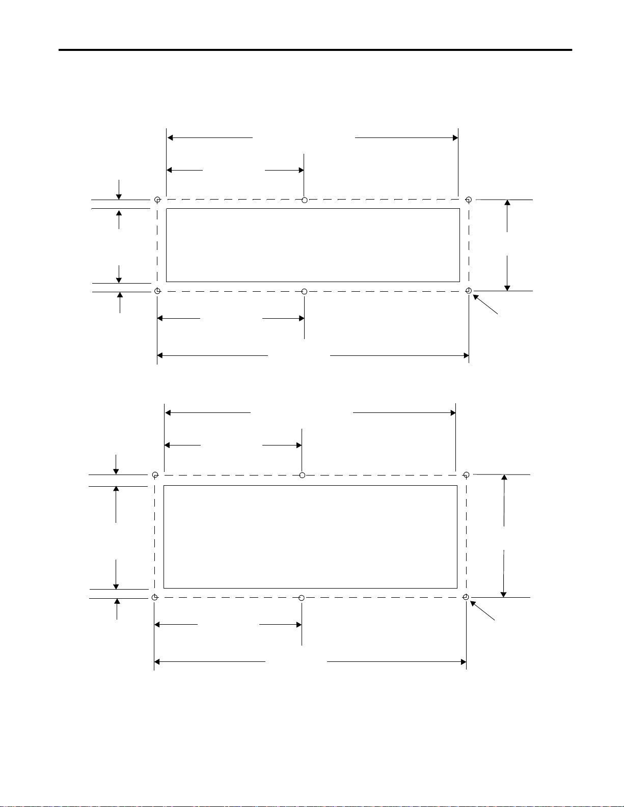
Panel Cutout Dimensions
Dataliner DL40 Plus Message Display (Catalog No. 2706-LV2xX, -LV4xX) 3
All dimensions are in inches (millimeters)
Cutout 13.62 (345.9)
0.19 (4.8)
Cutout
3.50
(88.9)
0.19 (4.8)
0.19 (4.8)
6.81 (173.0)
2-Line DL40 Plus Display
6.94 (176.1)
6.81 (173.0)
(Standard or Slave)
13.87 (352.3)
Cutout 13.62 (345.9)
3.88
(98.4)
0.25 (6.4)
Diameter Hole
6 places
Cutout
5.30
(134.6)
0.19 (4.8)
4-Line DL40 Plus Display
6.94 (176.1)
(Standard or Slave)
13.87 (352.3)
5.68
(144.3)
0.25 (6.4)
Diameter Hole
6 places
Page 4
4 Dataliner DL40 Plus Message Display (Catalog No. 2706-LV2xX, -LV4xX)
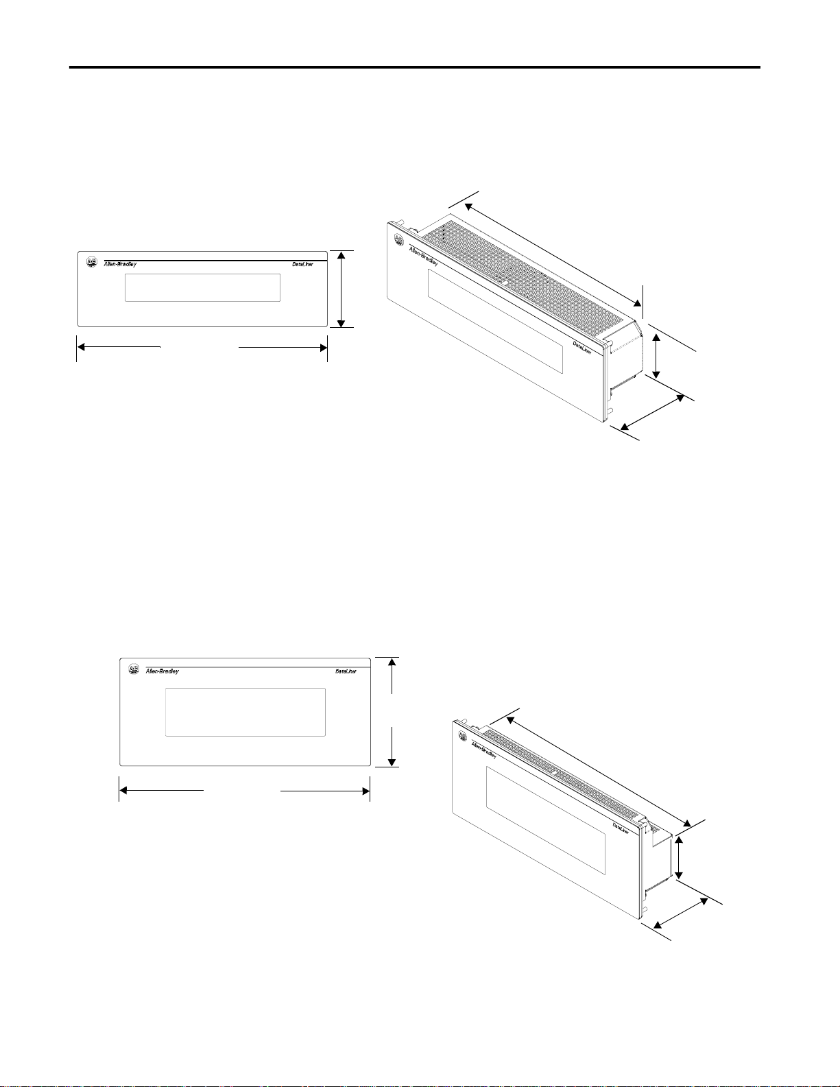
Dimensions
2-Line Display
4.38
(111.3)
13.16
(334.2)
14.357 (365.0)
Dimensions are in inches (millimeters)
Dimensions
4-Line Display
3.16
(80.3)
3.19
(81.0)
6.16
(156.4)
14.357 (365.0)
13.16
(334.2)
3.16
(80.3)
Dimensions are in inches (millimeters)
3.19
(81.0)
Page 5

Dataliner DL40 Plus Message Display (Catalog No. 2706-LV2xX, -LV4xX) 5
Power Connections Before making power connections, make sure that the power is turned off.
The DL40 Plus display requires 100-240Volts AC, 50/60 Hz, 0.60-0.25
Amperes.
ATTENTIO N: Improper wiring of the power
connections may result in damage to the DL40.
!
L2NL1
DIP Switch Settings (Remote I/O Versions)
Black
(Brown)
White
(Blue)
Green
(Green/Yellow)
Three DIP switch banks are located on the back of the display. Access the
DIP switches through a cutout, as shown below.
Set DIP switches using a
thin nonconductive object. Do not use a penci l (broken gra phite pie ces may
short out the internal circuitry).
For details on DIP switch settings, refer to the DL40 Plus User Manual
(Publication 2706-6.1).
Remote I/O Port
SW1
SW2
SW3
RIO
2 S 1
Location of DIP Switches
RS-485
KEYBOARD
RS-232
C
D
V
2
1
D
RELAY
N
250 VAC 3A
G
L1 L2N
Switch Bank #1 (SW-1) sets the rack address.
Switch Bank #2 (SW-2) controls Baud Rate, Fast Reset Sequence,
Block Transfer, Last Chassis, Keyboard Type, Handshaking, Last State,
Select Enable, No PLC Comm Error Message.
Switch Bank #3 (SW- 3) set s the se ri al addr ess. The seria l addre ss refer s
to the address used for triggers received from the serial RS-485 port or
computer keyboard.
Important: Disconnect power from the DL40 Plus before setting any
switch except Select Enable, SW2-9. Select Enable can be changed with
the power on. Switch settings are scanned only on power-up. A new
setting for Select Enable takes effect immediately. All other switches take
effect on power-up or reset.
Page 6

6 Dataliner DL40 Plus Message Display (Catalog No. 2706-LV2xX, -LV4xX)
DIP Switch Settings (Parallel Port Versions)
Two DIP switch banks are located on the back of the module. You can
access the DIP switches through a cutout, as shown below.
Set DIP
switches using a thin nonconductive object. Do not use a pencil (broken
graphite p ieces may short out the inte rnal circuitry).
For details on DIP switch settings, refer to the DL40 Plus User Manual
(Publication No. 2706-6.1).
RS-485
KEYBOARD
RS-232
C
D
V
2
1
D
N
250 VAC 3A
G
RELAY
L1 L2N
SW1
SW2
DIP Switches
Switch Bank #1 (SW-1) c ontrols: Debug M ode, Fast Reset Sequence,
Keyboard Type, Select Enable.
Switch Bank #2 (SW- 2) set s the se ri al addr ess. The seria l addre ss refer s
to the address used for triggers received from the serial RS-485 port or
computer keyboard.
Important: Remove power from the DL40 Plus before setting any switch
except Select En able, SW1-9. Select En able can b e changed wi th the p ower
ON. Switch settings are scanned only on power-up. The new setting for
Select Enable takes effect immediately. The new settings for all other
switches take effect when you power-up or reset the DL40 Plus.
Page 7

Dataliner DL40 Plus Message Display (Catalog No. 2706-LV2xX, -LV4xX) 7
DIP Switch Settings (Slave Versions)
Access the 10-position DIP switches from the back of the display. Set DIP
switches using a thin nonconductive object. Do not use a pencil (broken
graphite p ieces may short out the inte rnal circuitry).
Changes to DIP switches take effect on powerup. The DL40 Plus slave
displays the current settings during its powerup sequence. If you make
changes with the power applied, you will have to cycle power before the
changes take effect. For details on setting DIP switches, refer to the DL40
Plus Slave User Manual (Publication 2706-6.3).
10-Position DIP Sw itch
12345678910
O
N
1234 5678910
O
N
↑
Up = ON
↓
Down = OFF
Additional Information
Positions #1 and #2 of DIP Switch #1 set the operating mode. Default
factory setting is DL Sl ave mode.
Positions #3 and #4 of DIP Switch #1 set the display langua ge. Default
factory setting is English.
Positions #5 and #6 of DIP Switch #1 set th e baud rate. Selec t the baud
rate to match the host device. Default factory setting is 9600.
Positions #7 and #8 of DIP Switch #1 determine the parity. Set the
parity to match the host device. Default factory setting is Even Parity
enabled. Positions #9 and #10 apply to Terminal mode operation.
Positions #1 through #7 of DIP Switch #2 select the serial addr ess of
the DL40 Slave. The address is the binary sum of the value of all the
switches in the Up condition. Default factory setting is address 127.
Positions #8 to #10 are not used.
For additional information on communication port wiring and display
configuration, refer to the DL40 Plus User Manual (Publication 2706-6.1)
or DL40 Plus Slave User Manual (Publication 2706-6.3).
Page 8
8 Dataliner DL40 Plus Message Display (Catalog No. 2706-LV2xX, -LV4xX)
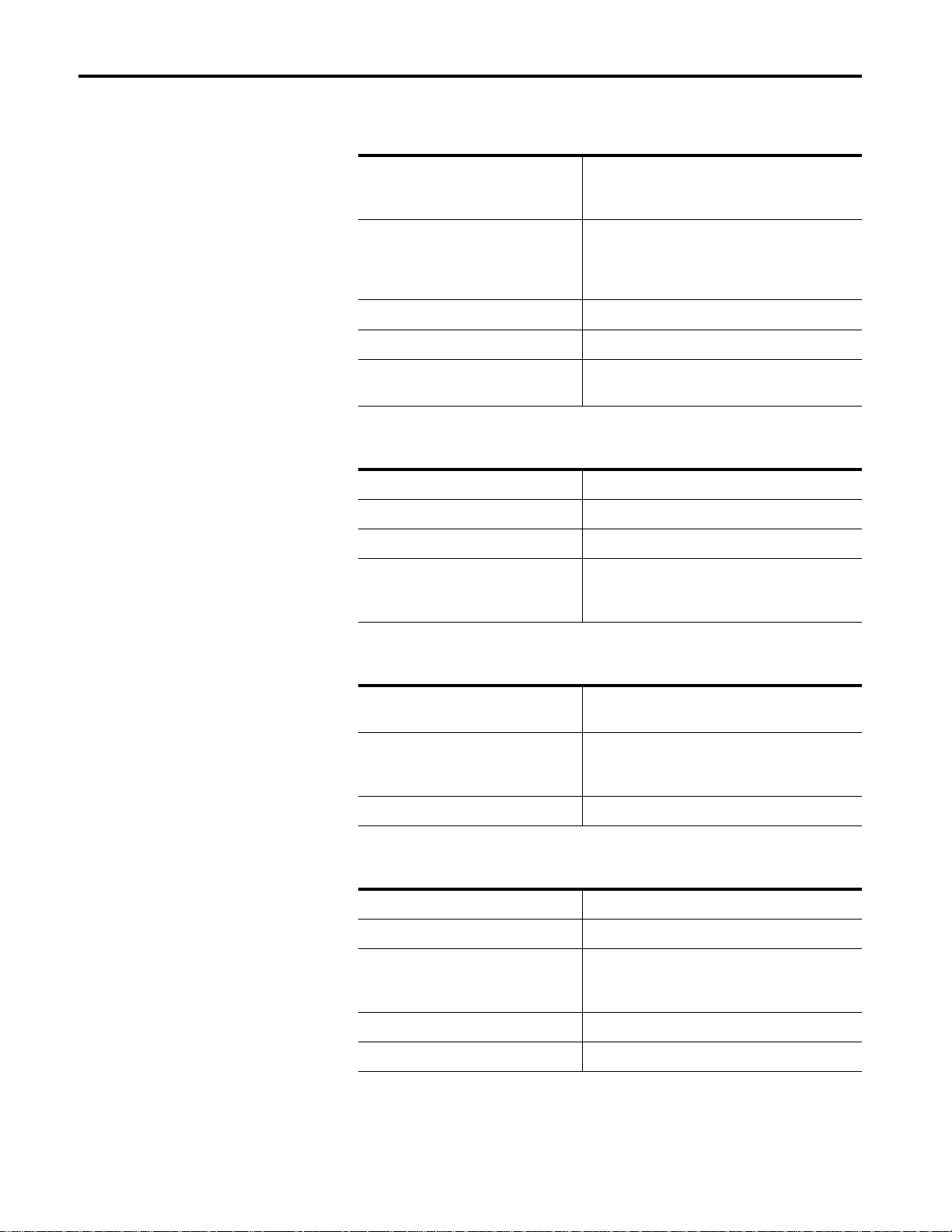
Specifications
Display Characters
Character Height
Two line display
Four line display
Character Set
English
Cyrillic
International
Characters per Display Line 20
Viewing Distance - Approximate 7.6 meters (25 feet)
Character Type Vacuum fluorescent, 5 x 7 dot matrix characters.
11.3 mm (0.44 inch)
11.3 mm (0.44 inch)
Standard & Extended ASCII Characters
Standard & Cyrillic (Russian) Characters
Standard & International ISO 8859-1 Characters
Filtered to blue/green color.
Electrical
Input Voltage 100 - 240V AC, 50-60 Hz, 0.60 - 0.25A
Input Power 60VA
Fuse Type Internal sealed (not user replaceable)
Annunciation Relay
AC Resistive Load
DC Resistive Load
Single N.O. contact
3 Amperes at 240V AC
3 Amperes at 30V DC
Serial Communications
Electrical Interface RS-232 (EIA-/TIA-232-E)
RS-485 (EIA-485)
Baud Rate 300, 1200, 9600, 19200
2400, 4800 (2706-LV2S, -LV2R, -LV4S, -LV4R
only)
Data Format 7 or 8 data bits; odd, even, or no parity
PLC Remote I/O Communications Port (RIO versions only)
Electrical Interface Allen-Bradley Remote I/O Link
Remote I/O Baud Rate 57.6K, 115.2K, or 230.4K
Maximum I/O Cable Distance 10,000 feet (2800m) for 57.6K baud
5,000 feet (1400m) for 115.2k baud
2,500 feet (700m) for 230.4K baud
Rack Sizes 1/4 1/2, 3/4, or 1 (any starting module)
Data Transfer Type Discrete I/O or Block Transfers
Page 9

Dataliner DL40 Plus Message Display (Catalog No. 2706-LV2xX, -LV4xX) 9
Parallel Communications Port (Parallel Port versions only)
Electrical Interface
Parallel Input Port
Logic Low
Indeterminate
Logic High
Data Lines 16 Data Lines,- plus 4 strobe lines
Input Current 5mA per data line at 12 Volts DC
Output Supply +12 Volts DC output voltage source provided,
0 to 24 VDC
High True Logic Low True Logic
0 - 0.8 VDC 3.5 - 24 VDC
0.8 - 3.5 VDC 0.8 - 3.5 VDC
3.5 - 24 VDC 0 - 0.8 VDC
200mA maximum
Keyboard Port (RIO & Parallel Port Versions Only
Electrical Interface Standard Personal Computer Keyboard
IBM PC-XT, -AT compatible
Connector 8-pin DIN (large style connector)
)
Environmental
Temperature Range - Operating 0° to 60°C (+32° to 140°F)
Temperature Range - Storage -40° to 85°C (-40° to 185°F)
Humidity 5% to 95% (non-condensing)
Shock Operating 15G, Non-operating 30G pulses
Vibration Operating 1.0G, Non-operating 2.5G sinusoidal
Mechanical
Enclosure Type UL listed for NEMA Type 12, 13, 4, 4X (indoor use
only) when mounted in a suitable enclosure of
Type 12, 13, 4, 4X, IP65, or IP54
Weight - Approximate
Catalog No. 2706-LV2S, -LV2P, -LV2R
Catalog No. 2706-LV4S, -LV4P, -LV4R
3.6 lbs. (1.6 kg)
4.8 lbs. (2.2 kg)
Page 10
10 Dataliner DL40 Plus Message Display (Catalog No. 2706-LV2xX, -LV4xX)
Certifications
UL Listings UL listed for UL-508 Industrial Control Equipment
European Union Directive Electromagnetic Compatibility Directive
Class I, Groups A, B, C, and D Division 2,
Hazardous Locations
UL Listed for Canadian Safety Standards
CSA 22.2 No. 213
(89/336/EEC)
EN 50082-2
Generic Emission Standard Industrial Environment
EN 50081-2
Generic Immunity Standard Industrial Environment
IEC 1131-2 Programmable Controllers Equipment Class I
Page 11

Dataliner DL40 Plus Message Display (Catalog No. 2706-LV2xX, -LV4xX) 11
Page 12

Copyright 1999 Rockwell International Corporation. Printed in the U.S.A.
41061-115-01(A)
 Loading...