

Page 1
Installation Instructions
!
!
1769-SM2 Compact I/O DSI/Modbus
Network Communication Module
This document instructs how to install a 1769-SM2 Compact I/O DSI/Modbus
Network Communication Module into the controller.
ATTENTION: Risk of equipment damage exists. Remove power before
installing or removing the 1769-SM2 module. When you install or remove
the module with power applied, an electrical arc may occur. An electrical
arc can cause personal injury or equipment damage by:
• Sending an erroneous signal to your system’s field devices, causing
unintended machine motion.
• Causing an explosion in a hazardous environment.
Electrical arcing causes excessive wear to contacts on both the module
and its mating connector. Worn contacts may create electrical resistance.
ATTENTION: Risk of equipment damage exists. The 1769-SM2
module contains ESD (Electrostatic Discharge) sensitive parts that can be
damaged if you do not follow ESD control procedures. Static control
precautions are required when handling the module. If you are unfamiliar
with static control procedures, refer to Guarding Against Electrostatic
Damage, publication 8000-4.5.2.
Related Documentation
Document Description
1769-SM2 Compact I/O DSI/Modbus
Network Communication Module User
Manual, publication 1769-UM013
Guarding Against Electrostatic Damage,
publication 8000-4.5.2
Wiring and Grounding Guidelines for PWM
AC Drives, publication DRIVES-IN001
Documentation can be obtained online at www.rockwellautomation.com/literature.
To order paper copies of technical documentation, contact your local Rockwell
Automation distributor or sales representative.
For information such as firmware updates and answers to drive-related questions, go
to the Drives Service & Support web site at www.ab.com/support/abdrives
on the “Downloads” or “Knowledgebase” link.
Step 1
Remove power from the controller.
Provides complete installation, wiring, setup, and
communication information for the 1769-SM2 Network
Communication Module.
Provides static control procedures for protecting
electrostatic discharge sensitive parts.
Guidelines for proper wiring, grounding, and shielding, and
standard practices for noise protection.
and click
Page 2
2
!
ATTENTION: Risk of equipment damage exists. When
attaching the 1769-SM2 module to a Compact I/O system, it is
very important that the bus connectors are securely locked
together to ensure proper electrical connection. Failure to do
this may cause an electrical arc, which can cause personal
injury or equipment damage.
Step 2
Step 3
Set the 1769-SM2 module Configuration Mode switch and Operating
Mode (Single/Multi-Drive) switch to appropriate positions. For complete
switch setting details, see the 1769-SM2 module User Manual.
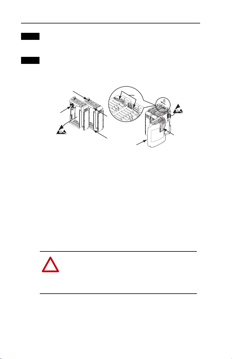
Assemble the 1769-SM2 module to the controller. It can be attached to
adjacent controller modules before or after mounting. For mounting
instructions, see Step 4A (Panel Mounting) or Step 4B (DIN Rail
Mounting). To work with a system that is already mounted, see Step 5.
1
3
A. Disconnect power.
2
2
4
5
7
6
B. Install the 1769-SM2 module within 4 slots of the power supply.
C. Check that the bus lever (item 1) of the 1769-SM2 module is in the
unlocked (fully right) position.
D. Use the upper and lower tongue-and-groove slots (item 2) to secure the
modules together.
E. Move the 1769-SM2 module back along the tongue-and-groove slots
until the bus connectors (item 3) line up with each other.
F. Use your fingers or a small screwdriver to push the bus lever back
slightly to clear the positioning tab (item 4).
G. Move the 1769-SM2 module’s bus lever fully to the left (item 5) until it
clicks. Ensure it is locked firmly in place.
H. Attach an end cap terminator (item 6) to the last module in the system
by using the tongue-and-groove slots as before.
I. Lock the end cap bus terminator (item 7).
Important: A 1769-ECR or 1769-ECL right or left end cap must be used
to terminate the end cap of the serial communication bus.
Page 3

!
ATTENTION: Risk of equipment damage exists. During
panel or DIN rail mounting of all devices, be sure that all debris
(metal chips, wire strands, etc.) is kept from falling into the
1769-SM2 module. Debris that falls into the module could
cause damage on power up.
Compact I/O
Compact I/O
Compact I/O
Compact I/O
Compact I/O
End Cap or Cable
Controller
To p
Bottom
Side
Side
132 mm (5.19 in)
122.6 mm (4.83 in)
118 mm (4.65 in)
147.4 mm (5.81 in)
14.7 mm
(0.58 in)
35 mm
(1.38 in)
168 mm
(6.62 in)
147 mm
(5.79 in)
35 mm
(1.38 in)
13.5 mm
(0.53 in)
59 mm
(2.32 in)
59 mm
(2.32 in)
Mounting Hole
Dimension
DIN Rail
Center Line
28.5 mm
(1.12 in)
DSI
MODULE
CH1
CH2
CH3
C
H
1
C
H
2
C
H
3
Step 4
3
Mount the 1769-SM2 module.
Maintain spacing from enclosure walls, wireways, adjacent equipment, etc.
Allow 50 mm (2 in.) of space on all sides for adequate ventilation as shown.
Allow at least 140 mm (5.5 in.) of enclosure depth to accomodate the
1769-SM2 module.
A. Panel Mounting — Mount the 1769-SM2 module to a panel using two
screws per module. Use M4 or #8 panhead screws. Mounting screws are
required on every module.
Using a Dimensional Drawing
NOTE: All dimensions are in mm (inches). Hole spacing tolerance:
± 0.04 mm (0.016 in.).
Figure 1 1769-SM2 Module with MicroLogix 1500 Base Unit and Processor
Page 4

4
Figure 2 1769-SM2 Module with CompactLogix Controller
50 mm
Mounting Hole
Dimension
132 mm (5.19 in)
122.6 mm (4.83 in)
59 mm
(2.32 in)
118 mm (4.65 in)
59 mm
(2.32 in)
(1.97 in)
40 mm
(1.58 in)
35 mm
(1.38 in)
35 mm
(1.38 in)
(2.76 in)
35 mm
(1.38 in)
70 mm
35 mm
(1.38 in)
35 mm
(1.38 in)
35 mm
(1.38 in)
MODULE
CH1
CH2
DSI
C
H
1
C
H
2
C
H
3
28.5 mm
(1.12 in)
CH3
147.4 mm (5.81 in)
DIN Rail
Center Line
14.7 mm
(0.58 in)
Figure 3 1769-SM2 Module with Remote 1769-Based Adapter
Mounting Hole
Dimension
132 mm (5.19 in)
122.6 mm (4.83 in)
59 mm
(2.32 in)
118 mm (4.65 in)
59 mm
(2.32 in)
50 mm
(1.97 in)
40 mm
(1.58 in)
MS
IO
NS
DIAG
35 mm
(1.38 in)
35 mm
(1.38 in)
DIN Rail
Center Line
35 mm
(1.38 in)
70 mm
(2.76 in)
35 mm
(1.38 in)
14.7 mm
(0.58 in)
35 mm
(1.38 in)
35 mm
(1.38 in)
MODULE
CH1
CH2
DSI
C
H
1
C
H
2
C
H
3
28.5 mm
(1.12 in)
CH3
147.4 mm (5.81 in)
Using Module as a Template
The following procedure enables you to use the assembled modules as a
template for drilling holes in the panel. Due to module mounting hole
tolerance, it is important to follow these steps:
a. On a clean work surface, assemble no more than three modules.
b. Using the assembled modules as a template, carefully mark the
center of all module-mounting holes on the panel.
c. Return the assembled modules to the clean work surface, including
any previously mounted modules.
d. Drill and tap the mounting holes for the recommended M4 or #8
screw.
Page 5

!
ATTENTION: Risk of equipment damage exists. Remove
power before installing or removing the 1769-SM2 module.
When you install or remove the module with power applied, an
electrical arc may occur. An electrical arc can cause personal
injury or equipment damage by:
• Sending an erroneous signal to your system’s filed devices,
causing unintended machine motion.
• Causing an explosion in a hazardous environment.
Electrical arcing causes excessive wear to contacts on both the
module and its mating connector. Worn contacts may create
electrical resistance.
TIP: It may be necessary to slightly move the module from
front to back to remove it, or in a panel-mounted system, to
loosen the screws of adjacent modules.
Step 5
5
e. Place the modules back on the panel, and check for proper hole
alignment.
f. Attach the modules to the panel using the mounting screws.
B. DIN Rail Mounting — The 1769-SM2 module can be mounted using
the following DIN rails:
• 35 x 7.5 mm (EN 50 022 - 35 x 7.5)
• 35 x 15 mm (EN 50 022 - 35 x 15)
Before mounting the module on a DIN rail, close the DIN rail latches.
Press the DIN rail mounting area of the module against the DIN rail.
The latches will momentarily open and lock into place.
Replacing the module within a system. The 1769-SM2 module can be
replaced while the system is mounted to a panel (or DIN rail).
A. Remove power.
B. Unplug the communications cable from each port (CH1, CH2, CH3) on
the 1769-SM2 module. Note each drive and the port to which it is
connected.
C. Remove the upper and lower mounting screws from the module (or
open the DIN latches using a flat-blade screwdriver).
D. On the right-side adjacent module, move its bus lever to the right
(unlock) to disconnect it from the module being removed.
E. Gently slide the disconnected 1769-SM2 module forward. If you feel
excessive resistance, make sure that you disconnected the module from
the bus and that you removed both mounting screws (or opened the DIN
latches).
Page 6

6
Step 6
Step 7
F. Before installing the replacement 1769-SM2 module, be sure that the
bus lever on the right-side adjacent module is in the unlocked (fully
right) position.
G. Slide the replacement 1769-SM2 module into the open slot.
H. Connect the 1769-SM2 module and adjacent modules together by
locking (fully left) the bus levers on the 1769-SM2 module and the
right-side adjacent module.
I. Replace the mounting screws (or snap the module onto the DIN rail).
J. Plug the appropriate communications cable into its respective port on
the 1769-SM2 module.
K. Restore 1769-SM2 module configuration using an appropriate
configuration tool.
Connect the module to the drive(s).
For information and network wiring examples, see the 1769-SM2 User
Manual.
NOTE: For Single or Multi-Drive mode, there is a maximum cable
distance limit per channel. See the 1769-SM2 User Manual for details.
Ground the module.
The 1769-SM2 module is intended to be mounted to a well-grounded
mounting surface such as a metal panel. Additional grounding connections
from the module’s mounting tabs or DIN rail (if used) are not required
unless the mounting surface cannot be grounded. For additional
information, refer to Industrial Automation Wiring and Grounding
Guidelines, publication No. 1770-4.1.
For details on shielded connector and unshielded connector grounding
requirements, see the 1769-SM2 Compact I/O DSI/Modbus Network
Communication User Manual, publication 1769-UM013.
Page 7

!
ATTENTION: Risk of equipment damage, injury, or death
exists. Unpredictable operation may occur if you fail to verify
that parameter settings are compatible with your application.
Verify that settings are compatible with your application before
applying power to the drive.
Step 8
Step 9
Apply power.
A. Apply power to the controller. The status indicators can be viewed on
the front of the 1769-SM2 module after power has been applied.
B. Apply power to the drive(s). When you apply power to the 1769-SM2
module, controller, and network for the first time, the status indicators
should be green after an initialization. If the status indicators go red,
there is a problem. Refer to the “Troubleshooting” chapter in the
1769-SM2 Compact I/O DSI/Modbus Network Communication User
Manual.
Read the 1769-SM2 Compact I/O DSI/Modbus Network Communication
User Manual for information to configure and determine how to apply the
network to the host product(s).
7
Page 8

Notes:
U.S. Allen-Bradley Drives Technical Support
Tel: (1) 262.512.8176, Fax: (1) 262.512.2222, Email: support@drives.ra.rockwell.com, Online: www.ab.com/support/abdrives
www.rockwellautomation.com
Power, Control and Information Solutions Headquarters
Americas: Rockwell Automation, 1201 South Second Street,
/
Middle East/Africa: Rockwell Automati
Europe
Asia Pacific: Rockwell Automation, Level 14, Core F, Cyberport 3, 100 Cyberport Road, Hong Kong, Tel: (852) 2887 4788, Fax: (852) 2508 1846
Publication 1769-IN084A-EN-P – May, 2012 P/N-148232
Milwaukee, WI 53204-2496 USA,
on,
Pegasus Park, De Kleetlaan 12a,
Copyright © 2012 Rockwell Automation, Inc. All rights reserved. Printed in USA.
Tel :
1831 Diegem, Belgium,
(1) 414.382.2000, Fax: (1) 414.382.4444
Tel: (32) 2 663 0600, Fax: (32) 2 663 0640
 Loading...