

Page 1

PowerFlex 1769-SM2
Compact I/O DSI/Modbus
Communications Module
Firmware Version 1.xxx
User Manual
Page 2
Important User Information
Solid state equipment has operational characteristics differing from those of
electromechanical equipment. Safety Guidelines for the Application, Installation
and Maintenance of Solid State Controls (Publication SGI-1.1 available from your
local Rockwell Automation sales office or online at http://
www.rockwellautomation.com/literature) describes some important differences
between solid state equipment and hard-wired electromechanical devices. Because
of this difference, and also because of the wide variety of uses for solid state
equipment, all persons responsible for applying this equipment must satisfy
themselves that each intended application of this equipment is acceptable.
In no event will Rockwell Automation, Inc. be responsible or liable for indirect or
consequential damages resulting from the use or application of this equipment.
The examples and diagrams in this manual are included solely for illustrative
purposes. Because of the many variables and requirements associated with any
particular installation, Rockwell Automation, Inc. cannot assume responsibility or
liability for actual use based on the examples and diagrams.
No patent liability is assumed by Rockwell Automation, Inc. with respect to use of
information, circuits, equipment, or software described in this manual.
Reproduction of the contents of this manual, in whole or in part, without written
permission of Rockwell Automation, Inc. is prohibited.
Throughout this manual, when necessary we use notes to make you aware of safety
considerations.
WARNING: Identifies information about practices or circumstances
that can cause an explosion in a hazardous environment, which may
!
!
lead to personal injury or death, property damage, or economic loss.
Important: Identifies information that is critical for successful application and
!
!
Allen-Bradley, PowerFlex, DriveExplorer, DriveExecutive, DriveTools SP, CompactLogix, MicroLogix, DSI, RSNetWorx for
DeviceNet, and ControlFLASH are trademarks of Rockwell Automation, Inc.
Trademarks not belonging to Rockwell Automation are property of their respective companies.
understanding of the product.
ATTENTION: Identifies information about practices or circumstances
that can lead to personal injury or death, property damage, or economic
loss. Attentions help you identify a hazard, avoid a hazard, and
recognize the consequences.
Shock Hazard labels may be located on or inside the equipment (e.g.,
drive or motor) to alert people that dangerous voltage may be present.
Burn Hazard labels may be located on or inside the equipment (e.g.,
drive or motor) to alert people that surfaces may be at dangerous
temperatures.
Page 3

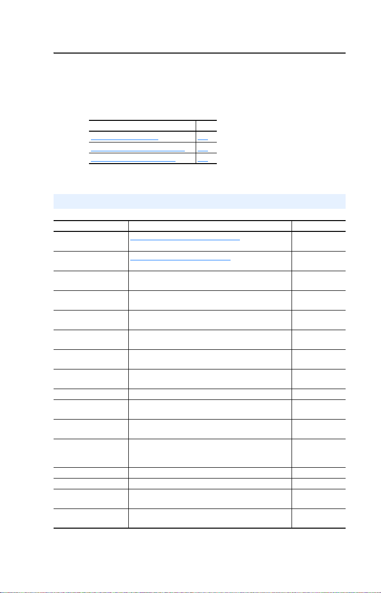
Summary of Changes
The information below summarizes the changes made to this manual
since version 1769-UM013B-EN-P (January 2006):
Description Page(s)
Changed Figures 1.3 and 1.4 to correctly show the wiring of the RJ45
daisy-chained connectors.
In the “Compatible Products” section, added the PowerFlex 4M and
PowerFlex 40P drives.
Moved the Module Start-Up Status Indication table from Chapter 1 to
Chapter 2 after the “Applying Power” section.
Added the subsection “Special Case—Data Entry for 2 Stop Bits
Communication.”
Changed module Parameters 15 - [RTU Parity 1], 30 - [RTU Parity 2], and
45 - [RTU Parity 3] per 1769-SM2 firmware v2.001 update. The parameter
numbers remain the same but the parameter names changed from [RTU
Parity x] to [RTU Format x]. Also, in addition to parity (None, Even or Odd),
the parameter function changed to include choice of stop bits (1 or 2).
In the “Using Reference/Feedback” section, revised table to include
PowerFlex 4M and PowerFlex 40P drives.
Added the new section “Using RSLinx Classic” to Chapter 8. 8-2
Updated the Logic Command word and Logic Status word information to
include data for all PowerFlex 4-Class drives.
and 1-5
1-4
1-6
2-15
3-8
3-17
, B-3,
B-5, and B-7
4-4
D-1 and D-2
Page 4

soc-ii
Page 5

Preface About This Manual
Related Documentation . . . . . . . . . . . . . . . . . . . . . . . . . . . . . P-1
Rockwell Automation Support. . . . . . . . . . . . . . . . . . . . . . . . P-2
Conventions Used in this Manual . . . . . . . . . . . . . . . . . . . . . P-3
Chapter 1 Getting Started
Components . . . . . . . . . . . . . . . . . . . . . . . . . . . . . . . . . . . . . . 1-1
Features . . . . . . . . . . . . . . . . . . . . . . . . . . . . . . . . . . . . . . . . . 1-2
Single Mode vs. Multi-Drive Mode. . . . . . . . . . . . . . . . . . . . 1-3
Compatible Products . . . . . . . . . . . . . . . . . . . . . . . . . . . . . . . 1-6
Required Equipment . . . . . . . . . . . . . . . . . . . . . . . . . . . . . . . 1-6
Safety Precautions . . . . . . . . . . . . . . . . . . . . . . . . . . . . . . . . . 1-7
Quick Start . . . . . . . . . . . . . . . . . . . . . . . . . . . . . . . . . . . . . . . 1-9
Status Indicators. . . . . . . . . . . . . . . . . . . . . . . . . . . . . . . . . . 1-10
Chapter 2 Installing the Module
Preparing for an Installation. . . . . . . . . . . . . . . . . . . . . . . . . . 2-1
Removing Power . . . . . . . . . . . . . . . . . . . . . . . . . . . . . . . . . . 2-2
Setting the Configuration Mode Switch. . . . . . . . . . . . . . . . . 2-3
Setting the Operating Mode Switch (Single/Multi-Drive). . . 2-4
Assembling the Module to the Controller . . . . . . . . . . . . . . . 2-5
Mounting the Module. . . . . . . . . . . . . . . . . . . . . . . . . . . . . . . 2-6
Replacing the Module within a System . . . . . . . . . . . . . . . . . 2-9
Connecting Drive(s) to the Module . . . . . . . . . . . . . . . . . . . 2-10
Grounding the Module. . . . . . . . . . . . . . . . . . . . . . . . . . . . . 2-12
Network Cable Strain Relief . . . . . . . . . . . . . . . . . . . . . . . . 2-14
Applying Power . . . . . . . . . . . . . . . . . . . . . . . . . . . . . . . . . . 2-14
Viewing Start-Up Status Indicators . . . . . . . . . . . . . . . . . . . 2-15
Table of Contents
Chapter 3 Configuring the Module
Determining I/O Image Size . . . . . . . . . . . . . . . . . . . . . . . . . 3-1
Configuration Tools . . . . . . . . . . . . . . . . . . . . . . . . . . . . . . . . 3-2
Configuration Methods . . . . . . . . . . . . . . . . . . . . . . . . . . . . . 3-3
Controller Mode. . . . . . . . . . . . . . . . . . . . . . . . . . . . . . . . . . . 3-3
Parameter Mode . . . . . . . . . . . . . . . . . . . . . . . . . . . . . . . . . . 3-12
Using the Optional, External PowerFlex 4-Class HIM . . . . 3-13
Setting the I/O Configuration (Multi-Drive Mode Only). . . 3-14
Setting an Idle Action (Single and Multi-Drive Mode) . . . . 3-15
Setting Drive Node Addresses (Multi-Drive Mode Only). . 3-16
Configuring the Modbus RTU Master Parameters. . . . . . . . 3-17
Resetting the Module . . . . . . . . . . . . . . . . . . . . . . . . . . . . . . 3-20
Viewing the Module Status Using Parameters. . . . . . . . . . . 3-21
Flash Updating the Module . . . . . . . . . . . . . . . . . . . . . . . . . 3-22
Page 6

ii Table of Contents
Chapter 4 Understanding the I/O Image
Module Control Word . . . . . . . . . . . . . . . . . . . . . . . . . . . . . . 4-2
Module Status Word. . . . . . . . . . . . . . . . . . . . . . . . . . . . . . . . 4-3
Using Logic Command/Status . . . . . . . . . . . . . . . . . . . . . . . . 4-4
Using Reference/Feedback . . . . . . . . . . . . . . . . . . . . . . . . . . 4-4
Chapter 5 Understanding Explicit Messaging
Formatting Explicit Messages . . . . . . . . . . . . . . . . . . . . . . . . 5-2
Modbus RTU Master Operation Messages . . . . . . . . . . . . . . 5-9
Chapter 6 MicroLogix 1500 Example Ladder Programs
Single Mode . . . . . . . . . . . . . . . . . . . . . . . . . . . . . . . . . . . . . . 6-1
Multi-Drive Mode . . . . . . . . . . . . . . . . . . . . . . . . . . . . . . . . . 6-8
Chapter 7 CompactLogix Example Ladder Programs
Single Mode . . . . . . . . . . . . . . . . . . . . . . . . . . . . . . . . . . . . . . 7-1
Multi-Drive Mode . . . . . . . . . . . . . . . . . . . . . . . . . . . . . . . . 7-10
Chapter 8 ControlLogix w/1769-ADN DeviceNet Example Ladder
Program
Single Mode . . . . . . . . . . . . . . . . . . . . . . . . . . . . . . . . . . . . . 8-1
Using RSLinx Classic . . . . . . . . . . . . . . . . . . . . . . . . . . . . . . 8-2
Using RSNetWorx for DeviceNet . . . . . . . . . . . . . . . . . . . . . 8-3
Setting Up the 1769-ADN . . . . . . . . . . . . . . . . . . . . . . . . . . . 8-4
Registering the 1769-SM2 EDS File . . . . . . . . . . . . . . . . . . . 8-8
PowerFlex 40 Settings . . . . . . . . . . . . . . . . . . . . . . . . . . . . . 8-12
1769-SM2 Settings. . . . . . . . . . . . . . . . . . . . . . . . . . . . . . . . 8-12
ControlLogix w/1769-ADN Example Program. . . . . . . . . . 8-13
Example Program Data Table . . . . . . . . . . . . . . . . . . . . . . . 8-21
Chapter 9 Troubleshooting
Locating the Status Indicators . . . . . . . . . . . . . . . . . . . . . . . . 9-1
MODULE Status Indicator . . . . . . . . . . . . . . . . . . . . . . . . . . 9-2
CH1…CH3 Status Indicators. . . . . . . . . . . . . . . . . . . . . . . . . 9-3
Viewing Module Diagnostic Items. . . . . . . . . . . . . . . . . . . . . 9-4
Viewing and Clearing Events. . . . . . . . . . . . . . . . . . . . . . . . . 9-6
Appendix A Specifications
Communications . . . . . . . . . . . . . . . . . . . . . . . . . . . . . . . . . A-1
Electrical . . . . . . . . . . . . . . . . . . . . . . . . . . . . . . . . . . . . . . . A-1
Mechanical . . . . . . . . . . . . . . . . . . . . . . . . . . . . . . . . . . . . . . A-1
Environmental . . . . . . . . . . . . . . . . . . . . . . . . . . . . . . . . . . . A-2
Regulatory Compliance . . . . . . . . . . . . . . . . . . . . . . . . . . . . A-2
DSI Cable Requirements . . . . . . . . . . . . . . . . . . . . . . . . . . . A-2
Page 7

Table of Contents iii
Appendix B Module Parameters
About Parameter Numbers. . . . . . . . . . . . . . . . . . . . . . . . . . . B-1
Parameter List . . . . . . . . . . . . . . . . . . . . . . . . . . . . . . . . . . . . B-1
Appendix C CIP/DSI Objects
CIP Identity Object . . . . . . . . . . . . . . . . . . . . . . . . . . . . . . . . C-3
CIP Parameter Object. . . . . . . . . . . . . . . . . . . . . . . . . . . . . . . C-4
DSI Device Object. . . . . . . . . . . . . . . . . . . . . . . . . . . . . . . . . C-7
DSI Parameter Object . . . . . . . . . . . . . . . . . . . . . . . . . . . . . C-10
DSI Fault Object . . . . . . . . . . . . . . . . . . . . . . . . . . . . . . . . . C-14
DSI Diagnostic Object . . . . . . . . . . . . . . . . . . . . . . . . . . . . . C-16
Appendix D PowerFlex 4-Class Drives Logic Command/Status
Words
Logic Command Word. . . . . . . . . . . . . . . . . . . . . . . . . . . . . D-1
Logic Status Word . . . . . . . . . . . . . . . . . . . . . . . . . . . . . . . . D-2
Glossary
Index
Page 8

iv Table of Contents
Page 9
Preface
About This Manual
Topic Page
Related Documentation
Conventions Used in this Manual P-3
Rockwell Automation Support P-2
Related Documentation
For: Refer to: Publication
DriveExplorer™ http://www.ab.com/drives/driveexplorer
DriveTools™ SP
(includes DriveExecutive)
PowerFlex 4-Class HIM
(22-HIM-A3 / -C2S)
PowerFlex
PowerFlex
PowerFlex
PowerFlex
PowerFlex
RSLinx
RSLogix™ 500
RSLogix™ 5000
RSNetWorx™ for
DeviceNet
MicroLogix™ 1500 MicroLogix 1500 Programmable Controllers User Manual
CompactLogix™ CompactLogix System User Manual 1769-UM007
ControlLogix
Modbus RTU
Specification
PowerFlex 7-Class Drive
Connectivity
(1)
®
4 Drive PowerFlex 4 User Manual
®
4M Drive PowerFlex 4M User Manual
®
40 Drive PowerFlex 40 User Manual
®
40P Drive PowerFlex 40P User Manual
®
400 Drive PowerFlex 400 User Manual
®
Classic Getting Results with RSLinx Guide, and online help
®
The online help is installed with the software.
DriveExplorer online help
http://www.ab.com/drives/drivetools
DriveExecutive online help
HIM Quick Reference 22HIM-QR001
PowerFlex 4 Quick Start
PowerFlex 4M Quick Start
PowerFlex 40 Quick Start
PowerFlex 40P Quick Start
PowerFlex 400 Quick Start
RSLogix 500 Getting Results Guide, and online help
RSLogix 5000 Getting Results Guide, and online help
RSNetWorx for DeviceNet Getting Results Guide, and
online help
MicroLogix 1200 and MicroLogix 1500 Programmable
ControlLogix Gateway System User Manual 1756-6.5.13
Modbus – ida.org —
20-COMM-H RS-485 HVAC Adapter User Manual 20COMM-UM009
(1)
Controllers Reference Manual
P-1
(1)
(1)
, and
, and
—
—
22A-UM001
22A-QS-001
22F-UM001
22F-QS-001
22B-UM001
22B-QS-001
22D-UM001
22D-QS-001
22C-UM001
22C-QS-001
(1)
LINX-GR001
(1)
LG500-GR002
(1)
9399-RLD300GR
DNET-GR001
1764-UM001
1762-RM001
Page 10

P-2 About This Manual
You can view or download publications at http://
literature.rockwellautomation.com. To order paper copies of technical
documentation, contact your local Rockwell Automation distributor or
sales representative.
To find your local Rockwell Automation distributor or sales
representative, visit www.rockwellautomation.com/locations
For information such as firmware updates or answers to drive-related
questions, go to the Drives Service & Support web site at www.ab.com/
support/abdrives and click on the “Downloads” or “Knowledgebase” link.
Rockwell Automation Support
Rockwell Automation, Inc. offers support services worldwide, with over
75 sales/support offices, over 500 authorized distributors, and over 250
authorized systems integrators located through the United States alone.
In addition, Rockwell Automation, Inc. representatives are in every
major country in the world.
Local Support
.
Contact your local Rockwell Automation, Inc. representative for:
• Sales and order support
• Product technical training
• Warranty support
• Support service agreements
Technical Assistance
For technical assistance, please review the information in Chapter 9,
Troubleshooting, first. If you still have problems, then access the
Allen-Bradley Technical Support web site at www.ab.com/support/
abdrives or contact Rockwell Automation, Inc.
Page 11

About This Manual P-3
Conventions Used in this Manual
The following conventions are used throughout this manual:
• Parameter names are shown in the format Parameter xx - [*]. The
xx represents the parameter number. The * represents the parameter
name. For example Parameter 01 - [Config Mode].
• Menu commands are shown in bold type face and follow the format
Menu > Command. For example, if you read “Select File > Open,”
you should click the File menu and then click the Open command.
• RSNetWorx for DeviceNet (version 4.01) and RSLinx (version 2.41)
were used for the screen shots in this manual. Different versions of
the software may differ in appearance and procedures.
• The firmware release is displayed as FRN X.xxx. The “FRN”
signifies Firmware Release Number. The “X” is the major release
number. The “xxx” is the minor update number. This manual is for
Firmware release 1.xxx.
Page 12

P-4 About This Manual
Notes:
Page 13
Chapter 1
Getting Started
The 1769-SM2 Compact I/O to DSI module provides a Compact I/O
connection for PowerFlex 4-Class drives. It can be used with a
MicroLogix 1500, CompactLogix, or a remote 1769-based adapter such
as the 1769-ADN.
Topic Page Topic Page
Components
Features 1-2 Safety Precautions 1-7
Single Mode vs. Multi-Drive Mode 1-3 Quick Start 1-9
Compatible Products 1-6 Status Indicators 1-10
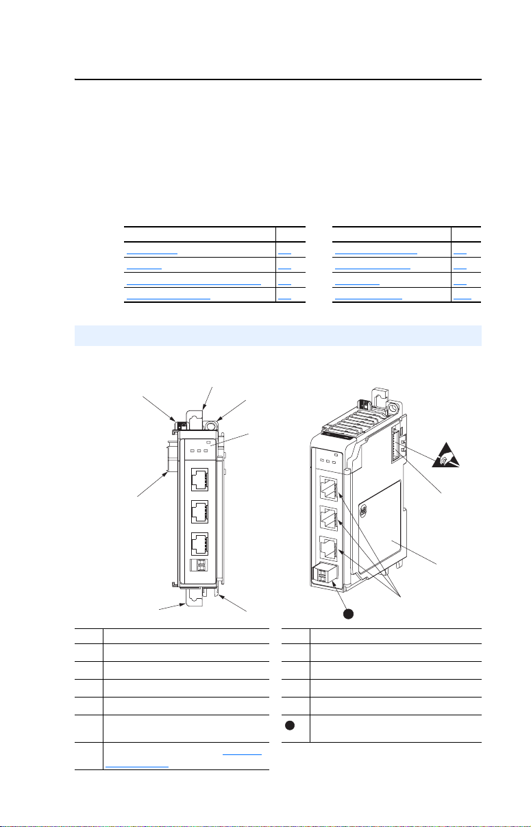
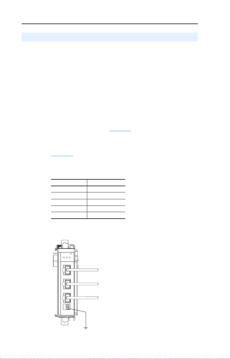
Components
Figure 1.1 Components of the Module
➊
➋
1-1 Required Equipment 1-6
➍
MODULE
CH1
CH2 CH3
DSI
C
H
1
➐
C
H
2
C
H
3
➏
MODULE
C
H
1
C
H
2
C
H
3
I
S
D
C
H
1
C
H
2
C
H
3
➌
Item Part Item Part
Bus lever (with locking function)
➊
Upper DIN rail latch
➋
Lower DIN rail latch
➌
Upper panel mounting tab
➍
Lower panel mounting tab Terminal block for network communication
➎
Module status indicators (see Chapter 9,
➏
Troubleshooting
for details).
➎
➐
➑
➒
➓
11
11
Movable bus connector with female pins
Bus connector with male pins
Nameplate label
DSI connectors
shielding and earth ground wire.
➓
➑
➒
Page 14

1-2 Getting Started
Features
The 1769-SM2 Compact I/O to DSI module features include:
• Three Compact I/O connection channels for PowerFlex 4-Class
drives. Up to 3 drives can be connected in Single mode (1 per
channel) and up to 15 drives can be connected in Multi-Drive mode
(5 per channel). Any channel in Multi-Drive mode can also be
configured to operate as a Modbus RTU Master, allowing
connectivity to a maximum of 31 other Modbus RTU Slave devices,
such as PowerFlex 7-Class drives with 20-COMM-H RS485 HVAC
adapters.
• Use as expansion I/O on MicroLogix 1500 and CompactLogix
controllers or with a remote 1769-based adapter. It receives the
required power from the Compact I/O backplane.
• Parameter-configurable I/O, including Logic Command/Reference
and Logic Status/Feedback for each connected drive.
• Explicit messaging (parameter read/write, etc.) support for:
– MicroLogix 1500 LRP Series C systems when used with
RSLogix 500 v6.30 (or higher)
– Enhanced CompactLogix processors, such as the -L31, -L32E,
and -L35E
Explicit messaging is NOT available for CompactLogix -L20 and
-L30 processors, or 1769-ADN DeviceNet adapters.
• User-defined fault actions to determine how the module and
connected drives respond to controllers in idle mode (Idle Action).
• Bi-color (red/green) status indicators to report the status of the
module and channel communications.
• Compatibility with various configuration tools to configure the
module and connected drive(s). The tools include an optional,
external PowerFlex 4-Class HIM (22-HIM-A3 or 22-HIM-C2S), and
drive-configuration software such as DriveExplorer v3.01 (or higher)
or DriveExecutive v4.01 (or higher).
Page 15
Getting Started 1-3
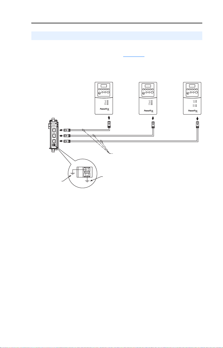
Single Mode vs. Multi-Drive Mode
Single mode is a one-to-one connection, where a channel is connected to
a single PowerFlex 4-Class drive (Figure 1.2
Figure 1.2 Single Mode Wiring Example
1769-SM2
CH1
CH2
CH3
Module
MODULE
CH1
CH2 CH3
C
H
1
C
H
2
C
H
3
AK-U0-RJ45-TB2P
Terminal Block
Connector
22-RJ45CBL-C20 Cable, or User-Supplied Wire
(recommend Belden No. 3105A or equivalent)
with AK-U0-RJ45-TB2P terminal block connectors
AK-U0-RJ45-TB2P
).
Powerflex 4-Class Drives
Terminal Block
Connector
AK-U0-RJ45-TB2P
Terminal Block
Connector
Earth Ground
Connection
Ground Wire Connection
(for network communication
shielding)
An additional DSI peripheral device, such as an external PowerFlex
4-Class HIM or Serial Converter module (22-SCM-232) with a software
tool, can be used with each drive. An AK-U0-RJ45-SC1 DSI Splitter
cable can be used to split the RJ45 connector on the drive into two RJ45
connectors.
Page 16
1-4 Getting Started
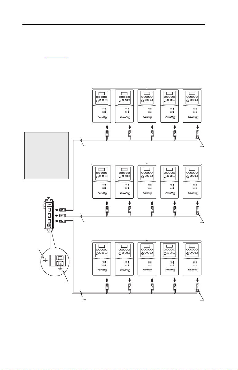
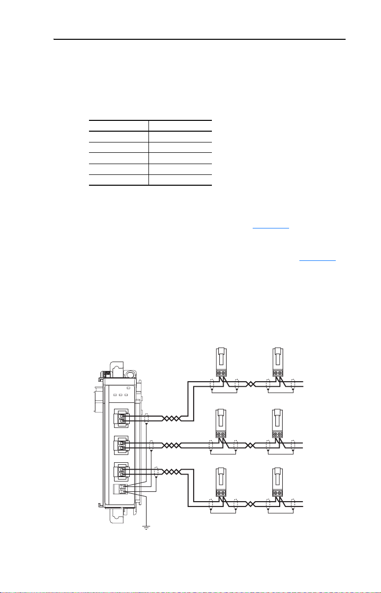
Multi-Drive mode enables increased connectivity, where one to five
PowerFlex 4-Class drives can be connected per channel. All of the drives
are daisy-chained to the 1769-SM2 module over RS-485 as shown in
Figure 1.3
Figure 1.3 Multi-Drive Mode Wiring Example
Wiring Tip:
The 1769-SM2 has an
integral terminating
resistor for each channel.
Thus, it is only necessary
to connect a terminating
resistor to the RJ45
terminal block at the last
drive on each channel.
1769-SM2
Module
MODULE
CH1
C
H
1
CH1
C
H
2
CH2
C
H
3
CH3
.
CH2 CH3
AK-U0-RJ45-TB2P
Terminal Block
Connectors
User-Supplied Wire (recommend
Belden No. 3105A or equivalent)
AK-U0-RJ45-TB2P
Terminal Block
Connectors
User-Supplied Wire (recommend
Belden No. 3105A or equivalent)
Up to 5 PowerFlex 4-Class drives
120 ohm, ¼ Watt
Terminating Resistor
Up to 5 PowerFlex 4-Class drives
120 ohm, ¼ Watt
Terminating Resistor
Earth Ground
Connection
Ground Wire Connection
(for network
communication
cable shielding)
AK-U0-RJ45-TB2P
Terminal Block
Connectors
User-Supplied Wire (recommend
Belden No. 3105A or equivalent)
Up to 5 PowerFlex 4-Class drives
120 ohm , ¼ Watt
Terminating Resistor
Page 17
Getting Started 1-5
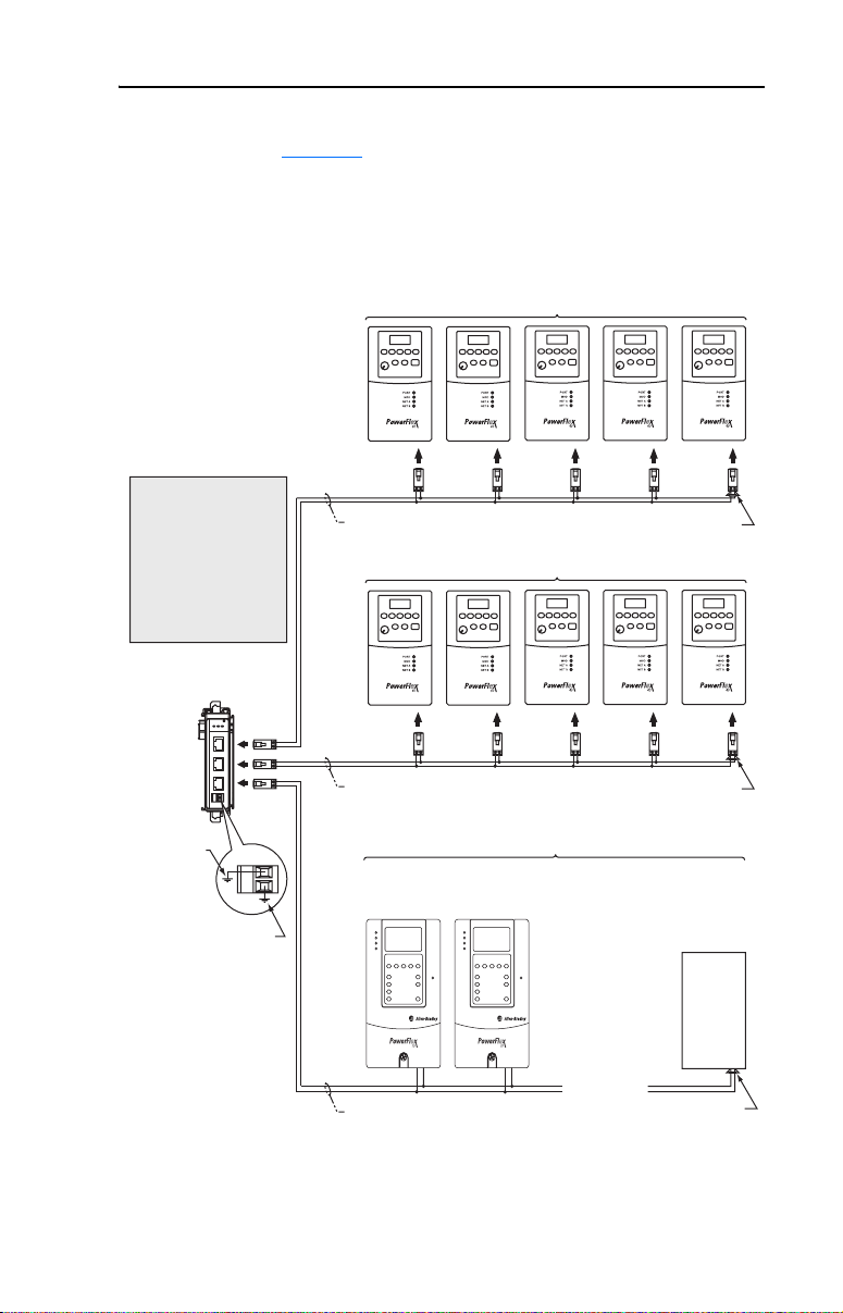
In Multi-Drive mode, any channel can be configured for “RTU Master”
operation (Figure 1.4). This enables connection of up to 31 RTU Slave
devices, such as PowerFlex 7-Class drives with 20-COMM-H RS485
HVAC adapters.
Figure 1.4 Multi-Drive Mode and Modbus RTU Master Mode Wiring Example
CH1 - Multi-Drive Mode (up to 5 PowerFlex 4-Class Drives)
AK-U0-RJ45-TB2P
Terminal Block
Wiring Tip:
The 1769-SM2 has an
integral terminating
resistor for each channel.
Thus, it is only necessary
to connect a terminating
resistor to the RJ45
terminal block at the last
drive on each channel.
CH1
CH2
CH3
1769-SM2
Module
MODULE
CH1
CH2 CH3
C
H
1
C
H
2
C
H
3
Connectors
User-Supplied Wire (recommend
Belden No. 3105A or equivalent)
CH2 - Multi-Drive Mode (up to 5 PowerFlex 4-Class Drives)
AK-U0-RJ45-TB2P
Terminal Block
Connectors
User-Supplied Wire (recommend
Belden No. 3105A or equivalent)
Terminating Resistor
Terminating Resistor
120 ohm, ¼ Watt
120 ohm, ¼ Watt
Earth Ground
Connection
Ground Wire Connection
(for network
communication
cable shielding)
CH3 - Modbus RTU Master Mode (up to 31 Devices)
PowerFlex 7-Class Drives
with 20-COMM-H RS485 HVAC
Communication Adapters
. . .
User-Supplied Wire (recommend
Belden No. 3105A or equivalent)
Terminating Resistor
Generic
Modbus RTU
Device
120 ohm, ¼ Watt
Page 18

1-6 Getting Started
Benefits of Multi-Drive mode include:
• Lower hardware costs. Only one 1769-SM2 is needed for up to five
PowerFlex 4-Class drives per channel (15 total).
• Controller can independently control, monitor, and read/write
parameters for all five drives on each channel (same functionality as
Single mode).
The trade-offs of Multi-Drive mode include:
• Since the RS-485 ports are used for daisy-chaining the drives,
additional DSI peripheral devices cannot be used with the drives.
This includes an optional, external PowerFlex 4-Class HIM
(22-HIM-A3 or 22-HIM-C2S) or a 22-SCM-232 Serial Converter
module with a software tool. The AK-U0-RJ45-SC1 DSI Splitter
cable cannot be used to add a second connection for a DSI peripheral
device.
Compatible Products
The 1769-SM2 module is compatible with Allen-Bradley PowerFlex
4-Class (Component class) drives and other products that support DSI.
At the time of publication, compatible products include:
• PowerFlex 4 drives
• PowerFlex 4M drives
• PowerFlex 40 drives
• PowerFlex 40P drives
• PowerFlex 400 drives
When the 1769-SM2 is used in Multi-Drive as a Modbus RTU Master,
other Modbus RTU Slave devices, such as PowerFlex 7-Class drives
with 20-COMM-H RS485 HVAC adapters, can also be connected.
Required Equipment
Equipment Shipped with the Module
When you unpack the module, verify that the package includes:
❑ One 1769-SM2 module
❑ This manual
Page 19
Getting Started 1-7
User-Supplied Equipment
To install and configure the 1769-SM2 module, you must supply:
❑ A small flathead screwdriver
❑ Communications cable 22-RJ45CBL-C20
- orAK-U0-RJ45-TB2P terminal block connectors (one for each
channel connection and one for each drive connection) and twisted
pair network wiring (Belden No. 3105A or equivalent)
❑ Configuration tool, such as:
– PowerFlex 4-Class HIM (22-HIM-A3 or 22-HIM-C2S)—
required to access module parameters if not using DriveExplorer
software or DriveExecutive software
– DriveExplorer (version 3.01 or higher)
– DriveExecutive stand-alone software (version 4.01 or higher) or
bundled with the DriveTools SP suite (version 4.01 or higher)
– RSNetWorx for DeviceNet
❑ Controller configuration software (such as RSLogix 500/5000)
Safety Precautions
Please read the following safety precautions carefully.
ATTENTION: Risk of injury or death exists. The PowerFlex drive
may contain high voltages that can cause injury or death. Remove all
!
power from the PowerFlex drive, and then verify power has been
removed before installing or removing the module.
ATTENTION: Risk of injury or equipment damage exists. Only
personnel familiar with drive and power products and the associated
!
machinery should plan or implement the installation, start-up,
configuration, and subsequent maintenance of the product using the
module. Failure to comply may result in injury and/or equipment
damage.
ATTENTION: Risk of injury or equipment damage exists. If the
module is transmitting control I/O to the drive, the drive may fault when
!
you reset the module. Determine how your drive will respond before
resetting the module.
ATTENTION: Risk of injury or equipment damage exists. When a
system is configured for the first time, there may be unintended or
!
incorrect machine motion. Disconnect the motor from the machine or
process during initial system testing.
Page 20

1-8 Getting Started
ATTENTION: Risk of injury or equipment damage exists.
Parameters 04 - [Idle Action 1], 19 - [Idle Action 2], and 34 - [Idle
!
Action 3] let you determine the action of the module and connected
drives if communications are disrupted. By default, these parameters
fault the drive. You can set these parameters so that the drive continues
to run. Precautions should be taken to ensure that the settings of these
parameters do not create a risk of injury or equipment damage. When
commissioning the drive, verify that your system responds correctly to
various situations (for example, a disconnected cable or a faulted
controller).
ATTENTION: Risk of injury or equipment damage exists. The
examples in this publication are intended solely for purposes of
!
example. There are many variables and requirements with any
application. Rockwell Automation, Inc. does not assume responsibility
or liability (to include intellectual property liability) for actual use of
the examples shown in this publication.
ATTENTION: This equipment is intended for use in a Pollution
Degree 2 industrial environment, in overvoltage Category II
!
applications (as defined in IEC publication 60664-1), at altitudes up to
2000 meters without derating.
This equipment is considered Group 1, Class A industrial equipment
according to IEC/CISPR Publication 11. Without appropriate
precautions, there may be potential difficulties ensuring
electromagnetic compatibility in other environments due to conducted
as well as radiated disturbance.
This equipment is supplied as “open type” equipment. It must be
mounted within an enclosure that is suitably designed for those specific
environmental conditions that will be present and appropriately
designed to prevent personal injury resulting from accessibility to live
parts. The interior of the enclosure must be accessible only by the use
of a tool. Subsequent sections of this publication may contain
additional information regarding specific enclosure type ratings that are
required to comply with certain product safety certifications.
See NEMA Standards publication 250 and IEC publication 60529, as
applicable, for explanations of the degrees of protection provided by
different types of enclosure. Also, see the appropriate sections in this
publication, as well as the Allen-Bradley publication 1770-4.1
(“Industrial Automation Wiring and Grounding Guidelines”), for
additional installation requirements pertaining to this equipment.
Page 21

Getting Started 1-9
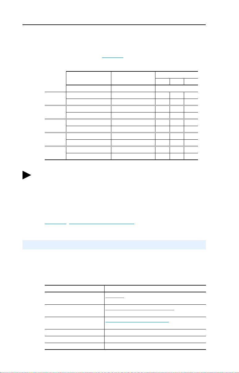
Quick Start
This section is provided to help experienced users quickly start using the
1769-SM2 Compact I/O to DSI module. If you are unsure how to
complete a step, refer to the referenced chapter.
Step Action Refer to…
1 Review the safety precautions for the module. Throughout This Manual
2 Verify that the drive is properly installed. Drive User Manual
3 Install the module.
Verify that the controller is not powered. Connect the
module to the controller backplane bus. Then connect
the module to the drive(s) using communications cable
22-RJ45CBL-C20 or AK-U0-RJ45-TB2P terminal block
connectors and communications network wiring.
4 Apply power to the module.
The module receives power from the controller. Apply
power to the controller. The MODULE indicator should
be green or flashing green. If it flashes red, there is a
problem. Refer to Chapter
5 Configure the module for your application.
Set the following parameters for the module as required
by your application:
• I/O configuration.
• Fault actions.
6 Apply power to the drive. Drive User Manual
7 Configure the controller to communicate with the
module.
8 Create a ladder logic program.
Use a programming tool such as RSLogix to create a
ladder logic program that enables you to:
• Control the module and connected drive.
• Monitor or configure the drive using Explicit
Messages.
9, Troubleshooting.
Chapter
2,
Installing the Module
3,
Chapter
Configuring the Module
Depending on the type of
controller and 1769-SM2
operating mode:
• Chapter
• Chapter 7,
• Chapter 8,
6,
MicroLogix 1500
Example Ladder
Programs
CompactLogix
Example Ladder
Programs
ControlLogix w/
1769-ADN DeviceNet
Example Ladder
Program
Page 22
1-10 Getting Started
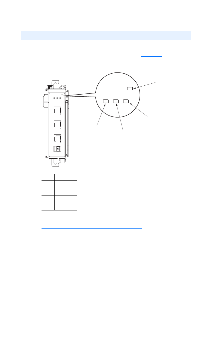
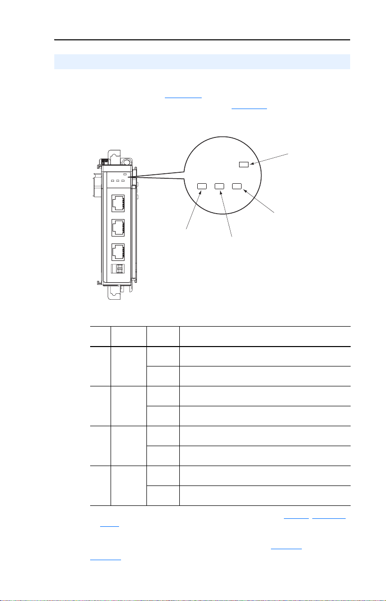
Status Indicators
The module uses four status indicators to report its operating status.
They can be viewed on the front of the module (Figure 1.5
Figure 1.5 Status Indicators
MODULE
CH1
CH2 CH3
DSI
C
H
1
C
H
2
C
H
3
Item Name
MODULE
➊
CH1
➋
CH2
➌
CH3
➍
).
➊
MODULE
CH1
CH2
CH3
➋
➍
➌
After installing the module and applying power to the drive(s), refer to
Viewing Start-Up Status Indicators
status indications and their descriptions.
on page 2-15 for possible start-up
Page 23

Chapter 2
Installing the Module
This chapter provides instructions for installing the 1769-SM2 as an
expansion I/O module on MicroLogix 1500 and CompactLogix
controllers, or with a remote 1769-based adapter.
Topic Page
Preparing for an Installation
Removing Power 2-2
Setting the Configuration Mode Switch 2-3
Setting the Operating Mode Switch (Single/Multi-Drive) 2-4
Assembling the Module to the Controller 2-5
Mounting the Module 2-6
Replacing the Module within a System 2-9
Connecting Drive(s) to the Module 2-10
Grounding the Module 2-12
Network Cable Strain Relief 2-14
Applying Power 2-14
Viewing Start-Up Status Indicators 2-15
2-1
Preparing for an Installation
Consider the following when installing the 1769-SM2 module:
• Verify that you have all required equipment. Refer to Required
Equipment on page 1-6.
• A MicroLogix 1500 Base Unit or Compact I/O power supply has
limits in the amount of +5V dc and +24V dc current it can supply to
modules in its I/O bank. These limits depend on the catalog number
(e.g. 1769-PA2) of the power supply. A bank of modules must not
exceed the current limits of the MicroLogix 1500 Base Unit or I/O
bank power supply.
Refer to the MicroLogix 1500 User Manual (publication
1764-UM001) or the Compact 1769 Expansion I/O Power Supplies
Installation Instructions (publication 1769-5.14).
• The module has a distance rating of four. Therefore, the module must
be within four modules of the I/O bank’s power supply.
Page 24

2-2 Installing the Module
ATTENTION: Risk of equipment damage exists. The 1769-SM2
module contains ESD (Electrostatic Discharge) sensitive parts that can
!
be damaged if you do not follow ESD control procedures. Static control
precautions are required when handling the module. If you are
unfamiliar with static control procedures, refer to Guarding Against
Electrostatic Damage (publication 8000-4.5.2).
Removing Power
ATTENTION: Risk of equipment damage exists. Remove power
before installing or removing the 1769-SM2 module. When you install
!
or remove the module with power applied, an electrical arc may occur.
An electrical arc can cause personal injury or equipment damage by:
• Sending an erroneous signal to your system’s field devices, causing
unintended machine motion.
• Causing an explosion in a hazardous environment.
Electrical arcing causes excessive wear to contacts on both the module
and its mating connector. Worn contacts may create electrical
resistance.
Page 25
Installing the Module 2-3
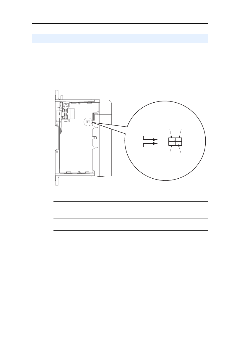
Setting the Configuration Mode Switch
Before installing the module, make sure its Configuration Mode Switch
is correctly set. See Configuration Methods on page 3-3 for details on
the Controller and Parameter configuration modes. Then set the
Configuration Mode Switch (SW1 in Figure 2.1
Figure 2.1 Configuration Mode and Single/Multi-Drive Operation Switch Locations
) for your application.
SW1 Setting Description
CONT (Controller)
back position
PARAM (Parameter)
front position
Default setting—The 1769-SM2 module uses the configuration
data downloaded from the controller on power-up and when the
controller is placed in run mode.
The 1769-SM2 module uses its internal parameter settings to
configure the module.
Configuration
Mode Switch
(SW1)
Operating
Mode Switch
(SW2)
(Controller
Position)
CONT PARAM
(Single
Position)
(Parameter
Position)
1X 5X
(Multi-Drive
Position)
Page 26

2-4 Installing the Module
Setting the Operating Mode Switch (Single/Multi-Drive)
Before installing the module, set its Operating Mode Switch (SW2 in
Figure 2.1) for Single or Multi-Drive operation. All channels (CH1,
CH2, and CH3) will operate in the selected mode.
SW2 Setting Description
1X (Single mode)
back position
5X (Multi-Drive mode)
front position
Default setting — sets the 1769-SM2 module for Single mode
using a single drive connection (one drive per channel).
Important: In Single mode, only one drive can be connected per
channel. Connections to multiple drives must be removed since
all powered and connected hosts will respond to any message
sent by the module.
Sets the 1769-SM2 module for Multi-Drive mode using up to five
PowerFlex 4-Class drives per channel.
In Multi-Drive mode, DSI peripherals such as the 22-HIM-A3 /
-C2S Human Interface Module, 22-SCM-232 serial converter, etc.
CANNOT be used. They will not operate with the 1769-SM2
module or drives.
The specific number of drives used in Multi-Drive mode for each
channel and a unique address for each drive must be configured
using 1769-SM2 module parameters. For instructions, see
Setting the I/O Configuration (Multi-Drive Mode Only)
page 3-14 and Setting Drive Node Addresses (Multi-Drive Mode
Only) on page 3-16.
NOTE: In Multi-Drive mode, each channel can be independently
configured for Modbus RTU Master operation by setting the
respective channel’s [DSI I/O Cfg] parameter to “5” (RTU Master).
This enables up to 31 RTU slave devices, such as PowerFlex
7-Class drives with 20-COMM-H RS485 HVAC adapters to be
connected to that channel.
on
Important: A new switch setting is recognized only when power is
applied to the module, or the module is reset. If you change
a setting, cycle power or reset the module.
The Configuration Mode Switch (SW1) and Operating Mode Switch
(SW2) settings can be verified by respectively viewing module
Parameters 01 - [Config Mode] and 02 - [DSI Mode] using an
optional, external PowerFlex 4-Class HIM, DriveExplorer software or
DriveExecutive software.
Page 27

Installing the Module 2-5
Assembling the Module to the Controller
The 1769-SM2 module can be attached to adjacent controller modules
before or after mounting. For mounting instructions, see Panel
Mounting on page 2-6 or DIN Rail Mounting on page 2-8. To work with
a system that is already mounted, see Replacing the Module within a
System on page 2-9.
Figure 2.2 and the following procedure describes how to assemble the
Compact I/O system.
Figure 2.2 Assembling 1769-SM2 Module to Compact I/O System
A
C
B
D
E
B
F
1. Disconnect power.
2. Check that the bus lever (A) of the 1769-SM2 module is in the
unlocked (fully right) position.
3. Use the upper and lower tongue-and-groove slots (B) to secure the
modules together.
4. Move the 1769-SM2 module back along the tongue-and-groove slots
until the bus connectors (C) line up with each other.
5. Use your fingers or a small screwdriver to push the bus lever back
slightly to clear the positioning tab (D).
6. Move the 1769-SM2 module’s bus lever fully to the left (E) until it
clicks. Ensure it is locked firmly in place.
G
ATTENTION: Risk of equipment damage exists. When attaching the
1769-SM2 module to a Compact I/O system, it is very important that
!
the bus connectors are securely locked together to ensure proper
electrical connection. Failure to do this may cause an electrical arc,
which can cause personal injury or equipment damage.
Page 28
2-6 Installing the Module
7. Attach an end cap terminator (F) to the last module in the system by
using the tongue-and-groove slots as before.
8. Lock the end cap bus terminator (G).
Important: A 1769-ECR or 1769-ECL right or left end cap must be
Mounting the Module
ATTENTION: Risk of equipment damage exists. During panel or
DIN rail mounting of all devices, be sure that all debris (metal chips,
!
wire strands, etc.) is kept from falling into the 1769-SM2 module.
Debris that falls into the module could cause damage on power up.
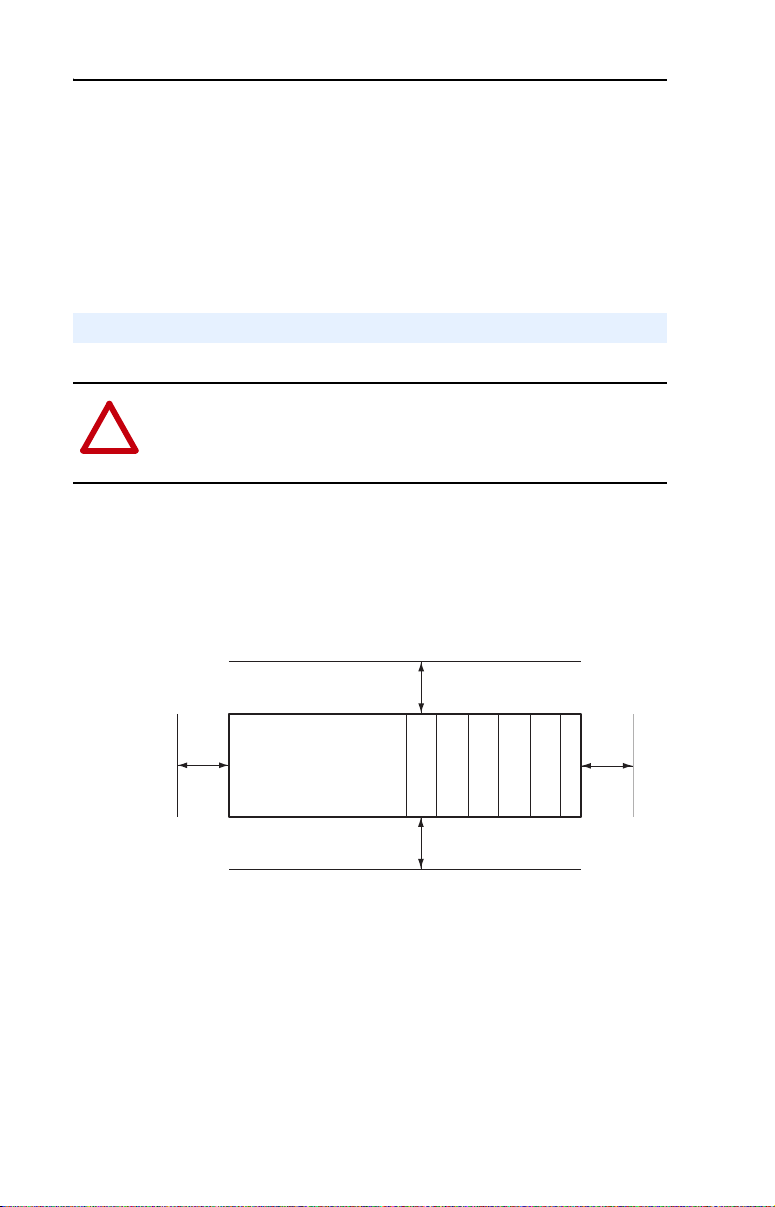
Minimum Spacing
Maintain spacing from enclosure walls, wireways, adjacent equipment,
etc. Allow 50 mm (2 in.) of space on all sides for adequate ventilation as
shown:
used to terminate the end of the serial communication
bus.
To p
Side
Allow at least 140 mm (5.5 in.) of enclosure depth to accommodate the
1769-SM2 module.
Panel Mounting
Mount the 1769-SM2 module to a panel using two screws per module.
Use M4 or #8 panhead screws (not included). Mounting screws are
required on every module.
Controller
Compact I/O
Compact I/O
Compact I/O
Bottom
Compact I/O
Compact I/O
End Cap or Cable
Side
Page 29
Installing the Module 2-7
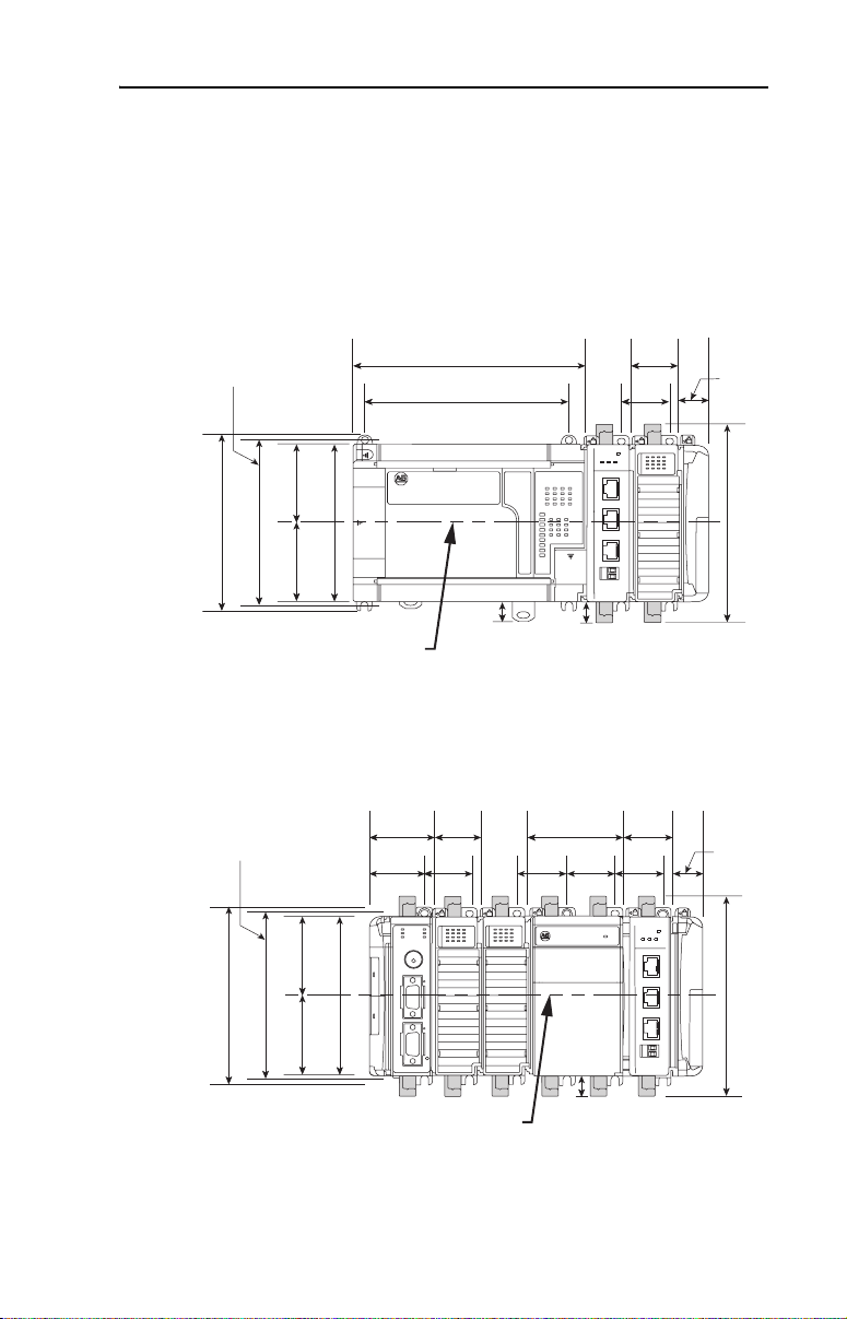
Panel Mounting Using the Dimensional Drawing
NOTE: All dimensions are in mm (inches). Hole spacing tolerance is
±0.4 mm (0.016 in.).
Figure 2.3 1769-SM2 Module with MicroLogix 1500 Base Unit and Processor
Mounting Hole
Dimension
132 mm (5.19 in)
122.6 mm (4.83 in)
59 mm
59 mm
(2.32 in)
(2.32 in)
118 mm (4.65 in)
168 mm
(6.62 in)
147 mm
(5.79 in)
ANport
PI / SC
D
C
H
1
C
H
2
C
H
3
DIN Rail
Center Line
13.5 mm
(0.53 in)
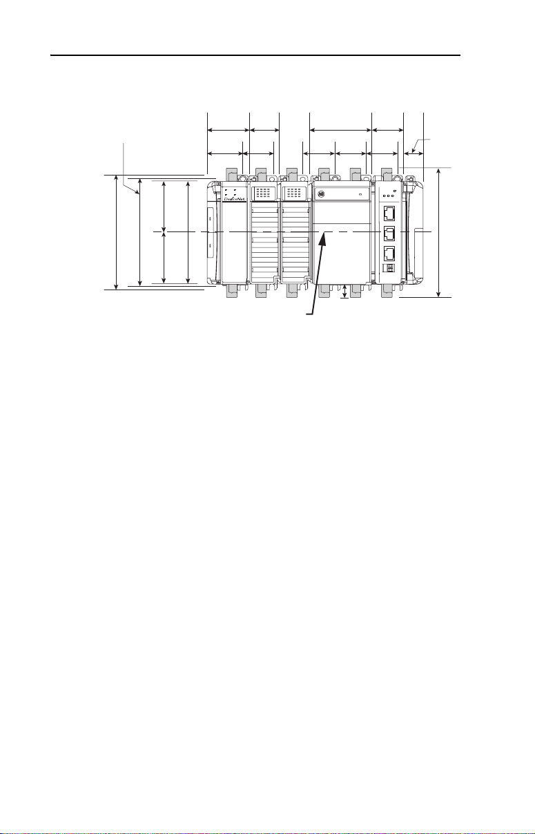
Figure 2.4 1769-SM2 Module with CompactLogix Controller
35 mm
Mounting Hole
Dimension
50 mm
(1.97 in)
40 mm
(1.58 in)
(1.38 in)
35 mm
(1.38 in)
(2.76 in)
35 mm
(1.38 in)
14.7 mm
(0.58 in)
70 mm
35 mm
(1.38 in)
59 mm
(2.32 in)
132 mm (5.19 in)
122.6 mm (4.83 in)
118 mm (4.65 in)
59 mm
(2.32 in)
CH1
MODULE
CH2
CH3
35 mm
(1.38 in)
35 mm
(1.38 in)
35 mm
(1.38 in)
35 mm
(1.38 in)
MODULE
ort
CH1
CH2
DPI / SCANp
C
H
1
C
H
2
C
H
3
28.5 mm
(1.12 in)
147.4 mm (5.81 in)
28.5 mm
(1.12 in)
CH3
147.4 mm (5.81 in)
DIN Rail
Center Line
14.7 mm
(0.58 in)
Page 30
2-8 Installing the Module
Figure 2.5 1769-SM2 Module with Remote 1769-Based Adapter
35 mm
(1.38 in)
35 mm
(1.38 in)
35 mm
(1.38 in)
port
CH1
N
A
C
I / S
P
D
C
H
1
C
H
2
C
H
3
28.5 mm
(1.12 in)
MODULE
CH2
CH3
147.4 mm (5.81 in)
Mounting Hole
Dimension
132 mm (5.19 in)
122.6 mm (4.83 in)
59 mm
59 mm
(2.32 in)
(2.32 in)
50 mm
(1.97 in)
40 mm
(1.58 in)
MS
IO
118 mm (4.65 in)
35 mm
(1.38 in)
35 mm
(1.38 in)
NS
DIAG
DIN Rail
Center Line
70 mm
(2.76 in)
35 mm
(1.38 in)
14.7 mm
(0.58 in)
Panel Mounting Procedure Using Module as a Template
The following procedure enables you to use the assembled modules as a
template for drilling holes in the panel. Due to module mounting hole
tolerance, it is important to follow these steps:
1. On a clean work surface, assemble no more than three modules.
2. Using the assembled modules as a template, carefully mark the
center of all module-mounting holes on the panel.
3. Return the assembled modules to the clean work surface, including
any previously mounted modules.
4. Drill and tap the mounting holes for the recommended M4 or #8
screw (not included).
5. Place the modules back on the panel, and check for proper hole
alignment.
6. Attach the modules to the panel using the mounting screws.
DIN Rail Mounting
The 1769-SM2 module can be mounted using these DIN rails:
• 35 x 7.5 mm (EN 50 022 - 35 x 7.5)
• 35 x 15 mm (EN 50 022 - 35 x 15)
When mounting the module to a DIN rail, make sure that the latches are
closed and properly securing the module.
Page 31

Installing the Module 2-9
Replacing the Module within a System
The 1769-SM2 module can be replaced while the system is mounted to a
panel (or DIN rail).
ATTENTION: Risk of equipment damage exists. Remove power
before installing or removing the 1769-SM2 module. When you install
!
or remove the module with power applied, an electrical arc may occur.
An electrical arc can cause personal injury or equipment damage by:
• Sending an erroneous signal to your system’s field devices, causing
unintended machine motion.
• Causing an explosion in a hazardous environment.
Electrical arcing causes excessive wear to contacts on both the module
and its mating connector. Worn contacts may create electrical
resistance.
1. Remove power.
2. Unplug the communications cable from each port (CH1, CH2, CH3)
on the 1769-SM2 module. Note each drive and the port to which it is
connected.
3. Remove the upper and lower mounting screws from the module (or
open the DIN latches using a flat-blade screwdriver).
4. On the right-side adjacent module, move its bus lever to the right
(unlock) to disconnect it from the module being removed.
5. Gently slide the disconnected 1769-SM2 module forward.
If you feel excessive resistance, make sure that you disconnected the
module from the bus and that you removed both mounting screws (or
opened the DIN latches).
TIP: It may be necessary to rock the module slightly from front to
back to remove it or, in a panel-mounted system, to loosen the screws
of adjacent modules.
6. Before installing the replacement 1769-SM2 module, be sure that the
bus lever on the right-side adjacent module is in the unlocked (fully
right) position.
7. Slide the replacement 1769-SM2 module into the open slot.
Page 32

2-10 Installing the Module
8. Connect the 1769-SM2 module and adjacent modules together by
locking (fully left) the bus levers on the 1769-SM2 module and the
right-side adjacent module.
9. Replace the mounting screws (or snap the module onto the DIN rail).
10. Plug the appropriate communications cable into its respective port on
the 1769-SM2 module.
11. Restore 1769-SM2 module configuration using an appropriate
configuration tool.
Connecting Drive(s) to the Module
NOTE: For Single or Multi-Drive mode, there is a maximum cable
distance limit per channel. See DSI Cable Requirements
more information.
For network wiring diagram examples, see the following figures:
1769-SM2 Operating Mode
Single mode (Default) Figure 1.2
Multi-Drive mode Figure 1.3
Multi-Drive mode with Modbus RTU Master Figure 1.4
on page A-2 for
Network Wiring
Diagram Example…
Single Mode
When the 1769-SM2 module is operated in Single drive mode, each
drive is directly connected to a channel port (CH1, CH2 or CH3) on the
module. Use either a 22-RJ45CBL-C20 communications cable for each
channel or AK-U0-RJ45-TB2P terminal block connectors and twisted
pair network wiring (Belden No. 3105A or equivalent).
Important: When connecting a drive to the channel port using
AK-U0-RJ45-TB2P terminal block connectors and twisted
pair network wiring, the following drive parameters MUST
be configured to the settings shown so that the 1769-SM2
module will communicate with the drive:
Drive Parameter Setting
A103 - [Comm Data Rate] “4” (19.2K)
A107 - [Comm Format] “0” (RTU 8-N-1)
Changes to these drive parameters require the drive to be
reset for the new settings to take effect.
Page 33

Installing the Module 2-11
When connecting a drive to the channel port using 22-RJ45CBL-C20
communications cable, the above drive parameters do not require
configuration because the drive senses that a DSI peripheral is connected
and it ignores these parameter settings.
Multi-Drive Mode
For Multi-Drive mode, each channel port MUST be connected to the
drives via daisy-chaining using AK-U0-RJ45-TB2P terminal block
connectors (one for the port connection and one for each drive
connection) and twisted pair network wiring (Belden No. 3105A or
equivalent). The 22-RJ45CBL-C20 communications cable and splitter
cables cannot be used.
Important: The following drive parameters MUST be configured to the
settings shown so that the 1769-SM2 module will
communicate with the drives:
Drive Parameter Setting
A103 - [Comm Data Rate] “4” (19.2K)
A104 - [Comm Node Addr] Value of Drive Addr x parameter in the
1769-SM2
A107 - [Comm Format] “0” (RTU 8-N-1)
Changes to these drive parameters require the drive to be
reset for the new settings to take effect.
Page 34
2-12 Installing the Module
Grounding the Module
The 1769-SM2 module is intended to be mounted to a well-grounded
mounting surface such as a metal panel. Additional grounding
connections from the module’s mounting tabs or DIN rail (if used) are
not required unless the mounting surface cannot be grounded. Refer to
Industrial Automation Wiring and Grounding Guidelines, publication
1770-4.1, for additional information.
Shielded Connector Grounding Requirements
When using the 22-RJ45CBL-20 cable, which has shielded connectors,
the shields are all grounded to the chassis terminal block on the
1769-SM2 module (item 11 in Figure 1.1
• Install a wire from the chassis terminal block on the 1769-SM2
module to a grounded, conductive surface (i.e. metal panel). See
Figure 2.6
• Remove the shield connection to chassis ground at the drive I/O
block shield terminal.
Drive Drive I/O Block
PowerFlex 4 Terminal 16
PowerFlex 4M Terminal 16
PowerFlex 40 Terminal 19
PowerFlex 40P Terminal 19
PowerFlex 400 Terminal 20
.
). However, the user must:
Figure 2.6 Shielded Connector Grounding Details
MODULE
CH1
CH2 CH3
DSI / Modbus RTU
C
H
1
C
H
2
C
H
3
To Drive 1
To Drive 2
To Drive 3
Page 35
Installing the Module 2-13
Unshielded Connector Grounding Requirements
When using twisted pair network wiring with unshielded
AK-U0-RJ45-TB2P connectors, ground the RJ45 socket on the drive by
connecting the drive chassis ground power terminal to the I/O block
shield terminal.
Drive Drive I/O Block
PowerFlex 4 Terminal 16
PowerFlex 4M Terminal 16
PowerFlex 40 Terminal 19
PowerFlex 40P Terminal 19
PowerFlex 400 Terminal 20
The 1769-SM2 module’s RJ45 connectors (CH1, CH2, and CH3), which
are electrically common, should be grounded by attaching a drain wire
from the 1769-SM2 terminal block (item 11 in Figure 1.1
conductive surface (i.e. metal panel). If shielded cable (not required) is
used, the cable shield should also be connected to the chassis by
attaching the cable shield to the 1769-SM2 terminal block (Figure 2.7
Good wiring practice dictates that the cable shield be terminated to the
chassis at only one point along the cable to prevent ground loops from
occurring. The chassis terminal block on the 1769-SM2 module is
provided as a convenient place for this termination.
) to a grounded,
).
Figure 2.7 Unshielded Connector Grounding Details
To Drive 1 To Drive 2
MODULE
CH1
CH2 CH3
To Drive 1 To Drive 2
To Drive 1 To Drive 2
DSI / Modbus RTU
C
H
1
C
H
2
C
H
3
. . .
. . .
. . .
Page 36

2-14 Installing the Module
Network Cable Strain Relief
Some type of strain relief should be provided for the communication
cables within 12 inches (305 mm) of the 1769-SM2 module. This may
include wireways, cable ties, panel mounted strain reliefs, or some other
appropriate strain relief device.
Applying Power
ATTENTION: Risk of equipment damage, injury, or death exists.
Unpredictable operation may occur if you fail to verify that parameter
!
settings are compatible with your application. Verify that settings are
compatible with your application before applying power to the drive.
1. Apply power to the controller. The status indicators can be viewed on
the front of the 1769-SM2 module after power has been applied.
2. Apply power to the drive(s). When you apply power to the
1769-SM2 module, controller, and drives for the first time, the status
indicators should be green after an initialization. If the status
indicators go red, there is a problem. Refer to Chapter 9
Troubleshooting.
,
Page 37
Installing the Module 2-15
Viewing Start-Up Status Indicators
Status indicators for the communication module can be viewed on the
front of the module (Figure 2.8
start-up status indications are shown in Table 2.A.
Figure 2.8 Module Status Indictors
) after power has been applied. Possible
➊
MODULE
CH1
CH2 CH3
DSI
C
H
1
C
H
2
C
H
3
MODULE
CH1
CH2
CH3
➋
➍
➌
Table 2.A Module Start-Up Status Indications
Status
Item
Indicator
MODULE Green Normal Operation. The module has established
➊
CH1 Green Normal Operation. CH1 is operating and is transferring I/O
➋
CH2 Green Normal Operation. CH2 is operating and is transferring I/O
➌
CH3 Green Normal Operation. CH3 is operating and is transferring I/O
➍
(1)
If all status indicators are off, the module is not receiving power. Refer to Chapter 2, Installing the
Module, for instructions on installing the module.
Status
Flashing
Green
Flashing
Green
Flashing
Green
Flashing
Green
(1)
Description
communications with the controller.
The module is establishing communications with the
controller.
data between the controller and the drive(s).
Normal Operation. CH1 is operating but is not transferring
I/O data between the controller and the drive(s).
data between the controller and the drive(s).
Normal Operation. CH2 is operating but is not transferring
I/O data between the controller and the drive(s).
data between the controller and the drive(s).
Normal Operation. CH3 is operating but is not transferring
I/O data between the controller and the drive(s).
For more details on status indicator operation, see page 9-2 and
page 9-3.
Page 38

2-16 Installing the Module
Notes:
Page 39

Chapter 3
Configuring the Module
This chapter provides instructions and information for setting the
parameters in the 1769-SM2 module.
Topic Page
Determining I/O Image Size
Configuration Tools 3-2
Configuration Methods 3-3
Controller Mode 3-3
Parameter Mode 3-12
Using the Optional, External PowerFlex 4-Class HIM 3-13
Setting the I/O Configuration (Multi-Drive Mode Only) 3-14
Setting an Idle Action (Single and Multi-Drive Mode) 3-15
Setting Drive Node Addresses (Multi-Drive Mode Only) 3-16
Configuring the Modbus RTU Master Parameters 3-17
Resetting the Module 3-20
Viewing the Module Status Using Parameters 3-21
Flash Updating the Module 3-22
3-1
For a list of parameters, refer to Appendix
definitions of terms in this chapter, refer to the Glossary
Determining I/O Image Size
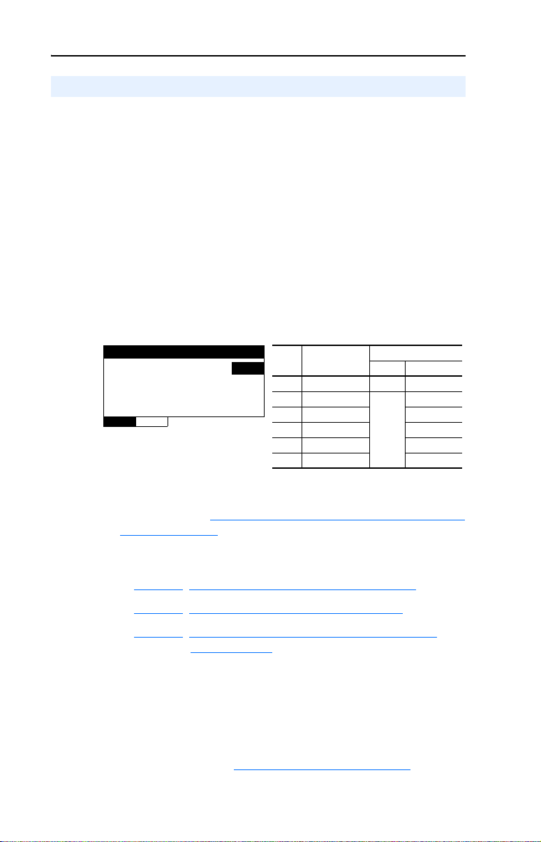
Single Mode
When the module is in Single mode, the I/O image is comprised of a
maximum of 7 words (Table 3.A
Table 3.A I/O Image Table for Single Mode
Output Image Input Image
Module Control Word Module Status Word 0
Logic Command Logic Status 1 3 5
Reference Feedback 2 4 6
TIP: When using Single mode, it is recommended to set the I/O size to
7 Input words and 7 Output words. This accommodates one drive per
channel, even if a channel is left unused for future use.
).
B, Module Parameters. For
.
Wor d
CH1 CH2 CH3
Page 40
3-2 Configuring the Module
Multi-Drive Mode
When the module is in Multi-Drive mode, the I/O image is comprised of
a maximum of 31 words (Table 3.B).
Table 3.B I/O Image Table for Multi-Drive Mode
Output Image Input Image
Module Control Word Module Status Word 0
Drive 0
Drive 1
Drive 2
Drive 3
Drive 4
TIP: When using Multi-Drive mode, it is recommended to set the I/O
size to 31 Input words and 31 Output words. This accommodates up to 5
drives per channel, even if a channel is left unused for future use.
Configure a smaller I/O size only if there is a limited amount of I/O
available on a controller.
Logic Command Logic Status 1 11 21
Reference Feedback 2 12 22
Logic Command Logic Status 3 13 23
Reference Feedback 4 14 24
Logic Command Logic Status 5 15 25
Reference Feedback 6 16 26
Logic Command Logic Status 7 17 27
Reference Feedback 8 18 28
Logic Command Logic Status 9 19 29
Reference Feedback 10 20 30
Word
CH1 CH2 CH3
For additional information on configuring the I/O image size, refer to
Chapter
4, Understanding the I/O Image.
Configuration Tools
The 1769-SM2 module stores parameters and other information in its
own non-volatile memory. You must, therefore, access the module to
view and edit its parameters. The following tools can be used to access
the module parameters:
Tool Refer to…
PowerFlex 4-Class HIM
(22-HIM-A3 or 22-HIM-C2S)
DriveExplorer Software
(version 3.01 or higher)
DriveExecutive Software
(version 4.01 or higher)
RSLogix 500 LG500-GR001
RSLogix 5000 9399-RLD300GR
RSNetWorx for DeviceNet DNET-GR001
Page 3-13
http://www.ab.com/drives/driveexplorer, or
DriveExplorer online help (installed with the software)
http://www.ab.com/drives/drivetools
DriveExecutive online help (installed with the software)
, or
Page 41

Configuring the Module 3-3
Configuration Methods
The 1769-SM2 module has two methods of configuration, which are
determined by the Configuration Mode Switch (SW1 in Figure 2.1
• Controller mode—The 1769-SM2 uses the configuration data
downloaded from the controller on power-up and when the controller
is placed in run mode. The data is configured using RSLogix 500,
RSLogix 5000 or RSNetWorx for DeviceNet.
• Parameter mode—The 1769-SM2 uses its internal parameter settings
to configure the module. The data is configured using an optional,
external PowerFlex 4-Class HIM, DriveExplorer, or DriveExecutive.
Only one method can be selected, and it is used for all three channels.
):
Controller Mode
When the Configuration Mode Switch (SW1 in Figure 2.1
default CONT (Controller) position, the 1769-SM2 uses the configuration
data downloaded from the controller on power-up and when the controller
is placed in run mode. Depending on the controller, configuration data is
allocated and entered using RSLogix500 or RSLogix 5000.
Configuration Data
The 1769-SM2 module contains a set of 42 words of configuration data
that is used to configure the module's behavior (Table 3.C). A software
tool, such as RSLogix 500, RSLogix 5000 or RSNetWorx for DeviceNet
is used to read/write the configuration data.
Table 3.C 1769-SM2 Module Configuration Data
Parameter Name CH1 CH2 CH3
Idle Action Word 0 Word 14 Word 28
Flt Cfg Logic Word 1 Word 15 Word 29
Flt Cfg Ref Word 2 Word 16 Word 30
DSI I/O Cfg Word 3 Word 17 Word 31
Drive 0 Addr Word 4 Word 18 Word 32
Drive 1 Addr Word 5 Word 19 Word 33
Drive 2 Addr Word 6 Word 20 Word 34
Drive 3 Addr Word 7 Word 21 Word 35
Drive 4 Addr Word 8 Word 22 Word 36
RTU Baud Rate Word 9 Word 23 Word 37
RTU Format Word 10 Word 24 Word 38
RTU Rx Delay Word 11 Word 25 Word 39
RTU Tx Delay Word 12 Word 26 Word 40
RTU Msg Timeout Word 13 Word 27 Word 41
) is in the
Page 42

3-4 Configuring the Module
The configuration data directly correlates to the module parameters.
Refer to Appendix B for more information.
Entering MicroLogix 1500 Configuration Data Using RSLogix 500 Before v6.30
Earlier versions of RSLogix 500 can be used, but the configuration data
must be entered in raw form in a Data Config table following the format
in Table 3.C
recommended for use with the 1769-SM2 because it contains a dedicated
I/O configuration window for the module to simplify the configuration
process. Version 6.30 is also required to perform explicit messaging,
such as parameter reads/writes.
Entering MicroLogix 1500 Configuration Data Using RSLogix 500 v6.30 (or higher)
Allocate and enter the configuration data by performing these steps:
1. In the RSLogix 500 treeview, double-click on I/O Configuration to
open the I/O Configuration window. Double-click the 1769-SM2 in
the Current Cards Available list to add the module to the controller
system. Select the “1769-SM2” row and click the A
command button. The 1769-SM2 I/O Configuration window
(Figure 3.1
. However, RSLogix 500 v6.30 (or higher) is highly
) appears.
dv Config
Figure 3.1 I/O Configuration Window and Expansion General Configuration Screen
Page 43

Configuring the Module 3-5
2. Enter the Series letter of the 1769-SM2, which can be determined by
checking the data nameplate label on the module (item 9 in
Figure 1.1
The I/O image of the module can be up to 31 words of Input and 31
words of Output, depending on the mode selected (Single or
Multi-Drive) and the number of drives connected. A Single mode
system with one drive on each channel requires 7 Input words and 7
Output words. A Multi-Drive mode system with five drives on each
channel requires 31 Input words and 31 Output words. See Table 3.A
or Table 3.B to determine the number of Input Words and Output
Words to enter for your system.
The Extra Data Length field can only be set to a size of 0 or 42. If the
controller will contain the configuration data for download to the
1769-SM2 module (Configuration Mode Switch SW1 set to CONT
position), set this value to 42. If the configuration data will be
contained in the 1769-SM2 parameters (Configuration Mode Switch
SW1 set to PARAM position), this value should be set to 0. See
Table 3.C
Figure 3.2 Expansion General Configuration Tab Screen
).
for descriptions of these configuration words.
Page 44

3-6 Configuring the Module
3. Click on the Chan. 1 tab (Figure 3.3) and set the I/O Config data
area accordingly. In this example, the 1769-SM2 is configured to
fault if the controller is switched to Program mode, and one drive is
connected at node address 100.
Figure 3.3 Chan. 1 Tab Data Example Screen
Important: When using Multi-Drive mode, the node addresses
entered in the Drive Addr x fields must match the
corresponding drive Parameter 104 - [Comm Node
Addr] value in the PowerFlex 4-Class drives so that the
1769-SM2 module will communicate with the drives.
Note that the DSI Fault Config settings can only be accessed if the
Idle Action is set to “Send Flt Cfg” (Figure 3.4
).
Page 45

Configuring the Module 3-7
Figure 3.4 Chan. 1 Tab Data Screen with Idle Action - Send Flt Cfg Enabled
4. For each additional channel being used, select its respective tab, set
the desired I/O configuration, and enable the appropriate idle action.
TIP: Alternatively, data can be entered on the Generic Extra Data
Config tab (shown in Figure 3.5 for identification purposes only).
However, with the easy-to-use Chan.1, Chan. 2, and Chan. 3 tabs, there
is no need to enter data on the Generic Extra Data Config tab. But as a
useful reference, this tab does show how the controller stores the data in
the configuration words.
Figure 3.5 Generic Extra Data Config Tab Screen
Page 46

3-8 Configuring the Module
See Table 3.C for descriptions of these configuration words.
5. Click OK when finished. The MicroLogix 1500 will download the
configuration data to the 1769-SM2 module when the controller is
placed in run mode.
Special Case— Data Entry for 2 Stop Bits Communication
The Chan.1, Chan. 2, and Chan 3 tabs do not allow settings that specify 2
stop bits communication in Modbus RTU operation. For this type of
configuration, you must use the Generic Extra Data Config tab to enter
the data by performing these steps:
1. To configure a specific 1769-SM2 module channel for 2 stop bits
communication, click on the Generic Extra Data Config tab.
2. On the Generic Extra Data Config tab screen, enter the appropriate
values from Table 3.D
Figure 3.6 Entering Data for 2 Stop Bits on Generic Extra Data Config Screen
in the offset addresses highlighted in Figure 3.6.
Table 3.D Entry Data for 2 Stop Bits Communication
1769-SM2 CH Offset Address Value Description
110 3
4
5
224 3
4
5
338 3
4
5
Sets CH1 for 8-N-2 format
Sets CH1 for 8-E-2 format
Sets CH1 for 8-O-2 format
Sets CH2 for 8-N-2 format
Sets CH2 for 8-E-2 format
Sets CH2 for 8-O-2 format
Sets CH3 for 8-N-2 format
Sets CH3 for 8-E-2 format
Sets CH3 for 8-O-2 format
Page 47

Configuring the Module 3-9
3. Click OK to apply the changes and close the screen. However, if you
click Apply or leave this tab to go to another tab, you may see this
message dialog box. If so, click Ye s to apply the changes.
Entering CompactLogix Configuration Data Using RSLogix 5000 v10 (or higher)
Allocate and enter the configuration data by performing these steps:
1. In the RSLogix 5000 treeview, right-click on CompactBus Local
and select New Module.
Figure 3.7 Treeview Window with New Module Inset Screen
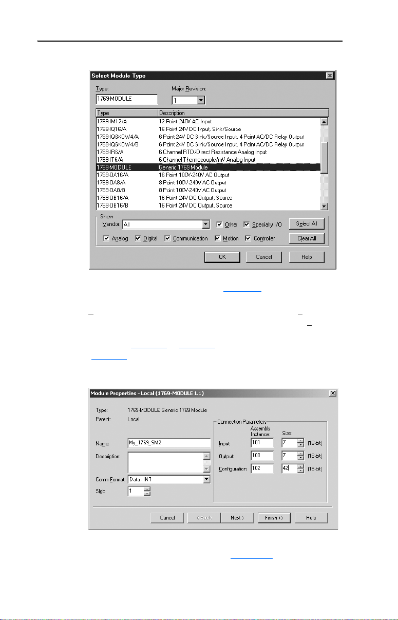
2. After the Select Module Type screen (Figure 3.8) appears, select the
1769-MODULE and click OK.
Page 48
3-10 Configuring the Module
Figure 3.8 Select Module Type Screen
3. After the Module Properties screen (Figure 3.9) appears, enter a
name for the module, such as “My_1769_SM2.” Change the Comm
ormat to “Data - INT,” which will enable the entry of Output
F
Connection parameters (no longer grayed out). Enter the Slo
location of the 1769-SM2. Enter the desired Input and Output word
length (see Table 3.A or Table 3.B) and Configuration data size
(Table 3.C
). Click Next >.
t
Figure 3.9 Module Properties Screen
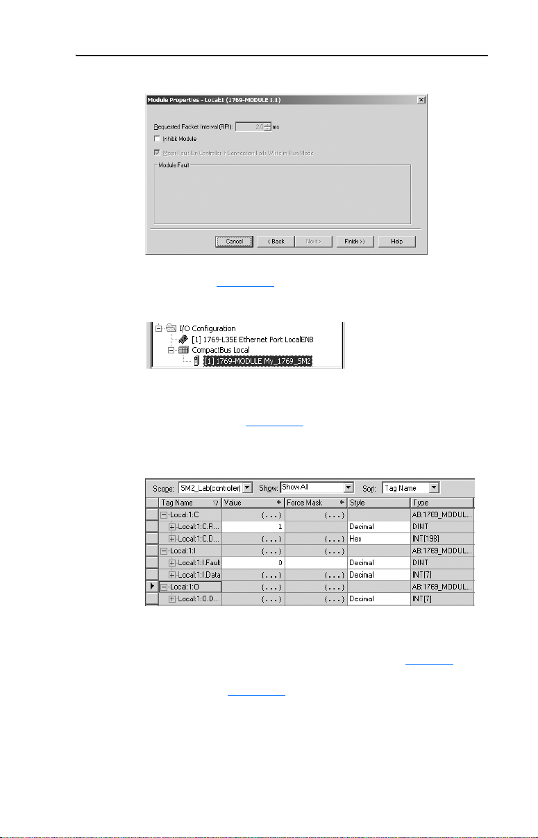
4. On the Module Properties last screen (Figure 3.10), click Finish >>.
Page 49
Configuring the Module 3-11
Figure 3.10 Module Properties Last Screen
5. The treeview (Figure 3.11) now shows the 1769-MODULE.
Figure 3.11 RSLogix 5000 Treeview with Listed 1769-MODULE
6. Double-clicking on the Controller Tags or Program Tags in the
treeview will display the various tags, including the tags for the
1769-SM2 module (Figure 3.12). Click on the Monitor Tags tab at
the bottom of the window to enter the configuration data.
Figure 3.12 Controller Tags Screen
NOTE: RSLogix 5000 may create a data array that is much larger than
the 42 words previously specified when the module was configured. Use
words 0…41 and ignore all other words (42+). Refer to Table 3.C for
configuration data words and parameter descriptions. Also note that the
data entry format in Figure 3.12
format, click on the appropriate field in the “Style” column.
The CompactLogix will download the configuration data to the
1769-SM2 module on power-up.
is hexadecimal (16#). To change the
Page 50
3-12 Configuring the Module
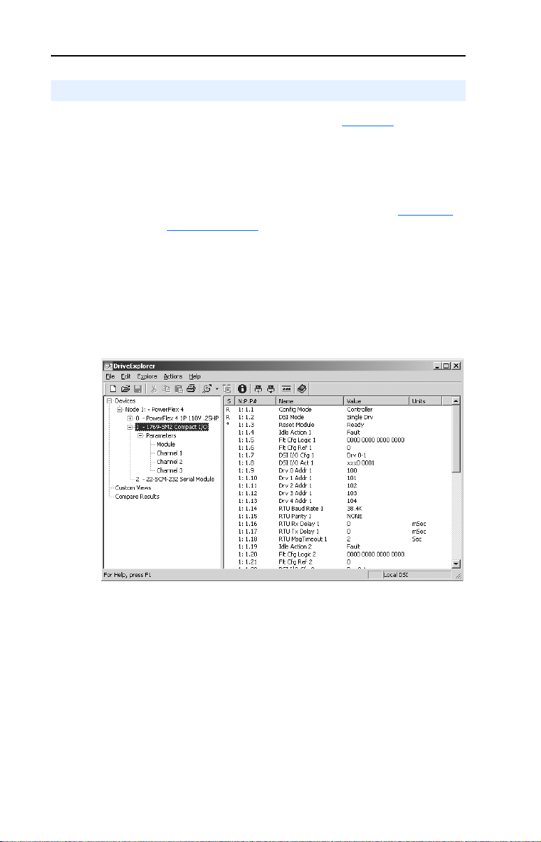
Parameter Mode
When the Configuration Mode Switch (SW1 in Figure 2.1) is in the
PARAM (Parameter) position, the 1769-SM2 uses its internal parameter
settings to configure the module. If any configuration data is downloaded
by the controller, it will be ignored.
Important: When the Parameter mode is used, the configuration data
size in the controller should be set to “0.” See Controller
Mode on page 3-3 for more information.
Host PowerFlex 4-Class drives can use this feature since connected DSI
peripheral devices (optional, external PowerFlex 4-Class HIMs,
DriveExplorer with 22-SCM-232, etc.) can access the 1769-SM2 module
directly. However, the 1769-SM2 module must be set to Single mode for
these DSI peripherals to work with the module.
Figure 3.13 DriveExplorer Window with Mapped 1769-SM2 Compact I/O Module
Page 51
Configuring the Module 3-13
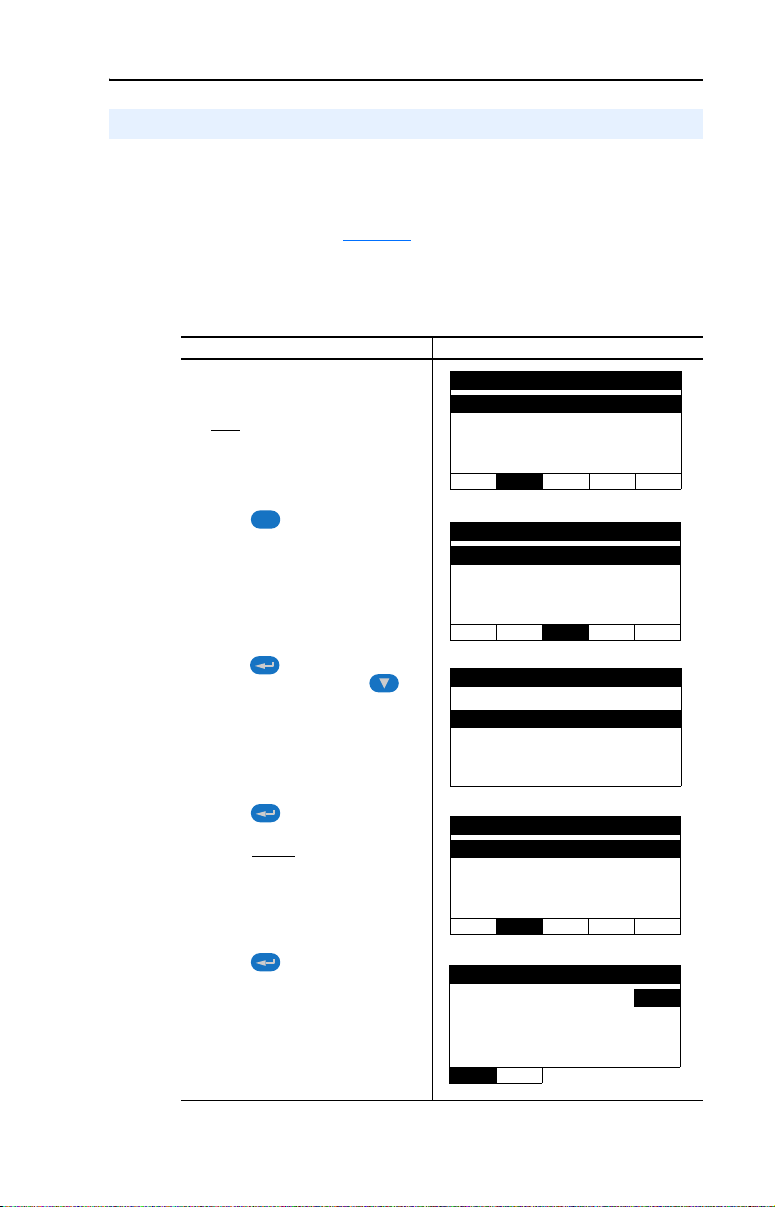
Using the Optional, External PowerFlex 4-Class HIM
When using the 1769-SM2 module in Single mode, the optional,
external PowerFlex 4-Class HIM (Human Interface Module) can be used
to access its parameters. Basic steps to access module parameters using
the HIM are shown in Table 3.E
to the PowerFlex 4-Class HIM Quick Reference (publication
22HIM-QR001).
Table 3.E Accessing Module Parameters Using the HIM (22-HIM-A3 or 22-HIM-C2S)
Step Example Screens
1. Power up the drive. Then plug the
external HIM into the bottom of the
drive. The Parameters menu for the
drive
will be displayed.
. For additional HIM information, refer
Parameters
Groups
Linear List
Changed Params
DIAG PA R A M DSEL MEM SEL
2. Press key once to display the
Sel
Device Select menu.
3. Press (Enter) key to display the
DSI Devices menu. Press
Arrow to scroll to 1769-SM2.
4. Press (Enter) key to select the
1769-SM2. The Parameters menu
for the module
5. Press (Enter) key to access
the parameters. Edit the module
parameters using the same
techniques that you use to edit drive
parameters.
will be displayed.
Device Select
DSI Devices
DIAG PARAM DSEL MEM SEL
DSI Devices
PowerFlex 4 0
1769-SM2
Parameters
Linear List
Changed Params
DIAG PA R A M DSEL MEM SEL
Mode RO
Parameter : #
0 = Controller
VAL UE LIMITS SEL
001
Page 52
3-14 Configuring the Module
Setting the I/O Configuration (Multi-Drive Mode Only)
The I/O configuration sets the number of drives that are connected to
each channel. When the 1769-SM2 module is used in Single mode
(Operating Mode Switch SW2 set to “1X”), only one PowerFlex 4-Class
drive can be connected to each channel and module Parameters 07 -
[DSI I/O Cfg 1], 22 - [DSI I/O Cfg 2], and 37 - [DSI I/O Cfg 3] have no
effect. When the module is used in Multi-Drive mode (Operating Mode
Switch set to “5X”), up to five PowerFlex 4-Class drives can be
connected to each channel. When a channel is selected for Modbus RTU
Master operation, up to 31 devices can be connected.
1. Set the value in Parameters 07 - [DSI I/O Cfg 1], 22 - [DSI I/O Cfg
2], and 37 - [DSI I/O Cfg 3] to respectively configure each module
channel for the number of drives being used in Multi-Drive mode.
Figure 3.14 Example I/O Cfg Screen for CH1 Drive(s) in Multi-Drive Mode
DSI I/O Cfg 1
Parameter : #
Drives 0…4 4
VALU E LIMITS SEL
Each drive (Drive 0, Drive 1, etc.) on the node must be assigned a
node address [see Setting Drive Node Addresses (Multi-Drive Mode
Only) on page 3-16]. For more information on Multi-Drive mode and
RTU Master mode, refer to the Multi-Drive Mode section in the
chapter corresponding to your controller type:
• Chapter
• Chapter 7, CompactLogix Example Ladder Programs
• Chapter 8, ControlLogix w/1769-ADN DeviceNet Example
2. Configure the parameters in each enabled drive to accept the Logic
Command and Reference from the 1769-SM2 module. For example,
set PowerFlex 4/40/400 drive Parameters 36 - [Start Source] and 38 [Speed Reference] to “5” (Comm Port) so that the drive uses the
Reference from the 1769-SM2 module.
6, MicroLogix 1500 Example Ladder Programs
Ladder Program
007
Value Description
0 Drive 0 (Default) ✓✓
1Drives 0…1
2Drives 0…2 ✓
3Drives 0…3 ✓
4Drives 0…4 ✓
5 RTU Master ✓
Mode Switch Position
Single Multi-Drive
✓
Not Applicable
3. Reset the module (see Resetting the Module
on page 3-20).
Page 53

Configuring the Module 3-15
Setting an Idle Action (Single and Multi-Drive Mode)
By default, when the controller is idle, the drive responds by faulting
when using I/O from the 1769-SM2 module. You can respectively
configure a different response to an idle controller using Parameters 04
- [Idle Action 1], 19 - [Idle Action 2], and 34 - [Idle Action 3] for each
channel’s connected drives.
ATTENTION: Risk of injury or equipment damage exists.
Parameters 04 - [Idle Action 1], 19 - [Idle Action 2], and 34 - [Idle
!
Action 3] let you determine the action of each respective channel’s
connected PowerFlex 4-Class drives when the controller is idle. By
default, each parameter faults its respective channel’s drives. You can
set each parameter so that the respective channel’s drives continue to
run. Precautions should be taken to ensure that the settings of these
parameters do not create a hazard of injury or equipment damage.
Changing the Idle Action
Set the values of Parameters 04 - [Idle Action 1], 19 - [Idle Action 2],
and 34 - [Idle Action 3] to the desired responses:
Value Action Description
0 Fault (default) The drive(s) is faulted and stopped. (Default)
1 Stop The drive(s) is stopped, but not faulted.
2 Zero Data The drive(s) is sent 0 for Logic Command and Reference after a
3 Hold Last The drive(s) continues in its present state after a communications
4 Send Flt Cfg The drive(s) is sent the data that you set in the fault configuration
communications disruption. This does not command a stop.
disruption.
parameters. For:
CH1 drives, Parameters 05 - [Flt Cfg Logic 1] and 06 - [Flt Cfg Ref 1]
CH2 drives, Parameters 20 - [Flt Cfg Logic 2] and 21 - [Flt Cfg Ref 2]
CH3 drives, Parameters 35 - [Flt Cfg Logic 3] and 36 - [Flt Cfg Ref 3]
Figure 3.15 Example Idle Action HIM Screen for CH1 Drive(s)
Idle Action 1
Parameter: #
004
Fault 0
VAL UE LIMITS SEL
Changes to these parameters take effect immediately. A reset is not
required.
Important: In Multi-Drive mode, the same fault action is used by all of
that channel’s connected drives (Drive 0…Drive 4).
Page 54

3-16 Configuring the Module
ATTENTION: Idle Action is NOT available for RTU Master
operation in Multi-Drive mode. The connected RTU Slave devices will
!
take their respective internal fault actions in response to receiving no
communications from the 1769-SM2 module.
Setting the Fault Configuration Parameters
If you set Parameter 04 - [Idle Action 1], 19 - [Idle Action 2], or 34 [Idle Action 3] to “Send Flt Cfg,” the values in the following 1769-SM2
module parameters are sent to the drive after an idle action occurs. You
must set these parameters to values required by your application.
Parameter No.
Name DescriptionCH1 CH2 CH3
05 20 35 Flt Cfg Logic A 16-bit value sent to the drive for Logic Command. Refer to
06 21 36 Flt Cfg Ref A 16-bit value sent to the drive as a Reference. Format is:
Changes to these parameters take effect immediately. A reset is not required.
Appendix
D for a description of the Logic Command bits.
xxx.x Hz. for PowerFlex 4/4M/40/40P drives
xxx.xx Hz. for PowerFlex 400 drives
Setting Drive Node Addresses (Multi-Drive Mode Only)
When using the 1769-SM2 module in Multi-Drive mode, a unique node
address must be set for each drive. Use the following parameters to set
the drive node addresses:
For CH1 Drives Parameters 09 - [Drv 0 Addr 1] through 13 - [Drv 4 Addr 1]
For CH2 Drives Parameters 24 - [Drv 0 Addr 2] through 28 - [Drv 4 Addr 2]
For CH3 Drives Parameters 39 - [Drv 0 Addr 3] through 43 - [Drv 4 Addr 3]
Important: The setting for each of these parameters must match the
drive Parameter 104 - [Comm Node Addr] value for each
respective drive. Each drive node address must be unique
(no duplicate node addresses).
Figure 3.16 Example Node Address HIM Screen for CH1 Drive 0
009
Default: 100
Minimum: 1
Maximum: 247
Drv 0 Addr 1
Parameter : #
100
VAL UE LIMITS SEL
Page 55
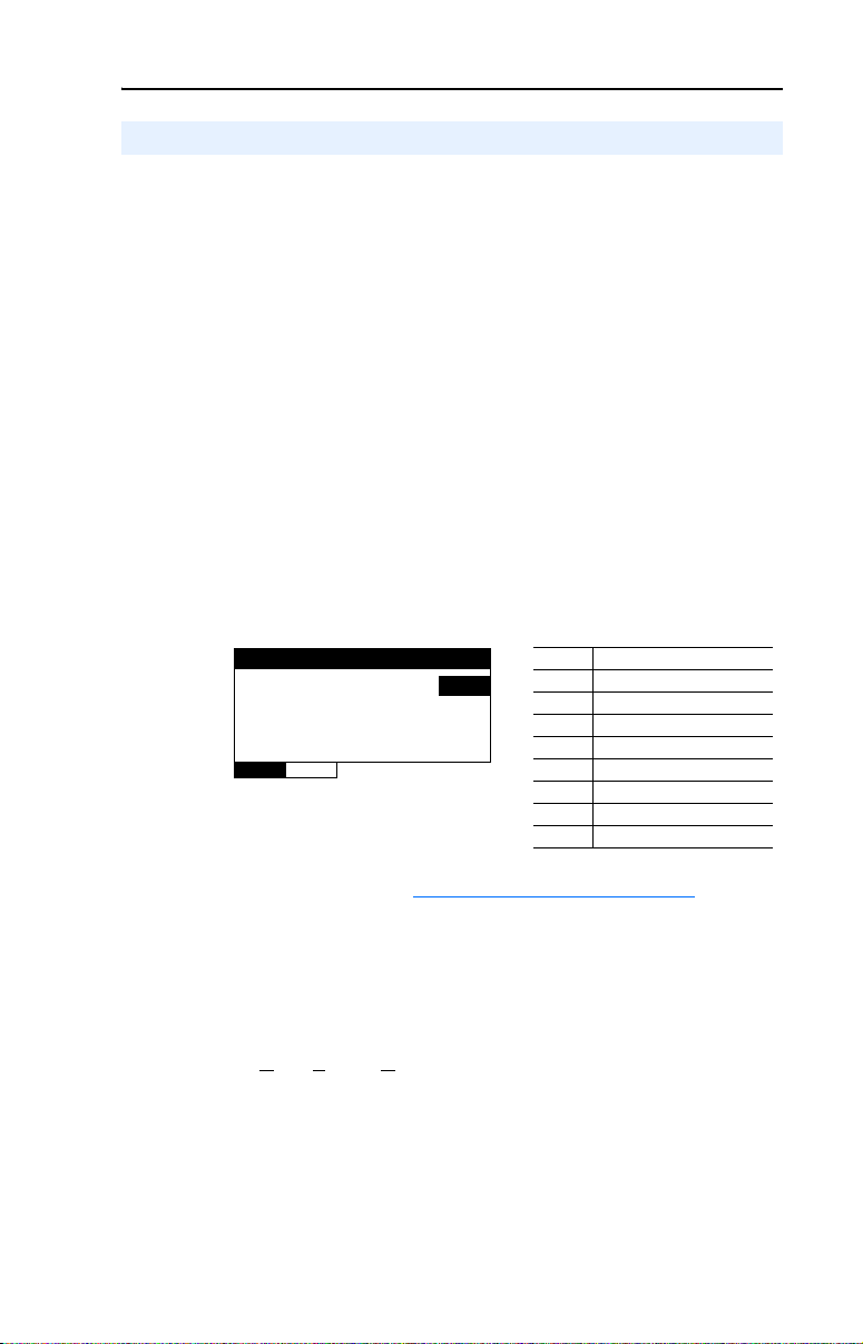
Configuring the Module 3-17
Configuring the Modbus RTU Master Parameters
In Multi-Drive mode, any module channel can be configured for RTU
Master operation by setting Parameter 07 - [DSI I/O Cfg 1], 22 - [DSI
I/O Cfg 2] or 37 - [DSI I/O Cfg 3] to “5” (RTU Master). When doing
this, additional Modbus RTU Master parameters must be set to complete
that channel’s configuration.
Setting the RTU Baud Rate
By default, each channel set for RTU Master operation uses a 38.4K
baud rate. The values of Parameters 14 - [RTU Baud Rate 1], 29 -
[RTU Baud Rate 2], and 44 - [RTU Baud Rate 3] set the specific baud
rate used by the respective channel to communicate.
1. Set the values of Parameters 14 - [RTU Baud Rate 1], 29 - [RTU
Baud Rate 2], and 44 - [RTU Baud Rate 3] to the specific baud rate
at which that channel communicates.
Figure 3.17 Example RTU Baud Rate HIM Screen for CH1 Drives
RTU Baud Rate 1
Parameter : #
0
VAL UE LIMITS SEL
014
Value Baud Rate
0 38.4K bits/sec (default)
1 19200 bits/sec
2 9600 bits/sec
3 4800 bits/sec
4 2400 bits/sec
5 1200 bits/sec
6 600 bits/sec
7 300 bits/sec
2. Reset the module (see Resetting the Module on page 3-20).
Selecting the RTU Format
By default, each channel set for RTU Master operation uses an RTU
format of 8-N-1. The RTU format consists of data bits (8 data bits only),
parity (N
1. Set the values of Parameters 15 - [RTU Format 1], 30- [RTU
one, Even or Odd), and stop bits (1 or 2).
Format 2], and 45 - [RTU Format 3] to match the communication
format required for the respective channel.
Page 56
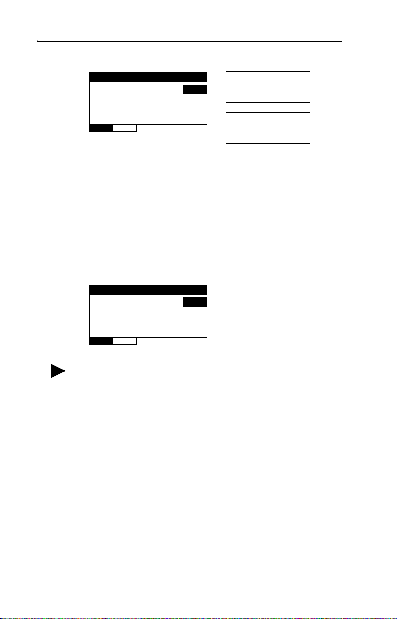
3-18 Configuring the Module
Figure 3.18 Example RTU Format HIM Screen for CH1 Drives
RTU Format 1
Parameter : #
VAL UE LIMITS SEL
2. Reset the module (see Resetting the Module on page 3-20).
Setting the RTU Rx Delay Time
1. Set the values of Parameters 16 - [RTU Rx Delay 1], 31- [RTU Rx
Delay 2], and 46 - [RTU Rx Delay 3] to establish the inter-character
delay time that detects the end of a receive packet for the respective
channel.
Figure 3.19 Example RTU Rx Delay HIM Screen for CH1 Drives
RTU Rx Delay 1
Parameter : #
Value Forma t
015
0
016
0
0 8-N-1 (default)
1 8-E-1
2 8-O-1
3 8-N-2
4 8-E-2
5 8-O-2
Default: 0 milliseconds
Minimum: 0 milliseconds
Maximum: 500 milliseconds
VAL UE LIMITS SEL
TIP: If the Modbus RTU slave is a PowerFlex 4-Class drive, set the
value of [RTU Rx Delay x] to 2 milliseconds when the value of
[RTU Baud Rate x] is 19200.
2. Reset the module (see Resetting the Module on page 3-20).
Setting the RTU Tx Delay Time
1. Set the values of Parameters 17 - [RTU Tx Delay 1], 32- [RTU Tx
Delay 2], and 47 - [RTU Tx Delay 3] to establish the inter-frame
delay time that delays the sending of a transmit packet for the
respective channel.
Page 57

Configuring the Module 3-19
Figure 3.20 Example RTU Tx Delay HIM Screen for CH1 Drives
RTU Tx Delay 1
Parameter : #
0
VAL UE LIMITS SEL
TIP: If the Modbus RTU slave is a PowerFlex 4-Class drive, set the
value of [RTU Tx Delay x] to 8 milliseconds when the value of
[RTU Baud Rate x] is 19200.
2. Reset the module (see Resetting the Module on page 3-20).
Setting the RTU Message Timeout
1. Set the values of Parameters 18 - [RTU MsgTimeout 1], 33- [RTU
MsgTimeout 2], and 48 - [RTU MsgTimeout 3] to establish the
amount of time that the module will wait for a response from the
respective channel’s drives.
Figure 3.21 Example RTU MsgTimeout HIM Screen for CH1 Drives
017
Default: 0 milliseconds
Minimum: 0 milliseconds
Maximum: 500 milliseconds
RTU MsgTimeout 1
Parameter : #
2
VAL UE LIMITS SEL
Important: The RTU Message Timeout value must be considered
when determining the timeout values in the slave nodes.
2. Reset the module (see Resetting the Module
TIP: When configured for RTU Master operation, the RTU Slave
addresses do not get assigned with parameter values. The Slave
address is contained in the message data as described in Chapter
For example, if five RTU messages are being sent to a
slave node and the slave is powered down, the overall
network cycle time can increase by as much as 10
seconds (5 messages x 2 seconds timeout for each slave
node).
018
Default: 2 seconds
Minimum: 0 seconds
Maximum: 60 seconds
on page 3-20).
5.
Page 58

3-20 Configuring the Module
Resetting the Module
Changes to switch settings and some module parameters require that you
reset the 1769-SM2 module before the new settings take effect. You can
reset the module by cycling power to the module or by using Parameter
03 - [Reset Module].
ATTENTION: Risk of injury or equipment damage exists. If the
module is transmitting control I/O to the drive, the drive may fault when
!
you reset the module. Determine how your drive will respond before
resetting a connected module.
Set Parameter 03 - [Reset Module] to “1” (Reset Module):
Figure 3.22 Example Reset Module HIM Screen
Reset Module
Parameter : #
Ready 0
003
VAL UE LIMITS SEL
When you enter “1” (Reset Module), the module will be immediately
reset. When you enter “2” (Set Defaults), the module will set all module
parameters to their factory-default settings. After performing a Set
Defaults, enter “1” (Reset Module) so that the new values take effect.
The value of this parameter will be restored to “0” (Ready) after the
module is reset.
Value Description
0 Ready (Default)
1 Reset Module
2 Set Defaults
Page 59

Configuring the Module 3-21
Viewing the Module Status Using Parameters
The following parameters provide information about the status of the
1769-SM2 module. You can view these parameters at any time.
Parameter Description
01 - [Config Mode] The module configuration mode (Controller or Parameters).
02 - [DSI Mode] The module operating mode (Single or Multi-Drive).
08 - [DSI I/O Act 1] The CH1 drives that are active in Multi-Drive mode.
Bit
Definition
Default x xx00001
Bit 76543210
Not Used
Not Used
Not Used
Drive 4
Drive 3
Drive 2
Drive 1
Drive 0
0 = Drive Active
1 = Drive Inactive
09 - [Drv 0 Addr 1]
10 - [Drv 1 Addr 1]
11 - [Drv 2 Addr 1]
12 - [Drv 3 Addr 1]
13 - [Drv 4 Addr 1]
23 - [DSI I/O Act 2] The CH2 drives that are active in Multi-Drive mode.
24 - [Drv 0 Addr 2]
25 - [Drv 1 Addr 2]
26 - [Drv 2 Addr 2]
27 - [Drv 3 Addr 2]
28 - [Drv 4 Addr 2]
38 [DSI I/O Act 3] The CH3 drives that are active in Multi-Drive mode.
The node addresses of the daisy-chained CH1 drives (only when
in Multi-Drive mode).
Important: The setting for each of these parameters must match
the drive Parameter 104 - [Comm Node Addr] value for each
respective drive. Each drive node address must be unique (no
duplicate node addresses).
Bit
Definition
Default x xx00001
Bit 76543210
The node addresses of the daisy-chained CH2 drives (only when
module is operated in Multi-Drive mode).
Important: The setting for each of these parameters must match
the drive Parameter 104 - [Comm Node Addr] value for each
respective drive. Each drive node address must be unique (no
duplicate node addresses).
Not Used
Not Used
Not Used
Drive 4
Drive 3
Drive 2
Drive 1
Drive 0
0 = Drive Active
1 = Drive Inactive
Bit
39 - [Drv 0 Addr 3]
40 - [Drv 1 Addr 3]
41 - [Drv 2 Addr 3]
42 - [Drv 3 Addr 3]
43 - [Drv 4 Addr 3]
Definition
Default x xx00001
Bit 76543210
The node addresses of the daisy-chained CH3 drives (only when
module is operated in Multi-Drive mode).
Important: The setting for each of these parameters must match
the drive Parameter 104 - [Comm Node Addr] value for each
respective drive. Each drive node address must be unique (no
duplicate node addresses).
Not Used
Not Used
Not Used
Drive 4
Drive 3
Drive 2
Drive 1
Drive 0
0 = Drive Active
1 = Drive Inactive
Page 60

3-22 Configuring the Module
Flash Updating the Module
The adapter can be flash updated over the network (via EtherNet/IP
using DriveExplorer Full only) or serially through a direct connection
from a computer to the drive using a 1203-USB converter or
22-SCM-232 serial converter module (firmware v2.005 or higher).
Not all flash methods (DriveExplorer Lite/Full, ControlFLASH or
HyperTerminal) can be used successfully in all cases. Depending on the
controller and the operating mode of the 1769-SM2 module, these flash
methods can be used:
Controller
MicroLogix 1500 Single DriveExplorer Lite/Full, ControlFLASH or
CompactLogix Single • DriveExplorer Lite/Full, ControlFLASH or
Important: In ALL cases, the controller must be set to Program
To obtain a flash update for this adapter, go to http://www.ab.com/
support/abdrives/webupdate. This site contains all firmware update files
and associated Release Notes that describe firmware update
enhancements/anomalies, how to determine the existing firmware
version, and how to flash update using DriveExplorer Lite/Full,
ControlFLASH or HyperTerminal.
1769-SM2
Operating Mode Flash Methods to Use
HyperTerminal via a 1203-USB or 22-SCM-232
converter
Multi-Drive Must first change the 1769-SM2 operating mode
Multi-Drive ControlFLASH via the CompactLogix controller
mode—not the Run mode—to successfully flash the
1769-SM2 module.
from Multi-Drive to Single before flashing. Then
flash using any of the methods listed in the row
above.
HyperTerminal via a 1203-USB or
22-SCM-232 converter
• ControlFLASH via the CompactLogix
controller backplane
backplane
Page 61

Chapter 4
Understanding the I/O Image
This chapter provides information and examples of the 1769-SM2
module I/O image, including Module Control/Status, Logic Command/
Status, and Reference/Feedback.
Topic Page
Module Control Word
Module Status Word 4-3
Using Logic Command/Status 4-4
Using Reference/Feedback 4-4
The I/O image for the 1769-SM2 module varies based on its selected
operating mode (Single or Multi-Drive), and the settings for Parameters
07 - [DSI I/O Cfg 1], 22 - [DSI I/O Cfg 2], and 37 - [DSI I/O Cfg 3].
Table 4.A 1769-SM2 Module I/O Image Table for Single Mode
Output Image Input Image
Module Control Word Module Status Word 0
Logic Command Logic Status 1 3 5
Reference Feedback 2 4 6
Table 4.B 1769-SM2 Module I/O Image Table for Multi-Drive Mode
Output Image Input Image
Module Control Word Module Status Word 0
Logic Command Logic Status 1 11 21
Drive 0
Reference Feedback 2 12 22
Logic Command Logic Status 3 13 23
Drive 1
Reference Feedback 4 14 24
Logic Command Logic Status 5 15 25
Drive 2
Reference Feedback 6 16 26
Logic Command Logic Status 7 17 27
Drive 3
Reference Feedback 8 18 28
Logic Command Logic Status 9 19 29
Drive 4
Reference Feedback 10 20 30
4-2
Wor d
CH1 CH2 CH3
Word
CH1 CH2 CH3
Note that the I/O words for each channel are contiguous, keeping the
required I/O space to a minimum. For example, to connect one
PowerFlex 40 drive in Single mode and perform control (Logic
Command/Status and Reference/Feedback), only 3 words of I/O are
Page 62

4-2 Understanding the I/O Image
needed. Likewise, five PowerFlex drives on CH1 in Multi-Drive mode
using control would require 11 words of I/O.
TIP: To minimize the number of I/O words needed, connect the drive(s)
starting with CH1, followed by CH2, and then CH3.
Table 4.C 1769-SM2 Module I/O Image Examples
Operating
Mode
Single “0” (Drive 0) “0” (Drive 0) “0” (Drive 0) 7 3 (1/channel)
Multi-Drive
(1)
If CH2 and CH3 would not be used (only 5 drives connected to CH1), the I/O size in the RSLogix 500/5000 module
configuration window could be set to “11” instead of “23” to save I/O space.
(2)
If CH3 would not be used (only CH1 and CH2 have 5 drives each), the I/O size in the RSLogix 500/5000 module
configuration window could be set to “21” instead of “23” to save I/O space.
CH1
Parameter 07 [DSI I/O Cfg 1]
“0” (Drive 0) “0” (Drive 0) “0” (Drive 0) 23 3 (1/channel)
“4” (Drive 0…4) “0” (Drive 0) “0” (Drive 0) 23
“4” (Drive 0…4) “4” (Drive 0…4) “0” (Drive 0) 23
“4” (Drive 0…4) “4” (Drive 0…4) “4” (Drive 0…4) 31 15 (5/each CH)
CH2
Parameter 22 [DSI I/O Cfg 2]
CH3
Parameter 37 [DSI I/O Cfg 3]
Maximum
I/O Words
Used
(1)
(2)
Maximum Drives
Connected
7 (5/CH1, 1/CH2,
and 1/CH3)
11 (5/CH1, 5/CH2,
and 1/CH3)
Module Control Word
The Module Control Word (output word 0) is used for all channels, where:
Bit # Name Description
0 Channel 1 Enable “0” = Disables sending output data (Logic Command/
1 Channel 2 Enable
2 Channel 3 Enable
3…15 Not used Reserved for future use.
The Module Control Word is a “master” enable/disable switch for
communications on each channel when using the module in Single or
Multi-Drive mode (only DSI operation). The actual output/input data
being sent/received is determined by Parameter 07 - [DSI I/O Cfg 1],
Parameter 22 - [DSI I/O Cfg 2], and Parameter 37 - [DSI I/O Cfg 3].
Important: If the Channel “x” Enable bit is transitioned from ON (1) to
OFF (0), the connected PowerFlex 4-Class drives will fault.
The Channel “x” Enable bits are not used when the module is configured
for Modbus RTU Master operation in Multi-Drive mode.
Reference) to the respective channel’s drive(s). All
input (Logic Status/Feedback) data is zeroed (“0”) to
indicate that the data is no longer being updated.
“1” = Enables sending output data (Logic Command/
Reference) to the respective channel’s drive(s). All
respective input data will also be updated.
Page 63

Understanding the I/O Image 4-3
Module Status Word
The Module Status Word (input word 0) is used for all channels, where:
Bit # Bit Name Description
0 CH1 Logic Status 0 Valid “0” = Logic Status/Feedback data for CH1 Drive 0 is not valid
1 CH1 Logic Status 1 Valid “0” = Logic Status/Feedback data for CH1 Drive 1 is not valid
2 CH1 Logic Status 2 Valid “0” = Logic Status/Feedback data for CH1 Drive 2 is not valid
3 CH1 Logic Status 3 Valid “0” = Logic Status/Feedback data for CH1 Drive 3 is not valid
4 CH1 Logic Status 4 Valid “0” = Logic Status/Feedback data for CH1 Drive 4 is not valid
5 CH2 Logic Status 0 Valid “0” = Logic Status/Feedback data for CH2 Drive 0 is not valid
6 CH2 Logic Status 1 Valid “0” = Logic Status/Feedback data for CH2 Drive 1 is not valid
7 CH2 Logic Status 2 Valid “0” = Logic Status/Feedback data for CH2 Drive 2 is not valid
8 CH2 Logic Status 3 Valid “0” = Logic Status/Feedback data for CH2 Drive 3 is not valid
9 CH2 Logic Status 4 Valid “0” = Logic Status/Feedback data for CH2 Drive 4 is not valid
10 CH3 Logic Status 0 Valid “0” = Logic Status/Feedback data for CH3 Drive 0 is not valid
11 CH3 Logic Status 1 Valid “0” = Logic Status/Feedback data for CH3 Drive 1 is not valid
12 CH3 Logic Status 2 Valid “0” = Logic Status/Feedback data for CH3 Drive 2 is not valid
13 CH3 Logic Status 3 Valid “0” = Logic Status/Feedback data for CH3 Drive 3 is not valid
14 CH3 Logic Status 4 Valid “0” = Logic Status/Feedback data for CH3 Drive 4 is not valid
15 Config Valid “1” = The module has a valid configuration
“1” = Logic Status/Feedback data for CH1 Drive 0 is valid
“1” = Logic Status/Feedback data for CH1 Drive 1 is valid
“1” = Logic Status/Feedback data for CH1 Drive 2 is valid
“1” = Logic Status/Feedback data for CH1 Drive 3 is valid
“1” = Logic Status/Feedback data for CH1 Drive 4 is valid
“1” = Logic Status/Feedback data for CH2 Drive 0 is valid
“1” = Logic Status/Feedback data for CH2 Drive 1 is valid
“1” = Logic Status/Feedback data for CH2 Drive 2 is valid
“1” = Logic Status/Feedback data for CH2 Drive 3 is valid
“1” = Logic Status/Feedback data for CH2 Drive 4 is valid
“1” = Logic Status/Feedback data for CH3 Drive 0 is valid
“1” = Logic Status/Feedback data for CH3 Drive 1 is valid
“1” = Logic Status/Feedback data for CH3 Drive 2 is valid
“1” = Logic Status/Feedback data for CH3 Drive 3 is valid
“1” = Logic Status/Feedback data for CH3 Drive 4 is valid
The data valid bits (0…14) can be used in the ladder program to
determine if the received data is valid and can be used. Bit 15 provides
diagnostic feedback on the status of the 1769-SM2 module
configuration.
When the module is configured for RTU Master operation in
Multi-Drive mode, bits 0…14 are not used and will be “0.”
Page 64
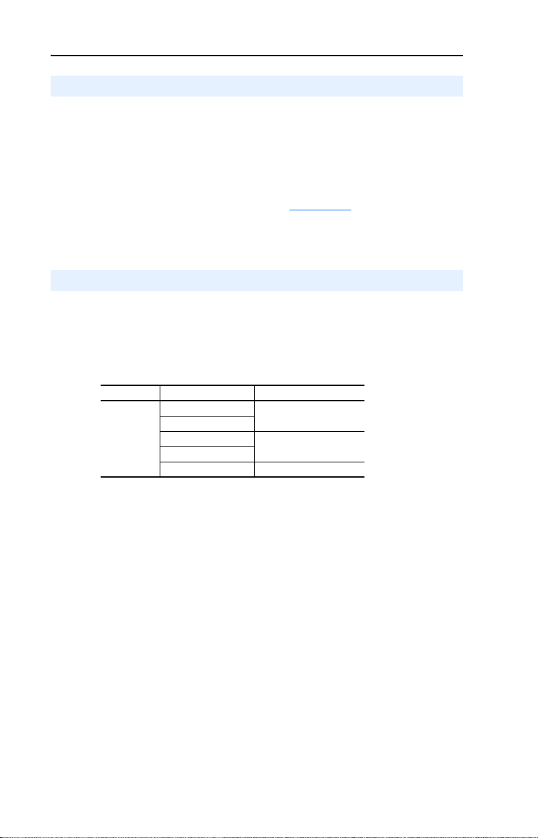
4-4 Understanding the I/O Image
Using Logic Command/Status
The Logic Command is a 16-bit word of control data produced by the
controller and consumed by the 1769-SM2 module. The Logic Status is a
16-bit word of status data produced by the 1769-SM2 module and
consumed by the controller.
This manual contains the bit definitions for compatible products
available at the time of publication in Appendix
refer to their documentation.
Using Reference/Feedback
The Reference (16 bits) is produced by the controller and consumed by
the 1769-SM2 module. The Feedback (16 bits) is produced by the
1769-SM2 module and consumed by the controller.
Valid Reference/Feedback values for PowerFlex 4-Class drives are:
Size Drive Valid Values
PowerFlex 4
PowerFlex 4 M
16-bit
(1)
The Reference/Feedback for a PowerFlex 4-Class drive is set in Hz and
not in engineering units like PowerFlex 7-Class drives. For example,
“300” equates to 30.0 Hz (the decimal point is always implied) for all
PowerFlex 4-Class drives—except PowerFlex 400 for which “3000”
equates to 30.00 Hz. In all cases, a minus value equates to reverse
motor direction, and a plus value equates to forward motor direction.
PowerFlex 4 0
PowerFlex 40P
PowerFlex 400 -320.00…320.00 Hz
D. For other products,
(1)
-240.0…240.0 Hz
-400.0…400.0 Hz
Page 65

Chapter 5
Understanding Explicit Messaging
This chapter provides information about explicit messaging.
Topic Page
Formatting Explicit Messages
Modbus RTU Master Operation Messages 5-9
Explicit messaging is used to read/write data that is not part of the
module’s I/O Image (Chapter
• Reading/writing drive parameters.
• Operating as a Modbus RTU Master and initiating Request/Response
messages to Modbus RTU Slave devices, such as PowerFlex 7-Class
drives with 20-COMM-H adapters.
The following table shows various products that can be used with the
1769-SM2 module and whether they support explicit messaging:
4), such as:
5-2
Products
MicroLogix 1500 LRP Series A and B, and
LSP processors
MicroLogix 1500 LRP Series C (or newer) and
RSLogix 500 v6.30 (or higher)
Important: This LRP processor supports messaging
only for the first two I/O modules capable of messaging.
RSLogix 500 versions prior to v6.30 ✔
Enhanced CompactLogix processors such as the -L31,
-L32E, and -L35E
CompactLogix -L20 and -L30 processors ✔
1769-ADN DeviceNet adapter (see documentation for
possible future explicit messaging support)
Contact your local Rockwell Automation, Inc. representative for
inquiries about the explicit message capabilities of products not
specified above.
ATTENTION: Hazard of equipment damage exists. If Explicit
Messages are programmed to write parameter data to Non-Volatile
!
Storage (NVS) frequently, the NVS will quickly exceed its life cycle
and cause the drive to malfunction. Do not create a program that
frequently uses Explicit Messages to write parameter data to NVS.
Supports Explicit Messaging
Yes N o
✔
✔
✔
✔
Page 66
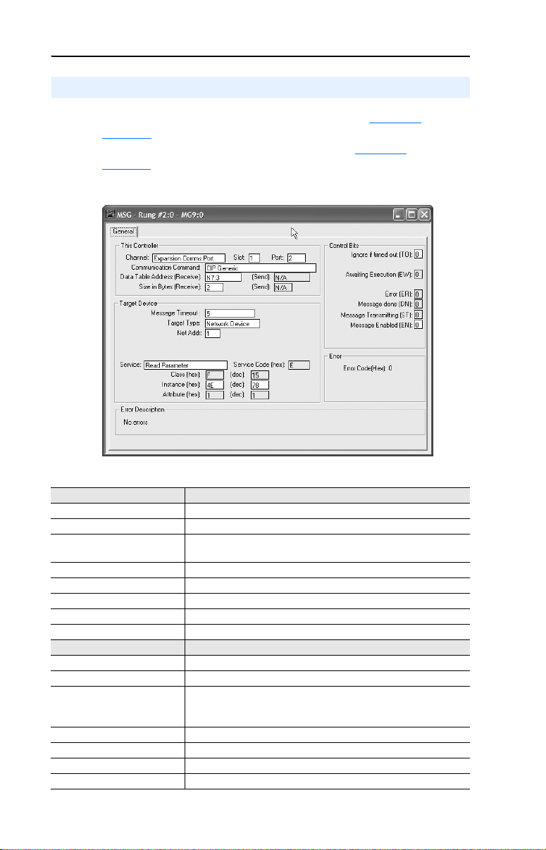
5-2 Understanding Explicit Messaging
Formatting Explicit Messages
For RSLogix 500, format each message as shown in Figure 5.1 and see
Table 5.A
RSLogix 5000, format each message as shown in Figure 5.2 and see
Table 5.B.
Figure 5.1 RSLogix 500 Explicit Message Setup Screen
for a description of the data required in each field. For
Table 5.A RSLogix 500 Explicit Message Configuration Data
This Controller Section Description
Channel Always use “Expansion Comms Port.”
Slot The chassis slot occupied by the 1769-SM2 module.
Port Always set to “2.” Note: This field was not configurable in earlier
Communication Command Always use “CIP Generic.”
Data Table Address (Receive) The file and element where response service data (if any) is stored.
Size in Bytes (Receive) Number of bytes of response service data (if any).
Data Table Address (Send) The file and element where request service data (if any) is stored.
Size in Bytes (Send) Number of bytes of request service data (if any).
Target Device Section Description
Message Timeout The timeout delay in seconds.
Target Type Always use “Network Device.”
Net Addr The number of the channel (1…3) on the 1769-SM2 module where
Service (Text or hex) Code for the requested service.
Class (hex or dec) The Class ID.
Instance (hex or dec) Instance number is the same as the parameter number.
Attribute (hex or dec) Attribute number.
versions of RSLogix 500.
the message will be sent. Note: This field was called “Channel” in
earlier versions of RSLogix 500.
Page 67
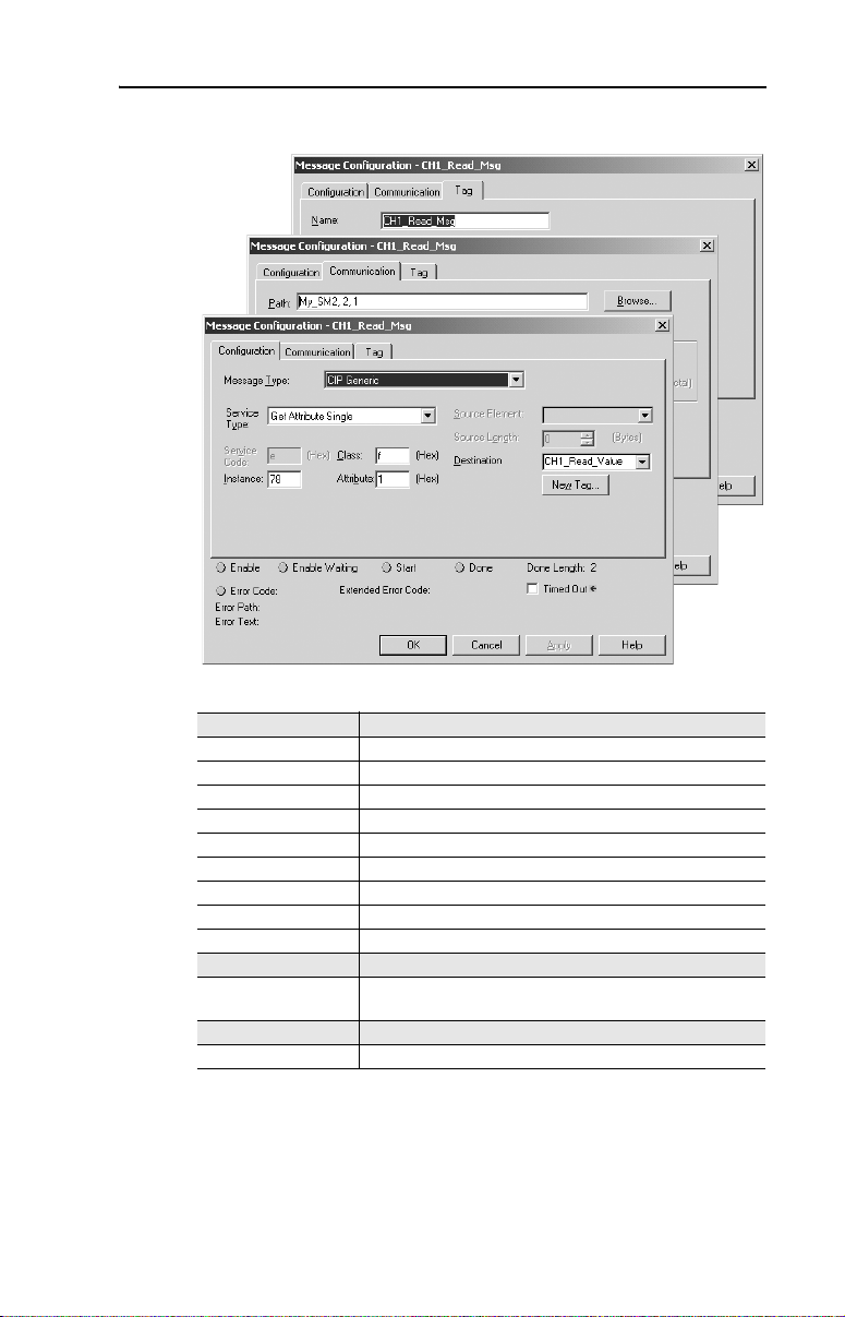
Understanding Explicit Messaging 5-3
Figure 5.2 RSLogix 5000 Explicit Message Setup Screen
Table 5.B RSLogix 5000 Explicit Message Configuration Data
Configuration Tab Description
Message Type Always use “CIP Generic.”
Service Type The service is used to read/write a parameter value.
Service Code Code for the requested service.
Class Class ID for the DSI Parameter Object.
Instance Instance number in the Class.
Attribute Attribute number of the Instance.
Source Element Source of the request service data.
Source Length Length of the request service data.
Destination Location where the response service data (if any) is stored.
Communication Tab Description
Path Format is <Name of Module>,2,n — where “n” equals the
Tag Tab Description
Name The name for the message instruction.
channel number (1…3) on the 1769-SM2.
Page 68

5-4 Understanding Explicit Messaging
Table 5.C shows the instance numbers to be used for message
configuration:
Table 5.C Instance Numbers for Message Configuration
Instances (Dec.) Single Mode Multi-Drive Mode
0…16383 Instances 0…1023 in drive/module
16384…17407 Instances 0…1023 in module Instances 0…1023 in module
17408…18431 Instances 0…1023 in drive Instances 0…1023 in Drive 0
18432…19455 Not supported Instances 0…1023 in Drive 1
19456…20479 Not supported Instances 0…1023 in Drive 2
20480…21503 Not supported Instances 0…1023 in Drive 3
21504…22527 Not supported Instances 0…1023 in Drive 4
(1)
The module parameters are appended to the drive parameters for this range of instances.
Instance “1” typically equates to parameter 1. For example, when using
the 1769-SM2 module in Single mode, instance “17409” is for
parameter 1 in the drive.
NOTE: Instance Attribute 1 is used to access the parameter value. For
additional information, refer to the CIP Parameter Object
(1)
Instances 0…1023 in module
on page C-4.
Page 69
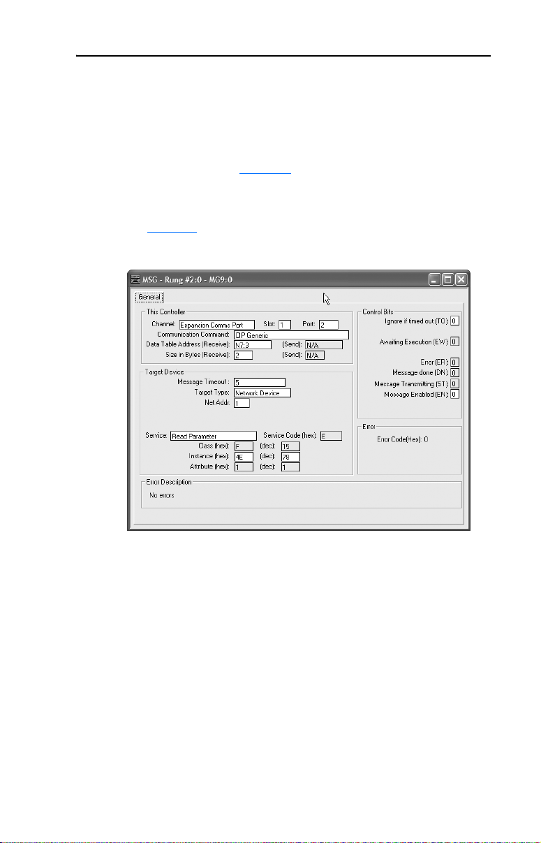
Understanding Explicit Messaging 5-5
RSLogix 500 Parameter Read/Write Examples
In this example, a read and a write of PowerFlex 40 drive Parameter 78
- [Jog Frequency] is being done.
The RSLogix 500 Message Configuration screen example to read a
parameter is shown in Figure 5.3
module occupies slot 1 and is operated in Single mode, and that the drive
is connected to CH1.
. It is assumed that the 1769-SM2
See Table 5.A
Figure 5.3 RSLogix 500 Example Message Setup Screen to Read a Parameter
for descriptions of the message configuration data.
The response data for the message is stored at Data Table Address N7:3.
The Size in Bytes of the response data is 2 bytes because the data size for
PowerFlex 40 drive Parameter 78 - [Jog Frequency] is 2 bytes (1
word). No Data Table Address is specified for the request data, since the
Read Parameter service has no request data.
Page 70
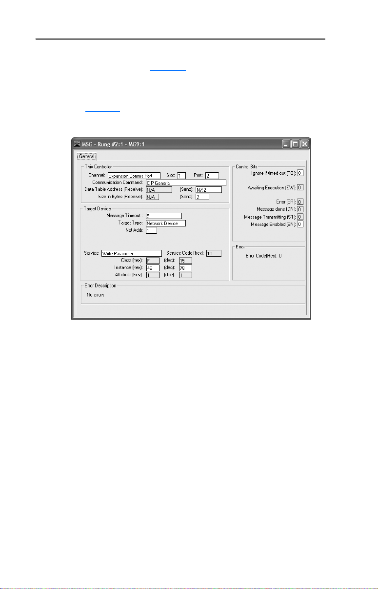
5-6 Understanding Explicit Messaging
The RSLogix 500 Message Configuration example screen to write to a
parameter is shown in Figure 5.4. It is assumed that the 1769-SM2
module occupies slot 1 and is operated in Single mode, and that the drive
is connected to CH1.
See Table 5.A
Figure 5.4 RSLogix 500 Example Message Setup Screen to Write to a Parameter
for descriptions of the message configuration data.
The request data for the message is stored at Data Table Address N7:2.
The Size in Bytes of the request data is 2 bytes because the data size for
PowerFlex 40 drive Parameter 78 - [Jog Frequency] is 2 bytes (1
word). No Data Table Address is specified for the response data, since
the Write Parameter service has no response data.
Page 71

Understanding Explicit Messaging 5-7
RSLogix 5000 Parameter Read/Write Examples
In this example, a read and a write of PowerFlex 40 drive Parameter 78
- [Jog Frequency] is being done.
The RSLogix 5000 Message Configuration example screen to read a
parameter is shown in Figure 5.5
module occupies slot 1 and is operated in Single mode, and that the drive
is connected to CH1.
. It is assumed that the 1769-SM2
See Table 5.B
Figure 5.5 RSLogix 5000 Example Message Setup Screen to Read a Parameter
for descriptions of the message configuration data.
The response data for the message is stored in CH1_Read_Value. The
“Get Attribute Single” Service Type (Service Code “e”) is used to read a
single parameter. Class “f” refers to the CIP Parameter Object on
page C-4 and Instance “78” is drive Parameter 78 - [Jog Frequency].
Instance Attribute “1” is the parameter value.
Page 72
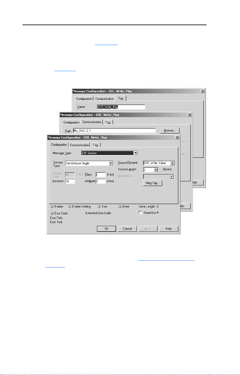
5-8 Understanding Explicit Messaging
The RSLogix 5000 Message Configuration example screen to write to a
parameter is shown in Figure 5.6. It is assumed that the 1769-SM2
module occupies slot 1 and is operated in Single mode, and that the drive
is connected to CH1.
See Table 5.B
Figure 5.6 RSLogix 5000 Example Message Setup Screen to Write to a Parameter
for descriptions of the message configuration data.
The request data for the message is stored in CH1_Write_Value. The
“Set Attribute Single” Service Type (Service Code “10”) is used to write
a single parameter. Class “f” refers to the CIP Parameter Object
page C-4 and Instance “78” is drive Parameter 78 - [Jog Frequency].
Instance Attribute “1” is the parameter value.
on
Page 73

Understanding Explicit Messaging 5-9
Modbus RTU Master Operation Messages
In Multi-Drive mode, any channel can be configured for Modbus RTU
Master operation to communicate with a variety of Rockwell
Automation or 3rd Party RTU Slave devices, such as PowerFlex 7-Class
drives with 20-COMM-H adapters. In the Multi-Drive ladder examples
provided in this manual, CH3 is used to communicate with a PowerFlex
70 drive.
The following Modbus Function Codes are supported:
Function
Code
01 Read Coils 512 05 Write Single Coil n/a
02 Read Discrete Inputs 512 06 Write Single Register n/a
03 Read Holding Registers 32 15 Write Multiple Coils 512
04 Read Input Registers 32 16 Write Multiple Registers 512
Name Maximum
The format of the Modbus command message data is:
Word Name Description
1 RTU Slave Address The node address of the Modbus RTU Slave.
2 Function Code The Modbus Function Code to perform.
3 Starting Address The starting coil/register address in the Slave device.
4 Number of bits/words The number of coils/registers to read/write.
5+ Data Words Only used for write messages and contains the data
The format of the Modbus response message data is:
Word Name Description
1+ Data Words Only used for read messages and contains the data
The format of the message instruction is different for Modbus RTU
Master operation messaging. For RSLogix 500, format each message as
shown in Figure 5.7
required in each field. For RSLogix 5000, format each message as shown
in Figure 5.8
Bits/Word
and see Table 5.D for a description of the data
and see Table 5.E.
Function
Code
to be written.
that was read.
Name Maximum
Bits/Word
Page 74

5-10 Understanding Explicit Messaging
Figure 5.7 RSLogix 500 Modbus RTU Master Message Setup Screen
Table 5.D RSLogix 500 Modbus RTU Master Message Configuration Data
This Controller Section Description
Channel Always use “Expansion Comms Port.”
Slot The chassis slot occupied by the 1769-SM2 module.
Port Always set to “2.” Note: This field was not configurable in earlier
Communication Command Always use “CIP Generic.”
Send (Data Table Address) Starting data table address of the Modbus command data.
Size in Bytes (Receive) Number of bytes of receive data. It is set to “0” for a Modbus write
Send (Size in Bytes) Number of bytes of command data.
Target Device Section Description
Message Timeout Timeout delay in seconds. This value must be greater than the
Target Type Always use “Network Device.”
Net Addr The number of the channel (1…3) on the 1769-SM2 module where
Service Always use “Custom.”
Service Code (hex) Always use “4b.” This is the Execute Modbus service.
Class (hex) Always use “33F.” This is the Class number for the Modbus RTU
Instance (hex or dec) Not used. Leave at “0.”
Attribute (hex or dec) Not used. Leave at “0.”
versions of RSLogix 500.
message, and to the necessary length for a read message (greater
than “0”).
Message Timeout configured for the channel in the module’s I/O
configuration.
the message will be sent. Note: This field was called “Channel” in
earlier versions of RSLogix 500.
Master object.
Page 75
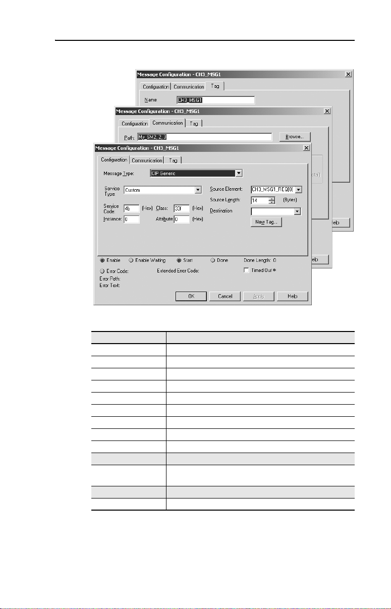
Understanding Explicit Messaging 5-11
Figure 5.8 RSLogix 5000 Modbus RTU Master Message Setup Screen
Table 5.E RSLogix 5000 Modbus RTU Master Message Configuration Data
Configuration Tab Description
Message Type Always use “CIP Generic.”
Service Type Type of Service to execute.
Service Code Code of the respective Service Type.
Class Class ID for the DSI Parameter Object.
Instance Instance number in the Class.
Attribute Attribute number of the Instance.
Source Element Source of the request service data.
Source Length Length of the request service data.
Destination Location where the response service data is stored.
Communication Tab Description
Path Format is <Name of Module>,2,n — where “n” equals the
Tag Tab Description
Name The name for the message instruction.
channel number (1…3) on the 1769-SM2.
Page 76

5-12 Understanding Explicit Messaging
RSLogix 500 Modbus RTU Master Write Message Example
Figure 5.9 shows an example Modbus RTU Master write message setup
screen. See Table 5.D for descriptions of the message configuration data.
Figure 5.9 RSLogix 500 Example Modbus RTU Master Write Message Setup Screen
In this example, Logic Command and Reference are being written to a
PowerFlex 70 drive. N7:100 through N7:106 (note the send length is 14
bytes or 7 words) contain the command data where:
Data Word Example Value Description
N7:100 15 PowerFlex 70 node address
N7:101 16 Function Code – Write Multiple Registers
N7:102 0 Starting Register Address (40001)
N7:103 3 Number of registers to write
N7:104 18 Value for 40001 – Logic Command word
N7:105 0 Value for 40002 – not used
N7:106 8192 Value for 40003 – Reference word
Note the Size in Bytes (Receive) is set to “0” because no data is returned
for a write message.
For additional information about Modbus RTU write messages for
PowerFlex 7-Class drives, refer to the 20-COMM-H Adapter User
Manual, publication 20COMM-UM009.
Page 77

Understanding Explicit Messaging 5-13
RSLogix 500 Modbus RTU Master Read Message Example
Figure 5.10 shows an example Modbus RTU Master read message setup
screen. See Table 5.D for descriptions of the message configuration data.
Figure 5.10 RSLogix 500 Example Modbus RTU Master Read Message Setup Screen
In this example, Logic Status and Feedback are being read from a
PowerFlex 70 drive. N7:110 through N7:113 (note the send length is 8
bytes or 4 words) contain the command data where:
Data Word Example Value Description
N7:110 15 PowerFlex 70 node address
N7:111 4 Function Code – Read Input Registers
N7:112 0 Starting Register Address (30001)
N7:113 3 Number of registers to read
N7:114 through N7:116 (note the Receive length is 6 bytes or 3 words)
contain the response data where:
Data Word Example Value Description
N7:114 3855 Value for 30001 – Logic Status word
N7:115 0 Value for 30002 – not used
N7:116 8192 Value for 30003 – Feedback word
For additional information about Modbus RTU read messages for
PowerFlex 7-Class drives, refer to the 20-COMM-H Adapter User
Manual, publication 20COMM-UM009.
Page 78

5-14 Understanding Explicit Messaging
RSLogix 5000 Modbus RTU Master Write Message Example
Figure 5.11 shows an example Modbus RTU Master write message setup
screen. See Table 5.E for descriptions of the message configuration data.
Figure 5.11 RSLogix 5000 Example Modbus RTU Master Write Message Setup Screen
In this example, Logic Command and Reference are being written to a
PowerFlex 70 drive. The CH3_MSG1_REQ array (14 bytes = 7 words)
contains the command data where:
Data Word Example Value Description
CH3_MSG1_REQ [0] 15 PowerFlex 70 node address
CH3_MSG1_REQ [1] 16 Function Code – Write Multiple Registers
CH3_MSG1_REQ [2] 0 Starting Register Address (40001)
CH3_MSG1_REQ [3] 3 Number of registers to write
CH3_MSG1_REQ [4] 18 Value for 40001 – Logic Command word
CH3_MSG1_REQ [5] 0 Value for 40002 – not used
CH3_MSG1_REQ [6] 8192 Value for 40003 – Reference word
A Destination element is not needed for a write message because no data
is returned.
For additional information about Modbus RTU write messages for
PowerFlex 7-Class drives, refer to the 20-COMM-H Adapter User
Manual, publication 20COMM-UM009.
Page 79

Understanding Explicit Messaging 5-15
RSLogix 5000 Modbus RTU Master Read Message Example
Figure 5.12 shows an example Modbus RTU Master read message setup
screen. See Table 5.E for descriptions of the message configuration data.
Figure 5.12 RSLogix 5000 Example Modbus RTU Master Read Message Setup Screen
In this example, Logic Status and Feedback are being read from a
PowerFlex 70 drive. The CH3_MSG2_REQ array (8 bytes = 4 words)
contains the command data where:
Data Word Example Value Description
CH3_MSG2_REQ [0] 15 PowerFlex 70 node address
CH3_MSG2_REQ [1] 4 Function Code – Read Input Registers
CH3_MSG2_REQ [2] 0 Starting Register Address (30001)
CH3_MSG2_REQ [3] 3 Number of registers to read
The CH3_MSG2_RESP array contains the response data where:
Data Word Example Value Description
CH3_MSG2_RESP [0] 3855 Value for 30001 – Logic Status word
CH3_MSG2_RESP [1] 0 Value for 30002 – not used
CH3_MSG2_RESP [2] 8192 Value for 30003 – Feedback word
For additional information about Modbus RTU read messages for
PowerFlex 7-Class drives, refer to the 20-COMM-H Adapter User
Manual, publication 20COMM-UM009.
Page 80

5-16 Understanding Explicit Messaging
Notes:
Page 81

Chapter 6
MicroLogix 1500 Example Ladder Programs
This chapter provides ladder examples for a MicroLogix 1500 controller
used with a 1769-SM2 module in Single mode and Multi-Drive mode.
Topic Page
Single Mode
Multi-Drive Mode 6-8
Single Mode
The ladder example provided in this section is based on a 1769-SM2
module in slot 1 with one PowerFlex 4/40 drive connected to each
channel (Figure 6.1). The ladder example demonstrates the following
functionality for each channel:
6-1
• Send a Logic Command to control the drive (for example, start, stop).
• Send a Reference to the drive and receive Feedback from the drive.
• Receive Logic Status information from the drive.
• Write and read parameters.
Explicit messaging (parameter read/write) capability varies between the
RSLogix software packages and controllers:
• Versions of RSLogix 500 before v6.30 do NOT support creating a
Message instruction for the 1769-SM2 module. This limits the
MicroLogix 1500 to performing I/O messaging (Logic Command/
Reference, and Logic Status/Feedback) only.
• RSLogix 500 v6.30 (or higher) must be used with a MicroLogix
1500 LRP Series C (or newer) controller to create Message
instructions to send explicit messages to the 1769-SM2 module.
Page 82

6-2 MicroLogix 1500 Example Ladder Programs
Figure 6.1 Example MicroLogix 1500 Single Mode System Arrangement
MicroLogix 1500 Controller
DSI
C
H
1
C
H
2
C
H
3
CH1
CH2
CH3
PowerFlex 4/40 Drives
PowerFlex 40 Drive Settings
The PowerFlex 40 drives used in the example program have the
following parameter settings:
Parameter Setting
P036 - [Start Source] 5 (Comm Port)
P038 - [Speed Reference] 5 (Comm Port)
A103 - [Comm Data Rate] 4 (19.2K)
A104 - [Comm Node Addr] 100
A107 - [Comm Format] 0 (RTU 8-N-1)
1769-SM2 Module Settings
The 1769-SM2 module used in the example program has the following
switch settings:
Switch Setting
Configuration Mode Switch (SW1) CONT position
Operating Mode Switch (SW2) 1X (Single) position
Page 83
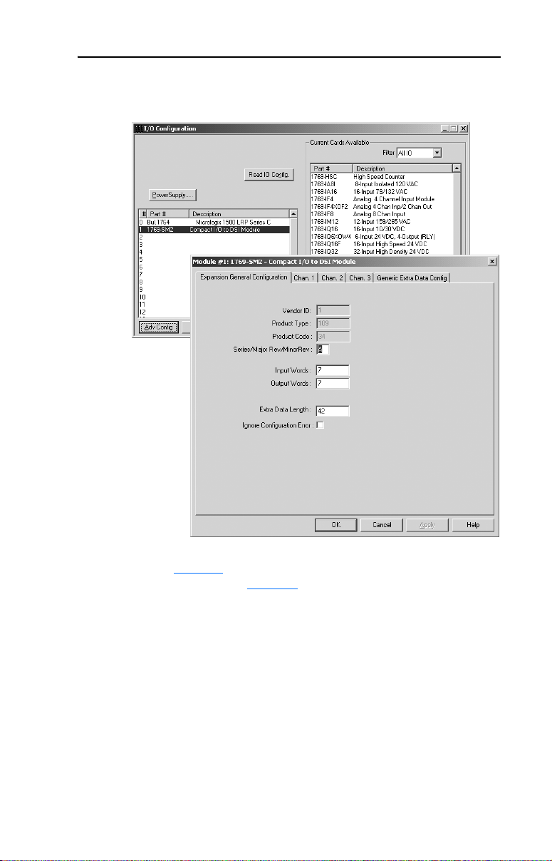
MicroLogix 1500 Example Ladder Programs 6-3
The I/O configuration in RSLogix 500 v6.30 (or higher) for the Single
mode example program is:
Refer to Table 3.C
descriptions. Also, see Chapter 4 for information about the I/O image,
Module Enable/Status, Logic Command/Status, and Reference/
Feedback.
for configuration data words and parameter
Page 84
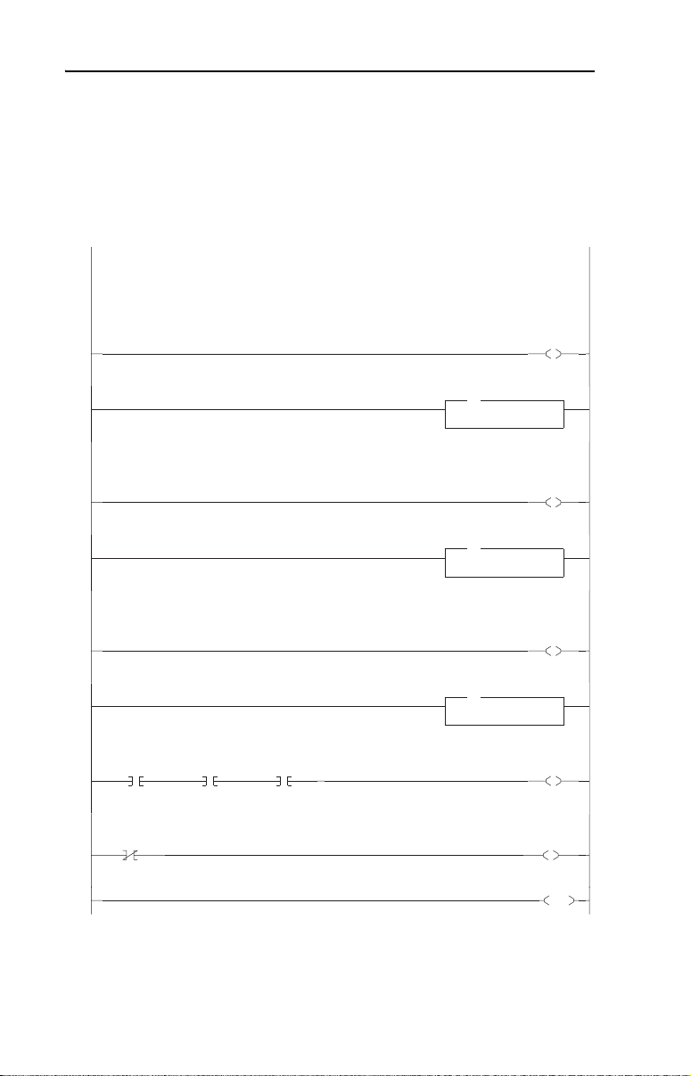
6-4 MicroLogix 1500 Example Ladder Programs
MicroLogix 1500 Example Program
Figure 6.2 Example MicroLogix 1500 Single Mode Ladder Logic Main Routine
In this Single mode example program, the channels are utilized as follows:
Channel 1 - Connected to 1 PowerFlex 4/40 drive (maximum allowed)
Channel 2 - Connected to 1 PowerFlex 4/40 drive (maximum allowed)
Channel 3 - Connected to 1 PowerFlex 4/40 drive (maximum allowed)
This rung enables the 1769-SM2 to send the Channel 1 Logic Command and Reference words to the drive.
0000
Channel 1 Subroutine
0001
This rung enables the 1769-SM2 to send the Channel 2 Logic Command and Reference words to the drive.
CH1
Drive 0
Logic Sts Valid
I:1
0
1769-SM2
1769-SM2
Config Data
Valid
I:1
15
1769-SM2
CH2
Drive 0
Logic Sts Valid
I:1
1769-SM2
0002
Channel 2 Subroutine
0003
This rung enables the 1769-SM2 to send the Channel 3 Logic Command and Reference words to the drive.
0004
Channel 3 Subroutine
0005
0006
0007
0008
MicroLogix 1500 w/ 1769-SM2 in Single mode
CH3
Drive 0
Logic Sts Valid
I:1
5
10
1769-SM2
Channel 1
Enable
1769-SM2
JSR
JSR
Jump To Subroutine
SBR File Number U:3
Channel 2
Enable
1769-SM2
JSR
JSR
Jump To Subroutine
SBR File Number U:4
Channel 3
Enable
1769-SM2
JSR
JSR
Jump To Subroutine
SBR File Number U:5
1769-SM2
Input Data
Valid
1769-SM2
Config Data
Error
O:1
0
O:1
1
O:1
2
B3:0
0
B3:0
1
END
Page 85
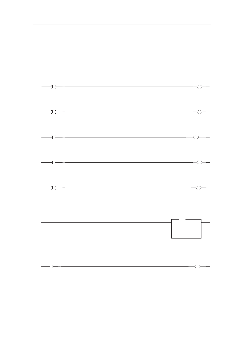
MicroLogix 1500 Example Ladder Programs 6-5
Figure 6.3 Example MicroLogix 1500 Single Mode Ladder Logic CH1 Subroutine
The following rungs display some of the Logic Status bits from the drive. Refer to Appendix D in the 1769-SM2 user manual for additional
information about the Logic Status word.
CH1 Drv0
Logic Sts
Bit 00
I:1
0000
0001
0002
0003
0004
0005
0006
16
1769-SM2
CH1 Drv0
Logic Sts
Bit 01
I:1
17
1769-SM2
CH1 Drv0
Logic Sts
Bit 03
I:1
19
1769-SM2
CH1 Drv0
Logic Sts
Bit 07
I:1
23
1769-SM2
CH1 Drv0
Logic Sts
Bit 08
1769-SM2
This rung displays the Feedback from the drive. An integer represents the xxx.x Hz format (decimal is implied) used by the drive, so a displayed
value of "300" equates to 30.0 Hz.
The following rungs display some of the Logic Command bits sent to the drive. Refer to Appendix D in the 1769-SM2 user manual for additional
information about the Logic Command word.
CH1
Drive 0
Stop
I:1
24
B3:2
0
1769-SM2 Channel 1 Subroutine
CH1
Drive 0
Feedback
MOV
MOV
Move
Source I:1.2
0<
Dest N7:1
CH1
Drive 0
Ready
B3:1
0
CH1
Drive 0
Active
B3:1
1
CH1
Drive 0
Running Fwd
B3:1
3
CH1
Drive 0
Fault
B3:1
7
CH1
Drive 0
At Speed
B3:1
8
0<
CH1 Drv0
Logic Cmd
Bit 00
O:1
16
1769-SM2
Page 86
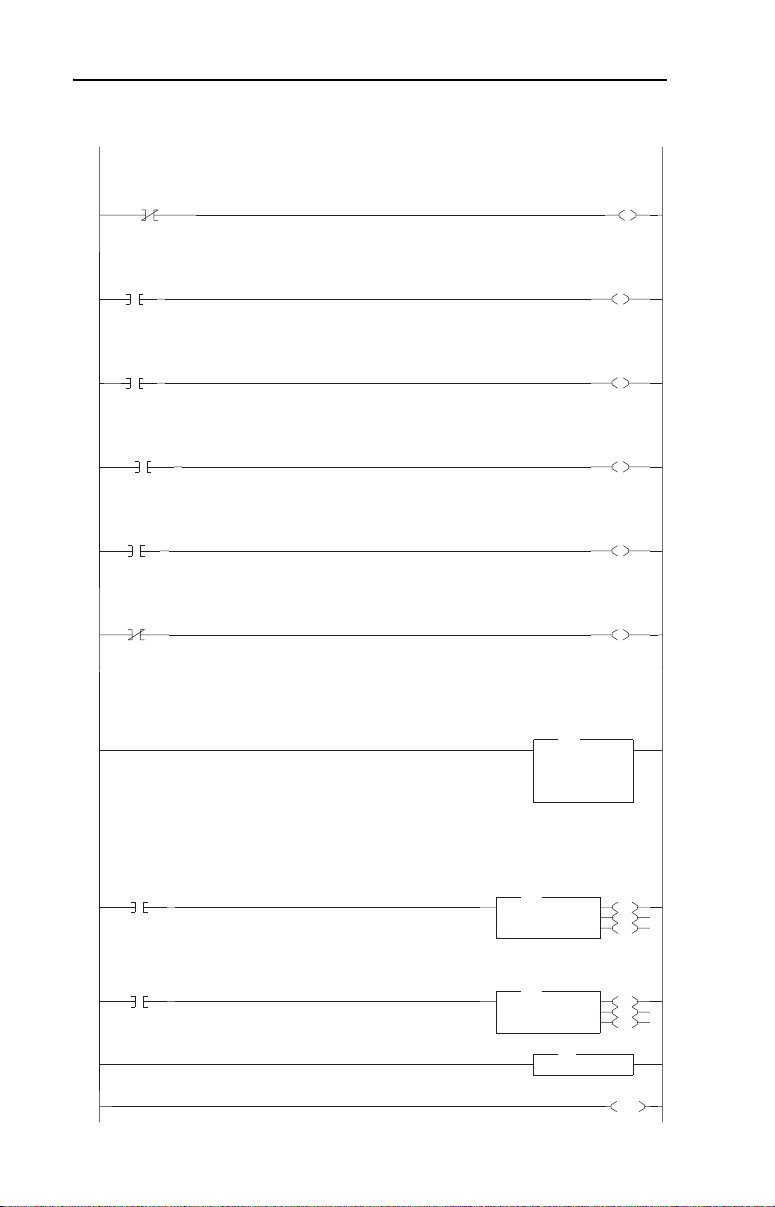
6-6 MicroLogix 1500 Example Ladder Programs
Figure 6.3 Example MicroLogix 1500 Single Mode Ladder Logic CH1 Subroutine (Continued)
This rung unlatches the contact that turns on the Start command when the drive is not communicating with the 1769-SM2. This prevents the drive
from immediately starting when communications is restored. If an immediate start is desired for the application, this rung could be deleted.
CH1
Drive 0
Logic Sts Valid
0007
0008
0009
0010
0011
0012
0013
0014
0015
0016
0017
I:1
0
1769-SM2
CH1
Drive 0
Start
B3:2
1
CH1
Drive 0
Jog
B3:2
2
CH1
Drive 0
Clear Faults
B3:2
3
CH1
Drive 0
Forward
B3:2
4
CH1
Drive 0
Forward
B3:2
4
This rung displays the Reference being sent to the drive. The data is used by the drive as xxx.x Hz format (decimal is implied), so entering a value
of "300" equates to 30.0 Hz.
CH1 Drv 0
Reference
Word
Move
Source N7:0
200<
Dest O:1.2
The following rungs are used to send explicit messages to the 1769-SM2 to read and write Parameter 78 [Jog Frequency] in PowerFlex 4/40 drives.
N7:2 = Write value
N7:3 = Read value
In Single mode, the desired parameter number is the value entered for the Target Device Instance number.
Read
Parameter
Request
B3:1
14
Write
Parameter
Request
B3:1
15
MSG
MSG
Read/Write Message
MSG File MG9:0
Setup Screen
MSG
MSG
Read/Write Message
MSG File MG9:1
Setup Screen
Return
MOV
MOV
RET
RET
CH1
Drive 0
Start
B3:2
CH1 Drv0
Logic Cmd
Bit 01
O:1
1769-SM2
CH1 Drv0
Logic Cmd
Bit 02
O:1
1769-SM2
CH1 Drv0
Logic Cmd
Bit 03
O:1
1769-SM2
CH1 Drv0
Logic Cmd
Bit 04
O:1
1769-SM2
CH1 Drv0
Logic Cmd
Bit 05
O:1
1769-SM2
200<
EN
DN
ER
EN
DN
ER
END
U
1
17
18
19
20
21
Page 87

MicroLogix 1500 Example Ladder Programs 6-7
The read and write message instructions for PowerFlex 40 drive
Parameter 78 - [Jog Frequency] are configured as follows:
Single Mode Example Program Data Table
Integer File N7: is used to contain the input and output data to/from the
three channels of the module:
N7: Word
DescriptionCH1 CH2 CH3
0 10 20 Reference
1 11 21 Feedback
2 12 22 Parameter 78 Write Value
3 13 23 Parameter 78 Read Value
Page 88

6-8 MicroLogix 1500 Example Ladder Programs
An example of data table values are shown below:
A value of “200” for the Reference equates to 20.0 Hz. A value of “100”
for drive Parameter 78 - [Jog Frequency] equates to 10.0 Hz.
Since CH2 and CH3 ladder routines are similar to the CH1 routine, they
are not provided.
Multi-Drive Mode
The ladder example provided in this section is based on a 1769-SM2
module in slot 1 with five PowerFlex 4/40 drives connected to CH1 and
to CH2, and one PowerFlex 70 connected to CH3 (Figure 6.4
ladder example demonstrates the following functionality for each
channel’s drives:
). The
• Send a Logic Command to control the drive (for example, start, stop).
• Send a Reference to the drive and receive Feedback from the drive.
• Receive Logic Status information from the drive.
• Write and read parameters.
Explicit messaging (parameter read/write) capability varies between the
RSLogix software packages and controllers:
• Versions of RSLogix 500 before v6.30 do NOT support creating a
Message instruction for the 1769-SM2 module. This limits the
MicroLogix 1500 to performing I/O messaging (Logic Command/
Reference, and Logic Status/Feedback) only.
• RSLogix 500 v6.30 (or higher) must be used with a MicroLogix
1500 LRP Series C (or newer) controller to create Message
instructions to send explicit messages to the 1769-SM2 module.
Page 89
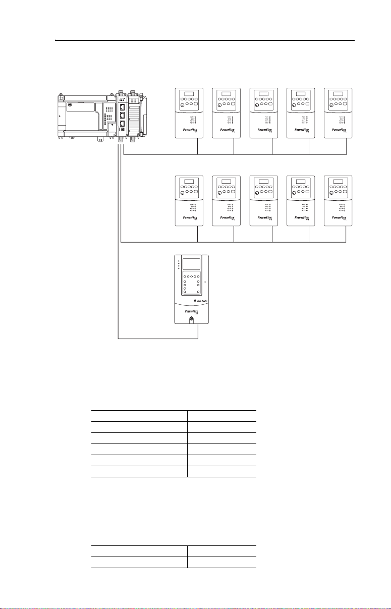
MicroLogix 1500 Example Ladder Programs 6-9
Figure 6.4 Example MicroLogix 1500 Multi-Drive Mode System Arrangement
MicroLogix 1500 Controller
DSI
C
H
1
C
H
2
C
H
3
PowerFlex 40 Settings
Up to 5 PowerFlex 4/40 Drives
CH1
Up to 5 PowerFlex 4/40 Drives
CH2
PowerFlex 70 Drive
with 20-COMM-H Adapter
CH3
The PowerFlex 40 drives used in the example program have the
following parameter settings:
Parameter Setting
P036 - [Start Source] 5 (Comm Port)
P038 - [Speed Reference] 5 (Comm Port)
A103 - [Comm Data Rate] 4 (19.2K)
A104 - [Comm Node Addr] 100…104
A107 - [Comm Format] 0 (RTU 8-N-1)
PowerFlex 70 Setting
The PowerFlex 70 drive used in the example program has the following
parameter setting:
Parameter Setting
90 - [Speed Ref A Sel] 22 (DPI Port 5)
Page 90

6-10 MicroLogix 1500 Example Ladder Programs
20-COMM-H Settings
The 20-COMM-H adapter used in the example program has the
following parameter and switch settings:
Parameter Settings
Parameter Setting
5 - [Net Rate Cfg] 2 (19200 Baud)
7 - [Net Parity Cfg] 1 (Odd)
16 - [DPI I/O Cfg] 00001 = Logic Command/Reference
30 - [Stop Bits Cfg] 0 (1 bit)
Switch Settings
Switch Setting
Node Address Switches 15
Network Protocol Switch RTU position
1769-SM2 Settings
The 1769-SM2 module used in the example program has the following
switch settings:
Switch Setting
Configuration Mode Switch (SW1) CONT position
Operating Mode Switch (SW2) 5X (Multi-Drive) position
Page 91
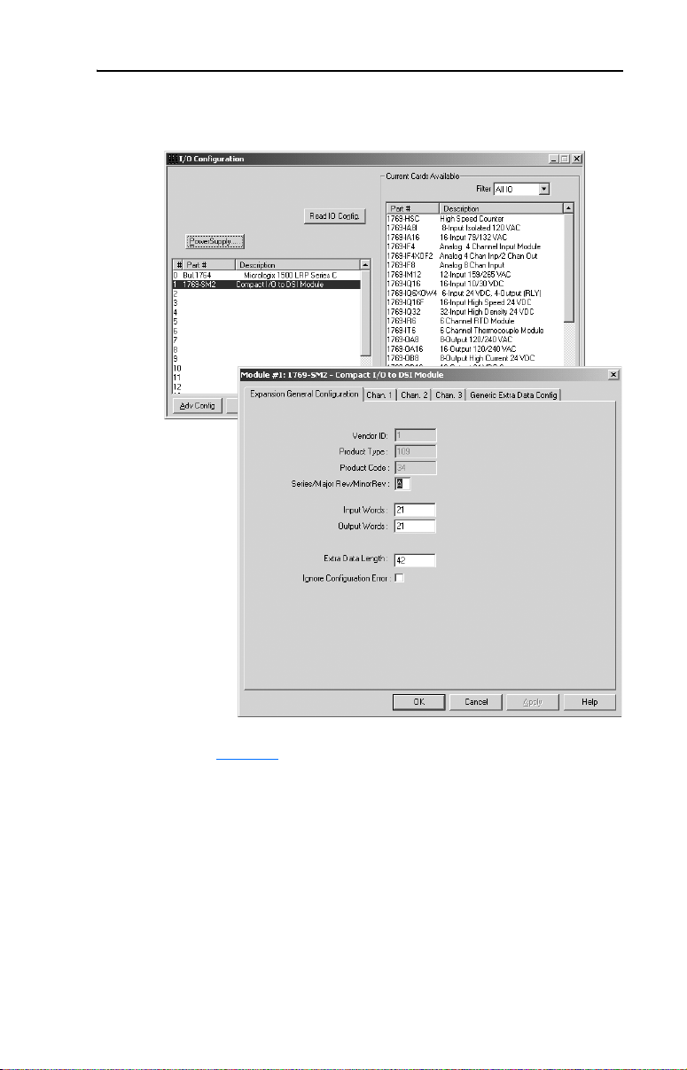
MicroLogix 1500 Example Ladder Programs 6-11
The I/O configuration in RSLogix 500 v6.30 (or higher) for the
Multi-Drive mode example program is:
Refer to Chapter 4
Status, Logic Command/Status, and Reference/Feedback.
for information about the I/O image, Module Enable/
Page 92

6-12 MicroLogix 1500 Example Ladder Programs
MicroLogix 1500 Multi-Drive Mode Example Program
Figure 6.5 Example MicroLogix 1500 Multi-Drive Ladder Logic Main Routine
In this Multi-Drive example program, the channels are utilized as follows:
Channel 1 - Connected to 5 PowerFlex 4/40 drives (maximum allowed)
Channel 2 - Connected to 5 PowerFlex 4/40 drives (maximum allowed)
Channel 3 - Configured for Modbus RTU Master mode and connected to 1 PowerFlex 70 drive (with 20-COMM-H adapter)
This rung enables the 1769-SM2 to send the Channel 1 Logic Command and Reference words to the drives.
0000
Channel 1 Drive 0 Subroutine
0001
Channel 1 Drive 1 Subroutine
0002
Channel 1 Drive 2 Subroutine
0003
Channel 1 Drive 3 Subroutine
0004
Channel 1 Drive 4 Subroutine
0005
This rung enables the 1769-SM2 to send the Channel 2 Logic Command and Reference words to the drives.
0006
Channel 2 Drive 0 Subroutine
0007
Channel 2 Drive 1 Subroutine
0008
MicroLogix 1500 w/ 1769-SM2 in Multi-Drive mode
Channel 1
Enable
1769-SM2
JSR
JSR
Jump To Subroutine
SBR File Number U:3
JSR
JSR
Jump To Subroutine
SBR File Number U:4
JSR
JSR
Jump To Subroutine
SBR File Number U:5
JSR
JSR
Jump To Subroutine
SBR File Number U:6
JSR
JSR
Jump To Subroutine
SBR File Number U:7
Channel 2
Enable
1769-SM2
JSR
JSR
Jump To Subroutine
SBR File Number U:8
JSR
JSR
Jump To Subroutine
SBR File Number U:9
O:1
0
O:1
1
Page 93

MicroLogix 1500 Example Ladder Programs 6-13
Figure 6.5 Example MicroLogix 1500 Multi-Drive Ladder Logic Main Routine (Continued)
Channel 2 Drive 2 Subroutine
0009
Channel 2 Drive 3 Subroutine
0010
Channel 2 Drive 4 Subroutine
0011
Channel 3 Modbus RTU Master Subroutine
0012
CH1
Drive 0
Logic Sts Valid
0013
0014
0015
0016
0017
I:1
0
1769-SM2
CH2
Drive 0
Logic Sts Valid
I:1
5
1769-SM2
1769-SM2
CH1 Input Data
Valid
B3:0
2
1769-SM2
Config Data
Valid
I:1
15
1769-SM2
CH1
Drive 1
Logic Sts Valid
I:1
1
1769-SM2
CH2
Drive 1
Logic Sts Valid
I:1
6
1769-SM2
1769-SM2
CH2 Input Data
Valid
B3:0
3
CH1
Drive 2
Logic Sts Valid
I:1
2
1769-SM2
CH2
Drive 2
Logic Sts Valid
I:1
7
1769-SM2
CH1
Drive 3
Logic Sts Valid
I:1
3
1769-SM2
CH2
Drive 3
Logic Sts Valid
I:1
8
1769-SM2
CH1
Drive 4
Logic Sts Valid
I:1
4
1769-SM2
CH2
Drive 4
Logic Sts Valid
I:1
9
1769-SM2
JSR
JSR
Jump To Subroutine
SBR File Number U:10
JSR
JSR
Jump To Subroutine
SBR File Number U:11
JSR
JSR
Jump To Subroutine
SBR File Number U:12
JSR
JSR
Jump To Subroutine
SBR File Number U:13
1769-SM2
CH1 Input Data
Valid
B3:0
2
1769-SM2
CH2 Input Data
Valid
B3:0
3
1769-SM2
All Input Data
Valid
B3:0
1769-SM2
Config Data
Error
B3:0
0
1
END
Page 94

6-14 MicroLogix 1500 Example Ladder Programs
Figure 6.6 Example MicroLogix 1500 Multi-Drive Ladder Logic CH1 Drive 0 Subroutine
The following rungs display some of the Logic Status bits from the drive. Refer to Appendix D in the 1769-SM2 user manual for additional
information about the Logic Status word.
CH1 Drv0
Logic Sts
Bit 00
I:1
0000
0001
0002
0003
0004
0005
0006
16
1769-SM2
CH1 Drv0
Logic Sts
Bit 01
I:1
17
1769-SM2
CH1 Drv0
Logic Sts
Bit 03
I:1
19
1769-SM2
CH1 Drv0
Logic Sts
Bit 07
I:1
23
1769-SM2
CH1 Drv0
Logic Sts
Bit 08
I:1
24
1769-SM2
This rung displays the Feedback from the drive. An integer represents the xxx.x Hz format (decimal is implied) used by the drive, so a displayed
value of "300" equates to 30.0 Hz.
The following rungs display some of the Logic Command bits from the drive. Refer to Appendix D in the 1769-SM2 user manual for additional
information about the Logic Command word.
CH1
Drive 0
Stop
B3:11
0
1769-SM2 Channel 1 Drive 0 Subroutine
CH1
Drive 0
Feedback
MOV
MOV
Move
Source I:1.2
101<
Dest N7:1
CH1
Drive 0
Ready
B3:10
0
CH1
Drive 0
Active
B3:10
1
CH1
Drive 0
Running Fwd
B3:10
3
CH1
Drive 0
Fault
B3:10
7
CH1
Drive 0
At Speed
B3:10
8
101<
CH1 Drv0
Logic Cmd
Bit 00
O:1
16
1769-SM2
Page 95

MicroLogix 1500 Example Ladder Programs 6-15
Figure 6.6 Example MicroLogix 1500 Multi-Drive Ladder Logic CH1 Drive 0 Subroutine (Continued)
This rung unlatches the contact that turns on the Start command when the drive is not communicating with the 1769-SM2. This prevents the drive
from immediately starting when communications is restored. If an immediate start is desired for the application, this rung could be deleted.
CH1
Drive 0
Logic Sts Valid
0007
0008
0009
0010
0011
0012
0013
0014
0015
0016
I:1
0
1769-SM2
CH1
Drive 0
Start
B3:11
1
CH1
Drive 0
Jog
B3:11
2
CH1
Drive 0
Clear Faults
B3:11
3
CH1
Drive 0
Forward
B3:11
4
CH1
Drive 0
Forward
B3:11
4
This rung displays the Reference being sent to the drive. The data is used by the drive as xxx.x Hz format (decimal is implied), so entering a value
of "300" equates to 30.0 Hz.
The following rungs are used to send explicit messages to the 1769-SM2 to read and write Parameter 78 [Jog Frequency] in PowerFlex 4/40 drives.
N7:2 = Write value
N7:3 = Read value
In Single mode, the desired parameter number is the value entered for the Target Device Instance number.
Read
Parameter
Request
B3:11
14
Write
Parameter
Request
B3:11
15
CH1
Drive 0
Reference
Move
Source N7:0
101<
Dest O:1.2
MSG
MSG
Read/Write Message
MSG File MG9:0
Setup Screen
MSG
MSG
Read/Write Message
MSG File MG9:1
Setup Screen
Return
MOV
MOV
RET
RET
CH1
Drive 0
Start
B3:11
U
1
CH1 Drv0
Logic Cmd
Bit 01
O:1
17
1769-SM2
CH1 Drv0
Logic Cmd
Bit 02
O:1
18
1769-SM2
CH1 Drv0
Logic Cmd
Bit 03
O:1
19
1769-SM2
CH1 Drv0
Logic Cmd
Bit 04
O:1
20
1769-SM2
CH1 Drv0
Logic Cmd
Bit 05
O:1
21
1769-SM2
101<
EN
DN
ER
EN
DN
ER
0017
END
Page 96

6-16 MicroLogix 1500 Example Ladder Programs
The read and write message instructions for PowerFlex 40 drive
Parameter 78 - [Jog Frequency] are configured as follows:
For additional information about the message setup, refer to page 5-3
Multi-Drive Example Program Data Tables
Integer File N7: is used to contain the input and output data to/from the
three channels:
N7: Words for CH1
0 10203040Reference
1 11 21 31 41 Feedback
2 12 22 32 42 Parameter 78 Write Value
3 13 23 33 43 Parameter 78 Read Value
DescriptionDrive 0 Drive 1 Drive 2 Drive 3 Drive 4
.
Page 97
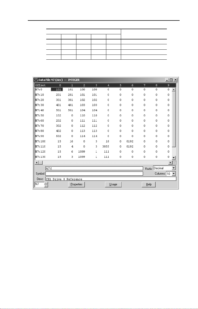
MicroLogix 1500 Example Ladder Programs 6-17
N7: Words for CH2
DescriptionDrive 0 Drive 1 Drive 2 Drive 3 Drive 4
50 60 70 80 90 Reference
51 61 71 81 91 Feedback
52 62 72 82 92 Parameter 78 Write Value
53 63 73 83 93 Parameter 78 Read Value
An example of data table values are shown below:
A value of “101” for the Reference equates to 10.1 Hz. A value of “100”
for drive Parameter 78 - [Jog Frequency] equates to 10.0 Hz.
Since the Drive 1…4 and CH2 ladder routines are similar to the CH1
Drive 0 routine, they are not provided.
Page 98
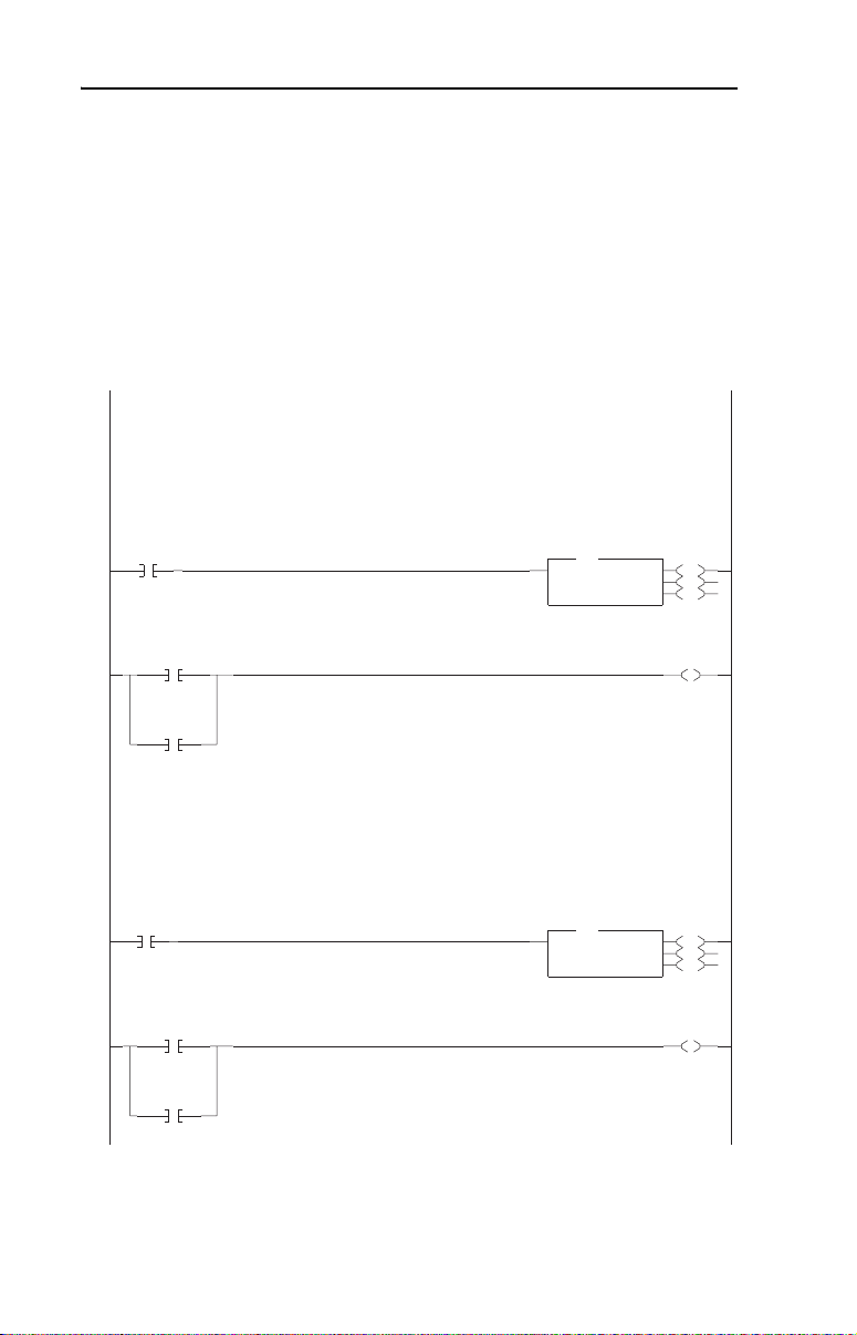
6-18 MicroLogix 1500 Example Ladder Programs
CH3 Modbus RTU Master Subroutine Example
In Multi-Drive mode, any channel can be configured for Modbus RTU
Master operation. In the MicroLogix 1500 Multi-Drive ladder logic
example, CH3 is used to communicate with a PowerFlex 70 drive via
Modbus RTU operation.
Figure 6.7 Example MicroLogix 1500 Modbus RTU Ladder Logic CH3 Subroutine
Channel 3 consists of a single PowerFlex 70 drive with a 20-COMM-H adapter.
Write Logic Command and Reference.
N7:100 = Slave Address ("15" is the 20-COMM-H address)
N7:101 = Function Code ("16" is Write Multiple Registers command)
N7:102 = Starting Address ("0" = 4x0001)
N7:103 = Length ("3")
N7:104 = Logic Command word
N7:105 = MSW of 32-bit Reference
N7:106 = 16-bit Reference or LSW of 32-bit Reference
CH3
Write
Control
B3:30
0000
0
CH3
Read
Status
B3:30
1
Message
Done
MG9:20
DN
Message
Error
MG9:20
ER
Message
Done
MG9:21
DN
Message
Error
MG9:21
ER
Execute the control message continuously if the CH3 Write Control bit (B3:30/0) is ON.
0001
Read Logic Status and Feedback.
N7:110 = Slave Address ("15" is the 20-COMM-H address)
N7:111 = Function Code ("4" is Read Input Registers command)
N7:112 = Starting Address ("0" = 3x0001)
N7:113 = Length ("3")
The response data is stored in:
N7:114 = Logic Status word
N7:115 = MSW of 32-bit Feedback
N7:116 = 16-bit Feedback or LSW of 32-bit Feedback
0002
Execute the status message continuously if the CH3 Read Status bit (B3:30/1) is ON.
0003
1769-SM2 Channel 3 Modbus RTU Master Subroutine
MSG
MSG
Read/Write Message
MSG File MG9:20
Setup Screen
MSG
MSG
Read/Write Message
MSG File MG9:21
Setup Screen
EN
DN
ER
Message
Enable
MG9:20
U
EN
EN
DN
ER
Message
Enable
MG9:21
U
EN
Page 99
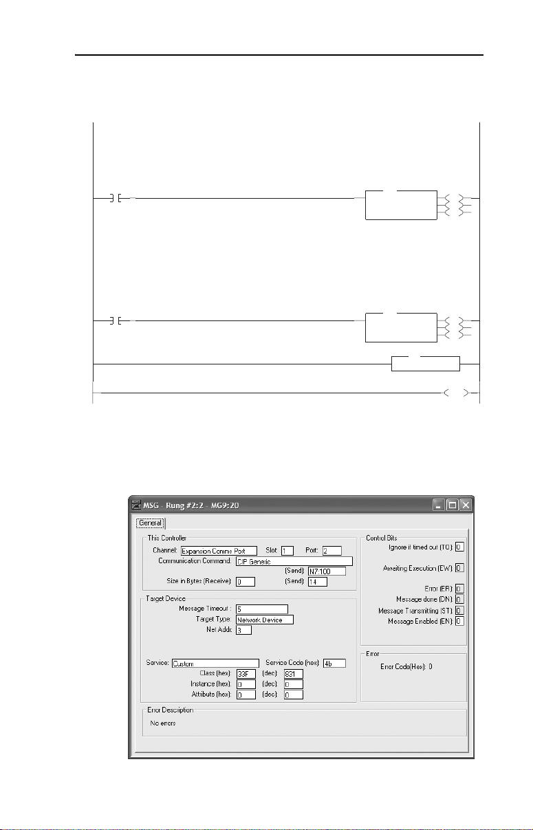
MicroLogix 1500 Example Ladder Programs 6-19
Figure 6.7 Example MicroLogix 1500 Modbus RTU Ladder Logic CH3 Subroutine (Continued)
Write Parameter 100 [Jog Frequency] (written 1x per request).
N7:120 = Slave Address ("15" is the 20-COMM-H address)
N7:121 = Function Code ("6" is Write Single Register command)
N7:122 = Starting Address ("1099" = 4x1100)
N7:123 = Length ("1")
N7:124 = Pr. 100 [Jog Frequency] Write Value
CH3
Write
Pr.100
B3:30
0004
2
Read Parameter 100 [Jog Frequency] (read 1x per request).
N7:130 = Slave Address ("15" is the 20-COMM-H address)
N7:131 = Function Code ("3" is Read Holding Register command)
N7:132 = Starting Address ("1099" = 4x1100)
N7:133 = Length ("1")
The response data is stored in:
N7:134 = Pr. 100 [Jog Frequency] Read Value
CH3
Read
Pr.100
B3:30
0005
3
0006
0007
MSG
MSG
Read/Write Message
MSG File MG9:22
Setup Screen
MSG
MSG
Read/Write Message
MSG File MG9:23
Setup Screen
RET
RET
Return
EN
DN
ER
EN
DN
ER
END
The Logic Command/Reference write message instruction on rung 0000
is configured as follows:
Page 100

6-20 MicroLogix 1500 Example Ladder Programs
The format of the command data is:
Data Word Example Value Description
N7:100 15 PowerFlex 70 node address
N7:101 16 Function Code – Write Multiple Registers
N7:102 0 Starting Register Address (40001)
N7:103 3 Number of registers to write
N7:104 18 Value for 40001 – Logic Command word
N7:105 0 Value for 40002 – not used
N7:106 8192 Value for 40003 – Reference word
The Logic Status/Feedback read message instruction on rung 0002 is
configured as follows:
The format of the command data is:
Data Word Example Value Description
N7:110 15 PowerFlex 70 node address
N7:111 4 Function Code – Read Input Registers
N7:112 0 Starting Register Address (30001)
N7:113 3 Number of registers to read
The format of the response data is:
Data Word Example Value Description
N7:114 3855 Value for 30001 – Logic Status word
N7:115 0 Value for 30002 – not used
N7:116 8192 Value for 30003 – Feedback word
 Loading...