

Page 1

Installation Instructions
Compact I/O DeviceNet Scanner Module
(Cat. No. 1769-SDN)
Inside...
For More Information.............................................................................. 2
European Communities (EC) Directive Compliance ................................ 3
Hazardous Location Considerations ....................................................... 4
Environnements dangereux .................................................................... 4
Module Description ................................................................................ 5
Module Installation................................................................................. 6
System Planning ..................................................................................... 8
System Assembly.................................................................................... 9
System Mounting.................................................................................. 10
Replacing the Scanner Module within a System ................................. 13
Field Wiring Connections ...................................................................... 14
Scanner Module Power-Up ................................................................... 15
Configuring the 1769-SDN on DeviceNet............................................. 16
Data Organization................................................................................. 17
Diagnostic Indicators ............................................................................ 18
Error Codes............................................................................................ 19
Specifications ....................................................................................... 21
Publication 1769-IN060C-EN-P - May 2002
Page 2

2 Compact I/O DeviceNet Scanner Module
TIP
For More Information
For Refer to this Document Pub. No.
A more detailed description of how to use
your DeviceNet Scanner Module
Detailed information on planning,
mounting, wiring, and troubleshooting your
CompactLogix System.
Detailed information on planning,
mounting, wiring, and troubleshooting your
MicroLogix 1500 System.
DeviceNet network planning information. DeviceNet Cable System Planning and
More information on proper wiring and
grounding techniques.
If you would like a manual, you can:
• download a free electronic version from the internet:
www.theautomationbookstore.com
• purchase a printed manual by:
– contacting your local distributor or Rockwell Automation representative
– visiting www.theautomationbookstore.com and placing your order
– calling 1.800.963.9548 (USA/Canada)
or 001.330.725.1574 (Outside USA/Canada)
Compact I/O DeviceNet Scanner
Module User Manual
CompactLogix System User Manual 1769-UM007C-EN-P
MicroLogix 1500 Programmable
Controllers User Manual
Installation Manual
Industrial Automation Wiring and
Grounding Guidelines
1769-UM009A-EN-P
1764-UM001A-US-P
DN-6.7.2
1770-4.1
Translated versions of these Installation Instructions are
available electronically. Obtain a translated version of this
publication at www.theautomationbookstore.com.
Publication 1769-IN060C-EN-P - May 2002
Page 3

Compact I/O DeviceNet Scanner Module 3
European Communities (EC) Directive Compliance
This product carries the CE mark and is approved for installation within the
European Union and EEA regions. It has been designed and tested to meet the
following directives.
EMC Directive
This product is tested to meet the Council Directive 89/336/EC Electromagnetic
Compatibility (EMC) by applying the following standards, in whole or in part,
documented in a technical construction file:
• EN 50081-2 EMC — Generic Emission Standard, Part 2 — Industrial
Environment
• EN 50082-2 EMC — Generic Immunity Standard, Part 2 — Industrial
Environment
This product is intended for use in an industrial environment.
Low Voltage Directive
This product is tested to meet Council Directive 73/23/EEC Low Voltage, by
applying the safety requirements of EN 61131-2 Programmable Controllers, Part 2 Equipment Requirements and Tests. For specific information required by
EN 61131-2, see the appropriate sections in this publication, as well as the
Allen-Bradley publication Industrial Automation Wiring and Grounding Guidelines
For Noise Immunity, publication 1770-4.1. and the Automation Systems Catalog,
B111.
This equipment is classified as open equipment and must be mounted in an
enclosure during operation to provide safety protection.
Publication 1769-IN060C-EN-P - May 2002
Page 4
4 Compact I/O DeviceNet Scanner Module
WARNING
!
AVERTISSEMENT
!
Hazardous Location Considerations
This equipment is suitable for use in Class I, Division 2, Groups A, B, C, D or
non-hazardous locations only. The following WARNING statement applies to use in
hazardous locations.
EXPLOSION HAZARD
• Substitution of components may impair suitability for Class
I, Division 2.
• Do not replace components or disconnect equipment
unless power has been switched off or the area is known
to be non-hazardous.
• Do not connect or disconnect components unless power
has been switched off or the area is known to be
non-hazardous.
• This product must be installed in an enclosure. All cables
connected to the product must remain in the enclosure or
be protected by conduit or other means.
• All wiring must comply with N.E.C. article 501-4(b).
Environnements dangereux
Cet équipement est conçu pour être utilisé dans des environnements de Classe 1,
Division 2, Groupes A, B, C, D ou non dangereux. La mise en garde suivante
s’applique à une utilisation dans des environnements dangereux.
Publication 1769-IN060C-EN-P - May 2002
DANGER D’EXPLOSION
• La substitution de composants peut rendre cet équipement
impropre à une utilisation en environnement de Classe 1,
Division 2.
• Ne pas remplacer de composants ou déconnecter
l'équipement sans s'être assuré que l'alimentation est
coupée et que l'environnement est classé non dangereux.
• Ne pas connecter ou déconnecter des composants sans
s'être assuré que l'alimentation est coupée ou que
l'environnement est classé non dangereux.
• Ce produit doit être installé dans une armoire.
Page 5
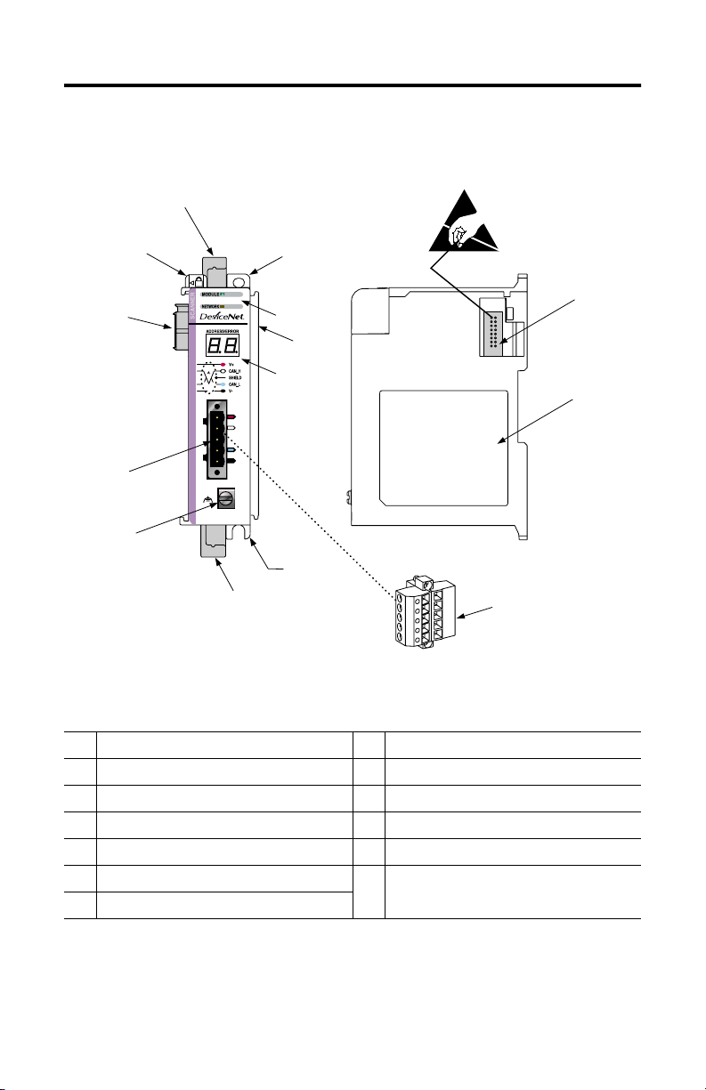
Module Description
2A
Compact I/O DeviceNet Scanner Module 5
1
8A
3A
4
8B
5
7A
6
3B
2B
7B
Table A
1 bus lever (with locking function) 6 grounding screw
2A upper DIN rail latch 7A DeviceNet mating male receptacle
2B lower DIN rail latch 7B removable DeviceNet female connector
3A upper panel mounting tab 8A movable bus connector with female pins
3B lower panel mounting tab 8B bus connector with male pins
4 Module and Network status LEDs 9 nameplate label
5 Address and Error numeric displays
8B
9
Publication 1769-IN060C-EN-P - May 2002
Page 6
6 Compact I/O DeviceNet Scanner Module
ATTENTION
!
Module Installation
The 1769-SDN module is suitable for use in an industrial environment when
installed in accordance with these instructions. Specifically, this equipment is
intended for use in clean, dry environments (Pollution Degree 2
circuits not exceeding Over Voltage Category II
(2)
(IEC 60664-1).
Prevent Electrostatic Discharge
Electrostatic discharge can damage integrated circuits or
semiconductors if you touch bus connector pins. Follow these
guidelines when you handle the module:
• Touch a grounded object to discharge static potential.
• Wear an approved wrist-strap grounding device.
• Do not touch the bus connector or connector pins.
• Do not touch circuit components inside the module.
• If available, use a static-safe work station.
• When not in use, keep the module in its static-shield box.
(1)
) and with
(3)
(1)
Pollution Degree 2 is an environment where, normally, only non-conductive pollution occurs except that occasionally a
temporary conductivity caused by condensation shall be expected.
(2)
Over Voltage Category II is the load level section of the electrical distribution system. At this level transient voltages are
controlled and do not exceed the impulse voltage capability of the product’s insulation.
(3)
Pollution Degree 2 and Over Voltage Category II are International Electrotechnical Commission (IEC) designations.
Publication 1769-IN060C-EN-P - May 2002
Page 7

Remove Power
ATTENTION
!
Compact I/O DeviceNet Scanner Module 7
Remove power before removing or inserting this module. When
you remove or insert a module with power applied, an
electrical arc may occur. An electrical arc can cause personal
injury or property damage by:
• sending an erroneous signal to your system’s field devices,
causing unintended machine motion
• causing an explosion in a hazardous environment
Electrical arcing causes excessive wear to contacts on both the
module and its mating connector. Worn contacts may create
electrical resistance.
Publication 1769-IN060C-EN-P - May 2002
Page 8

8 Compact I/O DeviceNet Scanner Module
System Planning
Consider the following when planning your system:
• The scanner can communicate with up to 63 DeviceNet devices.
• The scanner, as a master, can own up to 63 slave I/O nodes.
• The scanner can simultaneously be a master and be a slave owned by
another DeviceNet master.
• A 1769-ECR (right end cap) or 1769-ECL (left end cap) is required to
terminate the end of the Compact I/O bus.
• Each bank of Compact I/O must have its own power supply (a MicroLogix
1500 acts as the power supply for modules directly connected to it).
• A Compact I/O power supply, or MicroLogix 1500 Base Unit, has limits in
the amount of +5V dc and +24V dc current it can supply to modules in its
I/O bank. These limits depend on the catalog number (e.g. 1769-PA2) of the
supply. A bank of modules must not exceed the current limits of the I/O
bank power supply or MicroLogix 1500 Base Unit.
Refer to the Compact 1769 Expansion I/O Power Supplies Installation
Instructions, publication 1769-5.14 or the MicroLogix 1500 User Manual,
publication 1764-UM001A-EN-P.
• The scanner has a distance rating of four, therefore the scanner must be
within four modules of the I/O bank’s power supply.
• Determine the DeviceNet baud rate based on standard DeviceNet
considerations.
• Consider the number of words of I/O data the host controller supports.
For more information on planning your DeviceNet network, refer to the DeviceNet
Cable System Planning and Installation Manual, publication DN-6.7.2.
Publication 1769-IN060C-EN-P - May 2002
Page 9

Compact I/O DeviceNet Scanner Module 9
ATTENTION
!
System Assembly
The module can be attached to an adjacent controller, power supply, or I/O
module. For mounting instructions, see “Panel Mounting” on page 10, or “DIN Rail
Mounting” on page 12. To work with a system that is already mounted, see
“Replacing a Single Module within a System” on page 13.
The following procedure shows you how to assemble the Compact I/O system.
A
C
1. Disconnect power.
2. Check that the bus lever of the module (A) is in the unlocked (fully right)
position.
3. Use the upper and lower tongue-and-groove slots (B) to secure the modules
together.
4. Move the module back along the tongue-and-groove slots until the bus
connectors (C) line up with each other.
5. Use your fingers or a small screw driver to push the bus lever back slightly
to clear the positioning tab (D).
6. Move the module’s bus lever fully to the left (E) until it clicks. Ensure it is
locked firmly in place.
B
B
D
E
G
F
When attaching I/O modules, it is very important that the
bus connectors are securely locked together to ensure
proper electrical connection.
Publication 1769-IN060C-EN-P - May 2002
Page 10

10 Compact I/O DeviceNet Scanner Module
ATTENTION
!
7. Attach an end cap terminator (F) to the last module in the system by using
the tongue-and-groove slots as before.
8. Lock the end cap bus terminator (G).
IMPORTANT
A 1769-ECR or 1769-ECL right or left end cap must be used to
terminate the end of the serial communication bus.
System Mounting
During panel or DIN rail mounting of all devices, be sure that
all debris (metal chips, wire strands, etc.) is kept from falling
into the module. Debris that falls into the module could cause
damage on power up.
Minimum Spacing
Compact I/O
Top
Compact I/O
Bottom
Compact I/O
Compact I/O
Maintain spacing from
enclosure walls,
wireways, adjacent
equipment, etc. Allow 50
mm (2 in.) of space on all
sides for adequate
ventilation, as shown:
Allow at least 110 mm
(4.33 in.) of enclosure depth to accommodate the module and the DeviceNet
connector.
Side
Controller
Panel Mounting
Mount the module to a panel using two screws per module. Use M4 or #8 panhead
screws. Mounting screws are required on every module.
Publication 1769-IN060C-EN-P - May 2002
Side
Compact I/O
End Cap or Cable
Page 11

Compact I/O DeviceNet Scanner Module 11
Panel Mounting Using the Dimensional Drawing
NOTE: All dimensions are in mm (inches). Hole spacing tolerance: ±0.04 mm (0.016 in.).
Compact I/O with CompactLogix Controller and Power Supply
Mounting Hole
Dimension
132 mm (5.19 in)
122.6 mm (4.83 in)
59 mm
59 mm
(2.32 in)
(2.32 in)
(1.97 in)
40 mm
(1.58 in)
118 mm (4.65 in)
35 mm
(1.38 in)
35 mm
50 mm
(1.38 in)
DIN Rail
Center Line
Compact I/O with MicroLogix 1500 Base Unit and Processor
168 mm
Mounting Hole
Dimension
59 mm
(2.32 in)
(6.62 in)
147 mm
(5.79 in)
35 mm
(1.38 in)
70 mm
(2.76 in)
(1.38 in)
14.7 mm
(0.58 in)
35 mm
35 mm
(1.38 in)
35 mm
(1.38 in)
35 mm
(1.38 in)
35 mm
(1.38 in)
28.5 mm
(1.12 in)
147.4 mm (5.81 in)
28.5 mm
(1.12 in)
132 mm (5.19 in)
122.6 mm (4.83 in)
59 mm
(2.32 in)
118 mm (4.65 in)
DIN Rail
Center Line
13.5 mm
(0.53 in)
14.7 mm
(0.58 in)
Publication 1769-IN060C-EN-P - May 2002
147.4 mm (5.81 in)
Page 12

12 Compact I/O DeviceNet Scanner Module
Panel Mounting Procedure Using Modules as a Template
The following procedure allows you to use the assembled modules as a template
for drilling holes in the panel. Due to module mounting hole tolerance, it is
important to follow these procedures:
1. On a clean work surface, assemble no more than three modules.
2. Using the assembled modules as a template, carefully mark the center of all
module-mounting holes on the panel.
3. Return the assembled modules to the clean work surface, including any
previously mounted modules.
4. Drill and tap the mounting holes for the recommended M4 or #8 screw.
5. Place the modules back on the panel, and check for proper hole alignment.
6. Attach the modules to the panel using the mounting screws.
7. Repeat steps 1 to 6 for any remaining modules.
DIN Rail Mounting
The module can be mounted using the following DIN rails: 35 x 7.5 mm (EN 50 022
- 35 x 7.5) or 35 x 15 mm (EN 50 022 - 35 x 15).
Before mounting the module on a DIN rail, close the DIN rail latches. Press the DIN
rail mounting area of the module against the DIN rail. The latches will momentarily
open and lock into place. DIN rail mounting dimensions are shown below.
Dimension Height
B
A
C
Publication 1769-IN060C-EN-P - May 2002
A 118 mm
B 59 mm
C 59 mm
(4.65 in.)
(2.325 in.)
(2.325 in.)
Page 13

Compact I/O DeviceNet Scanner Module 13
TIP
Replacing the Scanner Module within a System
The scanner can be replaced while the system is mounted to a panel (or DIN rail).
1. Remove power. See important note on page 7.
2. Remove the DeviceNet cable from the scanner by removing the DeviceNet
connector.
3. Remove the upper and lower mounting screws from the scanner (or open
the DIN latches using a flat-blade screwdriver).
4. On the scanner to be replaced and the right-side adjacent module (or end
cap if the scanner is the last module in the bank), move the bus levers to the
right (unlock) to disconnect the scanner from the adjacent modules.
5. Gently slide the disconnected scanner module forward.
If you feel excessive resistance, make sure that you disconnected the
scanner from the bus and that you removed both mounting screws (or
opened the DIN latches).
.
It may be necessary to rock the scanner slightly from
front to back to remove it, or, in a panel-mounted
system, to loosen the screws of adjacent modules.
6. Before installing the replacement scanner, be sure that the bus lever on the
right-side adjacent module is in the unlocked (fully right) position.
7. Slide the replacement scanner into the open slot.
8. Connect the scanner and modules together by locking (fully left) the bus
levers on the replacement scanner and the right-side adjacent module or end
cap.
9. Replace the mounting screws (or snap the scanner onto the DIN rail).
10. Replace the DeviceNet cable on the scanner by attaching the connector to
the scanner.
Publication 1769-IN060C-EN-P - May 2002
Page 14

14 Compact I/O DeviceNet Scanner Module
ATTENTION
!
11. Restore scanner configuration using RSNetWorx for DeviceNet.
IMPORTANT
Be sure that the new module has the same node address
and baud rate as the module that was replaced.
Field Wiring Connections
Grounding the Scanner Module
This product is intended to be mounted to a well-grounded mounting surface such
as a metal panel. Additional grounding connections from the scanner’s mounting
tabs or DIN rail (if used), are not required unless the mounting surface cannot be
grounded.
The grounding screw on the front of the scanner must be
connected to a suitable ground source when operating in
electrically noisy environments. Use a #14 AWG wire to make
this connection.
Refer to Industrial Automation Wiring and Grounding Guidelines, Allen-Bradley
publication 1770-4.1, for additional information.
Publication 1769-IN060C-EN-P - May 2002
Page 15

DeviceNet Wiring
Compact I/O DeviceNet Scanner Module 15
DeviceNet Connector
Grounding Screw
Use #14 AWG wire
to connect to panel
ground.
(1)
Connect
Red Wire V+
White Wire CAN High
Bare Wire Shield
Blue Wire CAN Low
Black Wire V-
To
1. Connect the DeviceNet cable to the removable connector as shown.
2. Insert the removable female connector into the mating male connector on
the DeviceNet scanner module.
3. Screw the removable connector to the scanner case with the upper and
lower mounting screws. Screw torque is 0.6 to 0.7 Nm (5 to 6 in-lbs).
IMPORTANT
If the 1769-SDN is the first or last device connected to the
DeviceNet network trunkline, be sure to add a termination resistor
(120Ω 1% ≥ ¼W resistor, Allen-Bradley part number 1485A-C2)
across the Blue (CAN Low) and White (CAN High) wires.
Scanner Module Power-Up
When power is applied via the Compact I/O bus, the scanner module goes through
a self test sequence. Upon successful completion of the self test, the scanner is
ready to communicate.
The default scanner settings are:
• baud rate = 125K
• node address = 63
Use your configuration software to change the baud rate and node address.
Publication 1769-IN060C-EN-P - May 2002
Page 16

16 Compact I/O DeviceNet Scanner Module
TIP
TIP
Configuring the 1769-SDN on DeviceNet
The 1769-SDN must be configured using a DeviceNet configuration tool. The
recommended configuration software is RSNetWorx for DeviceNet (version 3.00 or
higher).
If your RSNetWorx configuration software does not include the
required EDS (Electronic Data Sheet) file, it is available via
http://www.ab.com/networks/eds.
This configuration tool allows you to identify all of the devices (I/O modules,
power supplies, expansion cables, end caps) and their locations in your system.
The controller must be in the Run mode, or the scanner in the
Idle mode (bit 0 of the Module Command Array = 0), for the
scanner to accept the configuration information.
For more information, refer to the
Manual, publication 1769-UM009A-EN-P.
Publication 1769-IN060C-EN-P - May 2002
Compact I/O DeviceNet Scanner Module
User
Page 17

Compact I/O DeviceNet Scanner Module 17
Data Organization
The scanner uses the input and output data images to transfer data, status and
command information between the scanner and the controller. The basic structure
is shown below. Refer to the
Compact I/O DeviceNet Scanner Module
publication 1769-UM009A-EN-P, for more detailed information.
Input Data Image
The input data image is transferred from the scanner module to the controller.
Word Description Data Type
0 to 63 Status Structure 64-word array
64 and 65 Module Status Register 2 words
66 to 245 Input Data Image 180-word array
Output Data Image
The output data image is transferred from the controller to the scanner module.
User Manual,
Word Description Data Type
0 and 1 Module Command Array 2-word array
2 to 181 Output Data Image 180-word array
The following table shows the bit descriptions for the Module Command Array.
Word Bit Operating Mode
0 0 1 = Run, 0 = Idle
1 1 = Fault
2 1 = Disable Network
3
4 1 = Reset
5 to 15
10 to 15
(1)
DO NOT manipulate Reserved Bits. Doing so may interfere with future compatibility.
Reserved
Reserved
Reserved
(1)
(1)
(1)
Publication 1769-IN060C-EN-P - May 2002
Page 18

18 Compact I/O DeviceNet Scanner Module
Diagnostic Indicators
Indicator Color/
Module Off No power applied to module. Apply power.
Network Off No module power, no network power, or
7-Segment
Numeric
Display
Status
Flashing
Green
Solid Green Normal operation. No action required.
Flashing
Red
Solid Red Unrecoverable fault Verify module connectors are properly
Flashing
Green
Solid Green Normal operation. Scan list is
Flashing
Red
Solid Red Critical network failure. Duplicate
Node
Address
and Status
Display
Indicates Recommended Action
No Bus Master (MicroLogix or
CompactLogix controller) present.
Recoverable Fault - Memory has been
erased or is being programmed.
communications are not occurring
between the module and the DeviceNet
network. (This may be an acceptable
condition.)
Device is operational. There are no
connections established with any of the
network devices.
configured. Module is not in Idle mode.
One or more of the devices that the
scanner is communicating with is in a
timed out state.
DeviceNet node address detected.
Indicates diagnostic information about the status of the module.
When the numeric display is showing 0 to 63, it is indicating the 1769-SDN
module’s DeviceNet node address.
When it shows 70 to 99, it indicates an Error Code for the displayed node address.
When it flashes alternating numbers, one is the Error Code (70 to 99), and the
other is the Node Number (0 to 63) that has generated the error.
See the list of Error Codes on page 19 for more information.
Verify module connectors are properly
seated. If they are, cycle power to the
controller. If this does not correct the
problem, replace the controller. If
replacing the controller does not
correct the problem, replace the
1769-SDN.
Complete flash update or start a new
update.
seated. If they are, verify that bus
terminator/end cap is installed. Cycle
power. If still faulted, replace the
module.
Verify module has power. Check that
the DeviceNet cable is securely
connected and the DeviceNet network
is powered. Verify that network power
is adequate (11 to 25V dc).
If the module is supposed to be
controlling DeviceNet slaves,
configure the module’s scan list.
No action required.
Monitor the status display, or the
module’s status field to determine
which slave device is offline.
Reset module. Change module’s node
address or change conflicting device’s
node address. If failure continues,
replace module.
Publication 1769-IN060C-EN-P - May 2002
Page 19

Compact I/O DeviceNet Scanner Module 19
Error Codes
The following table describes the Error Codes indicated by the 7-segment numeric
display.
Code
(decimal)
70 Duplicate Node Controller has Failed Duplicate
71 Illegal Scan
72 Slave Timeout One of the module’s slave devices
73 Electronic Key
75 No Messages
76 No Message
77 Slave Data Size
78 No Such
79 Transmit
80 In Idle Mode Module is in Idle mode. Put the controller into Run mode and
81 Scanner
Name Description Recommended Action
Change the module’s or conflicting
device’s network address (node
number) to an available one.
remove any illegal data.
Inspect the module’s slave devices and
verify the DeviceNet connections.
Make sure that the device at the
flashing node address matches the
desired electronic key (vendor, product
code, product type)
Verify the scan list is correctly
configured to scan slave devices. Verify
DeviceNet network connections.
None. There are other active devices on
the network, initiating messages, but
none of the messages are for the
module.
Either reconfigure the slave device, or
change the module’s scan list to match
the slave device.
Either add the device to the DeviceNet
network, or delete the device’s entry in
the scan list.
Make sure that the module is
connected to a valid network. Check for
disconnected cables.
enable the scanner Run bit (bit 0 of the
Module Command Array = 1). See page
17.
Check the FAULT value in the module
command array.
List Data
Mismatch
Received
For Scanner
Mismatch
Device
Failure
Faulted
Node Address Check. The node
address selected is already in use.
Illegal data in Scan List. Reconfigure the scan list table and
has stopped communicating.
The slave device Vendor ID key
parameter does not match the
slave’s configuration in the
module’s scan list.
No network traffic received by the
scanner. 10 seconds have elapsed
and no network traffic for the
module or for any other device have
been received by the module.
No direct network traffic for the
scanner detected. 10 seconds
elapsed and no DeviceNet input
being screened by the module has
been received.
The data being received from the
slave device does not match the
configuration in the scan list.
Slave device in scan list does not
exist.
The module has failed to transmit a
message.
The Scanner has stopped producing
and consuming I/O data. This
condition does not affect the
scanner’s system or messaging
modes.
Publication 1769-IN060C-EN-P - May 2002
Page 20

20 Compact I/O DeviceNet Scanner Module
Code
(decimal)
82 Fragmentation
83 Slave Init Error Slave device is returning error
84 Not Yet
85 Receive Buffer
86 Device Went
89 Auto Device
90 Disabled
91 Bus Off Bus off condition detected on
92 No DeviceNet
95 FLASH Update Flash Update In Progress None. DO NOT disconnect the module
98 Firmware
99 Hard Fault Cycle Power. Reflash module firmware.
Name Description Recommended Action
Error
Initialized
Overflow
Idle
Replacement
(ADR) Error
Network
Power
Corrupted
Error detected in sequence of
fragmented I/O messages from
device.
responses when the module
attempts to communicate with it.
Module has not completed its initial
attempt to establish
communications with its slaves.
Data size returned is larger than
expected.
Device is producing Idle state. Check the device configuration and
Slave device responded with an
error to the initialization data sent
to it by the scanner; or the
configuration table in the scanner’s
flash memory is not valid for a slave
node.
DeviceNet Port is Disabled Check for the disable being set in the
integral DeviceNet port.
No network power detected on
DeviceNet port.
Firmware is corrupted. Reflash module firmware. DO NOT
Check scan list table entry for slave
device to make sure that input and
output data lengths are correct. Check
slave device configuration.
Check slave device’s configuration.
Reboot slave device.
None. This code clears itself once the
module properly initializes all slave
devices on the network.
Configure the slave device for a smaller
data size.
slave node status.
Try the ADR download again. If it still
fails, try clearing the ADR flash by
downloading an empty ADR
configuration to the scanner and then
try the ADR configuration again.
module command array.
Check the DeviceNet connections and
physical media integrity. Check system
for failed slave devices or other
possible sources of network
interference. Check the Baud Rate.
Provide network power. Make sure the
module drop cable is providing the
proper power to the DeviceNet port.
from the network while a flash update
is in progress.
power cycle the module. Doing so may
cause the module to become
inoperable If the problem persists
contact Rockwell Automation Technical
Support.
Contact Rockwell Automation Technical
Support.
Publication 1769-IN060C-EN-P - May 2002
Page 21

Compact I/O DeviceNet Scanner Module 21
Specifications
General Specifications
Specification Value
Module Dimensions 118 mm (height) x 87 mm (depth) x 35 mm (width)
Approximate Shipping Weight
(with carton)
Storage Temperature -40°C to +85°C (-40°F to +185°F)
Operating Temperature 0°C to +60°C (32°F to +140°F)
Operating Humidity 5% to 95% non-condensing
Operating Altitude
Vibration Operating: 10 to 500 Hz, 5G, 0.030 inches maximum peak-to-peak
Shock Operating: 30G panel mounted (20G DIN rail mounted)
Agency Certification
Hazardous Environment Class Class I, Division 2, Hazardous Location, Groups A, B, C, D (UL 1604,
Radiated and Conducted Emissions EN50081-2 Class A
Electrical /EMC: The module has passed testing at the following levels:
ESD Immunity (IEC61000-4-2)
Radiated Immunity (IEC61000-4-3)
Fast Transient Burst (IEC61000-4-4)
Surge Immunity (IEC61000-4-5)
Conducted Immunity (IEC61000-4-6)
(1)
For operation above 2000 meters, consult the factory.
(2)
Conducted Immunity frequency range may be 150 kHz to 30 MHz if the Radiated Immunity frequency range is 30 MHz to
1000 MHz.
height including mounting tabs is 138 mm
4.65 in. (height) x 3.43 in (depth) x 1.38 in (width)
height including mounting tabs is 5.43 in.
280g (0.61 lbs.)
2000 meters (6561 feet)
Non-Operating: 40G panel mounted (30G DIN rail mounted)
• C-UL certified (under CSA C22.2 No. 142)
• UL 508 listed
• CE and C-Tick compliant for all applicable directives
• ODVA DeviceNet conformance tested
C-UL under CSA C22.2 No. 213)
• 4kV contact, 8kV air, 4kV indirect
• 10 V/m, 80 to 1000 MHz, 80% amplitude modulation,
+900 MHz keyed carrier
• 2 kV, 5 kHz
• 2 kV galvanic gun
• 10V, 0.15 to 80 MHz
(1)
(2)
Publication 1769-IN060C-EN-P - May 2002
Page 22

22 Compact I/O DeviceNet Scanner Module
Electrical and DeviceNet Specifications
Specification Value
Bus Current Draw (maximum) 440 mA at 5V dc (2.2 Watts)
DeviceNet Power Requirements N.E.C. Class 2
Heat Dissipation (maximum) 3.8 Watts (assumes typical network traffic)
Baud Rates 125K bits/second (default)
Maximum Cable Length 500 meters at 125K baud
DeviceNet Cable Allen-Bradley catalog number 1485C-P1-Cxxx. Refer to publication
Power Supply Distance Rating 4 (The module may not be more than 4 modules away from the
DeviceNet to Compact Bus Isolation Verified by one of the following dielectric tests: 500V ac for 1
Vendor I.D. code 1
Product Type Code 12
Product Code 105
90 mA at 11V dc (maximum)
110 mA at 25V dc (maximum)
200 mA for 1.5 ms (inrush)
250K bits/second
500K bits/second
100 meters at 500K baud
DN-2.5 for more information.
power supply).
minute or 707V dc for 1 minute.
30V dc working voltage (IEC Class 2 reinforced insulation)
Compact, CompactLogix, MicroLogix and RSNetWorx are trademarks of Rockwell Automation.
DeviceNet is a trademark of Open DeviceNet Vendors Association (ODVA).
Publication 1769-IN060C-EN-P - May 2002
Page 23

Notes:
Compact I/O DeviceNet Scanner Module 23
Publication 1769-IN060C-EN-P - May 2002
Page 24

Publication 1769-IN060C-EN-P - May 2002 PN 40072-107-01(3)
Supersedes Pub lication 1769-IN060B-EN -P - September 2001 Copyright © 2002 Rockwell Automa tion. All rights reser ved. Printed in the U.S.A.
 Loading...