

Page 1

1769-SDN DeviceNet Scanner Module
Catalog Numbers
User Manual
1769-SDN
Page 2
Important User Information
WARNING
IMPORTANT
ATTENTION
SHOCK HAZARD
BURN HAZARD
Solid state equipment has operational characteristics differing from those of electromechanical equipment. Safety Guidelines
for the Application, Installation and Maintenance of Solid State Controls (publication SGI-1.1
Automation sales office or online at http://www.rockwellautomation.com/literature/
between solid state equipment and hard-wired electromechanical devices. Because of this difference, and also because of the
wide variety of uses for solid state equipment, all persons responsible for applying this equipment must satisfy themselves that
each intended application of this equipment is acceptable.
In no event will Rockwell Automation, Inc. be responsible or liable for indirect or consequential damages resulting from the use
or application of this equipment.
The examples and diagrams in this manual are included solely for illustrative purposes. Because of the many variables and
requirements associated with any particular installation, Rockwell Automation, Inc. cannot assume responsibility or liability for
actual use based on the examples and diagrams.
No patent liability is assumed by Rockwell Automation, Inc. with respect to use of information, circuits, equipment, or software
described in this manual.
Reproduction of the contents of this manual, in whole or in part, without written permission of Rockwell Automation, Inc., is
prohibited.
Throughout this manual, when necessary, we use notes to make you aware of safety considerations.
available from your local Rockwell
) describes some important differences
Identifies information about practices or circumstances that can cause an explosion in a hazardous environment,
which may lead to personal injury or death, property damage, or economic loss.
Identifies information that is critical for successful application and understanding of the product.
Identifies information about practices or circumstances that can lead to personal injury or death, property damage,
or economic loss. Attentions help you identify a hazard, avoid a hazard, and recognize the consequence
Labels may be on or inside the equipment, for example, a drive or motor, to alert people that dangerous voltage may
be present.
Labels may be on or inside the equipment, for example, a drive or motor, to alert people that surfaces may reach
dangerous temperatures.
Allen-Bradley, Compact I/O, CompactLogix, MicroLogix, POINT I/O, PowerFlex 40, Rockwell Automation, RSLogix 500, RSLogix 5000, RSLinx, RSNetWorx for DeviceNet, and TechConnect are trademarks of
Rockwell Automation, Inc.
Trademarks not belonging to Rockwell Automation are property of their respective companies.
Page 3

Summary of Changes
The information below summarizes the changes to this manual since the last
printing.
We have included change bars as shown to the right of this paragraph to help
you find new and updated information in this release of the manual. The table
below lists the changes that have been made to this revision of the manual.
Topic Page
Automatically Configure a
DeviceNet Network
Updated information Index
Chapter 4
3Publication 1769-UM009E-EN-P - August 2009 3
Page 4

Summary of Changes
4 Publication 1769-UM009E-EN-P - August 2009
Page 5

Table of Contents
Preface
Overview
Quick Start for Experienced Users
About This Manual . . . . . . . . . . . . . . . . . . . . . . . . . . . . . . . . . . . . . . . . . 9
Who Should Use This Manual. . . . . . . . . . . . . . . . . . . . . . . . . . . . . . . . . 9
Conventions in This Manual . . . . . . . . . . . . . . . . . . . . . . . . . . . . . . . . . 10
Additional Resources . . . . . . . . . . . . . . . . . . . . . . . . . . . . . . . . . . . . . . . 10
Chapter 1
Introduction . . . . . . . . . . . . . . . . . . . . . . . . . . . . . . . . . . . . . . . . . . . . . . 11
Module Features. . . . . . . . . . . . . . . . . . . . . . . . . . . . . . . . . . . . . . . . . . . 12
Scanner Module Operation . . . . . . . . . . . . . . . . . . . . . . . . . . . . . . . . . . 13
Communication with Your Slave Devices . . . . . . . . . . . . . . . . . . . . . . 14
1769-SDN Scanner Module Data Tables . . . . . . . . . . . . . . . . . . . . . . . 15
Input Data Image - MicroLogix 1500. . . . . . . . . . . . . . . . . . . . . . . 15
Output Data Image - MicroLogix 1500 . . . . . . . . . . . . . . . . . . . . . 15
Input Data Image - CompactLogix. . . . . . . . . . . . . . . . . . . . . . . . . 16
Output Data Image - CompactLogix . . . . . . . . . . . . . . . . . . . . . . . 16
RSNetWorx for DeviceNet Software as a Configuration Tool . . . . . . 17
Chapter 2
Introduction . . . . . . . . . . . . . . . . . . . . . . . . . . . . . . . . . . . . . . . . . . . . . . 19
Required Tools and Equipment . . . . . . . . . . . . . . . . . . . . . . . . . . . . . . 19
What You Need to Do. . . . . . . . . . . . . . . . . . . . . . . . . . . . . . . . . . . . . . 20
Installation and Wiring
Chapter 3
Power Requirements . . . . . . . . . . . . . . . . . . . . . . . . . . . . . . . . . . . . . . . 23
General Considerations . . . . . . . . . . . . . . . . . . . . . . . . . . . . . . . . . . . . . 24
Hazardous Location Considerations. . . . . . . . . . . . . . . . . . . . . . . . 24
Preventing Electrostatic Discharge . . . . . . . . . . . . . . . . . . . . . . . . 25
Removing Power . . . . . . . . . . . . . . . . . . . . . . . . . . . . . . . . . . . . . . . 25
Reducing Noise . . . . . . . . . . . . . . . . . . . . . . . . . . . . . . . . . . . . . . . . 25
Protecting the Circuit Board from Contamination . . . . . . . . . . . . 26
System Planning . . . . . . . . . . . . . . . . . . . . . . . . . . . . . . . . . . . . . . . . . . . 26
System Assembly . . . . . . . . . . . . . . . . . . . . . . . . . . . . . . . . . . . . . . . . . . 27
System Mounting . . . . . . . . . . . . . . . . . . . . . . . . . . . . . . . . . . . . . . . . . . 28
Minimum Spacing . . . . . . . . . . . . . . . . . . . . . . . . . . . . . . . . . . . . . . 28
Panel Mounting . . . . . . . . . . . . . . . . . . . . . . . . . . . . . . . . . . . . . . . . 28
DIN Rail Mounting . . . . . . . . . . . . . . . . . . . . . . . . . . . . . . . . . . . . . 30
Replace the Scanner Module within a System. . . . . . . . . . . . . . . . . . . . 31
Field Wiring Connections . . . . . . . . . . . . . . . . . . . . . . . . . . . . . . . . . . . 32
Grounding the Scanner Module . . . . . . . . . . . . . . . . . . . . . . . . . . . 32
Scanner Module Power-up. . . . . . . . . . . . . . . . . . . . . . . . . . . . . . . . . . . 33
5Publication 1769-UM009E-EN-P - August 2009 5
Page 6

Table of Contents
Automatically Configure a
DeviceNet Network
Chapter 4
Introduction . . . . . . . . . . . . . . . . . . . . . . . . . . . . . . . . . . . . . . . . . . . . . . 35
How AutoScan Operates . . . . . . . . . . . . . . . . . . . . . . . . . . . . . . . . . . . . 36
Determine If You Can Use AutoScan. . . . . . . . . . . . . . . . . . . . . . . . . . 38
How AutoScan Effects Your Network. . . . . . . . . . . . . . . . . . . . . . . . . 38
Connect Each Device to the Network . . . . . . . . . . . . . . . . . . . . . . . . . 39
Set the Baud Rate of a Device Via a DeviceNet
Configuration Terminal . . . . . . . . . . . . . . . . . . . . . . . . . . . . . . . . . . 40
Set the Node Address of a Device Via a DeviceNet
Configuration Terminal . . . . . . . . . . . . . . . . . . . . . . . . . . . . . . . . . . 42
Add the Scanner to the RSLogix 5000 Project . . . . . . . . . . . . . . . . . . . 44
Add the Scanner to the I/O Configuration Folder . . . . . . . . . . . . 44
Define the Properties of the Scanner . . . . . . . . . . . . . . . . . . . . . . . 45
Implement AutoScan . . . . . . . . . . . . . . . . . . . . . . . . . . . . . . . . . . . . . . . 46
Initiate AutoScan Via the User Program . . . . . . . . . . . . . . . . . . . . 49
Initiate AutoScan via the 193-DNCT Terminal. . . . . . . . . . . . . . . 51
Additional Considerations Regarding AutoScan . . . . . . . . . . . . . . . . . 53
Type of Connection that the Scanner Sets Up. . . . . . . . . . . . . . . . 56
Access Device Data . . . . . . . . . . . . . . . . . . . . . . . . . . . . . . . . . . . . . . . . 57
Put the Scanner in Run Mode . . . . . . . . . . . . . . . . . . . . . . . . . . . . . . . . 60
Manually Configure the DeviceNet
Network
Chapter 5
Introduction . . . . . . . . . . . . . . . . . . . . . . . . . . . . . . . . . . . . . . . . . . . . . . 61
Software Versions . . . . . . . . . . . . . . . . . . . . . . . . . . . . . . . . . . . . . . . . . 61
Install the Software. . . . . . . . . . . . . . . . . . . . . . . . . . . . . . . . . . . . . . . . . 62
Use RSLinx Software to Configure Your DeviceNet Driver. . . . . . . . 62
Use RSNetWorx for DeviceNet Software to Configure
the 1769-SDN Scanlist. . . . . . . . . . . . . . . . . . . . . . . . . . . . . . . . . . . . . . 64
Set Up an Online Connection. . . . . . . . . . . . . . . . . . . . . . . . . . . . . 64
Set the Node Address . . . . . . . . . . . . . . . . . . . . . . . . . . . . . . . . . . . 67
Configure the I/O Devices . . . . . . . . . . . . . . . . . . . . . . . . . . . . . . . 70
General Tab . . . . . . . . . . . . . . . . . . . . . . . . . . . . . . . . . . . . . . . . . . . 71
Module Tab . . . . . . . . . . . . . . . . . . . . . . . . . . . . . . . . . . . . . . . . . . . 72
Scanlist Tab . . . . . . . . . . . . . . . . . . . . . . . . . . . . . . . . . . . . . . . . . . . 76
Input Tab . . . . . . . . . . . . . . . . . . . . . . . . . . . . . . . . . . . . . . . . . . . . . 78
Auto Device Replacement (ADR) Tab. . . . . . . . . . . . . . . . . . . . . . 80
Summary Tab. . . . . . . . . . . . . . . . . . . . . . . . . . . . . . . . . . . . . . . . . . 84
Download and Save Your Configuration . . . . . . . . . . . . . . . . . . . . 84
6 Publication 1769-UM009E-EN-P - August 2009
Page 7

DeviceNet I/O Image
Table of Contents
Chapter 6
Introduction . . . . . . . . . . . . . . . . . . . . . . . . . . . . . . . . . . . . . . . . . . . . . . 87
1769-SDN Input Structure . . . . . . . . . . . . . . . . . . . . . . . . . . . . . . . . . . 87
MicroLogix 1500 Status Structure. . . . . . . . . . . . . . . . . . . . . . . . . . . . . 88
Scan Counter . . . . . . . . . . . . . . . . . . . . . . . . . . . . . . . . . . . . . . . . . . 88
Device Failure Array . . . . . . . . . . . . . . . . . . . . . . . . . . . . . . . . . . . . 89
Autoverify Failure Array . . . . . . . . . . . . . . . . . . . . . . . . . . . . . . . . . 89
Slave Device Idle Array . . . . . . . . . . . . . . . . . . . . . . . . . . . . . . . . . . 90
Active Node Array. . . . . . . . . . . . . . . . . . . . . . . . . . . . . . . . . . . . . . 91
Scanner Module Status . . . . . . . . . . . . . . . . . . . . . . . . . . . . . . . . . . 91
Reserved Array. . . . . . . . . . . . . . . . . . . . . . . . . . . . . . . . . . . . . . . . . 92
Device Status Array . . . . . . . . . . . . . . . . . . . . . . . . . . . . . . . . . . . . . 92
Module Status Register . . . . . . . . . . . . . . . . . . . . . . . . . . . . . . . . . . 93
CompactLogix Status Structure. . . . . . . . . . . . . . . . . . . . . . . . . . . . . . . 94
Scan Counter . . . . . . . . . . . . . . . . . . . . . . . . . . . . . . . . . . . . . . . . . . 94
Device Failure Register . . . . . . . . . . . . . . . . . . . . . . . . . . . . . . . . . . 95
Autoverify Failure Register . . . . . . . . . . . . . . . . . . . . . . . . . . . . . . . 95
Device Idle Register. . . . . . . . . . . . . . . . . . . . . . . . . . . . . . . . . . . . . 96
Active Node Register. . . . . . . . . . . . . . . . . . . . . . . . . . . . . . . . . . . . 97
Status Display. . . . . . . . . . . . . . . . . . . . . . . . . . . . . . . . . . . . . . . . . . 97
Scanner Address. . . . . . . . . . . . . . . . . . . . . . . . . . . . . . . . . . . . . . . . 97
Scanner Status . . . . . . . . . . . . . . . . . . . . . . . . . . . . . . . . . . . . . . . . . 97
Scrolling Device Address. . . . . . . . . . . . . . . . . . . . . . . . . . . . . . . . . 97
Scrolling Device Status . . . . . . . . . . . . . . . . . . . . . . . . . . . . . . . . . . 98
Device Status . . . . . . . . . . . . . . . . . . . . . . . . . . . . . . . . . . . . . . . . . . 98
CompactLogix Status Register. . . . . . . . . . . . . . . . . . . . . . . . . . . . . . . . 98
Run . . . . . . . . . . . . . . . . . . . . . . . . . . . . . . . . . . . . . . . . . . . . . . . . . . 98
Fault . . . . . . . . . . . . . . . . . . . . . . . . . . . . . . . . . . . . . . . . . . . . . . . . . 99
Disable Network . . . . . . . . . . . . . . . . . . . . . . . . . . . . . . . . . . . . . . . 99
Device Failure . . . . . . . . . . . . . . . . . . . . . . . . . . . . . . . . . . . . . . . . . 99
Autoverify Failure . . . . . . . . . . . . . . . . . . . . . . . . . . . . . . . . . . . . . . 99
Comm Failure . . . . . . . . . . . . . . . . . . . . . . . . . . . . . . . . . . . . . . . . . 99
Dup Node Failure . . . . . . . . . . . . . . . . . . . . . . . . . . . . . . . . . . . . . 100
Dnet Power Detect . . . . . . . . . . . . . . . . . . . . . . . . . . . . . . . . . . . . 100
CompactLogix Command Register . . . . . . . . . . . . . . . . . . . . . . . . . . . 100
Run . . . . . . . . . . . . . . . . . . . . . . . . . . . . . . . . . . . . . . . . . . . . . . . . . 100
Fault . . . . . . . . . . . . . . . . . . . . . . . . . . . . . . . . . . . . . . . . . . . . . . . . 101
Disable Network . . . . . . . . . . . . . . . . . . . . . . . . . . . . . . . . . . . . . . 101
Halt Scanner. . . . . . . . . . . . . . . . . . . . . . . . . . . . . . . . . . . . . . . . . . 101
Reset . . . . . . . . . . . . . . . . . . . . . . . . . . . . . . . . . . . . . . . . . . . . . . . . 101
Input Data Image . . . . . . . . . . . . . . . . . . . . . . . . . . . . . . . . . . . . . . . . . 102
1769-SDN Output Structure . . . . . . . . . . . . . . . . . . . . . . . . . . . . . . . . 102
Publication 1769-UM009E-EN-P - August 2009 7
Page 8

Table of Contents
Use the 1769-SDN Scanner
Module with MicroLogix
Controllers
Troubleshooting
Chapter 7
Introduction . . . . . . . . . . . . . . . . . . . . . . . . . . . . . . . . . . . . . . . . . . . . . 103
MicroLogix 1500 Controllers. . . . . . . . . . . . . . . . . . . . . . . . . . . . . . . . 103
RSLogix 500 Programming Software I/O Configuration . . . . . . . . . 104
Start the Project . . . . . . . . . . . . . . . . . . . . . . . . . . . . . . . . . . . . . . . 105
I/O Configuration Screen. . . . . . . . . . . . . . . . . . . . . . . . . . . . . . . 106
Read I/O Configuration . . . . . . . . . . . . . . . . . . . . . . . . . . . . . . . . 107
Installed I/O . . . . . . . . . . . . . . . . . . . . . . . . . . . . . . . . . . . . . . . . . 107
1769-SDN Scanner Module Configuration . . . . . . . . . . . . . . . . . 108
Changing the 1769-SDN Configuration. . . . . . . . . . . . . . . . . . . . 109
Backplane Messaging . . . . . . . . . . . . . . . . . . . . . . . . . . . . . . . . . . . . . . 111
PCCC Messaging . . . . . . . . . . . . . . . . . . . . . . . . . . . . . . . . . . . . . . 111
Program Upload and Download . . . . . . . . . . . . . . . . . . . . . . . . . . . . . 112
Configure a Local DeviceNet Message . . . . . . . . . . . . . . . . . . . . . . . . 113
Message Setup Dialog . . . . . . . . . . . . . . . . . . . . . . . . . . . . . . . . . . 113
MSG Instruction Error Codes. . . . . . . . . . . . . . . . . . . . . . . . . . . . . . . 120
Chapter 8
Introduction . . . . . . . . . . . . . . . . . . . . . . . . . . . . . . . . . . . . . . . . . . . . . 121
Status Indicators. . . . . . . . . . . . . . . . . . . . . . . . . . . . . . . . . . . . . . . . . . 121
Error Codes . . . . . . . . . . . . . . . . . . . . . . . . . . . . . . . . . . . . . . . . . . . . . 124
1769-SDN DeviceNet Class Codes
CompactLogix Backup on the
DeviceNet Network
Glossary
Index
Appendix A
Introduction . . . . . . . . . . . . . . . . . . . . . . . . . . . . . . . . . . . . . . . . . . . . . 127
Appendix B
Introduction . . . . . . . . . . . . . . . . . . . . . . . . . . . . . . . . . . . . . . . . . . . . . 129
How the Backup Works. . . . . . . . . . . . . . . . . . . . . . . . . . . . . . . . . . . . 130
Backup System Requirements . . . . . . . . . . . . . . . . . . . . . . . . . . . . 131
Configure the Backup System . . . . . . . . . . . . . . . . . . . . . . . . . . . . . . . 132
Develop the CompactLogix Backup Application. . . . . . . . . . . . . . . . 134
Backup Heartbeat Configuration Rungs. . . . . . . . . . . . . . . . . . . . 134
Reading Backup State Rung . . . . . . . . . . . . . . . . . . . . . . . . . . . . . 138
Reading Backup Status . . . . . . . . . . . . . . . . . . . . . . . . . . . . . . . . . 140
Using Indicators to Check Status . . . . . . . . . . . . . . . . . . . . . . . . . . . . 141
Module Status Indicator . . . . . . . . . . . . . . . . . . . . . . . . . . . . . . . . 141
Node Address and Status Display. . . . . . . . . . . . . . . . . . . . . . . . . 142
Development and Debugging Tips . . . . . . . . . . . . . . . . . . . . . . . . . . . 144
8 Publication 1769-UM009E-EN-P - August 2009
Page 9

Read this preface to familiarize yourself with the rest of the manual.
IMPORTANT
Preface
About This Manual
This manual is a user manual for the Compact I/O 1769-SDN DeviceNet
scanner module. It describes the procedures you use to install, program, and
troubleshoot your scanner module. This manual:
• provides instructions on installing the scanner module.
• contains information about using the scanner module on the DeviceNet
network.
• provides tips on troubleshooting the scanner module.
• contains application examples to show how the scanner module is used
with various programmable controllers.
This manual focuses on the 1769-SDN scanner module with a
MicroLogix 1500 control system on the DeviceNet network.
Topics covered include using AutoScan, configuring, bridging,
connecting, and controlling your DeviceNet network.
For information about using the 1769-SDN scanner module with
a CompactLogix system, refer to DeviceNet Modules in
Logix5000 Control Systems User Manual, publication
DNET-UM004
.
Who Should Use This Manual
Use this manual if you are responsible for designing, installing, programming,
or troubleshooting control systems that use Rockwell Automation
programmable controllers.
You should have a basic understanding of electrical circuitry and familiarity
with relay logic. If you do not, obtain the proper training before using this
product.
9Publication 1769-UM009E-EN-P - August 2009 9
Page 10

Preface Preface
Conventions in This Manual
The following conventions are used throughout this manual:
• Bulleted lists such as this one provide information, not procedural steps.
• Numbered lists provide sequential steps or hierarchical information.
Additional Resources
The following documents contain additional information concerning Rockwell
Automation products. Contact your local Rockwell Automation distributor to
order hard copy publications. For electronic copies, go to
http://literature.rockwellautomation.com
Resource Description
DeviceNet Modules in Logix5000 Control
Systems User Manual, publication
DNET-UM004
ControlNet Modules in Logix5000 Control
Systems User Manual, publication
CNET-UM001
RSNetWorx for DeviceNet Getting Results
Guide, publication
CompactLogix System User Manual,
publication
MicroLogix 1500 Programmable Controllers
User Manual, publication
Compact I/O Analog Modules User Manual,
publication
DeviceNet Interface User Manual,
publication
DeviceNet Media Design and Installation
Guide, publication
Industrial Automation Wiring and
Grounding Guidelines, publication
National Electrical Code - Published by the
National Fire Protection Association of
Boston, MA.
DNET-GR001
1769-UM007
1764-UM001
1769-UM002
1761-UM005
DNET-UM072
1770-4.1
Describes configuring the CompactLogix controllers on the DeviceNet network.
Describes configuring the CompactLogix controllers on the ControlNet network.
Describes using RSNetWorx for DeviceNet software (catalog number 9357-DNETL3).
Describes planning, mounting, wiring, and troubleshooting your CompactLogix system. This
manual focuses on the 1769-L20 and 1796-L30 CompactLogix controllers.
Planning, mounting, wiring, and troubleshooting your MicroLogix 1500 system
Installing, configuring, and using Compact I/O analog modules
How to install and use the DeviceNet Interface (catalog number 1761-NET-DNI)
DeviceNet network planning information
Grounding and wiring Allen-Bradley programmable controllers
Wire sizes and types for grounding electrical equipment
.
10 Publication 1769-UM009E-EN-P - August 2009
Page 11

Overview
Chapter
1
Introduction
This chapter provides an overview of communication between the
CompactLogix and MicroLogix 1500 programmable controllers and
DeviceNet devices via the 1769-SDN scanner module.
Topic Page
Module Features 12
Scanner Module Operation 13
Communication with Your Slave Devices 14
1769-SDN Scanner Module Data Tables 15
RSNetWorx for DeviceNet Software as a Configuration Tool 17
The configuration data tables and the RSNetWorx for DeviceNet dialog boxes
used to configure the data tables are also described in this chapter. Before
configuring your scanner, you must understand these items:
• Data exchange between the programmable controller and DeviceNet
devices through the scanner
• User-configurable scanner module data tables
• Role of RSNetWorx for DeviceNet software
These topics are covered briefly in this chapter and in more detail throughout
the rest of the manual.
11Publication 1769-UM009E-EN-P - August 2009 11
Page 12
Chapter 1 Overview
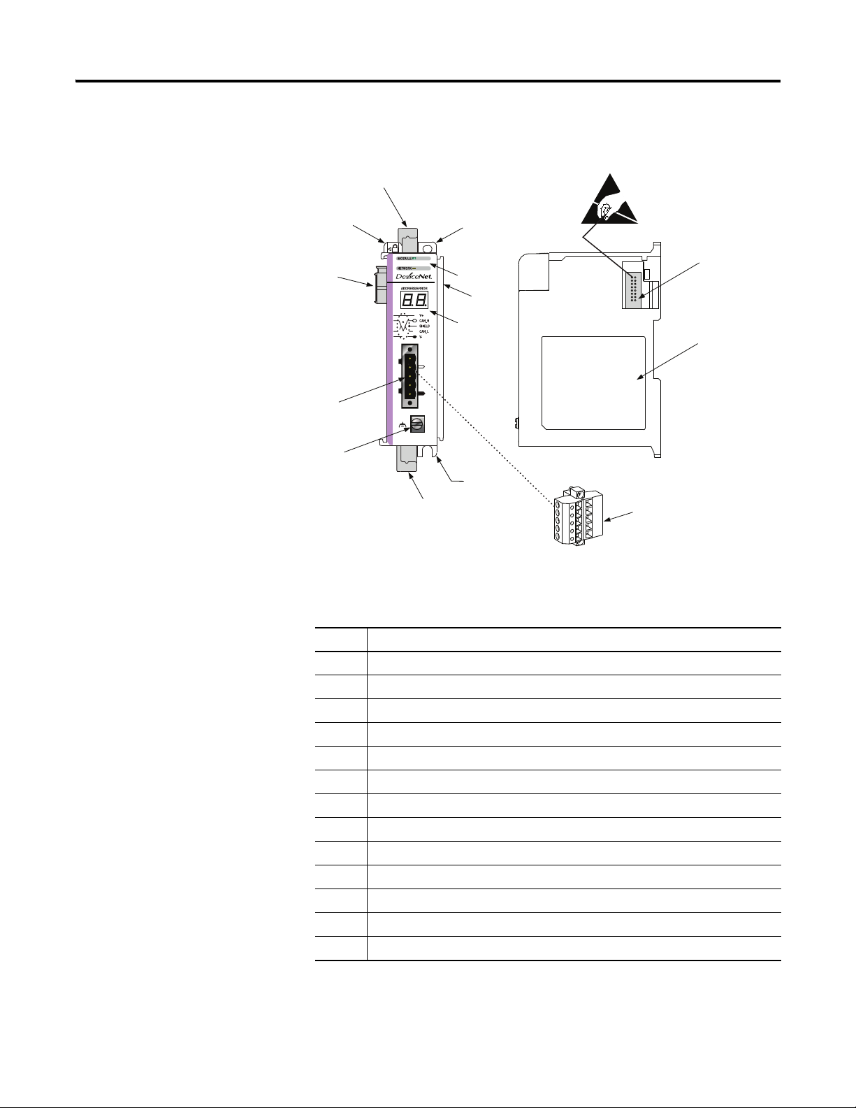
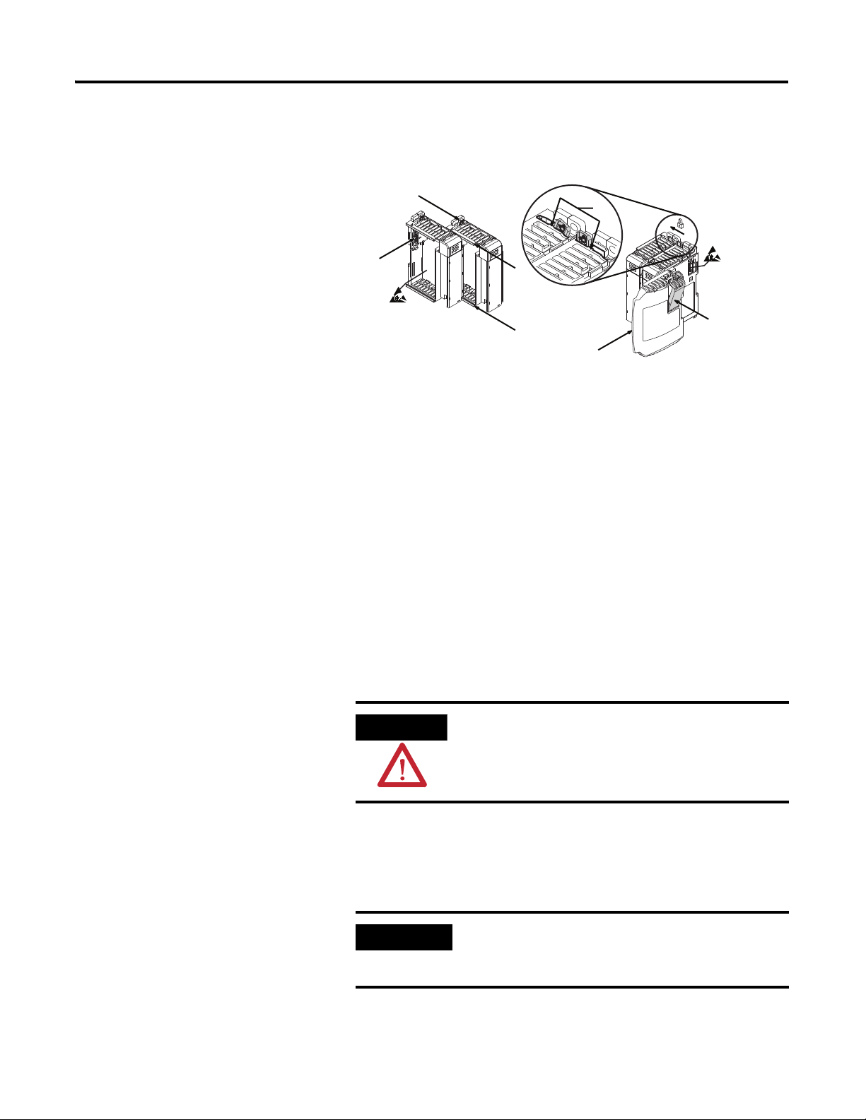
Module Features
Use the following figure to identify the features of the scanner.
2A
1
8A
7A
6
2B
3A
4
8B
5
3B
7B
8B
9
Module Features
Item Description
1 Bus lever (with locking function)
2A Upper DIN rail latch
2B Lower DIN rail latch
3A Upper panel mounting tab
3B Lower panel mounting tab
4 Module and Network status LEDs
5 Address and Error numeric display
6 Grounding screw
7A DeviceNet mating male receptacle
7B Removable DeviceNet female connector
8A Movable bus connector with female pins
8B Bus connector with male pins
9 Nameplate label
12 Publication 1769-UM009E-EN-P - August 2009
Page 13
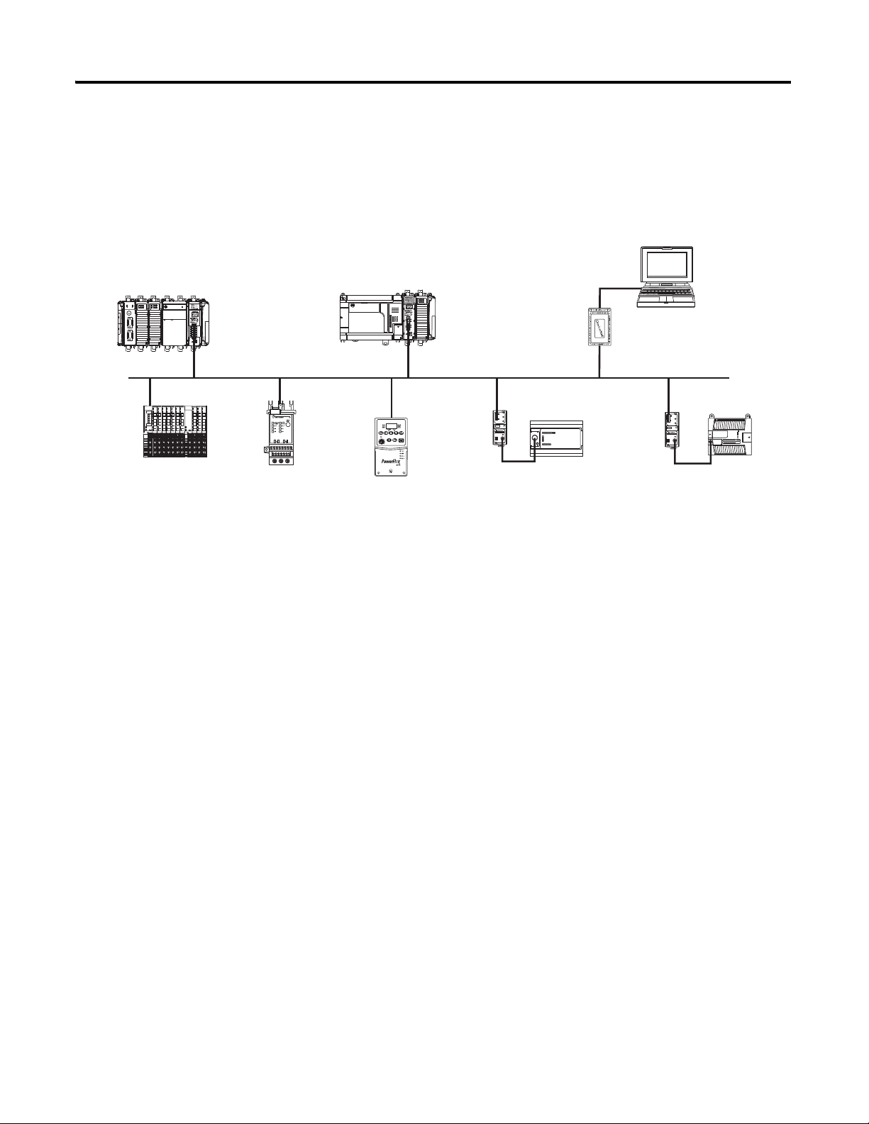
Overview Chapter 1
CompactLogix controller with
1769-SDN scanner
MicroLogix 1500 controller
with 1769-SDN scanner
PLC with RSNetWorx for
DeviceNet software
1784-PCD
Interface card
1734 POINT I/O E3 Overload
Relay
PowerFlex 40 Drive
Enhanced DeviceNet
Communications Module
MicroLogix 1000 Controller
with 1761-NET-DNI
MicroLogix 1200 Controller
with 1761-NET-DNI
Scanner Module Operation
In a typical configuration, the scanner module acts as an interface between
DeviceNet devices and the programmable controller.
Device Network
The scanner module communicates with DeviceNet devices over the network
to:
• Read inputs from slave devices
• Write outputs to slave devices
• Communicate with peer devices (messaging)
• Upload/download programs to a 1764-LRP based MicroLogix 1500
controller across a DeviceNet network
Publication 1769-UM009E-EN-P - August 2009 13
Page 14

Chapter 1 Overview
IMPORTANT
Communication with Your Slave Devices
The scanner module communicates with devices via strobe, poll, change of
state, or cyclic I/O messages. It uses these messages to solicit data from or
deliver data to each device. Data received from the devices, input data, is
organized by the scanner module and made available to the controller. Data
sent from your controller, output data, is organized in the scanner module and
sent on to your devices.
• A strobe message is a multicast transfer of data that is 64 bits in length
sent by the scanner module that initiates a response from each strobed
slave device.
The strobe devices respond with their data, which can be as much as 8
bytes of information. As a slave device, the scanner module does not
support the strobe message.
• A poll message is a point-to-point transfer of data from 0...128 bytes
sent by the scanner module to the slave device.
The poll message also initiates a response from each poll slave. The slave
device responds with its input data from 0...128 bytes.
• A change-of-state message is a transfer of data sent whenever a data
change occurs.
A user-configurable heartbeat rate allows devices to indicate proper
operation during intervals between data changes.
• A cyclic message is a transfer of data sent at a specific user-configurable
rate, such as every 50 ms.
Throughout this document, input and output are defined from
the controller’s point of view. Output is data sent from the
controller to a device. Input is data collected by the controller
from a device.
In addition to I/O messaging, the scanner module also supports PCCC and
CIP explicit messaging, defined later in this manual.
14 Publication 1769-UM009E-EN-P - August 2009
Page 15

Overview Chapter 1
1769-SDN Scanner Module Data Tables
The scanner module uses input and output data images to transfer data, status,
and command information between the scanner module and the MicroLogix
controller to manage the flow of data between your controller and network
devices.
Input Data Image - MicroLogix 1500
The input data image is transferred from the scanner module to the controller
across the Compact I/O bus.
Word Description Data Type
0…65 Status structure 66-word array
66…245 DeviceNet slave inputs 180-word array
See
Chapter 6
for definitions of the Status structure.
Output Data Image - MicroLogix 1500
The output data image is transferred from the controller to the scanner
module across the Compact I/O bus.
Word Description Data Type
0 and 1 Module command array 2-word array
2…181 DeviceNet slave outputs 180-word array
Publication 1769-UM009E-EN-P - August 2009 15
Page 16

Chapter 1 Overview
Module Command Array Bit Assignments
Output
Word
0 0 Run This bit controls when the module scans its
1 16…31
(1)
Bit Description Behavior
mapped slave devices. When set (1), the
scanner module will process I/O data as
defined by its scanlist. The Fault and Disable
Network command bits must be clear (0) to
scan the network.
1 Fault When set, the scanner’s I/O mode will be
Halt; messaging will still operate. The fault
bit is primarily used to artificially set the
slave devices into a fault state due to some
event or condition within the control
program.
2 Disable network When set, the scanner module is
functionally removed from the network.
3
4 Reset Restarts access to the DeviceNet network.
5…15
Do not manipulate reserved bits. Doing so may interfere with future compatibility.
Reserved
Reserved
Reserved
(1)
(1)
(1)
N/A
N/A
N/A
Input Data Image - CompactLogix
The input data image is transferred from the scanner module to the controller
across the Compact I/O bus.
Word Description Data Type
0…89 DeviceNet slave inputs 90-DINT array
Output Data Image - CompactLogix
The output data image is transferred from the controller to the scanner
module across the Compact I/O bus.
Word Description Data Type
0…89 DeviceNet slave outputs 90-DINT array
For additional information about the CompactLogix image structure, refer to
the DeviceNet Modules in Logix5000 Control Systems User Manual,
publication
DNET-UM004
.
16 Publication 1769-UM009E-EN-P - August 2009
Page 17

Overview Chapter 1
RSNetWorx for DeviceNet Software as a Configuration Tool
RSNetWorx for DeviceNet software is used to configure the scanner’s slave
devices. This software tool connects to the scanner module over the
DeviceNet network via an RS-232 interface (1770-KFD module) or PC card
(1784-PCD or 1784-PCID).
We recommend RSNetworx for DeviceNet software, version 3.00 or later.
If your RSNetWorx configuration software does not include the required
electronic data sheet (EDS) file, go to
Register the new EDS file by using the EDS wizard in RSNetWorx for
DeviceNet software. Access the wizard from the Tools menu. This
configuration tool lets you to identify all of the DeviceNet devices and their
locations in your system.
The controller must be in Program mode, or the scanner module in Idle mode
(bit 0 of the Module Command Array = 0) for the scanner module to accept
the configuration information.
http://www.ab.com/networks/eds
.
Publication 1769-UM009E-EN-P - August 2009 17
Page 18
Chapter 1 Overview
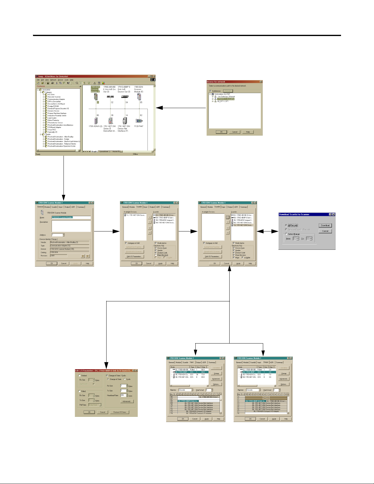
The main RSNetWorx dialog.
Click the Input tab and click
the AutoMap button to
automatically map input
devices.
Click the Output tab and click
the AutoMap button to
automatically map output
devices.
Click Online and select the
driver to browse the network.
Double-click the 1769-SDN icon to access
the 1769-SDN scanner module.
Click on the Scanlist tab to
access the scanlist.
Move the device into
the scanlist.
Click Download to Scanner to
download the scanlist.
Double-click the device in the
scanlist to edit a device’s I/O
parameters.
RSNetWorx Configuration Dialog Map
18 Publication 1769-UM009E-EN-P - August 2009
Page 19

Quick Start for Experienced Users
Chapter
2
Introduction
Required Tools and Equipment
This chapter helps you get started using the 1769-SDN scanner module.
Topic Page
Required Tools and Equipment 19
What You Need to Do 20
Procedures are based on the assumption that you have an understanding of
Rockwell Automation controllers. You should understand electronic process
control and be able to interpret the ladder logic instructions required to
generate the electronic signals that control your application. Because it is a
start-up guide for experienced users, this chapter does not contain detailed
explanations about the procedures listed.
Have the following tools and equipment ready:
• Personal computer
• Programmable controller: CompactLogix or MicroLogix 1500 system
• 1770-KFD RS-232 DeviceNet adapter or 1784-PCIDS, 1784-U2DN
DeviceNet interface card
• For network communication: RSLinx software, version 2.30 or later
• For DeviceNet network configuration:
– RSNetWorx for DeviceNet software, version 3.00 or later
• For ladder logic programming:
– RSLogix 500 programming software, version 5.00.10 or later, or
– RSLogix 5000 programming software, version 8.02 or later
• 1769-SDN scanner module
• Mounting hardware
• Screwdriver
19Publication 1769-UM009E-EN-P - August 2009 19
Page 20
Chapter 2 Quick Start for Experienced Users
ATTENTION
What You Need to Do
Follow these steps to get started using the 1769-SDN scanner module.
1. Verify planned system configuration.
a. Ensure system power supply has sufficient current.
Maximum Current Draw
Module 5V DC 24V DC
1769-SDN 440 mA 0 mA
The scanner module cannot be located more than four modules away
from the system power supply.
b. Verify that the DeviceNet network has adequate power.
DeviceNet Power Requirements
Module DeviceNet Power Requirements
1769-SDN N.E.C. Class 2
90 mA @ 11V DC, max.
110 mA @ 25V DC, max.
2. Remove power.
200 mA for 1.5 ms inrush
Remove power before removing or inserting this module. When
you remove or insert a module with power applied, an electrical
arc may occur. An electrical arc can cause personal injury or
property damage by:
• sending an erroneous signal to your system’s field devices,
causing unintended machine motion.
• causing an explosion in a hazardous environment.
Electrical arcing causes excessive wear to contacts on both the
module and its mating connector and can lead to premature
failure.
20 Publication 1769-UM009E-EN-P - August 2009
Page 21

Quick Start for Experienced Users Chapter 2
3. Assemble and mount the I/O bank.
The scanner module can be attached to an adjacent controller, power
supply, or I/O module. The scanner module can be panel or DIN-rail
mounted. Modules can be assembled before or after mounting.
Be sure to observe minimum spacing guidelines for adequate
ventilation.
4. Ground the scanner module and complete the DeviceNet network
wiring.
5. Apply power to the system.
6. Be sure that the programming software and equipment is ready.
7. Use RSLinx to configure drivers.
8. Use RSNetWorx for DeviceNet software to configure the 1769-SDN
scanner module and the DeviceNet devices.
9. Use RSLogix software to create your project and ladder logic.
10. Start the system.
a. Apply power.
b. Download your program and put the controller into Run mode.
c. status indicators turn on solid green.
11. Monitor the scanner module status to check if the scanner module is
operating correctly.
Module status is reported by the status indicators and numeric display
on the front of the scanner module. The information is also stored in
the scanner module’s input data file, so these bits can be used in your
control program to flag an error.
Publication 1769-UM009E-EN-P - August 2009 21
Page 22

Chapter 2 Quick Start for Experienced Users
Notes:
22 Publication 1769-UM009E-EN-P - August 2009
Page 23

Chapter
3
Installation and Wiring
This chapter describes how to install and wire the 1769-SDN scanner module.
This table describes what this chapter contains and where to find specific
information.
Topic Page
Power Requirements 23
General Considerations 24
System Planning 26
System Assembly 27
System Mounting 28
Replace the Scanner Module within a
System
31
Power Requirements
Field Wiring Connections 32
Scanner Module Power-up 33
The scanner module receives power through the Compact I/O bus interface
from the +5V DC system power supply.
Maximum Current Draw
Module 5V DC 24V DC
1769-SDN 440 mA 0 mA
The scanner module also draws power from the DeviceNet network.
DeviceNet Power Requirements
Module DeviceNet Power Requirements
1769-SDN N.E.C. Class 2
90 mA @ 11V DC, max.
110 mA @ 25V DC, max.
200 mA for 1.5 ms, inrush
23Publication 1769-UM009E-EN-P - August 2009 23
Page 24
Chapter 3 Installation and Wiring
WARNING
General Considerations
The Compact I/O system is suitable for use in an industrial environment
when installed in accordance with these instructions. Specifically, this
equipment is intended for use in clean, dry environments (Pollution Degree
(1)
) and to circuits not exceeding Over Voltage Category II
2
60664-1).
(3)
(2)
(IEC
Hazardous Location Considerations
This equipment is suitable for use in Class I, Division 2, Groups A, B, C, D or
nonhazardous locations only. The following WARNING statement applies to
use in hazardous locations.
EXPLOSION HAZARD
Substitution of components may impair suitability for Class I,
Division 2.
Do not replace components or disconnect equipment unless
power has been switched off or the area is known to be
nonhazardous.
Do not connect or disconnect components unless power has
been switched off or the area is known to be nonhazardous.
This product must be installed in an enclosure.
All wiring must comply with N.E.C. article 501-4(b).
(1)
Pollution Degree 2 is an environment where, normally, only nonconductive pollution occurs except that
occasionally a temporary conductivity caused by condensation shall be expected.
(2)
Over Voltage Category II is the load level section of the electrical distribution system. At this level, transient
voltages are controlled and do not exceed the impulse voltage capability of the product’s insulation.
(3)
Pollution Degree 2 and Over Voltage Category II are International Electrotechnical Commission (IEC)
designations.
24 Publication 1769-UM009E-EN-P - August 2009
Page 25
Preventing Electrostatic Discharge
ATTENTION
ATTENTION
Electrostatic discharge (ESD) can damage integrated circuits or
semiconductors if you touch the bus connector pins. Follow these
guidelines when you handle the module:
• Touch a grounded object to discharge static potential.
• Wear an approved wrist-strap grounding device.
• Do not touch the bus connector or connector pins.
• Do not touch circuit components inside the module.
• Use a static-safe work station, if available.
• Keep the module in its static-shield box when it is not in use.
Installation and Wiring Chapter 3
Removing Power
Remove power before removing or inserting this module. When you
remove or insert a module with power applied, an electrical arc may
occur. An electrical arc can cause personal injury or property damage
by:
• sending an erroneous signal to your system’s field devices,
causing unintended machine motion.
• causing an explosion in a hazardous environment.
Electrical arcing causes excessive wear to contacts on both the
module and its mating connector and can lead to premature failure.
Reducing Noise
We recommend installing this module in an industrial enclosure to reduce the
effects of electrical interference. Group your modules to minimize adverse
effects from radiated electrical noise and heat.
Publication 1769-UM009E-EN-P - August 2009 25
Page 26

Chapter 3 Installation and Wiring
Protecting the Circuit Board from Contamination
The printed circuit boards of the modules must be protected from dirt, oil,
moisture, and other airborne contaminants. We recommend installing the
system in an enclosure suitable for the environment to protect these boards.
The interior of the enclosure should be kept clean and the enclosure door
should be kept closed whenever possible.
System Planning
Consider the following when planning your system:
• The scanner module can communicate with up to 63 DeviceNet devices.
• The scanner, as a master, can own up to 63 slave I/O nodes.
• The scanner module can simultaneously be a master and a slave owned
by another DeviceNet master.
• A 1769-ECR right end cap or 1769-ECL left end cap is required to
terminate the end of the Compact I/O bus.
• Each bank of Compact I/O modules must have its own power supply.
A MicroLogix 1500 controller acts as the power supply for modules
directly connected to it.
• A Compact I/O power supply, or MicroLogix 1500 base unit, has limits
on the amount of +5V DC and +24V DC current it can supply to
modules in its I/O bank.
These limits depend on the catalog number of the power supply, for
example, 1769-PA2. A bank of modules must not exceed the current
limits of the I/O bank power supply or MicroLogix 1500 base unit.
Refer to the Compact 1769 Expansion I/O Power Supplies Installation
Instructions, publication
Manual, publication
1764-UM001
1769-IN028
, or the MicroLogix 1500 User
.
• The scanner module has a distance rating of four, therefore, the scanner
module must be within four modules of the I/O bank’s power supply.
• Determine the DeviceNet communication rate, based on standard
DeviceNet considerations.
• Consider the number of words of I/O data the host controller supports.
For more information on planning your DeviceNet network, refer to the
DeviceNet Media Design Installation Guide, publication
26 Publication 1769-UM009E-EN-P - August 2009
DNET-UM072
.
Page 27
Installation and Wiring Chapter 3
ATTENTION
IMPORTANT
G
F
E
D
B
A
B
C
System Assembly
The scanner module can be attached to an adjacent controller, power supply,
or I/O module. This procedure shows you how to assemble the Compact I/O
system.
1. Disconnect power.
2. Check that the bus lever of the scanner module (A) is in the unlocked
(fully right) position.
3. Use the upper and lower tongue-and-groove slots (B) to secure the
modules together.
4. Move the scanner module back along the tongue-and-groove slots until
the bus connectors (C) line up with each other.
5. Use your fingers or a small screwdriver to push the bus lever back
slightly to clear the positioning tab (D).
6. Move the scanner module’s bus lever fully to the left (E) until it clicks.
Make sure it is locked firmly in place.
When attaching I/O modules, it is very important that the
bus connectors are securely locked together for a proper
electrical connection.
7. Attach an end cap terminator (F) to the last module in the system by
using the tongue-and-groove slots as before.
8. Lock the end cap bus terminator (G).
A 1769-ECR or 1769-ECL right or left end cap must be
used to terminate the end of the serial communication
bus.
Publication 1769-UM009E-EN-P - August 2009 27
Page 28
Chapter 3 Installation and Wiring
ATTENTION
Host Controller
Compact I/O
Compact I/O
Compact I/O
Compact I/O
Compact I/O
End Cap
Side Side
Top
Bottom
System Mounting
During panel or DIN rail mounting of all devices, be sure that all
debris (metal chips, wire strands) is prevented from falling into
the module. Debris that falls into the module could cause
damage at power up.
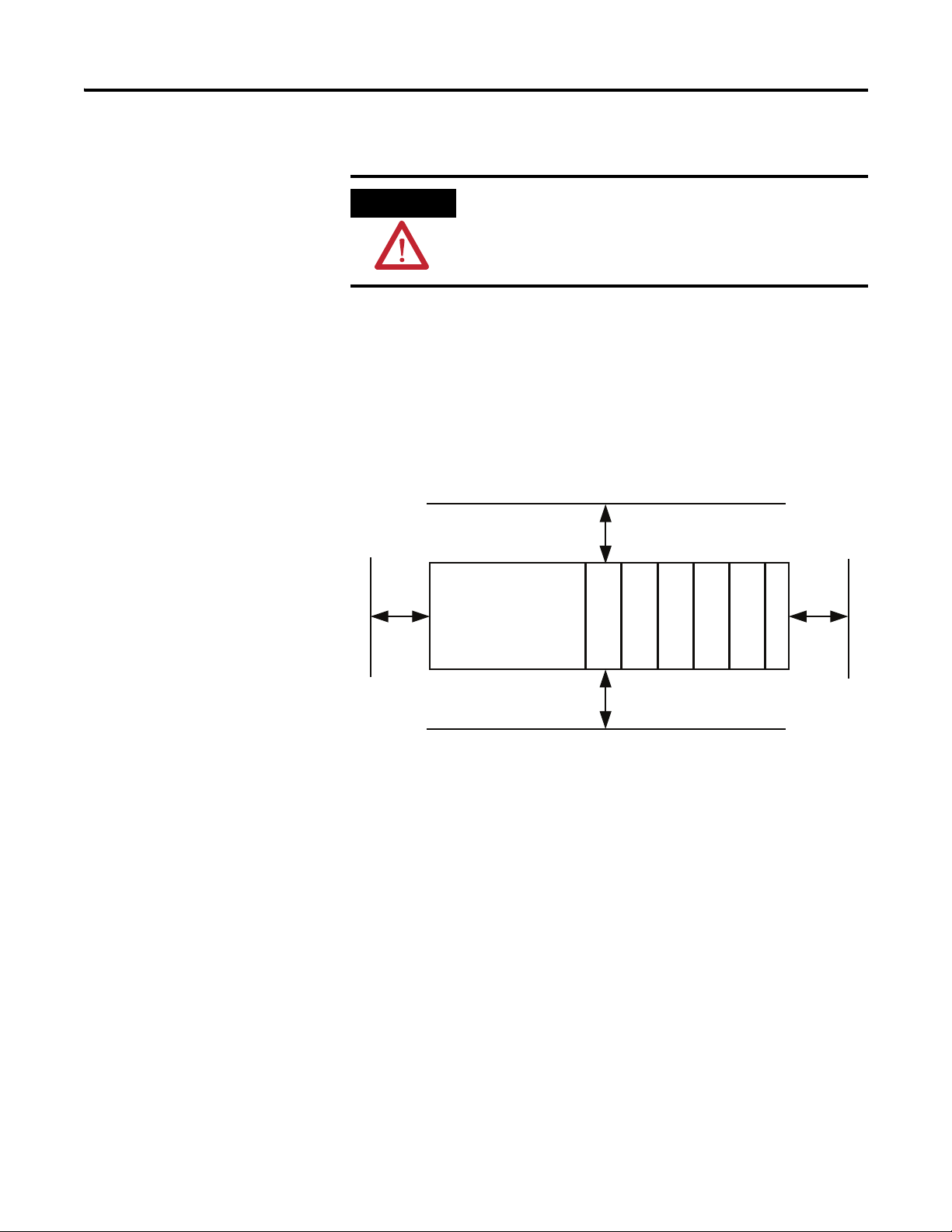
Minimum Spacing
Maintain spacing from enclosure walls, wireways, and adjacent equipment.
Allow 50 mm (2 in.) of space on all sides for adequate ventilation, as shown
below.
Allow at least 110 mm (4.33 in.) of enclosure depth to accommodate the
scanner module and the DeviceNet connector.
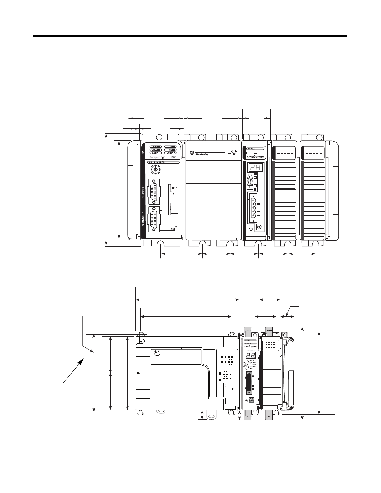
Panel Mounting
Mount the scanner module to a panel, using two screws per scanner module.
Use M4 or #8 panhead screws. Mounting screws are required on every
module.
28 Publication 1769-UM009E-EN-P - August 2009
Page 29
Installation and Wiring Chapter 3
15 mm
(0.59 in)
67.5 mm
(2.68 in)
52.5 mm
(2.06 in)
132 mm
(5.20 in)
70.0 mm
(2.76 in)
35.0 mm
(1.38 in)
118 mm
(4.65 in)
35.0 mm
(1.38 in)
35.0 mm
(1.38 in)
35.0 mm
(1.38 in)
35.0 mm
(1.38 in)
52.5 mm
(2.07 in)
DIN Rail
Center Line
Mounting Hole
Dimension
168 mm (6.62 in)
147 mm (5.79 in)
35 mm
(1.38 in.)
35 mm
(1.38 in.)
28.5 mm
(1.12 in.)
13.5 mm
(0.53 in.)
14.7 mm
(0.58 in.)
147.4 mm (5.8 in.)
132 mm (5.19 in.)
118 mm (4.65 in.)
59 mm
(2.32 in.)
59 mm
(2.32 in.)
122.6 mm (4.83 in.)
Panel Mounting Using the Dimensional Drawing
All dimensions are in millimeters (inches). Hole spacing tolerance: ±0.4 mm
(0.016 in.).
Compact I/O System with L35E CompactLogix Controller and Power Supply
Compact I/O System with MicroLogix 1500 Base Unit and Processor
Publication 1769-UM009E-EN-P - August 2009 29
Page 30
Chapter 3 Installation and Wiring
Dimension Height
A 118 mm (4.65 in.)
B 59 mm (2.325 in.)
Panel Mounting Procedure Using Modules as a Template
This procedure lets you use the assembled modules as a template for drilling
holes in the panel. Due to module mounting hole tolerance, it is important to
follow these procedures.
1. On a clean work surface, assemble no more than three modules.
2. Using the assembled modules as a template, carefully mark the center of
all module-mounting holes on the panel.
3. Return the assembled modules to the clean work surface, including any
previously mounted modules.
4. Drill and tap the mounting holes for the recommended M4 or #8 screw.
5. Place the modules back on the panel, and check for proper hole
alignment.
6. Attach the modules to the panel using the mounting screws.
If mounting more modules, mount only the last one of this group and
put the others aside. This reduces remounting time during drilling and
tapping of the next group.
7. Repeat steps 1...6 for any remaining modules.
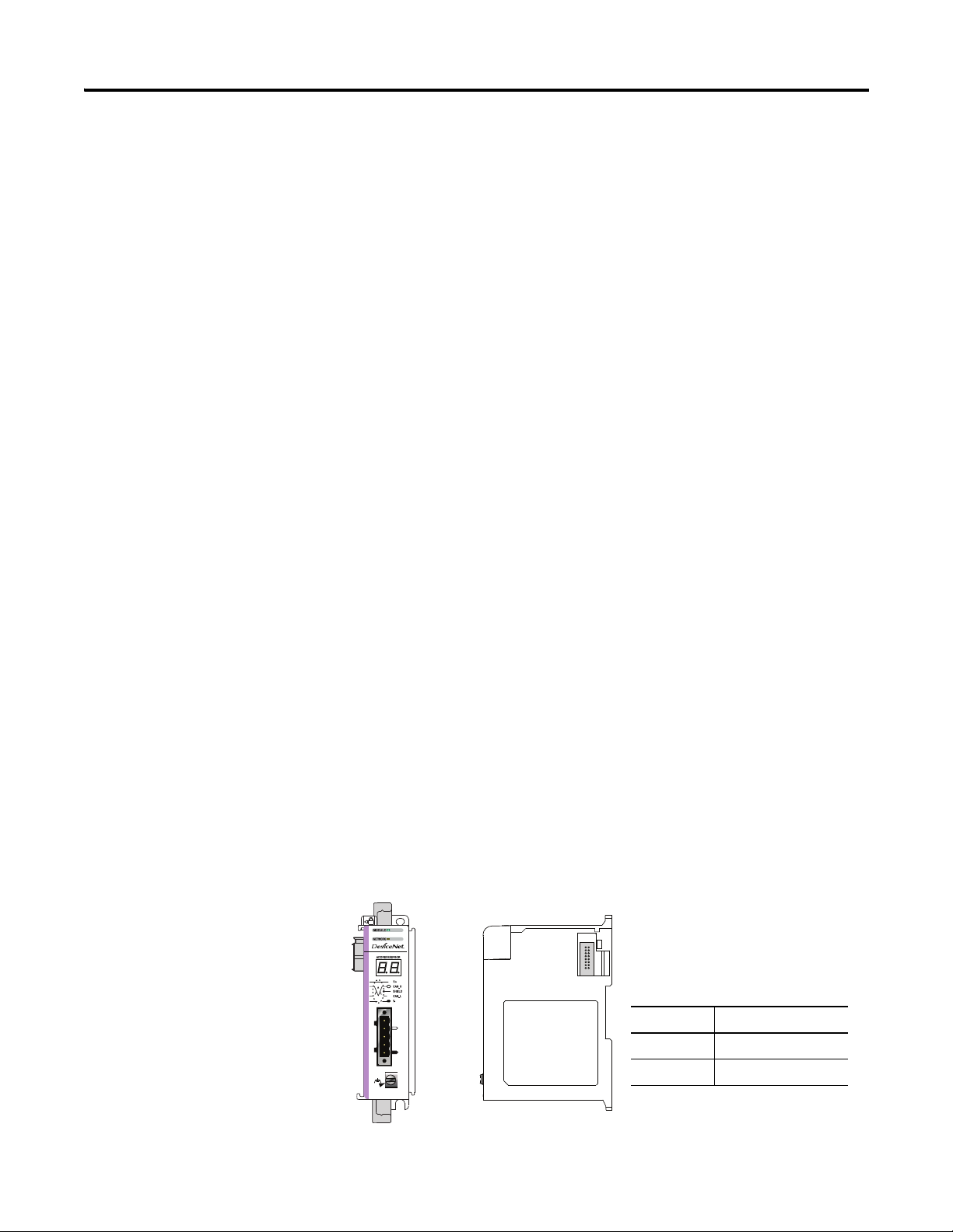
DIN Rail Mounting
The module can be mounted using the following DIN rails:
• 35 x 7.5 mm (EN 50022 - 35 x 7.5) or 35 x 15 mm (EN 50022 - 35 x 15).
Before mounting the module on a DIN rail, close the DIN rail latches. Press
the DIN rail mounting area of the module against the DIN rail. The latches
will momentarily open and lock into place. DIN rail mounting dimensions are
shown below.
DIN rail mounting dimensions
30 Publication 1769-UM009E-EN-P - August 2009
Page 31

Installation and Wiring Chapter 3
IMPORTANT
Replace the Scanner Module within a System
The scanner module can be replaced while the system is mounted to a panel
(or DIN rail) once power is removed.
1. Remove power.
2. Remove the DeviceNet cable from the scanner module by removing the
DeviceNet connector.
3. Remove the upper and lower mounting screws from the scanner module
(or open the DIN rail latches using a flat-blade screwdriver).
4. On the scanner module to be replaced and the right-side adjacent
module (or end cap if the scanner module is the last module in the
bank), move the bus levers to the right (unlock) to disconnect the
scanner module from the adjacent modules.
5. Gently slide the disconnected scanner module forward.
6. If you feel excessive resistance, make sure that you disconnected the
scanner module from the bus and that you removed both mounting
screws (or opened the DIN latches).
It may be necessary to rock the scanner module slightly from front to
back to remove it, or, in a panel-mounted system, to loosen the screws
of adjacent modules.
7. Before installing the replacement scanner, be sure that the bus lever on
the right-side adjacent module is in the unlocked (fully right) position.
8. Slide the replacement scanner module into the open slot.
9. Connect the scanner module and modules together by locking (fully left)
the bus levers on the replacement scanner module and the right-side
adjacent module or end cap.
10. Replace the mounting screws (or snap the scanner module onto the
DIN rail).
11. Replace the DeviceNet cable on the scanner module by attaching the
connector to the scanner.
12. Restore the scanner module configuration using RSNetWorx for
DeviceNet software.
Be sure that the new module has the same node address
and communication rate as the module that was
replaced.
Publication 1769-UM009E-EN-P - August 2009 31
Page 32

Chapter 3 Installation and Wiring
ATTENTION
DeviceNet
Connector
Connect
(1)
(1)
DeviceNet cable colors are shown on the
wiring label on the front of the scanner
To
Red Wire V+
White Wire CAN High
Bare Wire Shield
Blue Wire CAN Low
Black Wire V-
Grounding Screw
Use 2.1 mm
2
(14 AWG
wire to connect to
panel ground.
Field Wiring Connections
Follow these procedures to wire the scanner module.
Grounding the Scanner Module
This product is intended to be mounted to a well-grounded mounting surface,
such as a metal panel. Additional grounding connections from the scanner’s
mounting tabs or DIN rail (if used), are not required unless the mounting
surface cannot be grounded.
The grounding screw on the front of the scanner module must
be connected to a suitable ground source when operating in
2
electrically noisy environments. Use a 2.1 mm
to make this connection.
For additional information on grounding the scanner module, refer to
Industrial Automation Wiring and Grounding Guidelines, Allen-Bradley
publication
DeviceNet Wiring
1770-4.1
.
(14 AWG) wire
32 Publication 1769-UM009E-EN-P - August 2009
Page 33

Installation and Wiring Chapter 3
IMPORTANT
1. Connect the DeviceNet cable to the removable connector as shown.
2. Insert the removable female connector into the mating male connector
on the DeviceNet scanner module.
3. Screw the removable connector to the scanner module case with the
upper and lower mounting screws to a torque of 0.6...0.7 Nm (5...6
in-lbs).
If the 1769-SDN scanner module is the first or last device
connected to the DeviceNet network trunkline, be sure to add a
termination resistor (120 Ω 1% ≥ ¼W resistor, Allen-Bradley
part number 1485A-C2) across the Blue (CAN Low) and White
(CAN High) wires.
Scanner Module Power-up
When power is applied via the Compact I/O bus, the scanner module goes
through a self test sequence. Upon successful completion of the self test, the
scanner module is ready to communicate.
The default scanner module settings are:
• Communication rate = 125 Kbps
• Node address = 63
Use your configuration software to change the communication rate and node
address.
Publication 1769-UM009E-EN-P - August 2009 33
Page 34

Chapter 3 Installation and Wiring
Notes:
34 Publication 1769-UM009E-EN-P - August 2009
Page 35

Automatically Configure a
DeviceNet Network
Chapter
4
Introduction
This chapter provides a quick method for configuring a DeviceNet network. It
uses the AutoScan feature to establish communication between the controller
and your devices with minimal steps.
Topic Page
Determine If You Can Use AutoScan 38
Review How AutoScan Effects Your Network 38
Connect Each Device to the Network 39
Add the Scanner to the RSLogix 5000 Project 44
Implement AutoScan 46
Additional Considerations Regarding AutoScan 53
Access Device Data 57
Put the Scanner in Run Mode 60
The DeviceNet AutoScan feature enables a scanner to automatically map a
network of slave devices into its scanlist without the use of RSNetWorx for
DeviceNet software. This greatly improves the ease of setting up a DeviceNet
network, especially networks comprised of simple devices.
When the feature is enabled, a DeviceNet scanner continuously searches for
devices on the network. Once a qualifying slave device is found, it is added to
the scanner's scanlist and its I/O data is mapped into a predefined location in
the scanner's I/O memory table based on the device's node address.
35Publication 1769-UM009E-EN-P - August 2009 35
Page 36

Chapter 4 Automatically Configure a DeviceNet Network
EXAMPLE
How AutoScan Operates
AutoScan is active when the feature is enabled and the scanner is in IDLE
mode. When active, the scanner attempts to connect to each device not
enabled in the scan list. The scanner only checks for devices with node
addresses between 0 and 61, inclusive. The connections to these devices are
made on a round robin basis.
When a device is found, the scanner gets the Produced and Consumed data
sizes from the slave devices's Connection Object instance(s).
• If the Produced data size is greater than the configured I/O allocation
size, the device is added to the scanlist with a produced size set equal to
the I/O allocation size.
When this happens, an I/O connection is made with the device. But it
errors and error code #77 is displayed on the 1769-SDN for the device’s
node number.
• If the Consumed data size is greater than the configured I/O allocation
size, then the node is rejected and not entered into the scan list.
However, you can change the I/O allocation size, as described in
Allocation Size Via the User Program
Produced and Consumed data sizes in your scanlist.
, to accommodate the device with the largest
Configure I/O
For qualifying nodes, the scanner enters the device into the scan list and
attempts to allocate an I/O connection using one of the following
communication format choices, in this particular order:
• Change Of State (COS) EPR = 250ms
• Poll EPR = 75ms
• Strobe EPR = 75ms
• Cyclic EPR = 500ms
If a photoeye was connected on a network that only supported
strobed connections, the scanner does a couple of things.
• First, the scanner recognizes that a device exists for which
memory was available for the node number with the
configured allocation size on a network that was not
currently mapped.
• Then, the scanner would attempt to initiate both COS and
polled connections first, but the strobed connection would
be selected as that is the only connection that the photoeye
supported.
36 Publication 1769-UM009E-EN-P - August 2009
Page 37

Automatically Configure a DeviceNet Network Chapter 4
EXAMPLE
01 02 03 05
IMPORTANT
The input and output data is mapped into the scanner's I/O data table based
on the device's node address and the configured fixed mapping size. The
DINT-based formula is used with the CompactLogix controller for calculating
the Input or Output data location is:
Input (Output) Offset = [(Node Address) x (Allocation Size)] / 4
When using the default fixed mapping size of 4 bytes, the input data for the devices shown in the example
below is allocated in the 1769-SDN's input table as shown below. Notice node 1 is located in the data map
at DINT location 1, node 2 at DINT location 2, and so on.
Notice that, in this example, node 4 is unused. However, the I/O memory slot remains allocated for it.
If you are using a MicroLogix 1500 controller with a 1769-SDN
scanner, you must use the following WORD-based formula for
calculating the Input or Output data location:
Input (Output) Offset = ([(Node Address) x (Allocation Size)] / 2) +
Data Offset
In this formula the Data Offset = 66 for Input Offset and 2 for
Output Offset.
The data offset value is used to account for scanners that have a fixed status
field at the start of the input or output data, for example, the 1769-SDN
scanner.
Publication 1769-UM009E-EN-P - August 2009 37
Page 38

Chapter 4 Automatically Configure a DeviceNet Network
DINT Input Memory
0
device at address 0
1
device at address 1
2
device at address 2
The actual data for the device
fills the portion that it needs
and the rest remains unused.
DINT Input Memory
0
device at address 0
1
2
device at address 1
3
4
device at address 2
5
The actual data for the
device fills the portion
that it needs and the rest
remains unused.
For example, if you specify 2
DINTs (8 bytes) per address,
the scanner sets aside 2
DINTs for each address.
Determine If You Can Use AutoScan
How AutoScan Effects
Make sure your network meets the following requirements to use this chapter:
• The scanner’s I/O allocation size is configured to accommodate the
input and output data sizes of all devices on your DeviceNet network.
The default AutoScan setting allocates a 4-byte entry in both the input
and output memory maps in the scanner for each slave device detected
on the network. This default size is chosen to accommodate the default
Logix native data size of 32 bits, that is a DINT.
If you use a device that sends more than 4 bytes of input or output data,
for example, an E3 Solid State Overload Relay (catalog number
193-ECxx), you must change the I/O allocation size.
• You are using the CompactLogix 1769-SDN DeviceNet scanner with
firmware revision 4.1 or greater.
If your network does not meet the requirements listed above, then use
5
and
Chapter 7
to configure your network and control your devices.
Chapter
As you use AutoScan, keep the following in mind:
Your Network
Consideration Description
AutoScan clears the current
configuration.
AutoScan allocates a fixed
memory size for each device.
The bytes/node value defines
how much memory for each
address.
38 Publication 1769-UM009E-EN-P - August 2009
With AutoScan, the scanner automatically sets up communication with the devices on your DeviceNet
network. When you turn on the AutoScan option, the scanner removes any previous configuration that
was done to the scanner.
At its default setting, AutoScan allocates 1 DINT of input memory and 1 DINT of output memory for
each device on the DeviceNet network.
AutoScan lets you specify how much input and output memory to give to each address on your network.
Page 39

Consideration Description
Automatically Configure a DeviceNet Network Chapter 4
New devices are automatically
available.
The Automatic Device Recovery
(ADR) option is not available.
While the scanner is in idle mode, AutoScan continues to establish communication with devices that
you connect to the network, as long as the device uses input data and output data sizes that fit in the
scanner’s I/O allocation size.
You have to use RSNetWorx for DeviceNet software to edit the configuration of the scanner to use the
Automatic Device Recovery (ADR) option of a DeviceNet scanner. This turns off AutoScan.
Connect Each Device to the Network
As you connect your devices to the DeviceNet network, follow these
guidelines:
1. Assign an address to each device. The following addresses are
recommended but not required.
Give this address To this device
0 scanner
1…61 your devices
62 hand held configurator, such as the DeviceNet Configuration
Terminal, catalog number 193-DNCT
63 Leave open. Out of the box, a DeviceNet device is preset for
address 63. Leaving address 63 open lets you get a new device on
the network without conflicting with another device.
2. Connect the scanner and any network interface to the network.
By first connecting the scanner and/or network interface device to the
network, you reduce the number of baud rate errors as you connect the
rest of your devices:
• Scanners and network interface devices use a fixed baud rate.
• Sensors and similar DeviceNet devices use autobaud to set their baud
rate. They wait for another device to communicate. Then they set
their baud rate to the same baud rate as the other device.
• By first placing a scanner or network interface on the network, the
other devices have a baud rate against which to set their baud rate.
• Initially, leave the baud rate of the scanner and network interface at
the default setting of 125K bits/s. If you want to change the baud
rate, wait until after you establish communication with all your
devices at the default setting (125K).
Set the Node Address of a Device Via a DeviceNet
•See
Configuration Terminal
on
page 42
to set the scanner’s DeviceNet
address.
Publication 1769-UM009E-EN-P - August 2009 39
Page 40

Chapter 4 Automatically Configure a DeviceNet Network
Actual Terminal
Node Address
Address = Fixed HMI MacID
Auto = Auto Addressing
Actual Baud Rate
baud = Fixed Baud Rate
Auto = Autobaud
3. Connect the rest of your devices to the network one at a time.
• Out of the box, a DeviceNet device is preset for address 63. Connect
and set the devices one at a time to set the scanner’s DeviceNet
address. Otherwise the address conflicts may prevent communication
with them.
• If a device has a switch to set its baud rate, set the switch to
autobaud, if available. Otherwise, set the device to the baud rate of
the network.
• After you change the address or baud rate of a device via a switch,
cycle power to the device.
• If a device has no switch or pushbutton for its address or baud rate,
Set the Baud Rate of a Device Via a DeviceNet Configuration Terminal
see
below.
• After you set the address of a device, check its network status
indicator. Typically, a solid red indicator means an address conflict or
problem with the baud rate.
Set the Baud Rate of a Device Via a DeviceNet
Configuration Terminal
Follow these steps to set the baud rate for your DeviceNet network via the
DeviceNet Configuration Terminal, catalog number 193-DNCT. For the rest
of the chapter, the terminal is referred to as the 193-DNCT terminal.
1. Connect the 193-DNCT terminal to the network. The following display
appears for 10 seconds which shows the unit setup and the baud rate
and node number values it has determined.
40 Publication 1769-UM009E-EN-P - August 2009
Page 41

Automatically Configure a DeviceNet Network Chapter 4
IMPORTANT
The 193-DNCT terminal is shipped so that when it is placed on
a DeviceNet network for the first time, it automatically sets its
baud rate to that of the traffic on the network. The terminal
uses Auto Addressing to assign itself an unused network node
address.
After 10 seconds a Network Who screen similar to the example
shown below should appear that displays all Nodes and associated
devices on the network.
If the Network Who screen does not appear as expected, then the
193-DNCT terminal may be set to autobaud enabled and is not able
to determine a communication rate because no communication is
occurring on the network at this time.
Follow these steps to disable the autobaud feature and set the baud rate.
1. On the 193-DNCT terminal keypad, press <ESC> .
2. Select the AutoBaud option and use <Up Arrow> to
select Disable.
3. Press <SEL> to advance to the BaudRate option.
4. With the BaudRate option selected, use <Up Arrow> to select
the appropriate baud rate.
5. Press <Enter> to complete the node commissioning function.
6. Press <ESC> to exit setup.
Publication 1769-UM009E-EN-P - August 2009 41
Page 42

Chapter 4 Automatically Configure a DeviceNet Network
Actual Terminal
Node Address
Address = Fixed HMI MacID
Auto = Auto Addressing
Actual Baud Rate
baud = Fixed Baud Rate
Auto = Autobaud
Set the Node Address of a Device Via a DeviceNet
Configuration Terminal
Follow these steps to set the node address of a device on your DeviceNet
network via the 193-DNCT terminal.
1. Connect the 193-DNCT terminal to the network. The following display
should appear for 10 seconds that shows the unit setup and the baud
rate and node number values it has determined.
After 10 seconds a Network Who screen similar to the example shown
below should appear that displays all Nodes and associated devices on
the network.
2. Use <Down Arrow> on the 193-DNCT terminal to scroll down
through the list until the last entry for node 63 is highlighted, which
should read 63 - No Product Name.
3. Press <Enter> to advance to the configuration screen.
4. Use <Down Arrow> to select the Tools option.
42 Publication 1769-UM009E-EN-P - August 2009
Page 43

Automatically Configure a DeviceNet Network Chapter 4
5. Press <Enter> and a screen appears with the NodeComm
option highlighted.
6. Press <Enter> and the Node Commissioning screen appears as
shown below with the BaudRate option highlighted.
7. Because you do not need to change the baud rate, press <SEL> to
advance to the Address option and highlight it.
8. Press the numbers on the key pad for the node number that you plan to
use for the device that was just installed on the DeviceNet network and
press <Enter> .
When the address is changed an Apply Changes messages appears on
the screen.
9. Press <SEL> to highlight the Apply Changes message.
10. Press <Enter> to complete the node commissioning function.
After approximately two seconds, the 193-DNCT terminal re-initializes
and in another 10 seconds, the 193-DNCT terminal again displays the
Network Who screen. At this point, the new node appears in the table.
Publication 1769-UM009E-EN-P - August 2009 43
Page 44

Chapter 4 Automatically Configure a DeviceNet Network
2
3
Add the Scanner to the RSLogix 5000 Project
Add the scanner to the I/O configuration of the controller to access the data
of your network.
Add the Scanner to the I/O Configuration Folder
1. Right-click and choose New Module.
2. Choose the type of scanner.
3. Click OK.
44 Publication 1769-UM009E-EN-P - August 2009
Page 45

Automatically Configure a DeviceNet Network Chapter 4
4
5
1
2
3
4
5
4. Select the Major revision of the scanner.
5. Click OK.
Define the Properties of the Scanner
1. Name the scanner.
2. Set the scanner Minor Revision.
3. Choose the size of the input and output memory maps that the scanner
will allocate for each device it detects on the network. Valid values range
from 0 to 32 bytes per node.
4. If you need to make additional configuration changes, such as setting the
Requested Packet Interval (RPI), leave the Open Module Properties box
checked.
5. Click OK
6. When the Module Properties dialog appears, that is, if you left the Open
Module Properties box checked, make additional required configuration
changes.
Publication 1769-UM009E-EN-P - August 2009 45
Page 46

Chapter 4 Automatically Configure a DeviceNet Network
00
01 02 03
Implement AutoScan
Make sure that the appropriate version of DeviceNet scanner is used to
implement this feature. You must use the CompactLogix 1769-SDN
DeviceNet scanner with firmware revision 4.1 or greater
This section describes how to set up the feature and how it operates. Notice
that explicit messaging is used for some of the steps. There are several ways
that an explicit message can be sent on DeviceNet.
•A user ladder program
• External programming/configuration devices, such as the 193-DNCT
terminal
• RSNetWorx for DeviceNet software
Since the purpose of the AutoScan feature is to eliminate the use of
RSNetWorx for DeviceNet, instructions on how to send an explicit message
via the class instance editor in RSNetWorx for DeviceNet are not covered in
this document.
1. Set up the physical network. Make sure all devices are addressed
appropriately, that is, there are no address conflicts, and are
communicating at the same baud rate.
The diagram below shows an example system using the 1769-SDN
scanner.
You can commission the node addresses via hardware switches on the
device(s) or through the 193-DNCT terminal.
46 Publication 1769-UM009E-EN-P - August 2009
Page 47

Automatically Configure a DeviceNet Network Chapter 4
TIP
2. Set up I/O allocation size in the scanner.
This step is optional.
The default AutoScan setting allocates a 4-byte entry in both the input
and output memory maps in the scanner for each slave device detected
on the network. This default size is chosen to accommodate the default
Logix native data size of 32 bits (DINT). If that is adequate for the
step 3
application, skip to
.
For applications where the user would like to customize the I/O
allocation size, the 4-byte allocation could be adjusted through an
Explicit Message to the scanner using the SetAttributeSingle service.
The entry allocation could be configured for 1 to 32 bytes per node.
One way to set the allocation size is described in section
Configure I/O
Allocation Size Via the User Program.
The following table lists devices that most commonly use the
AutoScan feature and their respective I/O allocation sizes.
Device Bulletin Number Input Allocation Output
Allocation
ArmorStart Distributed
Motor Controller
193-E Electronic
Overload Relays
PowerFlex 40
Adjustable Frequency
AC Drive
280D/281D 1 byte 1 byte
193 8 bytes 1 byte
22B 4 bytes 4 bytes
Publication 1769-UM009E-EN-P - August 2009 47
Page 48

Chapter 4 Automatically Configure a DeviceNet Network
This data tag should
be configured as an
SINT, and should
contain the value of
the desired
per-node fixed
mapping size (1 - 32)
IMPORTANT
Configure I/O Allocation Size Via the User Program
Use the parameters shown in the MSG message setup screen below to adjust
the I/O allocation size. Make sure that the message is sent to the appropriate
DeviceNet Scanner.
You can only change the I/O allocation size when:
• the scanner is in IDLE mode, and
• the AutoScan feature is disabled.
3. Execute an Explicit message to the scanner using the SetAttributeSingle
service to enable AutoScan. There are multiple ways to send an explicit
message on DeviceNet, including the following:
• Initiate AutoScan Via the User Program
• Initiate AutoScan via the 193-DNCT Terminal
48 Publication 1769-UM009E-EN-P - August 2009
Page 49

Automatically Configure a DeviceNet Network Chapter 4
Initiate AutoScan Via the User Program
Follow these steps to initiate AutoScan using a MSG instruction.
1. Verify that the scanner is in IDLE mode, that is bit 0 in the scanner
control output word = 0, and that all slave nodes are connected to and
communicating on the DeviceNet network.
2. In the RSLogix 5000 programming software Tag Editor, create new tags
to initiate AutoScan via ladder programming as shown in the example
below.
3. Create a MSG instruction that uses the new tags.
4. Configure the MSG instruction to use the proper parameters.
Publication 1769-UM009E-EN-P - August 2009 49
Page 50

Chapter 4 Automatically Configure a DeviceNet Network
5. Set the path to your DeviceNet scanner.
6. Return the scanner to Run mode, that is bit 0 in the scanner control
output word = 1, and the scanner status display should display the
scanner node address.
The previous example is from RSLogix 5000 programming software; refer to
the appropriate user manuals to determine how to perform explicit messaging
in other PLC platforms.
50 Publication 1769-UM009E-EN-P - August 2009
Page 51

Automatically Configure a DeviceNet Network Chapter 4
Initiate AutoScan via the 193-DNCT Terminal
Follow these steps to enable AutoScan using the 193-DNCT terminal, version
2.1 or higher.
1. Put your controller into Program mode, and verify that the scanner is in
Idle mode (CommandRegister.Run = 0) and that all slave nodes are
connected and communicating on the DeviceNet network.
2. Plug the 193-DNCT terminal into the DeviceNet network.
3. In the Network Who dialog, press <Up Arrow> to navigate to and
select the first line (0 - 1769-SDN DeviceNet Scanner).
4. Press <Enter> to go to the scanner’s configuration dialog.
5. Press <Down Arrow> to navigate to Scanner and press <Enter>
.
6. Press <Down Arrow> to navigate to AutoScan and press
<Enter> .
The AutoScan Setup dialog appears.
7. If AutoScan is selected and set to Enable, press <Up Arrow> to
change the setting to Disable.
8. Press <SEL> to scroll down to Save. This disable the AutoScan
feature.
9. Press <SEL> to scroll down to Mapping.
10. Type in the number of bytes that you want to automap to each
DeviceNet node, that is, 1…32. The default is 4 bytes.
11. Press <SEL> to scroll down to Save, and press <Enter> to
commit your byte size selections.
The AutoScan feature is now configured with the byte size entered in
step 9
and
step 10
. For the 1769-SDN scanner to remap the network with
this new setting, the AutoScan feature must be re-enabled.
Publication 1769-UM009E-EN-P - August 2009 51
Page 52

Chapter 4 Automatically Configure a DeviceNet Network
IMPORTANT
IMPORTANT
12. Change AutoScan setting to Enable and press <SEL> to scroll
13. On the AutoScan set-up screen, press either the <Up Arrow> or
14. Press <SEL> twice and then press <Enter> to save your
down to Save.
When setting the AutoScan mode from Disable to Enable, the
1769-SDN scanner clears all existing configuration.
Notice that the 1769-SDN module status indicator flashes red and back
to green, while the status display momentarily shows 72.
When the AutoScanning is complete, the status display blinks between
65 and the node address of the scanner.
<Down Arrow>
changes.
15. Press <ESC> three times to return to the Network Who screen
on the 193-DNCT terminal.
If all the devices on the network are properly mapped, the scanner status
display blinks back and forth between 80 and the node address of the
scanner.
With 193-DNCT terminal, version 2.1 and higher, the
active nodes line on the Network Who screen should
show a number that exactly matches how many slave
devices are on the DeviceNet network.
If the number on the active nodes line doe not match the
number of slave devices on the network, the cause
typically is one of the following:
• The consume I/O data size of a device is greater than the
selected I/O allocation size.
• The slave device is not on the network.
16. Put the controller into Run mode and verify that the scanner is in Run
mode (CommandRegister.Run is 1) in the scanner control output
word = 0.
The scanner status should display only the node address of the scanner.
If it is flashing other codes as well, refer to
Chapter 8, Troubleshooting
for
more information.
52 Publication 1769-UM009E-EN-P - August 2009
Page 53

Automatically Configure a DeviceNet Network Chapter 4
TIP
IMPORTANT
EXAMPLE
Additional Considerations Regarding AutoScan
The factory default setting for AutoScan is disabled for all products.
Make sure that input or output data memory size in the scanner is large
enough to accommodate the size required based on the number of nodes on
the network and the AutoScan I/O allocation size per node.
Nodes 0…61 inclusive are scanned and added to the scanlist if
they are not already mapped and I/O space exists. For
maximum capacity for slave devices, the scanner node address
could be configured as node 62; node 63 could also be used but
to avoid duplicate node address issues with a new device, this
is not recommended.
According the ODVA DeviceNet Technical Overview, the
maximum number of nodes on a DeviceNet network is 64.
However, the normal useful number of slave nodes is 62
because:
• the DeviceNet scanner requires a node
and
• we recommend that you leave node 63 unused for devices
that are added to the network in the future.
If a network interface is used on the network, and the above
bullets are taken into consideration, then the useful number of
nodes becomes 61.
If the I/O allocation size per node is configured for 16 bytes and
there are 32 slave devices on the network (node addresses 1 -
32), AutoScan requires 16 bytes x 32 = 512 bytes (128 DINT) of
I/O space in both the scanner's input and output table.
Assuming it is a CompactLogix system, the maximum scanner
input data table size is 90 DINT and 90 DINT for output. The
required space exceeds what the 1769-SDN can support. The
user would need to adjust the I/O allocation size or reduce the
slave device count on the network to include all of the devices
in the scanlist.
Devices outside of the scanner's allowable I/O image space
will be rejected and will not be included in the scanlist.
See Scanlist on page 54
for an accurate maximum node count by allocation size.
Publication 1769-UM009E-EN-P - August 2009 53
Page 54

Chapter 4 Automatically Configure a DeviceNet Network
Scanlist
Data Allocation (bytes) Max Node
161
261
361
461
561
660
751
845
940
10 36
11 32
12 30
13 27
14 25
15 24
16 22
17 21
18 20
19 18
20 18
21 17
22 16
23 15
24 15
25 14
26 13
27 13
28 12
29 12
30 12
31 11
32 11
54 Publication 1769-UM009E-EN-P - August 2009
Page 55

Automatically Configure a DeviceNet Network Chapter 4
The AutoScan feature is automatically disabled in the scanner as soon as the
scanner configuration is modified by RSNetWorx for DeviceNet software. For
example, any manual changes to the scanlist using RSNetWorx for DeviceNet
software disables the AutoScan feature in the scanner.
One new status code has been added to the Node Status list. This code is
presented in the Node Status Table.
Status Code (Decimal) Description of Status
65 AutoScan Active (Scanner only status)
When the scanner is in Run mode with AutoScan enabled, the scanner display
alternates between 65 and the scanner node address.
When a scanner is transitioned from Run mode to Idle mode while AutoScan
is enabled, it only scans the network for nodes that are not already in the
scanlist. However, while in Idle mode, an AutoScan DISABLE to ENABLE
transition causes the scanner to erase the existing scanlist and scan for all
nodes on the network.
The AutoScan feature checks for the Quick Connect setting in each slave
device and enables Quick Connect in the scanner if it is enabled in the slave
devices.
Publication 1769-UM009E-EN-P - August 2009 55
Page 56

Chapter 4 Automatically Configure a DeviceNet Network
Type of Connection that the Scanner Sets Up
The type of update (connection) that the scanner sets up with each device
depends on the device. The scanner chooses the first connection type that the
device supports in this order:
1. change-of-state (COS)
2. polled
3. strobed
4. cyclic at 1000 ms
The scanner tries to set up a change-of-state connection. If the device doesn’t
support change-of-state, then the scanner tries to set up a polled connection,
etc. The type of connection that the scanner sets up may not be the default for
the device.
As an option, you can allocate more memory for each device.
Consideration: Description:
The scanner sets-up communication with
any device that fits within the allocated
memory size.
The scanner skips devices that are too large. If a device needs more memory than is allocated, the scanner skips it and does not set up
Manually editing the scan list turns off
AutoScan.
The scanner automatically sets up communication with those devices that fit within the
memory allocated for each address.
• For example, if you allocate 2 DINTs (8 bytes) per address, the scanner sets up
communication with any device that sends or receives 0 - 8 bytes of data.
• The scanner adds as many device as it can until it runs out of memory.
• If you give too much memory to each address, you may not have enough memory for all
your devices.
communication with it.
IMPORTANT: If the Produced data size is greater than the configured I/O allocation size,
the device is added to the scanlist with a produced size set equal to the I/O allocation size.
When this happens, an I/O connection is made with the device. But it errors and error code
#77 is displayed on the 1769-SDN for the device’s node number.
For example, if you specify 2 DINTs (8 bytes) per address but a device sends 9 bytes, the
scanner does not add the device to the scan list.
If you use RSNetWorx for DeviceNet software to edit the configuration of the scanner, the
scanner turns off AutoScan. Do not turn it back on or you will clear the configuration that
you just entered.
For example, if you use RSNetWorx for DeviceNet software to manually add a device to the
scan list, the scanner turns off AutoScan. If turn on AutoScan again, the scanner clears out
the current configuration and starts over.
56 Publication 1769-UM009E-EN-P - August 2009
Page 57

Automatically Configure a DeviceNet Network Chapter 4
input data from the scanner
status data from the scanner
output data for the scanner
Access Device Data
When you add the scanner to the I/O configuration of the controller,
RSLogix 5000 software automatically creates a set of tags for the input, output,
and status data of the network:
The tags for your DeviceNet data follow this format:
location :type .Data IO_offset .bit
= Optional
Where Is
location location of the scanner in the system
If you have the 1769-SDN scanner in a Then location is
local chassis Local:slot_number_of_scanner
remote chassis adapter:slot_number_of_scanner
where:
adapter is the name of the EtherNet/IP or ControlNet module in
the remote chassis.
type type of data:
Where Is
input from a device I
output to a device O
IO_offset_address address of the device on the DeviceNet network (based on 4 bytes per node)
bit specific bit within the data of the device
Publication 1769-UM009E-EN-P - August 2009 57
Page 58

Chapter 4 Automatically Configure a DeviceNet Network
alias tag – a tag that represents another tag
• Both tags share the same data.
• When the data changes, both tags change.
• An alias tag provides a descriptive name for data,
such as DeviceNet input or output data.
• If the location of the data changes, simply point the
alias tag lets to the new location without editing
your logic.
As an option, create tags that describe each device without pointing them to
the actual addresses of the devices. Later, convert the tags to aliases for the
data of the devices.
2
3
While you can use the input and output tags of the scanner directly in your
logic, it is a lot easier to use alias tags.
1. Enter your logic.
2. Type a descriptive tag name for the DeviceNet data.
3. Right-click the tag name and choose New…
58 Publication 1769-UM009E-EN-P - August 2009
Page 59

Automatically Configure a DeviceNet Network Chapter 4
Select the address of the data.
Click ▼ to select a bit.
Look in the
controller-scoped tags.
4
5
6
7
4. Select the Alias button.
5. Select the tag that this alias tag represents.
6. Select the scope for the alias tag.
7. Choose OK.
Publication 1769-UM009E-EN-P - August 2009 59
Page 60

Chapter 4 Automatically Configure a DeviceNet Network
Put the Scanner in Run Mode
Follow these steps to run the DeviceNet network.
1. Place the controller in Run/Remote Run mode.
2. Set the following bit of the output structure for the scanner.
If you want to Set this bit To:
run the network …O.CommandRegister.Run 1
not run the network (idle mode) …O.CommandRegister.Run 0
3. Check to see if the scanner is in Run mode, by making sure an 80 status
code does not appear on the scanner’s display.
60 Publication 1769-UM009E-EN-P - August 2009
Page 61

Chapter
5
Manually Configure the DeviceNet Network
Introduction
Software Versions
This chapter describes how to configure the DeviceNet network using RSLinx
and RSNetWorx for DeviceNet software. This table describes what this
chapter contains and where to find specific information.
Topic Page
Software Versions 61
Install the Software 62
Use RSLinx Software to Configure Your
DeviceNet Driver
Use RSNetWorx for DeviceNet Software to
Configure the 1769-SDN Scanlist
This table lists the software and revision level required to operate with the
1769-SDN scanner module.
Function Software Version
Communication RSLinx 2.30 or later
DeviceNet configuration RSNetWorx for DeviceNet 3.00 or later
Ladder logic programming software RSLogix 500 5.00.10 or later
62
64
RSLogix 5000 8.02 or later
You will also need one of the following interfaces to use your computer to
communicate with the DeviceNet network:
• 1770-KFD RS-232 DeviceNet adapter
• 1784-PCD or 1784-PCID DeviceNet interface card
If your RSNetWorx for DeviceNet software does not include the required
Electronic Data Sheet (EDS) file, go to
Register the new EDS file using the EDS Wizard in RSNetWorx for
DeviceNet software. Access the wizard from the Tools menu.
61Publication 1769-UM009E-EN-P - August 2009 61
http://www.ab.com/networks/eds
.
Page 62

Chapter 5 Manually Configure the DeviceNet Network
Install the Software
Use RSLinx Software to
Follow these steps to install RSLinx and RSNetWorx for DeviceNet software
1. Insert the software CD-ROM in the drive.
The CD-ROM supports Windows Autorun. If you have Autorun
configured, the installation will automatically start when you insert the
CD-ROM in your drive. If you do not have Autorun configured,
perform steps 2 and 3.
2. From the Windows Start menu, choose Run.
3. Browse for the Setup program on the CD-ROM and open it.
4. Follow the prompts that appear as you install the software.
After software installation is complete, you will use RSLinx software to
configure your DeviceNet driver and RSNetWorx for DeviceNet software to
configure the network.
Follow these steps to configure the DeviceNet driver.
Configure Your DeviceNet
Driver
1. Start RSLinx software.
62 Publication 1769-UM009E-EN-P - August 2009
Page 63

Manually Configure the DeviceNet Network Chapter 5
2. From the Communications menu, choose Configure Drivers.
3. From the Available Driver Types pull-down menu, choose Add/New.
4. .Select your driver.
5. Your driver setup will depend on your particular system setup (COM
port, communication rate, node address). Choose the appropriate
settings for your system.
The software will take a few seconds to configure the driver.
Publication 1769-UM009E-EN-P - August 2009 63
Page 64

Chapter 5 Manually Configure the DeviceNet Network
6. .Click OK.
7. Click OK to use the default driver name.
8. Minimize RSLinx software.
You will use the driver you just configured to browse and configure the
network with RSNetWorx for DeviceNet software.
Use RSNetWorx for DeviceNet Software to Configure the 1769-SDN Scanlist
This manual assumes a certain level of familiarity with RSNetWorx for
DeviceNet software. For detailed information on RSNetWorx for DeviceNet
software, refer to your software’s documentation.
Set Up an Online Connection
Follow the procedure below to set up an online connection to the DeviceNet
network using the 1770-KFD driver.
1. Start RSNetWorx for DeviceNet software.
64 Publication 1769-UM009E-EN-P - August 2009
Page 65

Manually Configure the DeviceNet Network Chapter 5
2. From the File menu, choose New.
If you have ControlNet configured on your system you may see this
dialog. Otherwise, proceed to step 4.
3. Select DeviceNet Configuration and click OK.
4. Click the Online button on the toolbar.
A list of the available networks will appear. Your list may be different
from that shown below, depending upon the drivers you have
configured on your system.
5. Select your DeviceNet driver and click OK.
You will be prompted to upload or download devices before going
online.
Publication 1769-UM009E-EN-P - August 2009 65
Page 66

Chapter 5 Manually Configure the DeviceNet Network
6. Click OK to upload the devices and go online.
RSNetWorx for DeviceNet software begins browsing for network
devices. When the software is done browsing, your network is displayed.
RSNetWorx for DeviceNet software performs a single pass browse
when you go online or choose the browse feature. The software will poll
for devices one time and display the results. If a node that was online
later goes offline, there will be no live indication in RSNetWorx for
DeviceNet software. You must manually perform a browse to detect the
missing node.
Click the button to manually perform the browse.
If RSNetWorx for DeviceNet software fails to find a device, check the
physical connection to the device. If the physical connection is intact,
verify that the device’s communication rate is the same as the
communication rate of the DeviceNet driver.
If your RSNetWorx for DeviceNet software does not include the
required electronic data sheet (EDS) file, go to
http://www.ab.com/networks/eds
.
Use the EDS Wizard in RSNetWorx for DeviceNet software to register
the new EDS file. Access the wizard from the Tools menu.
66 Publication 1769-UM009E-EN-P - August 2009
Page 67

Manually Configure the DeviceNet Network Chapter 5
Set the Node Address
Once the network browse is complete, the node addresses appear to the right
of their icons.
Use this procedure to change the node address of devices on the network
(such as a photoeye). You can also change the network communication rate
(baud rate) of some devices. Depending upon the device, you may need to
cycle power for communication rate changes to take effect.
The controller must be in Program mode, or the scanner module in Idle mode
(bit 0 of the Module Command Array = 0), for the scanner module to accept
the configuration information.
1. From the Tools menu, choose Node Commissioning.
Publication 1769-UM009E-EN-P - August 2009 67
Page 68

Chapter 5 Manually Configure the DeviceNet Network
2. Click Browse.
3. Select the DeviceNet network.
The devices on the network will appear in the right panel of the dialog.
68 Publication 1769-UM009E-EN-P - August 2009
Page 69

Manually Configure the DeviceNet Network Chapter 5
4. Select the device you are commissioning in the right panel and click OK.
You will see the Node Commissioning dialog with the current settings
for your scanner module.
The default scanner module settings are as follows.
• Communication rate = 125 Kbps
• Node address = 63
5. In the Node Address box, enter the new node address.
6. Click Apply and Exit the dialog.
Publication 1769-UM009E-EN-P - August 2009 69
Page 70

Chapter 5 Manually Configure the DeviceNet Network
Configure the I/O Devices
The information in this section will focus on the scanner module’s
configuration and parameters that you can change by using RSNetWorx for
DeviceNet software.
This dialog shows how a DeviceNet network is shown within RSNetWorx for
DeviceNet software. As you can see, node one is a 1769-SDN scanner.
Double-click on the scanner module to view or modify the scanner’s
parameters.
70 Publication 1769-UM009E-EN-P - August 2009
Page 71

Manually Configure the DeviceNet Network Chapter 5
General Tab
This dialog shows the properties that RSNetWorx for DeviceNet software
displays for the 1769-SDN scanner module.
Available items are accessed through a series of tabs located across the top of
the dialog. The General tab is the default tab and provides information relative
to the module.
If you ever need product support, you will need to provide the revision
number when you contact Rockwell Automation Technical Support.
Publication 1769-UM009E-EN-P - August 2009 71
Page 72

Chapter 5 Manually Configure the DeviceNet Network
Module Tab
Interscan Delay
This parameter defines the delay time the scanner module uses between scans
of the DeviceNet network. If you have slave devices configured for polled
behavior in the 1769-SDN scanner module scanlist, Interscan Delay (ISD)
defines the amount of time the scanner module waits between DeviceNet I/O
updates.
Increasing the ISD time causes a longer network scan, which adversely affects
overall input-to-output performance. However, the increase allows lower
priority messages to get more network access. These lower priority messages
include those used to do network browsing and configuration
upload/download functions. So, if these network functions are sluggish on
your system, increase the ISD time.
72 Publication 1769-UM009E-EN-P - August 2009
Page 73

Manually Configure the DeviceNet Network Chapter 5
Poll Ratio = 1
Poll Ratio = 2
Poll Ratio = 4
F
X B1 B2 B3 B4
FX B1 B2 B3 B
4
FX B1 B2 B3 B
4
FX B1 B2 B3 B
4
FX B1 B
2
FX B3 B
4
FX B1 B
2
FX B3 B
4
FX B
1
FX B
2
FX B
3
FX B
4
Each waveform shows polling frequency
for the given Foreground to Background
Poll Ratio.
Where:
F
X
= x foreground slave devices.
B
1
= 1st background slave device.
B
2
= 2nd background slave device.
B
3
= 3rd background slave device.
B
4
= 4th background slave device.
Foreground to Background Poll Ratio
Devices set for polled behavior can be polled on every I/O scan (foreground)
or they can be polled less frequently (background). Setting a device for
foreground or background behavior is done when you configure each device
in the scanner’s input section.
Foreground/Background Polling Behavior
Module Defaults
Clicking Module Defaults sets Interscan Delay and Foreground to Background
Poll Ratio to the following values:
• Interscan Delay: 10 ms
• Foreground to Background Poll Ratio: 1
Slave Mode
Enable Slave mode only if you want to use this scanner module as a slave.
Clicking Enable Slave Mode opens this dialog.
Publication 1769-UM009E-EN-P - August 2009 73
Page 74

Chapter 5 Manually Configure the DeviceNet Network
This parameter enables the slave functionality of the scanner, and lets you set
the I/O behavior, with the amount of data to be exchanged. The Slave mode
settings are described in this table.
Slave Mode Settings
Connection Format Description
Strobed Not supported by the 1769-SDN scanner module.
Polled Values entered into Rx and Tx parameters define how
Change of State / Cyclic Values entered into Rx and Tx parameters define how
Advanced Module Settings
much data will be exchanged over the polled connection
that owns the scanner’s slave I/O. Maximum size is 128
bytes.
much data will be exchanged over the change of state or
cyclic connection that owns the scanner’s slave I/O.
Maximum size is 128 bytes.
Clicking Advanced opens this dialog.
74 Publication 1769-UM009E-EN-P - August 2009
Page 75

Manually Configure the DeviceNet Network Chapter 5
IMPORTANT
Expected Packet Rate (EPR)
When the scanner module opens a polled or strobed I/O connection, it sets a
maximum timeout (expected packet rate) with the device. If the device does
not receive a packet from the scanner module within four times the EPR value,
the slave device drops the connection. If the scanner module does not receive
a packet from the slave within four times the EPR value, it drops the
connection and periodically attempts to open a new connection.
When a connection is dropped, status bits in the scanner module identify that
the slave is not online. Slave behavior when a connection is dropped is a
function of the slave device. If the slave is an I/O device, the outputs will be
cleared, held at last state, or set to a fault condition (refer to the slave device’s
documentation for actual I/O behavior when a connection is dropped).
The EPR default value is 75 ms.
Changing the EPR number should be done carefully because it
effects how long it takes the scanner module to detect a
missing device.
Transmit Retries
Transmit Retries specifies the number of times the scanner module attempts to
retransmit a change of state or cyclic message that has not been acknowledged
by the slave device. The connection is not necessarily dropped as a result of
reaching the retry limit.
Publication 1769-UM009E-EN-P - August 2009 75
Page 76

Chapter 5 Manually Configure the DeviceNet Network
Scanlist Tab
The Scanlist defines which devices on the DeviceNet network are owned by
the scanner.
Available Devices
These are the devices on the network that have the ability to be slave I/O
devices. Slave-capable devices do not have to be used as slave I/O by a
scanner. They may alternately be used as slave I/O by another scanner module
on the same network, or they may have dual functionality. An example of a
dual function device is the 1761-NET-DNI module. The DNI can be used as
slave I/O, or as a communication interface for PLCs or other DF1 full-duplex
devices.
76 Publication 1769-UM009E-EN-P - August 2009
Page 77

Manually Configure the DeviceNet Network Chapter 5
Scanlist
These devices have been assigned to be slave I/O to this scanner. A slave
device on the DeviceNet network can be owned by only one master at a time.
Devices in the scanlist are configured using the input and output tabs.
Automap on Add
Automap allows a slave’s I/O to be automatically mapped into the scanner’s
input or output image tables when the slave device is added to the scanlist. do
not check this box if you intend to map a slave device into a particular input or
output memory location.
If you do select Automap, you will be prompted to choose how the data
should be aligned in the scanner.
Edit I/O Parameters
These parameters will vary depending upon the slave device. Information on
configurable parameters is usually provided in the device’s documentation.
Electronic Key
The electronic key is used to make sure that a particular slave device always
matches the intended device when the scanner module initiates a connection
to it. When one of the devices in the Scanlist section is highlighted, these boxes
may be checked to indicate to what extent the key parameters must match the
actual device on the network. A match of just Device Type can be selected or
the additional parameters of Vendor ID, Product Code, Major Revision, and
Minor Revision may be incrementally added.
For Major and Minor Revisions, you can select or higher to indicate that either
an exact match, or some higher revision value of the revision is required.
If the scanner module detects a mismatch with any of the key parameters
checked, an AutoVerify failure will occur for that slave device and the scanner
module will not continue the connection allocation process.
Publication 1769-UM009E-EN-P - August 2009 77
Page 78

Chapter 5 Manually Configure the DeviceNet Network
Input Tab
The input tab dialog lets you to define how data from all of the scanner’s slave
devices are mapped into the input image of the controller.
In this example, four input devices are mapped into the scanner’s input image.
The dialog shows each device’s:
• node number.
• catalog number.
• connection type used between the scanner module and the slave device
(strobed, polled, cyclic, or change of state).
• amount of data that will be exchanged (in bytes).
• word within the controller’s input image where the data will appear.
78 Publication 1769-UM009E-EN-P - August 2009
Page 79

Manually Configure the DeviceNet Network Chapter 5
Advanced
The scanner module allows each node’s slave data to be broken up
(segmented) into separate input image areas. This capability lets you group
data from multiple slave nodes into contiguous memory locations. This is
simply an ease-of-use feature. For maximum performance, do not segment a
slave device’s data.
Output Tab
The output tab dialog lets you define how data from the scanner module is
mapped to the outputs of the slave devices.
Publication 1769-UM009E-EN-P - August 2009 79
Page 80

Chapter 5 Manually Configure the DeviceNet Network
In this example, four output devices are mapped into the scanner’s output
image. The dialog box shows each device’s:
Auto Device Replacement (ADR) Tab
The Auto Device Replacement feature automates the replacement of a failed
slave device on a DeviceNet network by returning it to the prior level of
operation. This includes Configuration Recovery (CR) and Auto-address
Recovery (AAR).
• node number.
• catalog number.
• connection type used between the scanner module and the slave device
(strobed, polled, cyclic, or change of state).
• amount of data that will be exchanged (in bytes).
• word within the controller’s output image.
CR allows a slave device to be removed from the network and replaced with an
identical slave device configured at the same communication rate and node
address as the device being replaced.
80 Publication 1769-UM009E-EN-P - August 2009
Page 81

Manually Configure the DeviceNet Network Chapter 5
IMPORTANT
ADR allows a slave device to be removed from the network and replaced with
another identical slave device that is residing on the network at node address
63 and is not in the scan list. The replacement device will have its node address
automatically changed to that of the device being replaced. Depending on the
level of revision keying, it may be possible for the node address of the
replacement device to be changed but not brought online due to a
revision-keying mismatch.
The 1769-SDN scanner module can handle any number of device failures
simultaneously, however, the AAR feature will be disabled for devices that
have the same electronic key. The CR feature will remain active. In this case,
you must use the Node Commissioning tool that ships with RSNetWorx for
DeviceNet software to change the node’s address.
If the electronic key of the replacement device differs only by revision, the CR
feature may not work. Before replacing any device, you should make sure that
the configuration parameters of the replacement device are compatible with
the existing device.
This behavior may introduce a possible safety hazard for
devices such as drives. Use the full electronic key, including
revision. You must be using a 1769-SDN scanner module and
RSNetWorx for DeviceNet software to enable electronic key
revision checking.
Important Considerations
Keep the following in mind when using the ADR feature with RSNetWorx for
DeviceNet software:
• ADR is intended for use in single-master environments.
• The CR and AAR features can be used only with devices that are in the
scanlist of the scanner.
• The AAR feature can be enabled for a device only if the CR feature is
also enabled.
• The CR feature cannot be enabled for devices that have no writable
parameters (for example, a device that is entirely configured using
hardware switches).
RSNetWorx for DeviceNet software will notify you of devices that have
no writable parameters.
• The AAR feature will not work for devices that do not support changing
the node address over the network.
Publication 1769-UM009E-EN-P - August 2009 81
Page 82

Chapter 5 Manually Configure the DeviceNet Network
Configure ADR Parameters
On the ADR tab, you can configure the ADR parameters for the 1769-SDN
scanner module. Using the controls on this tab, you can select ADR
parameters and enable or disable this functionality either globally or on a
device-specific basis.
Configure each device on the network. If online, make sure that the
configuration is synchronized with the online devices.
1. On the ADR tab, select the device you want to configure to use ADR.
2. Click Load Device Config.
This will load the configuration of each device selected into the scanner
module configuration software. If you are online, but did not upload the
network, the configuration retrieved for the devices may not be what is
actually used online.
82 Publication 1769-UM009E-EN-P - August 2009
Page 83

Manually Configure the DeviceNet Network Chapter 5
Notice the ADR space (in
bytes) is displayed for the
module you are updating.
3. Click the Configuration Recovery checkbox.
4. Click the Auto-Address Recovery checkbox if desired.
The Enable Auto-Address Recovery checkbox needs to be checked in
order for AAR to work.
5. Repeat steps 1...4 for each desired module.
Notice that Both indicates Configuration Recovery and Auto-Address
Recovery are enabled while Config indicates that only Configuration
Recovery is enabled.
6. When finished, click Download to Scanner.
7. Click Apply or OK.
Publication 1769-UM009E-EN-P - August 2009 83
Page 84

Chapter 5 Manually Configure the DeviceNet Network
Summary Tab
The summary tab provides a condensed picture of the scanner’s configuration:
which nodes are mapped, if they are active, and receive and transmit
information.
Download and Save Your Configuration
Follow these steps to download and save your configuration.
1. Click the Scanlist tab and then Download to Scanner.
2. Click All Records.
3. Click Download to download the configuration to the scanner.
4. Click OK to complete the DeviceNet scanner module configuration.
84 Publication 1769-UM009E-EN-P - August 2009
Page 85

Manually Configure the DeviceNet Network Chapter 5
5. From the File menu, choose Save As.
6. Save the configuration to a DeviceNet file.
7. Close RSNetWorx for DeviceNet software.
Publication 1769-UM009E-EN-P - August 2009 85
Page 86

Chapter 5 Manually Configure the DeviceNet Network
Notes:
86 Publication 1769-UM009E-EN-P - August 2009
Page 87

DeviceNet I/O Image
Chapter
6
Introduction
1769-SDN Input Structure
This chapter describes the input and output data structure. This table describes
what this chapter contains and where to find specific information.
Topic Page
1769-SDN Input Structure 87
MicroLogix 1500 Status Structure 88
Module Status Register 93
CompactLogix Status Structure 94
CompactLogix Status Register 98
CompactLogix Command Register 100
Input Data Image 102
1769-SDN Output Structure 102
The 1769-SDN scanner module’s input image is configurable up to 246 words.
The input image is broken into two primary components, the status area and
the input data area.
Input Image
Name Size Word Offset
Status Structure 66-words (fixed) 0…65
Input Data Image 180-word array (configurable) 66…245
87Publication 1769-UM009E-EN-P - August 2009 87
Page 88

Chapter 6 DeviceNet I/O Image
MicroLogix 1500 Status Structure
The first area of the MicroLogix 1500 controller input image is the Status
Structure. The status words are described in more detail in the following
sections.
Description Words Data Type
Scan counter 0 and 1 2 words
Device failure array 2…5 64-bit array
Autoverify failure array 6…9 64-bit array
Slave device idle array 10…13 64-bit array
Active node array 14…17 64-bit array
Reserved
Scanner module status 20 and 21 4-byte array
Reserved array
Device status array 32…63 64-byte array
Module status register 64 and 65 2 words
(1)
(1)
(1)
Do not manipulate reserved bits. Doing so may interfere with future compatibility.
18…19 4-byte array
22…31 20-byte array
Scan Counter
This 32-bit unsigned value is incremented each time the DeviceNet network is
scanned. The value will automatically roll over to zero and continue counting.
88 Publication 1769-UM009E-EN-P - August 2009
Page 89

DeviceNet I/O Image Chapter 6
ATTENTION
Device Failure Array
These 64 bits provide status information for use in your control program. For
each slave device owned by the scanner, you should monitor the respective bit
within these four words. If a slave device faults, the bit that corresponds to that
node address will be set (1). If a slave device is not faulted or returns from a
faulted state to an operating state, the corresponding bit for that node will be
cleared (0).
Slave Device Status Information
Input Word Bit 0...15 Description
(1)
2
(2)
3
(3)
4
(4)
5
(1)
Bit 0 corresponds to Node 0, Bit 1 corresponds to Node 1 … Bit 15 corresponds to Node 15.
(2)
Bit 0 corresponds to Node 16, Bit 1 corresponds to Node 17 … Bit 15 corresponds to Node 31.
(3)
Bit 0 corresponds to Node 32, Bit 1 corresponds to Node 33 … Bit 15 corresponds to Node 47.
(4)
Bit 0 corresponds to Node 48, Bit 1 corresponds to Node 49 … Bit 15 corresponds to Node 63.
Node 0…15 Bit ON (1) = Slave node faulted
Node 16…31
Bit OFF (0) = Slave node not faulted
Node 32…47
Node 48…63
Autoverify Failure Array
These four words allow the control program to monitor if a slave’s Device Key
and Size matches the Device Key and Size in the scanner. A bit value of 0
(OFF) represents a configuration match, a bit value of 1 (ON) represents a
mismatch.
A value of 0 does not indicate that the slave has been brought
online or is functional, only that there is a configuration match
between the slave and the scanner.
Publication 1769-UM009E-EN-P - August 2009 89
Page 90

Chapter 6 DeviceNet I/O Image
Slave Device Configuration Comparison to Scanner Module Configuration
Input Word Bit 0...15 Description
(1)
6
(2)
7
(3)
8
(4)
9
(1)
Bit 0 corresponds to Node 0, Bit 1 corresponds to Node 1 … Bit 15 corresponds to Node 15.
(2)
Bit 0 corresponds to Node 16, Bit 1 corresponds to Node 17 … Bit 15 corresponds to Node 31.
(3)
Bit 0 corresponds to Node 32, Bit 1 corresponds to Node 33 … Bit 15 corresponds to Node 47.
(4)
Bit 0 corresponds to Node 48, Bit 1 corresponds to Node 49 … Bit 15 corresponds to Node 63.
Node 0…15 Bit ON (1) = Slave node mismatch
Node 16…31
Bit OFF (0) = Slave node match
Node 32…47
Node 48…63
Slave Device Idle Array
The slave device idle array contains 64 bits of data. Each bit indicates the state
of a slave device. A bit value of 0 represents a Non-idle mode or that the slave
is not present in the scanlist. A bit value of 1 represents Idle mode where the
slave node is present in the scanlist.
Slave Device Status
Input Word Bit 0...15 Description
(1)
10
(2)
11
(3)
12
(4)
13
(1)
Bit 0 corresponds to Node 0, Bit 1 corresponds to Node 1 … Bit 15 corresponds to Node 15.
(2)
Bit 0 corresponds to Node 16, Bit 1 corresponds to Node 17 … Bit 15 corresponds to Node 31.
(3)
Bit 0 corresponds to Node 32, Bit 1 corresponds to Node 33 … Bit 15 corresponds to Node 47.
(4)
Bit 0 corresponds to Node 48, Bit 1 corresponds to Node 49 … Bit 15 corresponds to Node 63.
Node 0...15 Bit ON (1) = Idle
Node 16…31
Bit OFF (0) = Non-idle
Node 32…47
Node 48…63
90 Publication 1769-UM009E-EN-P - August 2009
Page 91

DeviceNet I/O Image Chapter 6
Active Node Array
The Active Node array contains 64 bits of data that represents each slave
node’s status. A slave node is considered active when it is present and enabled
in the master’s scanlist. A bit value of 0 means Not Active, a bit value of 1
means Active.
Slave Node Status
Input Word Bit 0...15 Description
(1)
14
(2)
15
(3)
16
(4)
17
(1)
Bit 0 corresponds to Node 0, Bit 1 corresponds to Node 1 … Bit 15 corresponds to Node 15.
(2)
Bit 0 corresponds to Node 16, Bit 1 corresponds to Node 17 … Bit 15 corresponds to Node 31.
(3)
Bit 0 corresponds to Node 32, Bit 1 corresponds to Node 33 … Bit 15 corresponds to Node 47.
(4)
Bit 0 corresponds to Node 48, Bit 1 corresponds to Node 49 … Bit 15 corresponds to Node 63.
Node 0…15 Bit ON (1) = Active node
Node 16…31
Bit OFF (0) = Inactive node
Node 32…47
Node 48…63
Scanner Module Status
The Scanner Device Status is a 4-byte array.
Scanner Device Status
Input Word Bit Description
20 0…7 (lower byte) Scanner Address in BCD
8…15 (upper byte) Scanner Status in BCD
21 0…7 (lower byte) Slave Device Address in BCD
8…15 (upper byte) Slave Device Status in BCD
Publication 1769-UM009E-EN-P - August 2009 91
Page 92

Chapter 6 DeviceNet I/O Image
Reserved Array
Reserved Array
Input Word
22…31 Always 0
(1)
Do not manipulate reserved bits. Doing so may interfere with future compatibility.
Description
(1)
Device Status Array
The Device Status Array is a 64-byte array containing the information shown
in this table. Each byte indicates the status code of the scanner’s master and
the slave devices.
Device Status
Input Word Bit Description
32 0…7 (lower byte) Node 0 DeviceNet status
8…15 (upper byte) Node 1 DeviceNet status
33 0…7 (lower byte) Node 2 DeviceNet status
8…15 (upper byte) Node 3 DeviceNet status
... ... ...
63 0…7 (lower byte) Node 62 DeviceNet status
8…15 (upper byte) Node 63 DeviceNet status
92 Publication 1769-UM009E-EN-P - August 2009
Page 93

DeviceNet I/O Image Chapter 6
Module Status Register
The scanner module supports a 32-bit Module Status Register.
Input Word Bit Description Operation
64 0 Run Bit ON (1) = scanning I/O
Bit OFF (0) = halted
1 Fault Bit ON (1) = faulted
Bit OFF (0) = not faulted
2 Network disable Bit ON (1) = disabled
Bit OFF (0) = not disabled
3 Device failure Bit ON (1) = failure
4 Autoverify failure
5 Communication failure
6 Duplicate node failure
7 DeviceNet power detect Bit ON (1) = power
Bit OFF (0) = no failure
8...15
65 0...15
(1)
Do not manipulate reserved bits. Doing so may interfere with future compatibility.
Reserved
Reserved
(1)
(1)
Bit OFF (0) = no power
N/A
N/A
Publication 1769-UM009E-EN-P - August 2009 93
Page 94

Chapter 6 DeviceNet I/O Image
CompactLogix Status Structure
The second area of the CompactLogix controller input image is the Status
Structure. The status words are described in more detail in the following
sections.
Description Data Type
I.Status.Scan Counter 2 words
I.Status.Device Failure Register 64-bit array
I.Status.Autoverify Failure Register 64-bit array
I.Status.Device Idle Register 64-bit array
I.Status.Active Node Register 64-bit array
I.Status.Status Display 8 bytes
I.Status.Scanner Address 1 byte
I.Status.Scanner Status 1 byte
I.Status.Scrolling Device Address 1 byte
I.Status.Scrolling Device Status 1 byte
I.Status.Device Status 64 bytes
Scan Counter
This 32-bit unsigned value is incremented each time the DeviceNet network is
scanned. The value will automatically roll over to zero and continue counting.
94 Publication 1769-UM009E-EN-P - August 2009
Page 95

DeviceNet I/O Image Chapter 6
ATTENTION
Device Failure Register
These 64 bits provide status information for use in your control program. For
each slave device owned by the scanner, you should monitor the respective bit
within these four words. If a slave device faults, the bit that corresponds to that
node address will be set (1). If a slave device is not faulted or returns from a
faulted state to an operating state, the corresponding bit for that node will be
cleared (0).
Slave Device Status Information
Input Word Bit 0...15 Description
(1)
2
(2)
3
(3)
4
(4)
5
(1)
Bit 0 corresponds to Node 0, Bit 1 corresponds to Node 1 … Bit 15 corresponds to Node 15.
(2)
Bit 0 corresponds to Node 16, Bit 1 corresponds to Node 17 … Bit 15 corresponds to Node 31.
(3)
Bit 0 corresponds to Node 32, Bit 1 corresponds to Node 33 … Bit 15 corresponds to Node 47.
(4)
Bit 0 corresponds to Node 48, Bit 1 corresponds to Node 49 … Bit 15 corresponds to Node 63.
Node 0…15 Bit ON (1) = Slave node faulted
Node 16…31
Bit OFF (0) = Slave node not faulted
Node 32…47
Node 48…63
Autoverify Failure Register
These four words allow the control program to monitor if a slave’s Device Key
and Size matches the Device Key and Size in the scanner. A bit value of 0
(OFF) represents a configuration match, a bit value of 1 (ON) represents a
mismatch.
A value of 0 does not indicate that the slave has been brought
online or is functional, only that there is a configuration match
between the slave and the scanner.
Publication 1769-UM009E-EN-P - August 2009 95
Page 96

Chapter 6 DeviceNet I/O Image
Slave Device Configuration Comparison to Scanner Module Configuration
Input Word Bit 0...15 Description
(1)
6
(2)
7
(3)
8
(4)
9
(1)
Bit 0 corresponds to Node 0, Bit 1 corresponds to Node 1 … Bit 15 corresponds to Node 15.
(2)
Bit 0 corresponds to Node 16, Bit 1 corresponds to Node 17 … Bit 15 corresponds to Node 31.
(3)
Bit 0 corresponds to Node 32, Bit 1 corresponds to Node 33 … Bit 15 corresponds to Node 47.
(4)
Bit 0 corresponds to Node 48, Bit 1 corresponds to Node 49 … Bit 15 corresponds to Node 63.
Node 0…15 Bit ON (1) = Slave node mismatch
Node 16…31
Bit OFF (0) = Slave node match
Node 32…47
Node 48…63
Device Idle Register
The slave device idle array contains 64 bits of data. Each bit indicates the state
of a slave device. A bit value of 0 represents a Non-idle mode or that the slave
is not present in the scanlist. A bit value of 1 represents Idle mode where the
slave node is present in the scanlist.
Slave Device Status
Input Word Bit 0...15 Description
(1)
10
(2)
11
(3)
12
(4)
13
(1)
Bit 0 corresponds to Node 0, Bit 1 corresponds to Node 1 … Bit 15 corresponds to Node 15.
(2)
Bit 0 corresponds to Node 16, Bit 1 corresponds to Node 17 … Bit 15 corresponds to Node 31.
(3)
Bit 0 corresponds to Node 32, Bit 1 corresponds to Node 33 … Bit 15 corresponds to Node 47.
(4)
Bit 0 corresponds to Node 48, Bit 1 corresponds to Node 49 … Bit 15 corresponds to Node 63.
Node 0...15 Bit ON (1) = Idle
Node 16…31
Bit OFF (0) = Non-idle
Node 32…47
Node 48…63
96 Publication 1769-UM009E-EN-P - August 2009
Page 97

DeviceNet I/O Image Chapter 6
Active Node Register
The Active Node array contains 64 bits of data that represents each slave
node’s status. A slave node is considered active when it is present and enabled
in the master’s scanlist. A bit value of 0 means Not Active, a bit value of 1
means Active.
Slave Node Status
Input Word Bit 0...15 Description
(1)
14
(2)
15
(3)
16
(4)
17
(1)
Bit 0 corresponds to Node 0, Bit 1 corresponds to Node 1 … Bit 15 corresponds to Node 15.
(2)
Bit 0 corresponds to Node 16, Bit 1 corresponds to Node 17 … Bit 15 corresponds to Node 31.
(3)
Bit 0 corresponds to Node 32, Bit 1 corresponds to Node 33 … Bit 15 corresponds to Node 47.
(4)
Bit 0 corresponds to Node 48, Bit 1 corresponds to Node 49 … Bit 15 corresponds to Node 63.
Node 0…15 Bit ON (1) = Active node
Node 16…31
Bit OFF (0) = Inactive node
Node 32…47
Node 48…63
Status Display
The Status Display is a 4-byte array of the 1769-SDN display.
Scanner Address
The Scanner Address is the scanner’s DeviceNet node number.
Scanner Status
The Scanner Status is the scanner’s DeviceNet status.
Scrolling Device Address
The Scrolling Device Address is the DeviceNet address and status of node
with errors. The data updates once per second, scrolling through all nodes with
errors.
Publication 1769-UM009E-EN-P - August 2009 97
Page 98

Chapter 6 DeviceNet I/O Image
Scrolling Device Status
The Scrolling Device Status is the status of the node with errors. The data
updates once per second, scrolling through all nodes with errors.
Device Status
The Device Status is the status of each DeviceNet node, indexed by node
number into a 64-byte array.
CompactLogix Status Register
The third area of the CompactLogix controller input image is the Status
Register. The status words are described in more detail in the following
sections.
Description Data Type
I.StatusRegister.Run
I.StatusRegister.Fault
I.StatusRegister.DisableNetwork
I.StatusRegister.DeviceFailure
bit
I.StatusRegister.Autoverify
I.StatusRegister.CommFailure
I.StatusRegister.DupNodeFail
I.StatusRegister.DnetPowerDetect
Run
This bit displays whether the controller is in Idle or Run module.
•0 = Idle
•1 = Run
98 Publication 1769-UM009E-EN-P - August 2009
Page 99

Fault
This bit displays whether the network is faulted.
• 0 = Network is not faulted
• 1 = Network is faulted
Disable Network
This bit displays whether the network is disabled.
• 0 = Network is not disabled
• 1 = Network is disabled
DeviceNet I/O Image Chapter 6
Device Failure
This bit displays whether any device failures have occurred on the network.
• 0 = No device failures exist
• 1 = Device failure exists (examine the status structure for causes)
Autoverify Failure
This bit displays whether the scanner has failed to initialize any devices on the
network.
• 0 = The scanner has initialized all devices
• 1 = The scanner has failed to initialize at least one device
Comm Failure
This bit displays whether a communication failure exists on the network.
• 0 = No communication failures exist
• 1 = A communication failure exists
Publication 1769-UM009E-EN-P - August 2009 99
Page 100

Chapter 6 DeviceNet I/O Image
Dup Node Failure
This bit displays whether a network failure exists because of a duplicate node
address.
• 0 = No failure exists
• 1 = Failure exists due to duplicate node address
Dnet Power Detect
This bit displays whether a DeviceNet power failure exists on the network.
• 0 = No Devicenet power failure exists on the network
• 1 = DeviceNet power failure exists
CompactLogix Command Register
The first area of the CompactLogix controller output image is the Command
Register. The status words are described in more detail in the following
sections.
Description Data Type
O.CommandRegister.Run
O.CommandRegister.Fault
O.CommandRegister.DisableNetwork
O.CommandRegister.HaltScanner
O.CommandRegister.Reset
bit
Run
This bit changes the DeviceNet network between Idle and Run module.
•0 = Idle
•1 = Run
100 Publication 1769-UM009E-EN-P - August 2009
 Loading...