

Page 1

Installation Instructions
Chassis Interface Module for
1746 Local I/O
(Catalog Number 1747-PCIL)
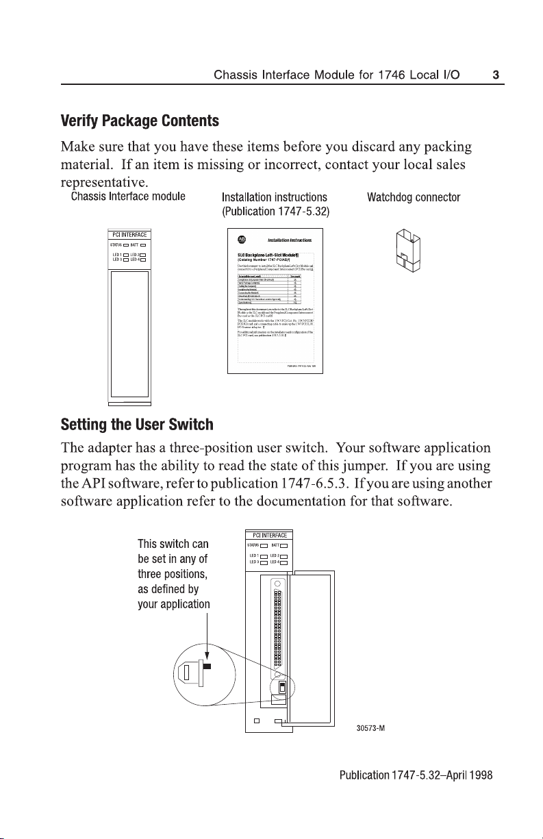
Use this document to install the Chassis Interface module for 1746
Local I/O and connect it to a PCI Bus card for 1746 Local I/O.
The Chassis Interface module works with the PCI Bus card
(Cat. No. 1747-PCIS/PCIS2) and a connecting cable to make up
the 1747 PCI Bus Interface.
To install the card, read:
Compliance to European Union Directives
Verify Package Contents
Setting the User Switch
Setting the Jumpers
Installing the Adapter
Selecting the Cable for Your Connections
Connecting the Adapter to the Scanner
Adapter LED Templates
Checking LED Indicators
General Operation
Understanding CSA Hazardous Location Approval
Specifications
See page:
2
3
3
4
6
6
7
8
9
11
12
14
In the instructional text of this document, we refer to the Chassis
Interface module as the adapter and the PCI Bus card as the scanner.
For additional information on the installation and configuration of the
PCI Bus card, see publication 1747-5.31.
Publication 1747-5.32–April 1998
Page 2

2 Chassis Interface Module for 1746 Local I/O
Compliance to European Union Directives
If this product bears the CE marking, it is approved for installation within
the European Union and EEA regions. It has been designed and tested to
meet the following directives.
EMC Directive
This product is tested to meet Council Directive 89/336/EEC
Electromagnetic Compatibility (EMC) and the following standards, in
whole or in part, documented in a technical construction file:
• EN 50081-2 EMC - Generic Emission Standard, Part 2 - Industrial
Environment
• EN 50082-2 EMC - Generic Immunity Standard, Part 2 - Industrial
Environment
This product is intended for use in an industrial environment.
Low Voltage Directive
This product is tested to meet Council Directive 73/23/EEC Low Voltage,
by applying the safety requirements of EN 61131-2 Programmable
Controllers, Part 2 - Equipment Requirements and Tests.
For specific information required by EN 61131-2, see the appropriate
sections in this publication, as well as the following Allen-Bradley
publications:
• Industrial Automation Wiring and Grounding Guidelines For Noise
Immunity, publication 1770-4.1
• Automation Systems Catalog, publication B111
This equipment is classified as open equipment and must be installed
(mounted) in an enclosure during operation as a means of providing safety
protection.
Publication 1747-5.32–April 1998
Page 3
Page 4
4 Chassis Interface Module for 1746 Local I/O
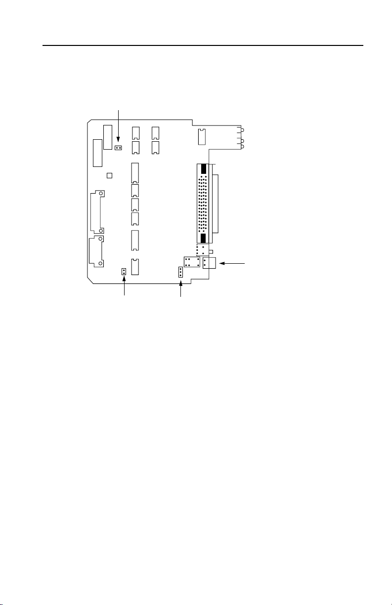
Setting the Jumper
The adapter has three separate jumpers on board.
Last State Jumper
Watchdog JumperUser Jumper
Watchdog Connector
(Internally connected to
the watchdog jumper
Last State Jumper
This jumper defines the state of I/O in case of a communication failure.
You must set the jumper to one of the following two settings:
• Last State –When communication with the scanner is lost (for
example, the cable is unplugged or the computer is turned off),
the 1746 I/O will hold their last state.
• Reset – When communication with the scanner is lost,
the 1746 I/O will be reset.
Watchdog Jumper
This jumper is internally connected to the watchdog connector. A detailed
explanation of this jumper’s usage is on the next page.
Publication 1747-5.32–April 1998
Page 5
Chassis Interface Module for 1746 Local I/O 5
User Jumper
Your software application program has the ability to read the state of this
jumper. If you are using the API software, refer to publication 1747-6.5.3.
If you are using another software application refer to the documentation
for that software.
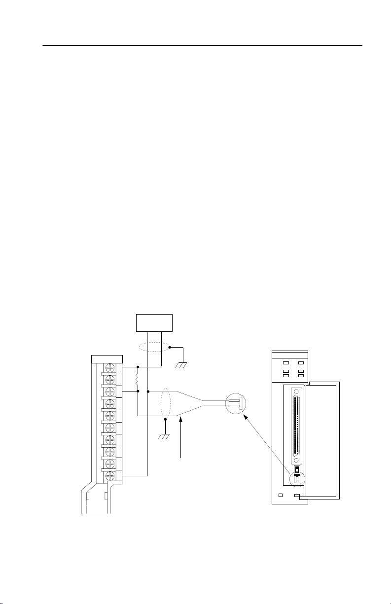
Using the Watchdog Jumper with the External Watchdog Connector
This jumper works in junction with the watchdog connector on the front
of the chassis interface module. The watchdog connector output is a solid
state switch that can switch a voltage range of 4.5V dc to 26.4V dc. The
connector plugs onto the front of the chassis interface module.
You need an external power supply to use the external watchdog. Adjust
the external load switched by the watchdog output to 20mA or less. The
watchdog output is normally off and turns on as a result of a watchdog
timeout condition due to an internal hardware failure. When this condition
occurs, a red indicator will light up on the status LED.
You must adhere to the watchdog output polarization to guarantee proper
operation.
dc or TTL input module
+ dc
input 0
input 1
input 2
input 3
input 4
input 5
input 6
input 7
- dc (common)
user power
supply
Ground the shields
at one end only.
Chassis mounting
bolt preferred.
common -
watchdog
contact +
Use 22-26 AWG
shielded twistedpair wire
Chassis
Interface
Module
contact
41165
Publication 1747-5.32–April 1998
Page 6

6 Chassis Interface Module for 1746 Local I/O
Installing the Adapter .
ATTENTION: Never install, remove, or connect cables
to the adapter with power applied to chassis.
!
Important: The adapter must be installed in the left slot of the chassis
as shown below.
Align circuit board with top
and bottom chassis guides.
21
Printed
Circuit
Board
30575–M 30574–M
Slide adapter into chassis
until adapter tabs ‘click’.
Locking tab
Selecting the Cable for Your Connections
The adapter must be connected to the scanner. Use one of the following
cables to make the connection:
• 3m interconnect cable (Cat. No. 1747-PCIC)
• 10m interconnect cable (Cat. No. 1747-PCIC2)
Publication 1747-5.32–April 1998
Page 7

Chassis Interface Module for 1746 Local I/O 7
Connecting the Adapter to the Scanner
To connect the adapter to the scanner, you:
1. Connect one end of the 1747-PCIC cable to the adapter.
2. Connect the other end of the 1747-PCIC cable to the scanner.
PCI Bus card
(scanner)
Chassis Interface module
(Adapter)
1747-PCIC cable
30576-M
The figure below shows an example of a connection between a Chassis
Interface module inside a local chassis and a PCI Bus card inside the
computer.
PCI Bus card (inside
the computer)
Personal Computer
1747-PCIC Cable
Chassis Interface
module (inside the
local chassis)
30173
Publication 1747-5.32–April 1998
Page 8

8 Chassis Interface Module for 1746 Local I/O
Adapter LED Templates
The adapter LED template allows you to create a custom template for
your application. Use the follow dimensions to create a template.
NOTES: Obtain these
parts to make a
custom LED.
1) Color is pantone
#431 grey over white
for opacity, opposite
adhesive side
2) Selective adhesive
around the perimeter
on the back
3) Clear windows
4) Protective cling
mask
5) Material .019 +/glossy polycarbonate
0.175 in.
+.002
0.200 in.
.002
+
0.350
.002
+
0.157 in.
0.400 in.
+.002
+.005
-.003
0.295 in.
.002
+
1.61 in.
+.002
0.078 in.
+.005
-.003
1.035 in.
.002
+
Initially, the LED template is easily removed from the front of the adapter.
After you have set the LED positions for your application, place the
display on the module and push it into place.
Publication 1747-5.32–April 1998
Page 9

Chassis Interface Module for 1746 Local I/O 9
Checking LED Indicators
PCI INTERFACE
STATUS BATT
LED 1 LED 2
LED 3 LED 4
STATUS
The STATUS indicator reports the status of the scanner. The following
table lists the LED states for STATUS:
This state:
Yellow The scanner is running POST. None
Flashing green The scanner is in idle mode and is
not scanning I/O.
Solid green The scanner is scanning I/O. None
Flashing red An I/O fault has occurred. Check software to identify
Solid red A scanner internal fault has
occurred.
Off The adapter is not powered up. Turn on p o w e r.
Means: Take this action:
None
fault condition.
Power system off and back on. If
the problem persists, service may
be required.
Publication 1747-5.32–April 1998
Page 10

10 Chassis Interface Module for 1746 Local I/O
BATT
The BATT indicator reports the health of the battery on the PCI scanner
board. The following table lists the LED states for BATT:
This state:
Off The battery is OK. None
Red The battery is low or dead. Replace the battery.
Means: Take this action:
LED 1, LED 2, LED 3, LED 4
Your application program can control the state of the four user LEDs on
the front of the adapter module. The default state is off. The following
table lists the possible LED states that your program can set.
This LED:
LED 1 & LED 2 Solid red
LED 3 & LED 4 Solid red
Can have these states: Take this action:
Flashing red
Solid green
Flashing green
Off
Solid green
Off
These actions are determined by
your specific application.
These actions are determined by
your specific application.
Publication 1747-5.32–April 1998
Page 11

Chassis Interface Module for 1746 Local I/O 11
During the power-on self test (POST), LED 1, LED 2, LED 3, and LED
4 indicate which test is running (if the STATUS LED is yellow) or which
test failed (if the STATUS LED is red). The following table lists the LED
patterns during POST.
This LED:
LED 1 Solid red
LED 2 Solid red
LED 3 Solid red
LED 4 Solid red
Can have these states: Which indicate these tests:
Flashing red
Solid green
Flashing green
Flashing red
Solid green
Flashing green
Solid green
Solid green
Software CRC checksum
Reserved
128K bytes RAM
Dual-port RAM
Backplane
Reserved
Reserved
Reserved
Reserved
Temperature sensor
Interrupt adapter
Timer
General Operation
The adapter has no microprocessor on board that scans or controls the
1746 backplane. The scanner board contains the I/O scanner
microprocessor and connects to the I/O backplane via the parallel cable
(1747-PCIC) and adapter module.
The control program running on the PC monitors and controls the 1746
I/O via the scanner’s dual port memory. All LED indicators on the adapter
are controlled by the scanner.
Publication 1747-5.32–April 1998
Page 12

12 Chassis Interface Module for 1746 Local I/O
Understand CSA Hazardous Location Approval
CSA certifies products for general use as well as for use in hazardous locations. Actual CSA
certification is indicated by the product label as shown below, and not by statements in any
user documentation.
Example of the CSA certification product label:
To comply with CSA certification for use in hazardous locations, the following information
becomes a part of the product literature for this CSA-certified industrial control product.
• This equipment is suitable for use in Class I, Division 2, Groups A, B, C, D, or non-hazardous locations
only.
• The products having the appropriate CSA markings (that is, Class I, Division 2, Groups A, B, C, D) are
certified for use in other equipment where the suitability of combination (that is, application or use) is
determined by the CSA or the local inspection office having jurisdiction.
Important: Due to the mo dular nature of a programmable control system, th e product with the highest
temperature rating determines the overall temperature code rating of a programmable
control system in a Class I, Division 2, location. The temperature code rating is marked
on the product label as shown.
Temperature code rating:
CL I, DIV 2
GP A,B,C,D
TEMP
CL I, DIV 2
GP A,B,C,D
TEMP
Look for temperature
code rating h ere.
The following warnings apply to products having CSA certification for use in hazardous locations.
WARNING: Explosion hazard--
• Substitution of components may impair suitability for Class I, Division 2.
• Do not replace components unless power has been switched off or the area is
known to be non-hazardous.
• Do not disconnect equipment unless power has been switched off or the area
is known to be non-hazardous.
• Do not disconnect connectors unless power has been switched off or the area
is known to be non-hazardous. Secure any user-supplied connectors that mate
to external circuit s on this equipment by using s crews, sliding latches, threaded
connectors, or oth er means such that any c onnection can withstand a 15 Newton
(3.4 lb.) separating force applied for a minimum of one minute.
• Batteries must only be changed in an area known to be non-hazardous.
CSA logo is a registered trademark of the Canadian Standards Association.
Publication 1747-5.32–April 1998
Page 13
Chassis Interface Module for 1746 Local I/O 13
Approbation d’utilisation dans des environments dangereux par la CSA
La CSA certifie des produits pour une utilisation générale aussi bien que pour une utilisation en
environnements dangereux. La certification CSA en vigueur est indiquée par l'étiquette produit
et non par des indications dans la documentation utilisateur.
Exemple d'étiquette de certification d'un produit
par la CSA :
Pour satisfaire à la certification CSA en environnements dangereux, les informations suivantes
font partie intégrante de la documentation des produits de commande industrielle certifiés.
• Cet équipement ne convient qu’à une utilisation dans des environnements de Classe I, Division 2,
Groupes A, B, C, D ou non dangereux.
• Les produits portant le marquage CSA approprié (c'est-à-dire Classe I, Division 2, Groupes A, B, C, D)
sont certifiés pour une utilisation avec d'autres équipements, les combinaisons d’applications et
d’utilisation étant déterminées par la CSA ou le bureau local d'inspection.
Important: De par la nature modulaire des systèmes de commande programmables, le produit ayant le
code de température le plus élevé détermine le code de température global du système dan s
un environnement de Classe I, Division 2. Le code de température est indiqué sur l'étiquette
produit.
Code de température :
CL I, DIV 2
GP A,B,C,D
TEMP
CL I, DIV 2
GP A,B,C,D
TEMP
Le code de tem pérature
est indiqué ici.
Les avertissements suivants s’appliquent aux produits ayant la certification CSA pour une utilisation dans des
environnements dangereux.
AVERTISSEMENT : Risque d’explosion --
• La subs titution de composants peut rendre ce matériel ina dapté à une utilisation
en environnement de Classe I, Division 2.
• Couper le courant ou s'assurer que l’environnement est classé non dangereux
avant de remplacer des composants.
• Couper le courant ou s’assurer que l’environnement est classé non dangereux
avant de débrancher l'équipement.
• Couper le courant ou s'assurer que l’environnement est classé non dangereux
avant de débrancher les connecteurs. Fixer tous les connecteurs fournis par
l'utilisateur pour se brancher aux circuits externes de cet appareil à l 'aide de
vis, loquets coulissants, connecteurs filetés ou autres, de sorte que les
connexions résistent à une force de séparation de 15 Newtons (1,5 kg - 3,4 lb.)
appliquée pendant au moins une minute.
• S'ass urer que l'environnement est classé non dangereux avant de changer le s piles.
Le sigle CSA e st une marque déposée de l a Canadian Sta ndards Assoc iation.
Publication 1747-5.32–April 1998
Page 14

14 Chassis Interface Module for 1746 Local I/O
Specifications
Adapter Location Left slot of a 1746 I/O chassis
Backplane Current 100mA @ 5V dc
Environmental Conditions
Wiring Category 2
Agency Certification
(when product or packaging is marked)
Slot Operating Temperature
Slot Storage Temperature
Relative Humidity
Vibration
Operating Shock
Storage Shock
0 to 60oC
-40o to 95oC
5-95% without condensation
Constant 10-60Hz, 0.015 in. displacement
Constant 60-2000Hz, 2.5G acceleration
30G
50G
U
listed
R
L
USC
marked for all applicable directives
Publication 1747-5.32–April 1998
Page 15

Chassis Interface Module for 1746 Local I/O 15
Publication 1747-5.32–April 1998
Page 16

16 Chassis Interface Module for 1746 Local I/O
•
Worldwide representation.
Argentina • Australia • Austria • Bahrain • Belgium • Brazil • Bulgaria • Canada • Chile • China, PRC •
Colombia • Costa Rica • Croatia • Cyprus • Czech Republic • Denmark • Ecuador • Egypt • El Salvador • Finland •
France • Germany • Greece • Guatemala • Honduras • Hong Kong • Hungary • Iceland • India • Indonesia •
Ireland • Israel • Italy • Jamaica • Japan • Jordan • Korea • Kuwait • Lebanon • Malaysia • Mexico • Netherlands
New Zealand • Norway • Pakistan • Peru • Philippines • Poland • Portugal • Puerto Rico • Qatar • Romania •
Russia-CIS • Saudi Arabia • Singapore • Slovakia • Slovenia • South Africa, Republic • Spain • Sweden •
Switzerland • Taiw a n • Thailand • Tur k ey • United Arab Emirates • United Kingdom • United States • Uruguay •
Venezuela • Yugoslavia
Allen-Bradley Headquarters, 1201 South Second Street, Milwaukee, WI 53204 USA,
Tel: (1) 414 382-2000 Fax: (1) 414 382-4444
.Publication 1747-5.32 – April 1998 PN 955131-21
Copyright 1998 Allen-Bradley, Inc. Printed in USA
 Loading...