

Page 1
Installation Instructions
Memory Module Adaptor for SLC 5/03 and Higher Processors
(Cat. No. 1747-M15, Series B)
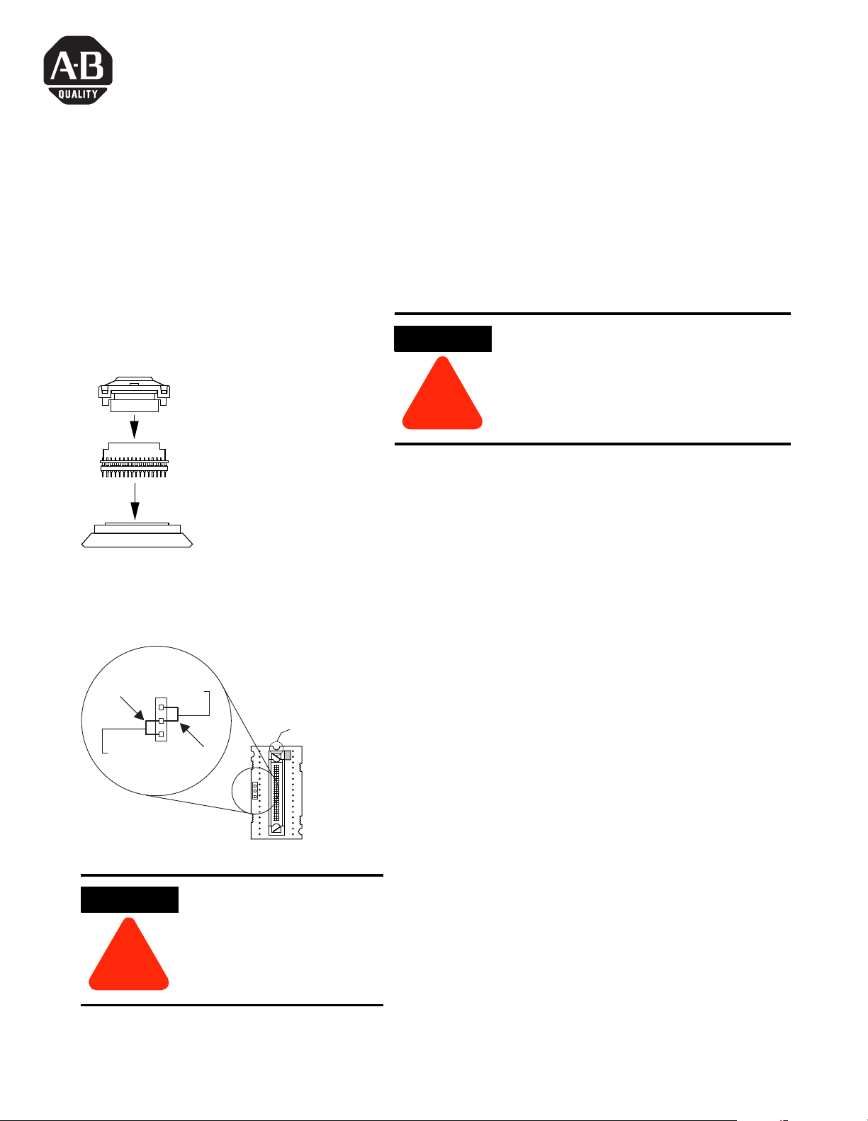
Orientation of the Memory
Module Adaptor
1747-M11
1747-M12, or
1747-M13
1747-M15
User-Supplied
PROM Programmer
Jumper Location
M12
A18
VPP
M13
J3
J3
M11
ATTENTION
PROMs are electrostatic sensitive devices.
Do not handle without proper grounding
precautions.
!
Memory Module Compatibility
The 1747-M15 Memory Module Adaptor can be used with
the 1747-M11, 1747-M12, 1747-M13 memory modules.
Installation Procedure
1. 1. Move jumper (J3) to the proper position for the
memory module to be programmed. For the
To p
A18
1747-M11 and 1747-M12 modules, the jumper must
connect VPP to the center pin. For the 1747-M13
module, the jumper must connect A18 to the center
pin.
VPP
ATTENTION
Incorrect J3 jumper position
can damage the memory
module or the PROM
programmer.
!
1 Publication 1747-IN061A-EN-P - May 2001
2. Gently connect the memory module to the adaptor.
(Align arrows marked on connectors.)
3. Check the orientation of the adaptor assembly. The
notch indicates the top of the adaptor.
4. Insert the adaptor assembly into the PROM
receptacle on your PROM programmer.
5. Program the memory module according to the
instructions provided with your PROM programmer.
Page 2

Publication 1747-IN061A-EN-P - May 2001 22 PN 40071-129-01(A)
Supersedes Publication 40063-18 8-01(A) - October 2001 Copyright © 2007 Rockwell Automation, Inc . All rights reserved. Printed in Singapore.
 Loading...