

Page 1
Installation Instructions
SLC 500 EtherNet/IP Adapter
Catalog Number
Topic Page
Important User Information 2
North American Hazardous Location Approval 4
Additional Resources 5
Overview 5
Install the Adapter Module in the Chassis 9
Connect Your Adapter to the Ethernet/IP Network through RJ-45 Connection 10
Troubleshoot with Status Indicators and Status Display 11
Specifications 15
1747-AENTR
Page 2
2 SLC 500 EtherNet/IP Adapter
IMPORTANT
Important User Information
Solid-state equipment has operational characteristics differing from those of electromechanical equipment.
Safety Guidelines for the Application, Installation and Maintenance of Solid State Controls (publication
SGI-1.1
available from your local Rockwell Automation sales office or online at
http://www.rockwellautomation.com/literature/
equipment and hard-wired electromechanical devices. Because of this difference, and also because of the
wide variety of uses for solid-state equipment, all persons responsible for applying this equipment must
satisfy themselves that each intended application of this equipment is acceptable.
In no event will Rockwell Automation, Inc. be responsible or liable for indirect or consequential damages
resulting from the use or application of this equipment.
The examples and diagrams in this manual are included solely for illustrative purposes. Because of the many
variables and requirements associated with any particular installation, Rockwell Automation, Inc. cannot
assume responsibility or liability for actual use based on the examples and diagrams.
No patent liability is assumed by Rockwell Automation, Inc. with respect to use of information, circuits,
equipment, or software described in this manual.
Reproduction of the contents of this manual, in whole or in part, without written permission of Rockwell
Automation, Inc., is prohibited.
Throughout this manual, when necessary, we use notes to make you aware of safety considerations.
WARNING: Identifies information about practices or circumstances that can cause an
explosion in a hazardous environment, which may lead to personal injury or death, property
damage, or economic loss.
ATTENTION: Identifies information about practices or circumstances that can lead to
personal injury or death, property damage, or economic loss. Attentions help you identify a
hazard, avoid a hazard and recognize the consequences.
) describes some important differences between solid-state
SHOCK HAZARD: Labels may be on or inside the equipment (for example, drive or motor)
to alert people that dangerous voltage may be present.
BURN HAZARD: Labels may be on or inside the equipment (for example, drive or motor) to
alert people that surfaces may reach dangerous temperatures.
Identifies information that is critical for successful application and understanding of
the product.
Publication 1747-IN521B-EN-E - January 2013
Page 3

Environment and Enclosure
ATTENTION: This equipment is intended for use in a Pollution Degree 2 industrial
environment, in overvoltage Category II applications (as defined in IEC 60664-1), at
altitudes up to 2000 m (6562 ft) without derating. This equipment is considered
Group 1, Class A industrial equipment according to IEC/CISPR 11. Without
appropriate precautions, there may be difficulties with electromagnetic compatibility
in residential and other environments due to conducted and radiated disturbances.
This equipment is supplied as open-type equipment. It must be mounted within an
enclosure that is suitably designed for those specific environmental conditions that
will be present and appropriately designed to prevent personal injury resulting from
accessibility to live parts. The enclosure must have suitable flame-retardant
properties to prevent or minimize the spread of flame, complying with a flame
spread rating of 5VA, or be approved for the application, if non-metallic. The interior
of the enclosure must be accessible only by the use of a tool. Subsequent sections of
this publication may contain additional information regarding specific enclosure type
ratings that are required to comply with certain product safety certifications.
In addition to this publication, see:
• Industrial Automation Wiring and Grounding Guidelines, Rockwell Automation
publication 1770-4.1
• NEMA Standard 250 and IEC 60529, as applicable, for explanations of the
degrees of protection provided by different types of enclosure.
, for additional installation requirements.
SLC 500 EtherNet/IP Adapter 3
Preventing Electrostatic Discharge
ATTENTION: This equipment is sensitive to electrostatic discharge, which can
cause internal damage and affect normal operation. Follow these guidelines when
you handle this equipment:
• Touch a grounded object to discharge potential static.
• Wear an approved grounding wriststrap.
• Do not touch connectors or pins on component boards.
• Do not touch circuit components inside the equipment.
• Use a static-safe workstation, if available.
• Store the equipment in appropriate static-safe packaging when not in use.
Publication 1747-IN521B-EN-E - January 2013
Page 4
4 SLC 500 EtherNet/IP Adapter
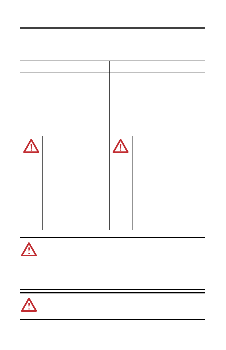
North American Hazardous Location Approval
The 1747-AENTR module is North American Hazardous Location approved.
The following information applies when operating
this equipment in hazardous locations:
Products marked "CL I, DIV 2, GP A, B, C, D" are
suitable for use in Class I Division 2 Groups A, B, C,
D, Hazardous Locations and nonhazardous locations
only. Each product is supplied with markings on the
rating nameplate indicating the hazardous location
temperature code. When combining products
within a system, the most adverse temperature
code (lowest "T" number) may be used to help
determine the overall temperature code of the
system. Combinations of equipment in your system
are subject to investigation by the local Authority
Having Jurisdiction at the time of installation.
EXPLOSION HAZARD
• Do not disconnect equipment unless
power has been removed or the area
is known to be nonhazardous.
• Do not disconnect connections to this
equipment unless power has been
removed or the area is known to be
nonhazardous. Secure any external
connections that mate to this
equipment by using screws, sliding
latches, threaded connectors, or other
means provided with this product.
• Substitution of any component may
impair suitability for Class I,
Division 2.
• If this product contains batteries, they
must only be changed in an area
known to be nonhazardous.
Informations sur l’utilisation de cet équipement en
environnements dangereux:
Les produits marqués "CL I, DIV 2, GP A, B, C, D" ne
conviennent qu'à une utilisation en environnements de
Classe I Division 2 Groupes A, B, C, D dangereux et non
dangereux. Chaque produit est livré avec des
marquages sur sa plaque d'identification qui indiquent
le code de température pour les environnements
dangereux. Lorsque plusieurs produits sont combinés
dans un système, le code de température le plus
défavorable (code de température le plus faible) peut
être utilisé pour déterminer le code de température
global du système. Les combinaisons d'équipements
dans le système sont sujettes à inspection par les
autorités locales qualifiées au moment de l'installation.
RISQUE D’EXPLOSION
• Couper le courant ou s'assurer que
l'environnement est classé non dangereux
avant de débrancher l'équipement.
• Couper le courant ou s'assurer que
l'environnement est classé non dangereux
avant de débrancher les connecteurs.
Fixer tous les connecteurs externes reliés
à cet équipement à l'aide de vis, loquets
coulissants, connecteurs filetés ou autres
moyens fournis avec ce produit.
• La substitution de tout composant peut
rendre cet équipement inadapté à une
utilisation en environnement de Classe I,
Division 2.
• S'assurer que l'environnement est classé
non dangereux avant de changer les piles.
WARNING: When you insert or remove the module while backplane power is on, an
electrical arc can occur. This could cause an explosion in hazardous location
installations.
Be sure that power is removed or the area is nonhazardous before proceeding.
Repeated electrical arcing causes excessive wear to contacts on both the module and
its mating connector. Worn contacts may create electrical resistance that can affect
module operation.
WARNING: When used in a Class I, Division 2, hazardous location, this equipment
must be mounted in a suitable enclosure with proper wiring method that complies
with the governing electrical codes.
Publication 1747-IN521B-EN-E - January 2013
Page 5

ATTENTION: Electrostatic discharge can damage semiconductor devices inside the
module. Do not touch the connector pins or other sensitive areas.
ATTENTION: This equipment must be powered from Allen-Bradley power supply
models 1746-P1, 1746-P2, 1746-P3, 1746-P4, 1746-P5, 1746-P6, or 1746-P7. Do not
use the 1746-P4 device in UL Class 1, Division 2, Hazardous Locations.
ATTENTION: Do not remove the protective debris strips until after the controller and
all other equipment in the panel near the module are mounted and wired. Remove
strips before operating the controller. Failure to remove strips before operating can
cause overheating.
ATTENTION: Be careful when stripping wires. Wire fragments that fall into the
controller could cause damage. Once wiring is complete, make sure the controller is
free of all metal fragments.
ATTENTION: Do not remove or replace the Adapter Module while power is applied.
Interruption of the backplane can result in unintentional operation or machine motion.
Additional Resources
Resource Description
SLC™ 500 EtherNet/IP Adapter
Programmable Controllers User Manual,
publication 1747-UM076
Industrial Automation Wiring and
Grounding Guidelines, publication 1770-4.1
A more detailed description of how to install and use your SLC™
500 EtherNet/IP Adapter.
More information on proper wiring and grounding techniques.
SLC 500 EtherNet/IP Adapter 5
If you would like a manual, you can:
• download a free electronic version from the Internet:
http://rockwellautomation.com/literature
• purchase a printed manual by contacting your local Allen-Bradley distributor or
Rockwell Automation representative
Overview
The SLC EtherNet/IP Adapter allows SLC I/O to be controlled by a CompactLogix or
ControlLogix processor. The module is intended for use when migrating existing SLC
controlled systems to a Logix-based controller.
This module does not support SLC I/O modules that require G files or any communication
modules that are attached to the same chassis as the adapter. See the 1747-AENTR User Manual,
publication 1747-UM076
Any Rockwell Automation CIP connection originating device can communicate and share I/O
data through the 1747-AENTR.
, for a complete list of modules that are supported by this module.
Publication 1747-IN521B-EN-E - January 2013
Page 6
6 SLC 500 EtherNet/IP Adapter
IMPORTANT
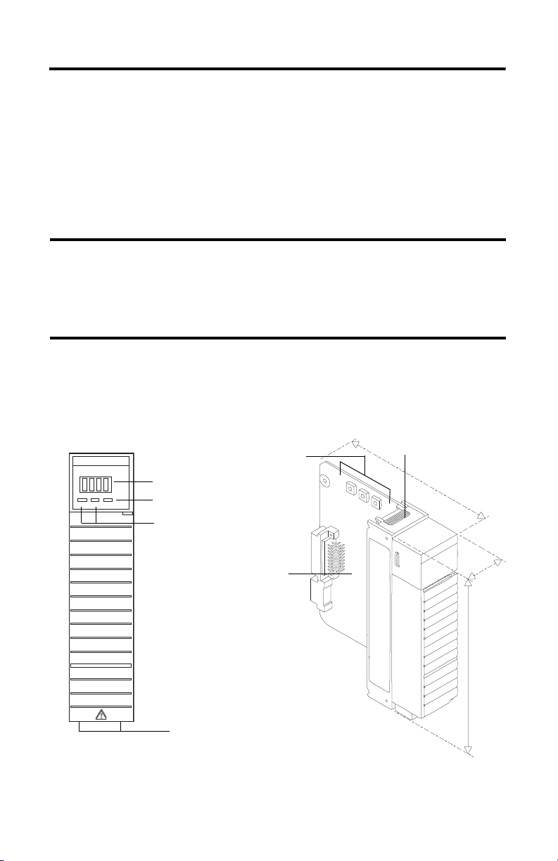
Ethernet Connectors (RJ-45)
Module status indictator
Link 1 and Link 2 status
indictators
Four character display
PCB
Front view
Latch
EtherNet/IP
switches
The 1747-AENTR adapter features :
• One exclusive owner connection per SLC module (the ability to connect to partial sets
of I/O and rack connections are not supported on firmware revision 1.001)
• Up to 5 Input Only connections per module
• Up to 5 Listen Only connections per module
• Up to 5 explicit messaging connections to the adapter
• Up to 5 consumers per multicast connection
On firmware revision 2.001 and later, the 1747-AENTR adapter additionally
supports direct connections to rack extensions, including:
• Up to 96 Class 1 connections;
• Up to 8 Class 3 connections.
Hardware Components
The adapter module consists of the following major components.
1747-AENT
5.15
LINK1 LINK2
MOD
Link 1 Link 2
Publication 1747-IN521B-EN-E - January 2013
1.37
5.72
Page 7

SLC 500 EtherNet/IP Adapter 7
1
8
8
1
Left side view Right side view
Bottom view
Ethernet connectors (RJ-45)
45844
45845
45846
Diagnostic Indicators
Health indicators are located on the front panel of the adapter module. They indicate both
normal operation and error conditions in your remote I/O system.
An alphanumeric display (net address/status) provides status code indications when an error
occurs during initialization or operation.
A complete description of the diagnostic indicators and status display and how to use them for
troubleshooting is explained on page 11.
Understand Messaging
Class 3 (Explicit Message) requests through the 1747-AENTR adapter to a specific I/O module
may not always receive a response from the I/O modules. In the case where the I/O module does
not reply to the request, the adapter responds with an error code indicating a time-out.
Establish I/O Connections
When you start a system and establish I/O connections, the outputs transition to the Idle state,
applying Idle state data before going to Run mode. This occurs even when the controller making
the connection is already in Run mode.
Publication 1747-IN521B-EN-E - January 2013
Page 8
8 SLC 500 EtherNet/IP Adapter
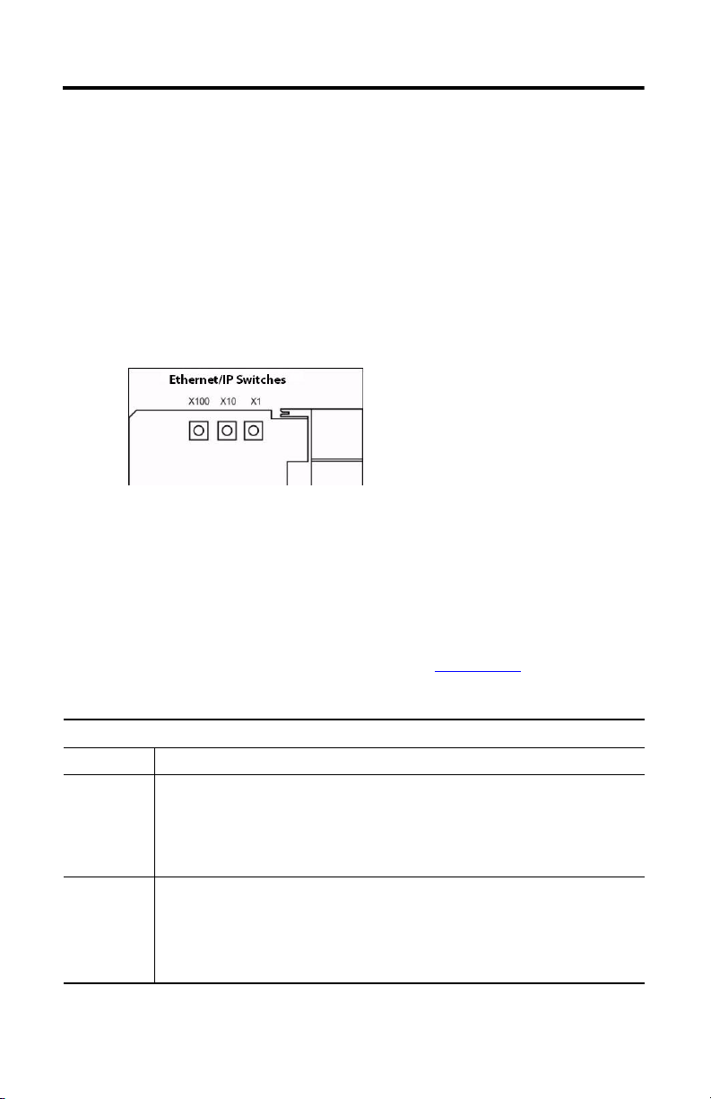
Set the Network Address
The network address switches are set to 999 and DHCP enabled, by default. You can set the
network Internet Protocol (IP) address in the following ways:
• Use the network address switches on the module.
• Use a Dynamic Host Configuration Protocol (DHCP) server, such as
Rockwell Automation BootP/DHCP.
• Retrieve the IP address from nonvolatile memory.
The adapter reads the network address switches first to determine if the switches are set to a valid
number. You set the node address by using the network address switches. Valid settings range
from 001…254.
When the switches are set to a valid number, the adapter’s IP address is 192.168.1.xxx (where xxx
represents the number set on the switches).
The adapter’s subnet mask is 255.255.255.0 and the gateway address is set to 0.0.0.0. The adapter
does not have a host name assigned, or use any Domain Name System when using the network
address switch settings.
If the switches are set to an invalid number (for example, 000 or a value greater than 254
excluding 888
Refer to publication SLC Ethernet/IP Adapter User Manual, 1747-UM076
for detailed information on IP address configuration.
(1)
), the adapter checks to see if DHCP is enabled.
,
DHCP Enabled and Not Enabled
If DHCP is Then the Adapter
Enabled Asks for an address from a DHCP server. The DHCP server also assigns other Transport
Not enabled Uses the IP address (along with other TCP configurable parameters) stored in nonvolatile
(1)
Setting the network switches to 888 restores default factory settings.
Control Protocol (TCP) parameters.
The 1747-AENTR factory default is DHCP enabled. When you apply power, the module sends
a message containing its hardware address to any DHCP server on the network. The
server(s) replies by sending a message with an appropriate IP address for the adapter. The
adapter responds by acknowledging to a server that it will use the offered IP address.
memory.
When the IP address assigned to the module, as indicated in the four-character dot matrix
status display, is changed through the DHCP configuration utility, the DHCP is disabled.
When power is cycled to the device, it uses the new configuration and implements the new
IP address.
Publication 1747-IN521B-EN-E - January 2013
Page 9

SLC 500 EtherNet/IP Adapter 9
TIP
Power supply
Card guide
Latch
Rockwell Automation recommends that you check or enable the option “Major
Fault On Controller If Connection Fails While in Run Mode” on both the
1747-AENTR device and supported 1746 I/O modules.
For a step-by-step guide on how to configure your adapter module through the
RSLogix 5000 or Logix Designer application, see the User Manual for the
SLC 500 EtherNet/IP Adapter, publication 1747-UM076
.
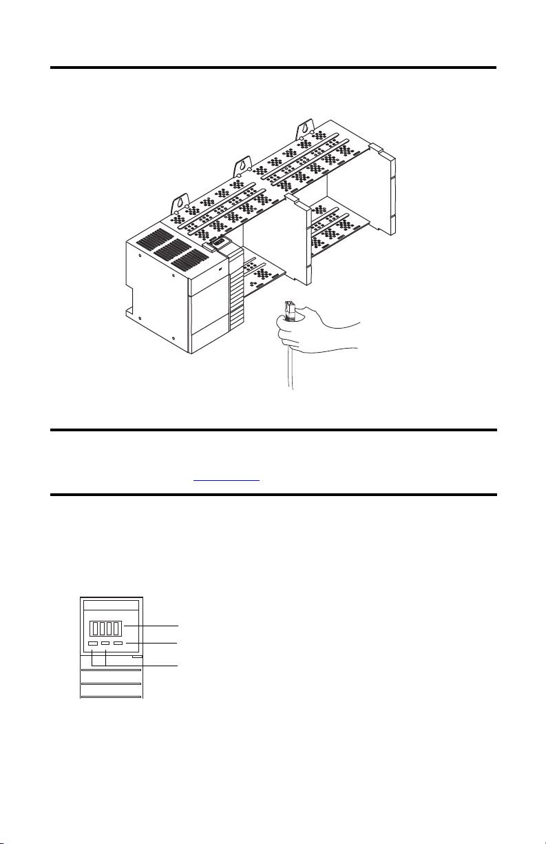
Install the Adapter Module in the Chassis
After you set the appropriate switch assemblies for your adapter module, follow these procedures
for installation.
Refer to the Industrial Controller Wiring and Grounding Guidelines publication 1770-4.1
proper grounding and wiring methods to use when installing your module.
1. Remove power from the I/O chassis before inserting (or removing) the module.
2. Align the circuit board with the chassis card guide in the left slot.
for
3. Install the module in slot 0 of the chassis by aligning the circuit board with the chassis
card guide.
The 1747-AENTR module must be installed only in slot 0 (leftmost slot)of the chassis.
4. Press firmly and evenly to seat the module in its backplane connectors. To remove the
module, press the releases at the top and bottom of the module and pull it out.
Publication 1747-IN521B-EN-E - January 2013
Page 10
10 SLC 500 EtherNet/IP Adapter
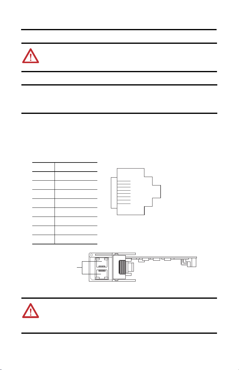
IMPORTANT
Signal
1 TxData+
2 TxData-
3 Recv Data+
4 Reserved
5 Reserved
6 Recv Data-
7 Reserved
8 Reserved
1747-AENTR module bottom view
RJ-45 connectors
RJ-45
45844
ATTENTION: Do not force the module into the backplane connector. If you cannot
seat the module with firm pressure, check the alignment. Forcing the module can
damage the backplane connector or the module.
The 1747-AENTR device should always be installed in Slot 0. There should
only be one 1747-AENTR device installed within the same rack or its
connected rack extensions for multiple chassis support.
Connect Your Adapter to the Ethernet/IP Network through RJ-45 Connection
Connect your 1747-AENTR adapter module to an Ethernet/IP network as shown below:
Wire the RJ-45 connectors as shown.
To connect the module to the network, follow these steps:
Publication 1747-IN521B-EN-E - January 2013
8
1
8
1
WARNING: If you connect or disconnect the communication cable with power
applied to this module or any device on the network, an electrical arc can occur.
This could cause an explosion in hazardous location installations. Be sure that
power is removed or the area is nonhazardous before proceeding.
Page 11
SLC 500 EtherNet/IP Adapter 11
IMPORTANT
1747-AENT
LINK1 LINK2
MOD
Module status indictator
Link 1 and Link 2 status
indictators
Four character display
1. Attach the cables with the RJ-45 connectors to the two Ethernet ports on the bottom of
the module.
2. Attach the other end of the cables to the devices in your network.
For information on how to install systems with rack extensions, you can refer
to the SLC 500 Modular Hardware Style User Manual,
publication 1747-UM011
.
Troubleshoot with Status Indicators and Status Display
The module has indicators on the front panel as shown below.
Use these indicators to troubleshoot the module.
The following table describes how to use the indicators to troubleshoot your module.
Publication 1747-IN521B-EN-E - January 2013
Page 12

12 SLC 500 EtherNet/IP Adapter
Interpret the Status Indicators
Indicator State Description
Module Off No power applied to device
Green Device operating normally
Flashing green Device has not been configured
Flashing red Recoverable fault.
Red Unrecoverable fault, may require device replacement
4 Character Display Displays IP address and module status description.
Link 1 or Link 2 Off No link established.
Solid green Link established @ 100 Mbps.
Flashing green Transmit or receive activity present on indicated port @ 100 Mbps.
Solid yellow Link established @ 10 Mbps.
Flashing yellow Transmit or receive activity present on indicated port @ 10 Mbps.
• IP Address switches do not match configuration in use.
• The device has completed a reset to factory default request
because the switches were set to 888 at powerup, and a power
cycle is required.
• The device is performing a firmware flash update.
See table, Four-character Status Display, for a description of all the
possible module status.
The four-character display indicates module status as shown in the table below.
Four-character Status Display
MOD LED Display Description Probable Cause Recommended
System startup
Red-green
flash
followed by
Solid Red
Green “OK”
Red 4-digit error hex code
Dotted display on Module is
(The first scroll cycle
displays the software
revision in the format
"Rev
majorRev.minorRev.
subMinorRev")
(For example, 0100 and
0101)
performing Power On
Self Test (POST)
POST is successful None None
POST Failure
(0100 = IOFPGA
failure)
(0101=ESFPGA
failure)
None None
The adapter has
either failed a
hardware test, or
gone into a state
from which it cannot
recover.
Publication 1747-IN521B-EN-E - January 2013
Action
Document the
error codes.
Power cycle the
adapter. Contact
Tec h ni ca l
Support.
Page 13

SLC 500 EtherNet/IP Adapter 13
Four-character Status Display
MOD LED Display Description Probable Cause Recommended
Action
Flashing Red “OK” alternates with
Runtime
Flashing green “OK” alternates with
Flashing red “Duplicate IP
the message:
“Factory Defaults
Restored. Change
Address Switches and
Reset.”
“Port x baud/dpx”
where:
x = port number 1 or 2
baud = Link rate, "10"
or "100"
dpx = “FULL” or
“HALF”
“OK” alternates with
“Port x down”
“OK” alternates with
“BOOTP
XX:XX:XX:XX:XX:XX”
or
“DHCP
XX:XX:XX:XX:XX:XX”
XX:XX:XX:XX:XX:XX”
“Flash update in
progress”
“Corrupt Certificate
Received”
“Corrupt Image
Received”
Factory defaults
restored
Module is
communicating.
Module is not
communicating.
Module is on
network waiting for
IP address
Module is not
communicating
Firmware update
mode
Firmware update
failure
Firmware update
failure
Node switches have
been set to 888. The
AENTR remains in
this mode until the
switches are
changed.
None None
Ethernet port is not
connected.
None Use RSLinx
The adapter has
detected a duplicate
node address on the
network.
Adapter firmware is
being updated via
ControlFlash update
utility
Firmware update
with invalid security
certificate
attempted.
Firmware update
with corrupt image
has been attempted.
Power off the
adapter. Remove
the adapter from
the chassis.
Change the node
address switch to
something other
than 888. Replace
the adapter in the
chassis, and
apply power.
Connect Ethernet
port.
BootP-DHCP
server or set IP
statically with
thumb wheel
switches.
Correct the
duplicate node to
address problem.
None
Ensure that you
have a valid
security
certificate to
download
firmware.
Make sure proper
ControlFLASH
update procedure
is followed. Retry
update.
Publication 1747-IN521B-EN-E - January 2013
Page 14

14 SLC 500 EtherNet/IP Adapter
Four-character Status Display
MOD LED Display Description Probable Cause Recommended
Action
Solid green <IP address> Module is
Solid Red “0001” Fatal error The adapter has
communicating and
working properly.
None None
failed a hardware
test, discovered too
many I/O racks
(greater than 3), or
reached a state from
which it cannot
recover.
Verify the correct
number of I/O
racks and power
cycle the adapter.
Contact Technical
Support if
problem persists.
Powerup Sequence
On powerup, the module performs the following in sequence.
1. RAM test
2. Flash image verification
3. Load image from flash and execute
4. Initialize LED and display handler
5. Initialize DLR
6. Check configuration switches and initialize TCPIP
7. Initialize 1746 backplane
8. Initialize main application
a. Create CIP Objects
b. Initialize Ethernet/IP stack
c. Create I/O manager
9. Initial DUP ID (duplicate ID) check
10. Initialize Web server
11. Enable I/O and messaging
Publication 1747-IN521B-EN-E - January 2013
Page 15

SLC 500 EtherNet/IP Adapter 15
Specifications
Ethernet Communication
Attribute Value
EtherNet communication rate 10/100 Mbits/s, half or full-duplex
Ethernet ports 2, configured as Embedded Switch
Ethernet network topologies supported Star, Tree, Daisy chain/Linear, and Ring
Ethernet connector RJ-45, Category 5
Ethernet cable Category 5: shielded or unshielded
General Specifications
Attribute Value
Module location Always at Slot 0 (leftmost slot) on chassis
Current consumption, backplane 470 mA @ 5V DC
Thermal dissipation 2.49 W = 8.4962 Btu (IT)/hour
Isolation voltage 50V (continuous), Basic Insulation Type
Dimensions (HxWxD), approx. 145.3 x 34.8 x 130.8 mm
Enclosure type rating None (open-style)
(1)
Wiring category
Weight, approx. 168 g (0.37 lbs.)
North American temp code T3C
(1)
Use this Conductor Category information for planning conductor routing. Refer to Industrial Automation
Wiring and Grounding Guidelines, publication 1770-4.1
(5.72 x 1.37 x 5.15 in.)
1 – on communication ports
.
Publication 1747-IN521B-EN-E - January 2013
Page 16

16 SLC 500 EtherNet/IP Adapter
Environmental Specifications
Attribute Value
Temperature, operating IEC 60068-2-1 (Test Ad, Operating Cold),
IEC 60068-2-2 (Test Bd, Operating Dry Heat),
IEC 60068-2-14 (Test Nb, Operating Thermal Shock):
0…60 °C (32…140 °F)
Temperature, nonoperating IEC 60068-2-1 (Test Ab, Unpackaged Non-operating Cold),
IEC 60068-2-2 (Test Bb, Unpackaged Non-operating Dry Heat),
IEC 60068-2-14 (Test Na, Unpackaged Non-operating Thermal Shock):
-40…85 °C (-40…185 °F)
Temperature, surrounding air, max 60 °C (140°F)
Relative humidity IEC 60068-2-30 (Test Db, Unpackaged Damp Heat): 5…95%
noncondensing
Vibration IEC 60068-2-6 (Test Fc, Operating): 2.5g @ 57…2000 Hz
Shock, operating IEC 60068-2-27 (Test Ea, Unpackaged Shock): 30 g
Shock, nonoperating IEC 60068-2-27 (Test Ea, Unpackaged Shock): 50 g
Emissions CISPR 11: Group 1, Class A
ESD immunity IEC 61000-4-2:
6 kV contact discharges
8 kV air discharges
Radiated RF immunity IEC 61000-4-3:
10V/m with 1KHz sine-wave 80% AM from 80…2000 MHz
10V/m with 200 Hz 50% Pulse 100% AM @ 900 MHz
10V/m, with 200 Hz 50% Pulse 100% AM @ 1890 MHz
10V/m with 1KHz sine-wave 80% AM from 2000…2700 MHz
EFT/B immunity IEC 61000-4-4:
±3 kV @ 5 kHz on communication ports
Surge transient immunity IEC 61000-4-5:
Conducted RF immunity IEC 61000-4-6:
±2 kV line-earth(CM) on communication ports
10V rms with 1 kHz sine-wave 80% AM from 150 kHz…80 MHz
Publication 1747-IN521B-EN-E - January 2013
Page 17

Certifications
SLC 500 EtherNet/IP Adapter 17
Certification (when
product is marked)
Valu e
(1)
c-UL-us UL Listed Industrial Control Equipment, certified for US and Canada.
See UL File E322657.
UL Listed for Class I, Division 2 Group A, B, C, D Hazardous Locations, certified
for U.S. and Canada. See UL File E334470.
CE European Union 2004/108/EC EMC Directive, compliant with:
EN 61326-1; Meas./Control/Lab., Industrial Requirements
EN 61000-6-2; Industrial Immunity
EN 61000-6-4; Industrial Emissions
EN 61131-2; Programmable Controllers (Clause 8, Zone A & B)
C-Tick Australian Radiocommunications Act, compliant with:
AS/NZS CISPR 11; Industrial Emissions
EtherNet/IP ODVA conformance tested to EtherNet/IP specifications
KC Korean Registration of Broadcasting and Communications Equipment,
compliant with:
Article 58-2 of Radio Waves Act, Clause 3
(1)
See the Product Certification link at http://www.rockwellautomation.com/products/certification/ for Declaration of
Conformity, Certificates, and other certification details.
Publication 1747-IN521B-EN-E - January 2013
Page 18

18 SLC 500 EtherNet/IP Adapter
Notes:
Publication 1747-IN521B-EN-E - January 2013
Page 19

SLC 500 EtherNet/IP Adapter 19
Publication 1747-IN521B-EN-E - January 2013
Page 20

Rockwell Automation Support
Rockwell Automation provides technical information on the Web to assist you in using its products. At
http://www.rockwellautomation.com/support/
technical and application notes, sample code and links to software service packs, and a MySupport feature that
you can customize to make the best use of these tools.
For an additional level of technical phone support for installation, configuration and troubleshooting, we offer
TechConnect support programs. For more information, contact your local distributor or Rockwell Automation
representative, or visit http://www.rockwellautomation.com/support/
Installation Assistance
If you experience a problem within the first 24 hours of installation, please review the information that's
contained in this manual. You can also contact a special Customer Support number for initial help in getting your
product up and running.
United States or Canada 1.440.646.3434
Outside United States
or Canada
Use the Worldwide Locator
http://www.rockwellautomation.com/support/americas/phone_en.html
your local Rockwell Automation representative.
New Product Satisfaction Return
Rockwell Automation tests all of its products to ensure that they are fully operational when shipped from the
manufacturing facility. However, if your product is not functioning and needs to be returned, follow these
procedures.
, you can find technical manuals, a knowledge base of FAQs,
.
at
, or contact
United States
Outside United States
Contact your distributor. You must provide a Customer Support case number (call the
phone number above to obtain one) to your distributor to complete the return process.
Please contact your local Rockwell Automation representative for the return
procedure.
Documentation Feedback
Your comments will help us serve your documentation needs better. If you have any suggestions on how to
improve this document, complete this form, publication RA-DU002
http://www.rockwellautomation.com/literature/
Allen-Bradley, Rockwell Software, Rockwell Automation, SLC, and Te chConnect are trademarks of Rockwell Automation, Inc.
Trademarks not belonging to Rockwell Automation are property of their respective companies.
Rockwell Otomasyon Ticaret A.Ş., Kar Plaza İş Merkezi E Blok Kat:6 34752 İçerenköy, İstanbul, Tel : +90 (216) 5698400
.
Publication 1747-IN521B-EN-E - January 2013
Supersedes Publication 1747-IN521A-EN-E - February 2012 Copyright © 2013 Rockwell Automation, Inc. All rights reserved.
, available at
 Loading...