

Page 1

ControlNet™
Adapter Module
(Catalog Numbers 1747-ACN15,
1747-ACNR15)
User Manual
Page 2
Important User Information
Because of the variety of uses for the products described in this publication,
those responsible for the application and use of this control equipment must
satisfy themselves that all necessary steps have been taken to assure that each
application and use meets all performance and safety requirements, including
any applicable laws, regulations, codes and standards.
The illustrations, charts, sample programs and layout examples shown in this
guide are intended solely for purposes of example. Since there are many
variables and requirements associated with any particular installation,
Allen-Bradley does not assume responsibility or liability (to include intellectual
property liability) for actual use based upon the examples shown in this
publication.
Allen-Bradley publication SGI-1.1, Safety Guidelines for the Application,
Installation and Maintenance of Solid-State Control (available from your local
Allen-Bradley office), describes some important differences between solid-state
equipment and electromechanical devices that should be taken into
consideration when applying products such as those described in this
publication.
Reproduction of the contents of this copyrighted publication, in whole or part,
without written permission of Rockwell Automation, is prohibited.
Throughout this manual we use notes to make you aware of safety
considerations:
ATTENTION
Identifies information about practices or circumstances that
can lead to personal injury or death, property damage or
economic loss
!!!!
Attention statements help you to:
• identify a hazard
• avoid a hazard
• recognize the consequences
IMPORTANT
ControlNet and SLC 500 are trademarks of Rockwell Automation.
PLC-5 is a registered trademark of Rockwell Automation.
Identifies information that is critical for successful
application and understanding of the product.
Page 3

Table of Contents
Preface
Introducing the ControlNet
Adapter Module
Installing Your ControlNet Adapter
Module
Who Should Use this Manual . . . . . . . . . . . . . . . . . . . . . . . . . . . . . P-1
Purpose of this Manual . . . . . . . . . . . . . . . . . . . . . . . . . . . . . . . . . . P-1
Related Documentation . . . . . . . . . . . . . . . . . . . . . . . . . . . . . . P-1
Common Techniques Used in this Manual. . . . . . . . . . . . . . . . . . . P-1
Rockwell Automation Support . . . . . . . . . . . . . . . . . . . . . . . . . . . . P-2
Local Product Support . . . . . . . . . . . . . . . . . . . . . . . . . . . . . . . P-2
Technical Product Assistance. . . . . . . . . . . . . . . . . . . . . . . . . . . P-2
Your Questions or Comments on this Manual . . . . . . . . . . . . . P-2
Chapter 1
Chapter Objectives . . . . . . . . . . . . . . . . . . . . . . . . . . . . . . . . . . . . . 1-1
Module Description and Features . . . . . . . . . . . . . . . . . . . . . . . . . . 1-1
Hardware Components . . . . . . . . . . . . . . . . . . . . . . . . . . . . . . . . . . 1-1
Diagnostic Indicators . . . . . . . . . . . . . . . . . . . . . . . . . . . . . . . . 1-2
Network Access Port (NAP) . . . . . . . . . . . . . . . . . . . . . . . . . . . 1-2
ControlNet Connectors . . . . . . . . . . . . . . . . . . . . . . . . . . . . . . 1-3
Network Address Switch Assemblies . . . . . . . . . . . . . . . . . . . . . 1-3
Chapter 2
Chapter Objectives . . . . . . . . . . . . . . . . . . . . . . . . . . . . . . . . . . . . . 2-1
Compliance to European Union Directives. . . . . . . . . . . . . . . . . . . 2-1
EMC Directive . . . . . . . . . . . . . . . . . . . . . . . . . . . . . . . . . . . . . 2-1
Low Voltage Directive. . . . . . . . . . . . . . . . . . . . . . . . . . . . . . . . 2-2
Determining Power Requirements . . . . . . . . . . . . . . . . . . . . . . . . . 2-2
Setting the Network Address Switches. . . . . . . . . . . . . . . . . . . . . . . 2-2
Installing the Adapter Module in the Chassis . . . . . . . . . . . . . . . . . 2-3
Connecting Your Adapter to the ControlNet Network . . . . . . . 2-4
Connecting Programming Terminals to the Network via the NAP . 2-6
Powerup Sequence . . . . . . . . . . . . . . . . . . . . . . . . . . . . . . . . . . . . . 2-7
Chapter 3
Planning to Use Your ControlNet
Adapter Module
i Publication 1747-UM003 A-EN-P
Chapter Objectives . . . . . . . . . . . . . . . . . . . . . . . . . . . . . . . . . . . . . 3-1
Compatible 1746 and 1747 I/O Modules . . . . . . . . . . . . . . . . . . . . 3-1
Overview of Adapter Operation . . . . . . . . . . . . . . . . . . . . . . . . . . . 3-2
Software Requirements . . . . . . . . . . . . . . . . . . . . . . . . . . . . . . . 3-2
Rack and Module Connections . . . . . . . . . . . . . . . . . . . . . . . . . 3-3
Optimizing SLC ControlNet Adapter Rack Connections . . . . . 3-4
Module Keying . . . . . . . . . . . . . . . . . . . . . . . . . . . . . . . . . . . . . 3-5
Output Operation During Fault and Idle Modes . . . . . . . . . . . 3-6
Understanding ControlNet I/O . . . . . . . . . . . . . . . . . . . . . . . . . . . 3-6
Scheduled Data-Transfer Connections on a
ControlNet Network. . . . . . . . . . . . . . . . . . . . . . . . . . . . . . . . . 3-6
Page 4

Table of Contents ii
Application Examples
Chapter 4
Example 1 . . . . . . . . . . . . . . . . . . . . . . . . . . . . . . . . . . . . . . . . . . . . 4-2
Hardware Setup . . . . . . . . . . . . . . . . . . . . . . . . . . . . . . . . . . . . 4-2
Configuring The ControlNet Network with
RSNetWorx™ for ControlNet . . . . . . . . . . . . . . . . . . . . . . . . . 4-3
Create a Ladder Logic Program . . . . . . . . . . . . . . . . . . . . . . . . 4-10
Example 2 . . . . . . . . . . . . . . . . . . . . . . . . . . . . . . . . . . . . . . . . . . . 4-11
Hardware Setup . . . . . . . . . . . . . . . . . . . . . . . . . . . . . . . . . . . 4-11
Configuring The ControlNet Network with
RSNetWorx™ for ControlNet . . . . . . . . . . . . . . . . . . . . . . . . 4-12
Create a Ladder Program. . . . . . . . . . . . . . . . . . . . . . . . . . . . . 4-20
Example 3 . . . . . . . . . . . . . . . . . . . . . . . . . . . . . . . . . . . . . . . . . . . 4-21
Hardware Setup . . . . . . . . . . . . . . . . . . . . . . . . . . . . . . . . . . . 4-21
Configuring The ControlNet Network with
RSNetWorx™ for ControlNet . . . . . . . . . . . . . . . . . . . . . . . . 4-22
Create a Ladder Logic Program . . . . . . . . . . . . . . . . . . . . . . . . 4-30
Example 4 . . . . . . . . . . . . . . . . . . . . . . . . . . . . . . . . . . . . . . . . . . . 4-31
Hardware Setup . . . . . . . . . . . . . . . . . . . . . . . . . . . . . . . . . . . 4-31
Configuring The ControlNet Network with
RSNetWorx™ for ControlNet . . . . . . . . . . . . . . . . . . . . . . . . 4-32
Create Ladder Logic and Basic Module Programs . . . . . . . . . . 4-43
Example 5 . . . . . . . . . . . . . . . . . . . . . . . . . . . . . . . . . . . . . . . . . . . 4-46
Hardware Setup . . . . . . . . . . . . . . . . . . . . . . . . . . . . . . . . . . . 4-46
Configuring The ControlNet Network with
RSNetWorx for ControlNet . . . . . . . . . . . . . . . . . . . . . . . . . . 4-47
Create a Ladder Logic Program . . . . . . . . . . . . . . . . . . . . . . . . 4-57
Troubleshooting
Specifications
Understanding Your SLC 500/1746
Control System
Publication 1747-UM003A-EN-P
Chapter 5
Chapter Objectives . . . . . . . . . . . . . . . . . . . . . . . . . . . . . . . . . . . . . 5-1
Troubleshooting With the Status Indicators and Status Display . . . 5-1
Health Indicators and Display Mnemonics . . . . . . . . . . . . . . . . 5-2
ControlNet Status Indicators . . . . . . . . . . . . . . . . . . . . . . . . . . . . . 5-3
Appendix A
Appendix B
Selecting Your SLC 500/1746 Control Power Supply. . . . . . . . . . . B-1
Power Supply Specifications . . . . . . . . . . . . . . . . . . . . . . . . . . . B-2
SLC 500 System Installation Recommendations . . . . . . . . . . . . . . . B-6
Typical Installation . . . . . . . . . . . . . . . . . . . . . . . . . . . . . . . . . . B-6
Selecting an Enclosure. . . . . . . . . . . . . . . . . . . . . . . . . . . . . . . . B-6
Spacing Considerations . . . . . . . . . . . . . . . . . . . . . . . . . . . . . . . B-7
Preventing Excessive Heat . . . . . . . . . . . . . . . . . . . . . . . . . . . . . B-8
Wiring Layout. . . . . . . . . . . . . . . . . . . . . . . . . . . . . . . . . . . . . . B-8
Page 5

Table of Contents iii
Grounding Guidelines. . . . . . . . . . . . . . . . . . . . . . . . . . . . . . . . B-9
Master Control Relay . . . . . . . . . . . . . . . . . . . . . . . . . . . . . . . B-11
Emergency-Stop Switches . . . . . . . . . . . . . . . . . . . . . . . . . . . . B-13
Common Power Source . . . . . . . . . . . . . . . . . . . . . . . . . . . . . B-15
Loss of Power Source. . . . . . . . . . . . . . . . . . . . . . . . . . . . . . . . B-16
Input States on Power Down . . . . . . . . . . . . . . . . . . . . . . . . . B-16
Other Types of Line Conditions . . . . . . . . . . . . . . . . . . . . . . . B-16
Power Conditioning Considerations . . . . . . . . . . . . . . . . . . . . B-16
Special Considerations. . . . . . . . . . . . . . . . . . . . . . . . . . . . . . . B-18
Output Contact Protection . . . . . . . . . . . . . . . . . . . . . . . . . . . B-20
Mounting Your Control System . . . . . . . . . . . . . . . . . . . . . . . . . . B-21
Mounting Modular Hardware Style Units. . . . . . . . . . . . . . . . B-21
Installing Your I/O Module . . . . . . . . . . . . . . . . . . . . . . . . . . . . . B-25
Features of an SLC 500 I/O Module. . . . . . . . . . . . . . . . . . . . B-25
Definition of Sinking and Sourcing. . . . . . . . . . . . . . . . . . . . . B-26
Inserting I/O Modules . . . . . . . . . . . . . . . . . . . . . . . . . . . . . . B-28
Removing I/O Modules . . . . . . . . . . . . . . . . . . . . . . . . . . . . . B-30
Wiring the I/O Modules . . . . . . . . . . . . . . . . . . . . . . . . . . . . . . . . B-31
Using Removable Terminal Blocks . . . . . . . . . . . . . . . . . . . . . B-32
Calculating Heat Dissipation for Your Control System. . . . . . . . . B-34
Module Heat Dissipation: Calculated Watts
vs. Maximum Watts . . . . . . . . . . . . . . . . . . . . . . . . . . . . . . . . B-34
Calculating the Power Supply Loading . . . . . . . . . . . . . . . . . . B-35
Determining the Power Supply Dissipation. . . . . . . . . . . . . . . B-38
Glossary
Index
Publication 1747-UM003 A-EN-P
Page 6

Table of Contents iv
Publication 1747-UM003A-EN-P
Page 7
Preface
Read this preface to familiarize yourself with the rest of the manual. It provides
information concerning:
• who should use this manual
• the purpose of this manual
• related documentation
• conventions used in this manual
• Allen-Bradley support
Who Should Use this Manual
Purpose of this Manual
Use this manual if you are responsible for designing, installing, programming, or
troubleshooting control systems that use the ControlNet Adapter Module.
You should have a basic understanding of electrical circuitry and familiarity with
relay logic. If you do not, obtain the proper training before using this product.
This manual is a reference guide for the ControlNet Adapter Module. It describes
the procedures you use to install, program and troubleshoot your module. This
manual also includes several application examples.
Related Documentation
The following documents contain additional information concerning
Allen-Bradley products. To obtain a copy, contact your local Allen-Bradley office or
distributor.
Publication Publication
Number
ControlNet PLC-5 Programmable Controllers User Manual Phase 1.5 1785-6.5.22
ControlNet Cable System Component List AG-2.2
ControlNet Cable System Planning and Installation Manual 1786-6.2.1
ControlNet Coax Tap Installation Instructions 1786-2.3
ControlNet Network Access Cable Installation Instructions 1786-2.6
ControlNet Repeater Installation Instructions 1786-2.7
Industrial Automation Wiring and Grounding Guidelines 1770-4.1
SLC 500™ Modular Hardware Style User Manual 1747-6.2
ControlNet Scanner Module Reference Manual 1747-6.23
Common Techniques Used in this Manual
1 Publication 1747-UM003 A-EN-P
The following conventions are used throughout this manual:
• Bulleted lists such as this one provide information, not procedural steps.
• Numbered lists provide sequential steps or hierarchical information.
• Italic type is used for emphasis.
Page 8

Preface 2
Rockwell Automation Support
Rockwell Automation offers support services worldwide, with over 75 Sales/
Support Offices, 512 authorized Distributors and 260 authorized Systems
Integrators located throughout the United States alone, plus Rockwell Automation
representatives in every major country in the world.
Local Product Support
Contact your local Rockwell Automation representative for:
• sales and order support
• product technical training
• warranty support
• support service agreements
Technical Product Assistance
If you need to contact Rockwell Automation for technical assistance, please review
the Troubleshooting appendix in your controller’s User Manual first. Then call your
local Rockwell Automation representative.
Your Questions or Comments on this Manual
If you find a problem with this manual, or you have any suggestions for how this
manual could be made more useful to you, please contact us at the address below:
Rockwell Automation
Control and Information Group
Technical Communication, Dept. A602V
P.O. Box 2086
Milwaukee, WI 53201-2086
or visit our internet page at:
http://www.rockwellautomation.com
Publication 1747-UM003A-EN-P
Page 9

Chapter
1
Introducing the ControlNet Adapter Module
Chapter Objectives
Module Description and Features
This chapter describes the ControlNet adapter modules (cat. no. 1747-ACN15
and 1747-ACNR15):
• features
• hardware components, including
– diagnostic indicators
– network access port (NAP)
– ControlNet connectors
– network address switch assemblies
The 1747-ACN15 and 1747-ACNR15 adapters control remote 1746 I/O on
the ControlNet network. The ControlNet network is a communication
architecture that allows the exchange of messages between ControlNet
products compliant with the CI specification.
The 1747-ACN15 and 1747-ACNR15 adapters features include:
• high-speed data transfer
• diagnostic messages
• local communication network access through the network access port
(NAP)
• redundant media (1747-ACNR15 only)
Hardware Components
1 Publication 1747-UM003 A-EN-P
The adapter module consists of the following major components:
• ControlNet status indicators
• status display
• network access port (NAP)
• ControlNet connectors (one on 1747-ACN15; two on 1747-ACNR15)
• module net address switch assemblies (on top of module)
Page 10
1-2 Introducing the ControlNet Adapter Module
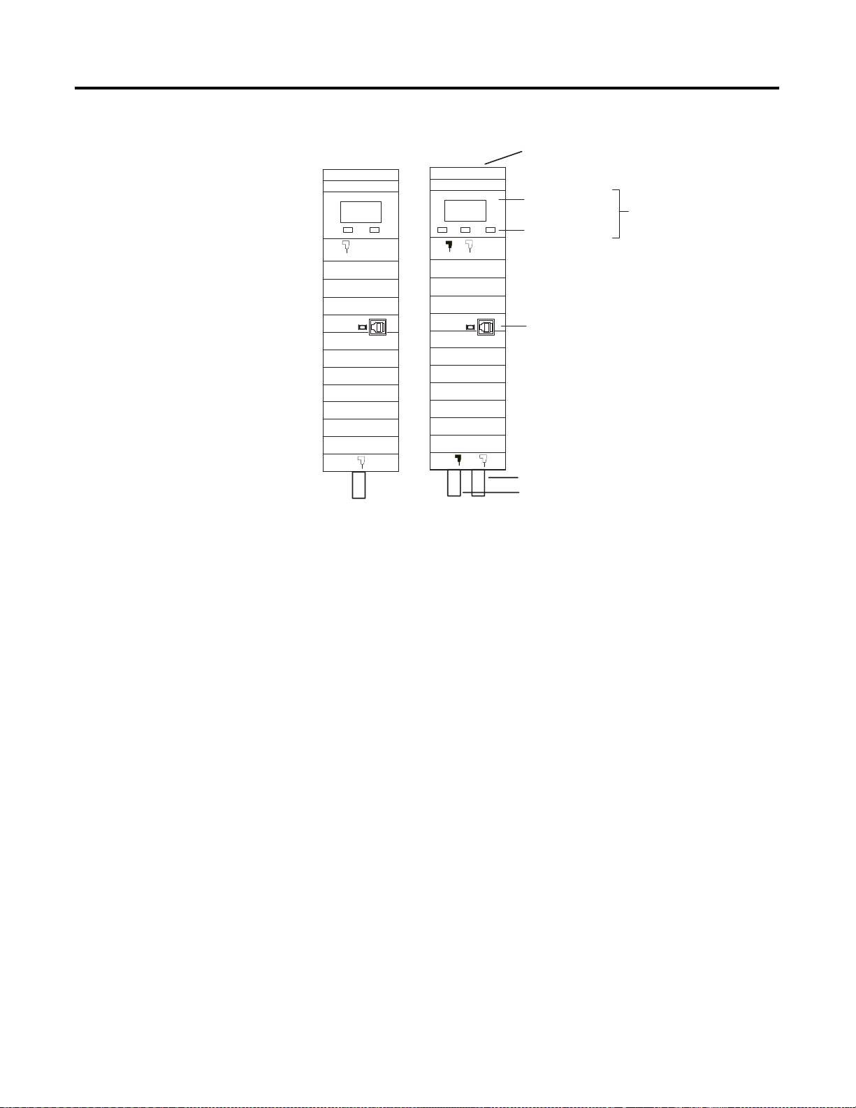
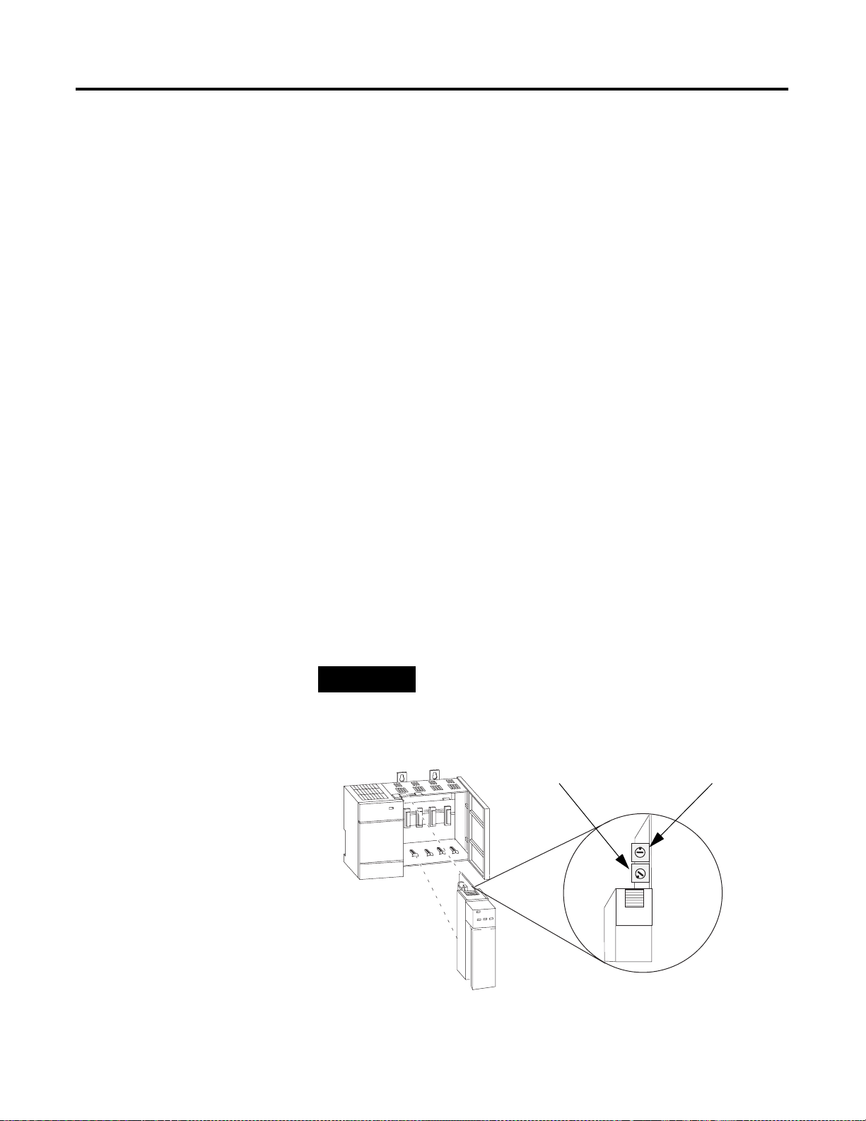
Figure 1.1 ControlNet Adapter Module
Module Network Address Switches
(accessible through top of module)
1747-ACN15
ADDRESS/STATUS
OK OK
A
ADDRESS/STATUS
BAA
B
Diagnostic Indicators
Status Display and
Net Address
Health Indicators
ControlNet Status Indicators
Network Access Port (NAP)
1747-ACNR15
A
ControlNet Media Port
ControlNet Redundant Media Port (1747-ACNR15 only)
Diagnostic Indicators
Health indicators are located on the front panel of the adapter module,
See Figure 1.1. They show both normal operation and error conditions in your
remote I/O system.
In addition, an alphanumeric display (net address/status) provides status code
indications when an error occurs during initialization or operation.
A complete description of the diagnostic indicators and status display and how
to use them for troubleshooting is explained in Chapter 5.
Network Access Port (NAP)
The network access port provides a bidirectional electrical interface for
programming, maintenance, and I/O monitoring devices in both redundant
and non-redundant connections. See Figure 1.1 connecting programming
terminals to the network using the NAP above.
Publication 1747-UM003A-EN-P
Page 11
Introducing the ControlNet Adapter Module 1-3
ControlNet Connectors
Cable connection to the module is through standard BNC connectors on the
module frontplate.
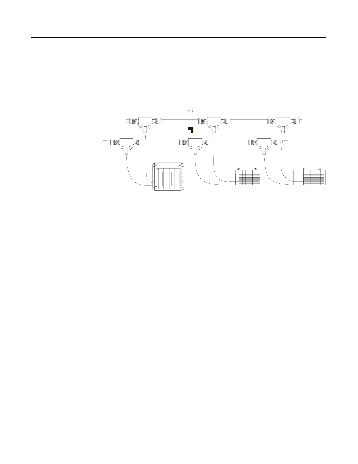
Figure 1.2 Redundant Media System
Terminator
Terminator
trunkline A =
trunkline B =
PLC-5C or SLC 5/02 or later
with 1747-SCNR
(1) End device supporting redundant cabling is a 1747-ACNR15.
A
Terminator
B
Terminator
end device
(1)
end device
(1)
Refer to the ControlNet Cable System Planning and Installation User Manual,
publication 1786-6.2.1 for more information.
Network Address Switch Assemblies
You must set two switch assemblies to configure your adapter module with its
unique network address. You access these switches through the top of the
module. Figure 1.3 shows the location of the switches. These switches are read
on powerup to establish the network address of the module. Network address
switch settings are described in Chapter 2.
For optimum throughput, assign sequential addresses to ControlNet nodes.
Publication 1747-UM003 A-EN-P
Page 12

1-4 Introducing the ControlNet Adapter Module
Publication 1747-UM003A-EN-P
Page 13

Chapter
2
Installing Your ControlNet Adapter Module
Chapter Objectives
Compliance to European Union Directives
This chapter describes the procedures for installing your ControlNet adapter
module. These include:
• European Directive compliance
• determining power requirements
• setting the network address switches
• setting the I/O chassis switches
• installing the adapter module in the chassis
• connecting programming terminals to the network via the network access
port (NAP)
• powerup sequence
For general installation guidelines, see SLC 500 System Installation
Recommendations on page B-6. If this product has the CE mark it is approved
for installation within the European Union and EEA regions. It has been
designed and tested to meet the following directives.
EMC Directive
This product is tested to meet Council Directive 89/336/EEC Electromagnetic
Compatibility (EMC) and the following standards, in whole or in part,
documented in a technical construction file:
• EN 50081-2
EMC - Generic Emission Standard, Part 2 - Industrial Environment
• EN 50082-2
EMC - Generic Immunity Standard, Part 2 - Industrial Environment
This product is intended for use in an industrial environment.
1 Publication 1747-UM003 A-EN-P
Page 14
2-2 Installing Your ControlNet Adapter Module
Low Voltage Directive
This product is tested to meet Council Directive 73/23/EEC Low Voltage, by
applying the safety requirements of EN 61131-2 Programmable Controllers,
Part 2 - Equipment Requirements and Tests.
For specific information required by EN 61131-2, see the appropriate sections
in this publication, as well as the following Allen-Bradley publications:
•
Industrial Automation Wiring and Grounding Guidelines For Noise
Immunity, publication 1770-4.1
•
Automation Systems Catalog, publication B111
Determining Power Requirements
Setting the Network Address Switches
The ControlNet adapter module requires a maximum backplane current of
900 mA at 5V dc. Remember to add this amount to other current
requirements for your I/O chassis.
The switches on the top of the adapter module determine the network address
of the adapter. The two switches are:
• the ten’s switch
• the one’s switch
The combination of these switches allows selection of network addresses from
01 to 99.
NOTE
Figure 2.1 Setting the Network Address
00 is an invalid number.
Ten ’s
Selection
One’s
Selection
Publication 1747-UM003A-EN-P
Page 15
Installing Your ControlNet Adapter Module 2-3
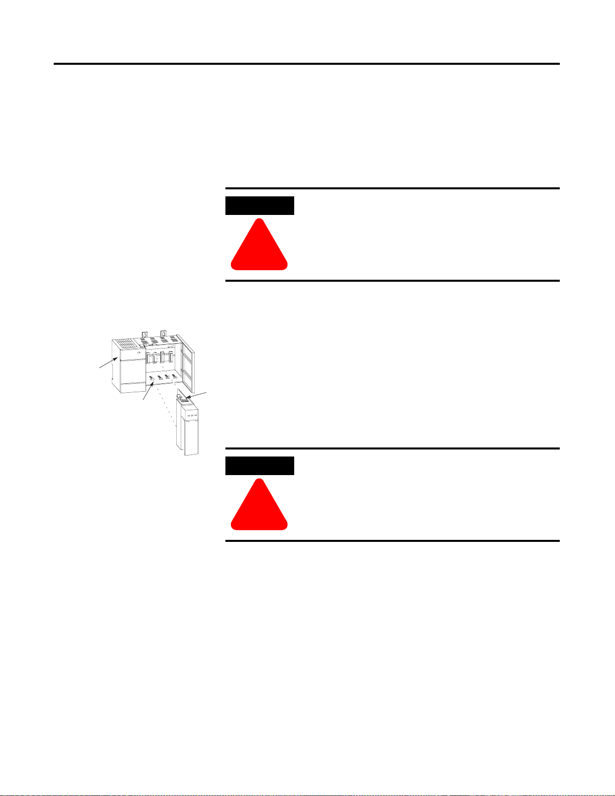
Installing the Adapter Module in the Chassis
Power
Supply
Card Guide
Once you’ve set the appropriate switch assemblies for your adapter module,
follow these procedures for installation.
Refer to the Industrial Controller Wiring and Grounding Guidelines, Publication
1770-4.1 for proper grounding and wiring methods to use when installing
your module.
ATTENTION
Remove system power before removing or installing your
module in the I/O chassis. Failure to observe this warning
could damage module circuitry and injure people.
!!!!
1. Remove power from the I/O chassis before inserting (or removing) the
module.
2. Align the circuit board with the chassis card guide in the left slot.
3. Slide the module into the chassis until the top and bottom latches are
Latch
latched. To remove the module, press the releases at the top and bottom
of the module and slide it out.
4. Press firmly and evenly to seat the module in its backplane connectors.
ATTENTION
!!!!
Do not force the module into the backplane connector. If
you cannot seat the module with firm pressure, check the
alignment. Forcing the module can damage the backplane
connector or the module.
Publication 1747-UM003 A-EN-P
Page 16
2-4 Installing Your ControlNet Adapter Module
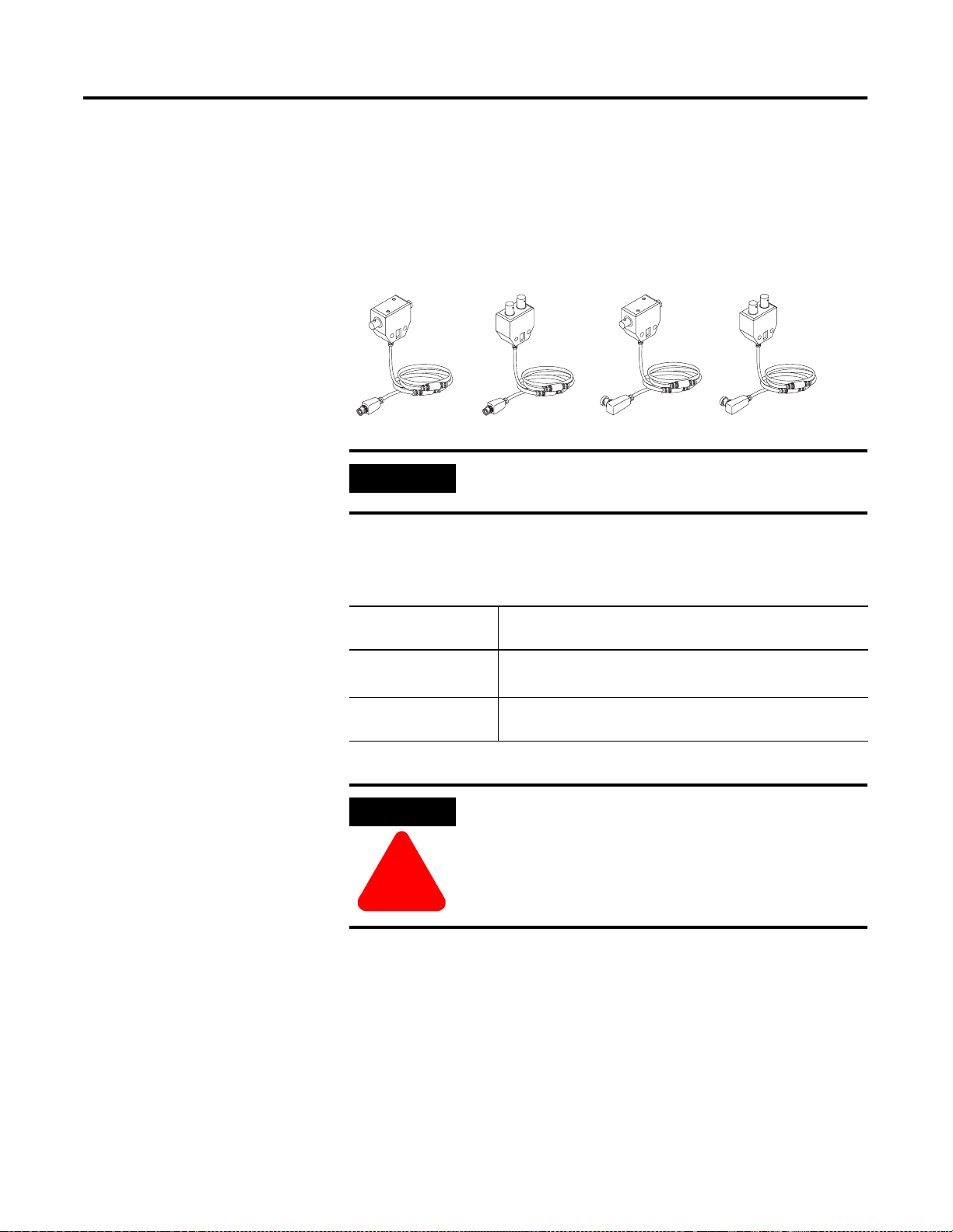
Connecting Your Adapter to the ControlNet Network
You connect your 1747-ACN15 or -ACNR15 adapter module to a
ControlNet network via taps. These taps are available:
Straight T-tap
1786-TPS 1786-TPYS
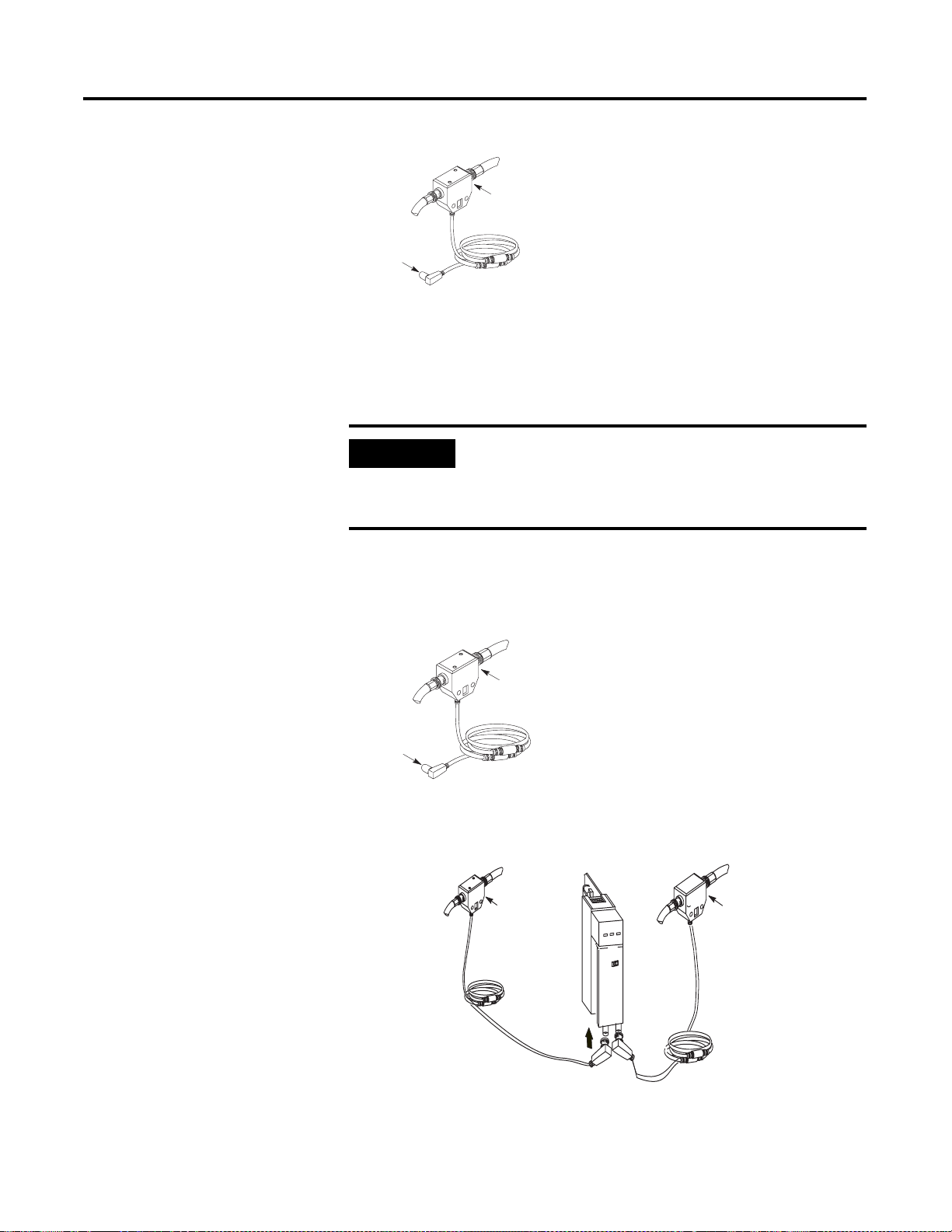
IMPORTANT
1. Remove the tap’s dust cap (located on the straight or right angle
connector).
If your node
supports:
Non-redundant media to the channel A connector on the 1747-ACN15 or
Redundant media • from trunkline A to channel A on the 1747-ACNR15
(1)
While both channels are active, Allen-Bradley recommends using channel A for non-redundant media.
Straight Y-tap
Taps contain passive electronics and must be purchased
from Allen-Bradley for the network to function properly.
Connect the tap’s straight or right angle connector:
1747-ACNR15 (channel B on the 1747-ACNR is not used)
• from trunkline B to channel B on the 1747-ACNR15
Right-angle T-tap Right-angle Y-tap
1786-TPR
1786-TPYR
(1)
Publication 1747-UM003A-EN-P
ATTENTION
!!!!
Do not allow any metal portions of the tap to contact any
conductive material. If you disconnect the tap from the
adapter, place the dust cap back on the straight or right
angle connector to prevent the connector from accidentally
contacting a metallic grounded surface.
Page 17
Installing Your ControlNet Adapter Module 2-5
segment 1
Tap
dust cap
2. Remove and discard the dust caps from the adapter BNC jacks.
3. Connect this tap’s straight or right angle connector to the BNC
connector on the adapter.
IMPORTANT
To prevent inadvertent reversal of the tap connections
(resulting in incorrect LED displays and troubleshooting),
check the tap drop cable for a label indicating the attached
segment before making your connection.
4. For redundant adapters (1747-ACNR15), remove (and save) the dust
cap located on the straight or right angle connector of the designated tap
on the second segment (segment 2).
segment 2
tap
dust cap
5. Connect this tap’s straight or right angle connector to the BNC
connector on the adapter.
segment 1
tap
segment 2
tap
After terminating your segments, connect the node to the network.
Publication 1747-UM003 A-EN-P
Page 18
2-6 Installing Your ControlNet Adapter Module
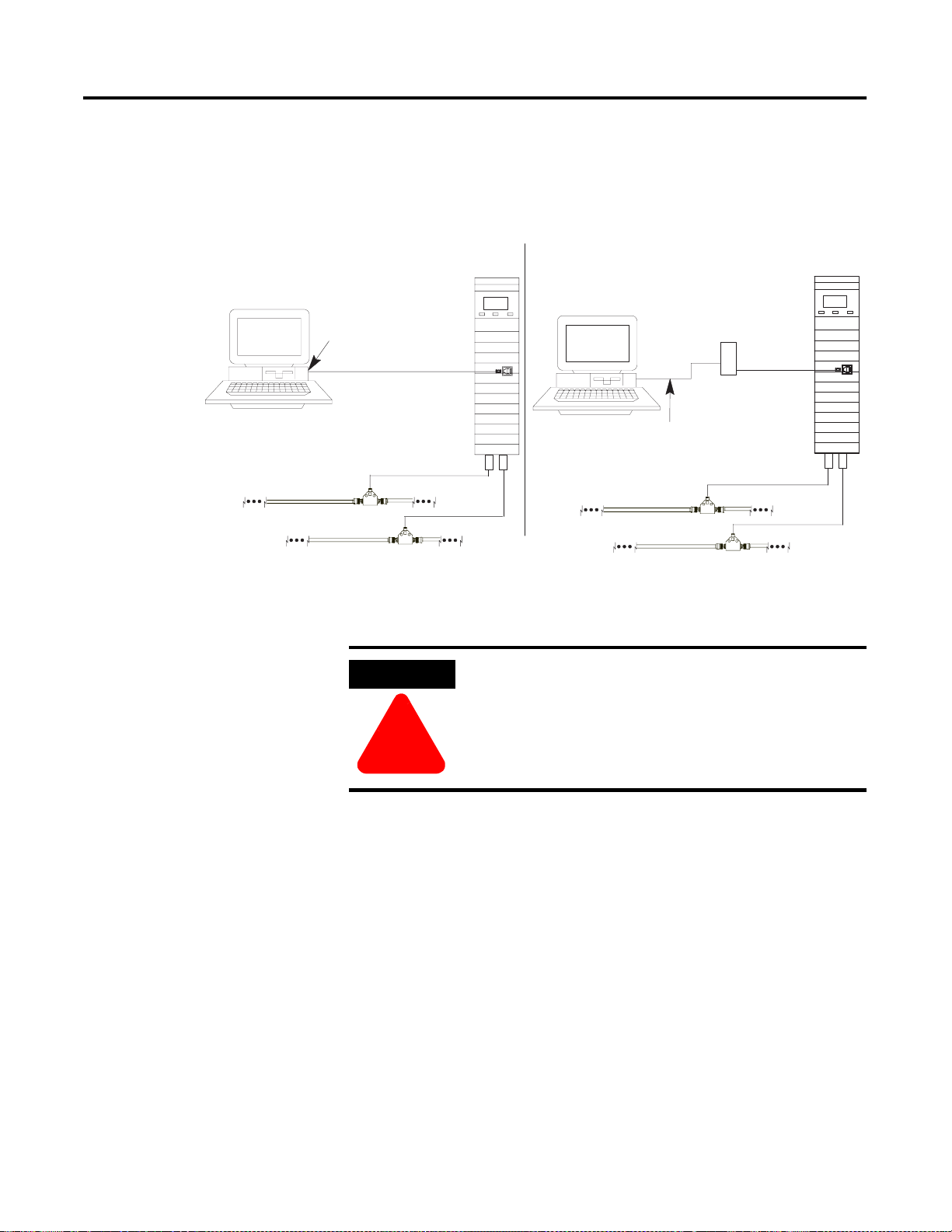
Connecting Programming Terminals to the Network via the NAP
Using 1784-KTC or -KTCx Communication Card and NAP
Programming Terminal
1784-KTC or
-KTCx
ControlNet network
You can connect programming terminals to the ControlNet network by
connecting to the network access port (NAP). Two methods are shown below.
Using 1770-KFC Communication Interface and NAP
Programming Terminal
1770-KFC
(1)
1786-CP
ControlNet
product
(1) The 1786-CP cable can be plugged into any ControlNet product’s NAP to provide
programming capability on the ControlNet network. A programming terminal connected
through this cable is counted as a node and must have a unique address.
Serial or Parallel
Connection
ControlNet Network
1786-CP
ControlNet
product
(1)
ATTENTION
!!!!
Use the 1786-CP cable when connecting a programming
terminal to the network through NAPs. Using a
commercially available RJ-style cable could result in
possible network failures.
Publication 1747-UM003A-EN-P
Page 19

Installing Your ControlNet Adapter Module 2-7
Powerup Sequence
There are three health indicators on the module. The LED on the right
(labeled “OK”) is the generic module health indicator. The LED in the middle
(labeled “A”) is the health indicator of cable A. On the 1747-ACNR15, the
LED on the left (labeled “B”) is the health indicator for cable B. In addition,
the alphanumeric display can display module status. The following describes
the normal power-up sequence for the adapter module. (Refer
to Troubleshooting With the Status Indicators and Status Display on page 5-1
and ControlNet Status Indicators on page 5-3 for explanation of the LED’s
and alphanumeric display.)
ADDRESS/STATUS
B
A
Status
Health Indicators
Channel A and B
OK
indicators
1. Apply power to the chassis - notice that all three health indicators should
be off and the status window indicates “POST” (Power On Self Test).
2. After “POST”, the status window displays the sequence “0000”, “1111”,
“2222”, through “9999”. During this time, the A and B LEDs are off
and the OK LED toggles between red and green; this happens so fast,
the OK LED appears amber.
3. The series and revision levels are then displayed in the status window. A
series A revision level B module would display “A/B”. During this time,
the A and B LEDs are off and the OK LED toggles between red and
green; this happens so fast, the OK LED appears amber.
4. After the operating system is loaded and initialized, the status window
and the LEDs indicate the status of the module and its connections to
the cable(s). If the module address is not zero and a valid ControlNet
connection is made to either channel A or B, the status window toggles
between “ACTV” (Active) and the module node address (“A#02”, node
address number 2). If there are no active connectors, the status window
displays “IDLE”.
5. If there is a hardware problem of any kind, the health LED turns red and
the status window toggles between “FATL” and up to four alphanumeric
characters. The “FATL” indicates that there was a fatal error and the
characters indicate what the error is.
For detailed information on planning and installing your ControlNet system,
refer to Related Publication on page P-1.
Publication 1747-UM003 A-EN-P
Page 20

2-8 Installing Your ControlNet Adapter Module
Publication 1747-UM003A-EN-P
Page 21

Chapter
3
Planning to Use Your ControlNet Adapter
Module
Chapter Objectives
Compatible 1746 and 1747 I/O Modules
This chapter explains how the adapter operates on ControlNet and
provides information to assist in configuring your system. This includes:
• compatible 1746 and 1747 I/O modules
• overview of adapter operation
• software requirements
• rack and module connections
• optimizing SLC ControlNet Adapter connections
• module keying
• output operation during Fault and Idle modes
• understanding ControlNet I/O
• scheduled Data-Transfer connections on a ControlNet network
The majority of 1746 and 1747 discrete, analo g and specialty modules
are compatible with the 1747-ACN15 and 1747-ACNR15 adapters.
Exceptions include any modules that require G file configuration. These
include:
• 1747-SN Remote I/O Scanner module
• 1747-BSN Back-Up Remote I/O Scanner module
• 1746-QV Open Loop Velocity Control module
• 1203-SM1 Scanport module (Class 4 operation) (This module is
compatible when configured for class 1 operation.)
• 1747-SCNR ControlNet Scanner module (G files not required,
however, this module is not supported by the 1747-ACN15/
ACNR15)
A small number of 1746 modules are currently not supported by the
adapter due to lack of an EDS (electronic data sheet) file. These
modules will be supported once EDS development is completed. A
complete list of compatible 1746 and 1747 modules can be found on the
Allen-Bradley Technical Support Knowledge Base at:
http://www.ab.com/support/kbhome.html.
Page 22

3-2 Planning to Use Your ControlNet Adapter Module
Overview of Adapter Operation
Connections are established between a scanner and an adapter to exchange
input and output data on the network. Status information is transferred along
with the I/O data and status.
1747-ACN15/ACNR15 adapters support connections to individual modules
and rack connections to a group of modules. The adapters support multiple
rack and group connections to the same modules, as long as only one scanner
controls any module’s outputs. Up to 64 connections per adapter are possible
with 240 words (max) supported per connection. An adapter can control up to
30 slots of 1746 I/O (3 chassis max). The input data attributes correspond
directly to the read area of the I/O module’s data table image. The output
attributes correspond directly to the write area of the I/O module’s data table
image.
RSNetWorx is the software tool that is used to schedule network bandwidth
for all scheduled traffic originators that reside on a ControlNet network
segment. RSLinx is the communication software tool used by RSNetWorx to
access the ControlNet network. A 1784-KTCX15 PC card or 1784-PCC
ControlNet card can be used as the hardware interface to the network.
Software Requirements
RSNetWorx for ControlNet version 2.23.00 or greater is required to configure
the 1747-ACN15/ACNR15 adapters. If you only have RSNetWorx for
ControlNet version 2.22.18, it is necessary to add the Service Pack in order to
configure connections with the 1747-ACNR15 adapter. To add the Service
Pack, follow the steps below.
1. Access the Rockwell Software support page at:
http://www.software.rockwell.com/support
2. Click Downloads form the list of choices in the left column.
3. Locate section 2, “Choose a Product”.
4. Click the down arrow and select RSNetWorx from the drop down list.
5. In section 4, click Search.
6. Click Service Pack 1, or click a later version for the Service Pack if it is
not the only Service Pack available.
7. After the download is completed, close all programs and run the
installation of the software. Follow the screen prompts to guide you
through the installation process. If you experience problems performing
the install, contact Rockwell Software Technical Support.
Publication 1747-UM003A-EN-P
When Service Pack 1 is installed, the version of RSNetWorx for ControlNet is
2.23.00 or greater.
Page 23
Planning to Use Your ControlNet Adapter Module 3-3
Rack and Module Connections
There are two types of scheduled connections supported by the 1747-ACN15,
-ACNR15: the rack connection and the individual module connection.
Rack Connections
For each rack connection, RSNetWorx maps 8, 16, or 32 input and output bits
per slot.
Operation Description
8-bit Rack
Connections
16-bit Rack
Connections
32-bit Rack
Connections
Performed in a deterministic and repeatable manner. This
connection allows a memory and ControlNet bandwidth
efficient way to connect to a rack of 8-bit modules
Performed in a deterministic and repeatable manner. This
connection allows a memory and ControlNet bandwidth
efficient way to connect to a rack of 16-bit modules.
Performed in a deterministic and repeatable manner. This
connection allows a memory and ControlNet bandwidth
efficient way to connect to a rack of 32-bit modules.
The rack connection is used to define a single connection for the discrete
I/O in the SLC backplane. Multiple rack connections, with limitations, are
supported in the SLC adapter. For example, a connection originator might
specify an 8-bit, 16-bit, or 32-bit data size.
IMPORTANT
RSNetWorx allows more than one exclusive owner rack
connection type to be configured to a 1747 adapter (e.g.
8-bit exclusive owner, 16-bit exclusive owner, and 32-bit
exclusive owner), however onl y one exclusive owner rack
connection can be operational at one time. It is
recommended that only one exclusive owner rack
connection type be configured to the adapter to avoid
contention between multiple connections.
IMPORTANT
If a rack connection type is changed to a smaller bit
configuration e.g. 32-bit to 16-bit, or 16-bit to 8-bit, the
unused bits for the new connection are reset to zero.
Publication 1747-UM003 A-EN-P
Page 24

3-4 Planning to Use Your ControlNet Adapter Module
Module Connections
Module connections are performed in a deterministic and repeatable manner.
This connection allows a memory and ControlNet bandwidth efficient way to
connect to an individual module with more I/O data than could be attempted
in the above rack connections, or to transfer M0/M1 file data.
Each rack and module connection can be configured with the following
connection types:
1. Exclusive Owner - specifies an independent connection where a single
device controls the output states in the target device. If you have an
existing Exclusive Owner connection to a target device, you cannot
specify another Exclusive Owner or Redundant connection to that same
target device.
2. Input Only - specifies an independent connection where a device
receives inputs fro m the target device and sends c onfiguration data to
the target device. An Input Only connection does not send outp uts; it
only receives inputs. You can specify multiple Input Only connect ions
to the target device from different originators.
3. Listen Only - specifies a dependent connection where a device receives
inputs from the target device, but does not send configuration data with
the target device. A Listen Only connection only functions properly
when another non-Listen Only connection exists to the same target
device. A Listen Only connection does not send outputs; it only receives
inputs. You can specify multiple Listen Only connections to the target
device from different originators.
NOTE
All Listen Only connections are terminated when all
associated independent connections are terminated.
Optimizing SLC ControlNet Adapter Rack Connections
Consider the following example placement of ControlNet devices when you
want to optimize your SLC ControlNet adapter connection:
Node Slot Device
1 1747-SCNR
2 0 1747-ACNR15
1 1746-IB16
2 1746-IB16
3 1746-OB16
4 1746-OB16
5 1746-NIO4I
6 1746-HSCE
Publication 1747-UM003A-EN-P
Page 25

Planning to Use Your ControlNet Adapter Module 3-5
If we change the default number of words for the input and output values (to 4
and 4) when inserting the connection to the 1747-ACNR15 adapter, Node 2
will produce 4 input words over ControlNet and Node 1 will consume and
place those words at addresses I:e.1-4, where the slot 1 inp uts corresp ond to
I:e.3 and the slot 2 inputs correspond to I:e.4. In addition, Node 1 will produce
4 output words over ControlNet originating from addresses O:e.1-4 and Node
2 will consume them. A total of 8 words (4 input and 4 output) are transmitted
on ControlNet.
NOTE
To optimize ControlNet network bandwidth, place the
devices in the following order (left to right on the chassis):
• 1747-ACNR15 adapter
• Discrete input modules
• Discrete output modules
• Any intelligent and/or analog I/O modules that you want
to establish individual module connections to
Consider the following:
• The 1747-SCNR has 31 input words and 31 output words available for
rack connections to 1747-ACNR15 adapters.
• Each 1747-ACNR15 adapter requires 2 input words for status in addition
to the input words assigned to the slots.
• Adjust the rack connection size to match the maximum density I/O
module:
– Discrete 8-bit Exclusive Owner for 4 and 8-point modules
– Discrete 16-bit Exclusive Owner for 16-point modules
– Discrete 32-bit Exclusive Owner for 32-point modules.
Module Keying
Missing or misplaced modules are detected if the module in question is
configured with RSNetWorx as an individual module connection and
“compatible module” is selected for electronic keying. If a module connection
is attempted to a module which is a missing or misplaced module, the
connection will fail. The green OK LED on the initiating scanner will flash
and the module will display “I/O” with a partially filled bar indicating all
connections are not established, as shown below.
I/O
Publication 1747-UM003 A-EN-P
Page 26

3-6 Planning to Use Your ControlNet Adapter Module
NOTE
The electronic keying option offered by RSNetWorx for
rack connections applies to the 1747-ACN15 and
-ACNR15 modules only.
Missing or misplaced modules are not detected if the
module in question is configured within a rack connection.
Critical I/O modules that need to be detected when
missing or mispla ced must be configured with indiv idual
module connections.
Output Operation During Fault and Idle Modes
RSNetworx allows configuration to characterize each module connection
activity during certain operational states.
During idle mode and fault modes, outputs are configured for one of the
following operation states:
Output Action
Reset outputs to off
Hold last state
Write Safe State data to outputs
Understanding ControlNet I/O
The ControlNet system is designed to:
• provide high-speed, repeatable, deterministic I/O transmission
• allow control and message information to co-exist on the same physical
media
• make sure that I/O data transfers are not affected by
– programming-terminal message activity
– inter-processor message activity on the network
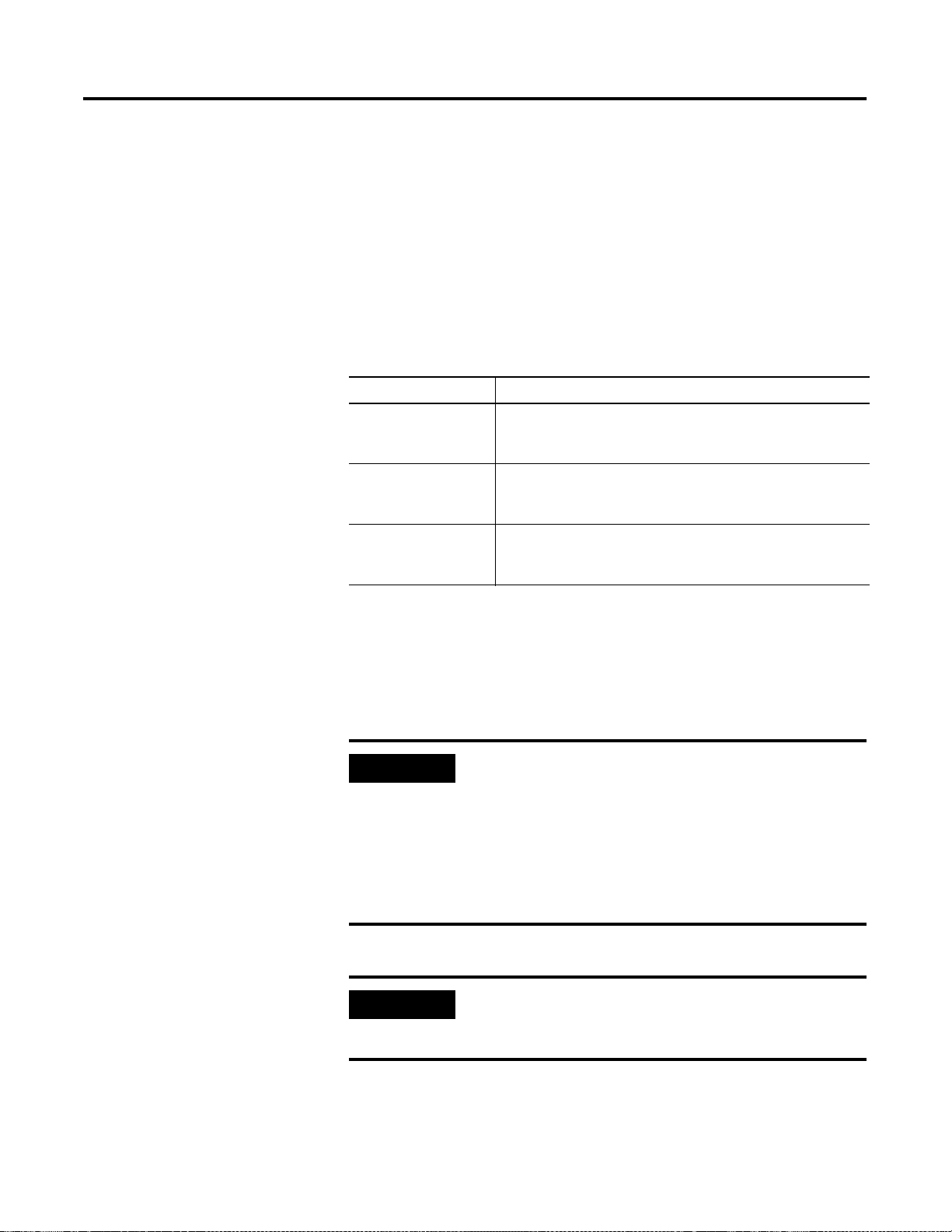
Scheduled Data-Transfer Connections on a ControlNet Network
Scheduled data transfer on a ControlNet processor:
• is continuous
• is asynchronous to the ladder-logic program scan
• occurs at the actual rate displayed in the Actual Packet Interval field on the
RSNetWorx ControlNet I/O mapping (monitor) screen
Publication 1747-UM003A-EN-P
Page 27
Planning to Use Your ControlNet Adapter Module 3-7
PrivateMemory
Buffers
Scheduled Data Transfers
Scheduled Data Transfer Program Scan
Data Update
DataTab le
Files
Housekeeping
Logic Scan
The ControlNet system places your scheduled transfers in the first part of each
Network Update Interval. Time is automatically reserved for network
maintenance. Unscheduled transfers are performed during the time remaining
in the interval.
You reserve a
specific amount
of time for all
scheduled
operations.
The system
reserves time for
network
maintenance
Any time remaining is used for
unscheduled operations
. . .. . .
Your application and your configuration-number of nodes, application
program, NUT (Network Update Time), amount of scheduled bandwidth
used, etc. determine how much time there is for unscheduled messaging.
IMPORTANT
The ControlNet network reserves time for at least one
maximum-sized unscheduled transfer per update interval.
Depending on how much time there is for unscheduled
messaging, every node may not have a chance to send
unscheduled data every update interval.
Publication 1747-UM003 A-EN-P
Page 28

3-8 Planning to Use Your ControlNet Adapter Module
Publication 1747-UM003A-EN-P
Page 29

Chapter
Application Examples
Table 4.A Table of Contents
Example Number Title Page
1 1747-SCNR ControlNet Scanner Controlling Discrete I/O on
ControlNet via a 1747-ACN15 ControlNet Adapter Using a
Rack Connection
2 1747-SCNR ControlNet Scanner Controlling Discrete and
Analog I/O on ControlNet via a 1747-ACN15 ControlNet
Adapter Using a Rack Connection
3 1747-SCNR ControlNet Scanner Controlling Discrete and
Analog I/O on ControlNet via a 1747-ACN15 ControlNet
Adapter Using Rack and Module Connections
4 1747-SCNR ControlNet Scanner Controlling Discrete I/O and
Serial Data with a 1746-BAS Module on ControlNet via a
1747-ACN15 ControlNet Adapter Using Rack and Module
Connections
5 1747-SCNR ControlNet Scanner Controlling Discrete I/O and
Specialty Modules Requiring M0 File Configuration on
ControlNet via a 1747-ACN15 ControlNet Adapter Using Rack
and Module Connections
4-2
4-11
4-21
4-31
4-46
4
1 Publication 1747-UM003 A-EN-P
Page 30
4-2 Application Examples
Example 1
1747-SCNR ControlNet Scanner Controlling Discrete I/O on ControlNet via a
1747-ACN15 ControlNet Adapter Using a Rack Connection
This example is organized into the following sections:
• Hardware Setup
• Configuring The ControlNet Network with RSNetWorx™ for
ControlNet, Revision 2.23.02 or later
• Create a Ladder Logic Program
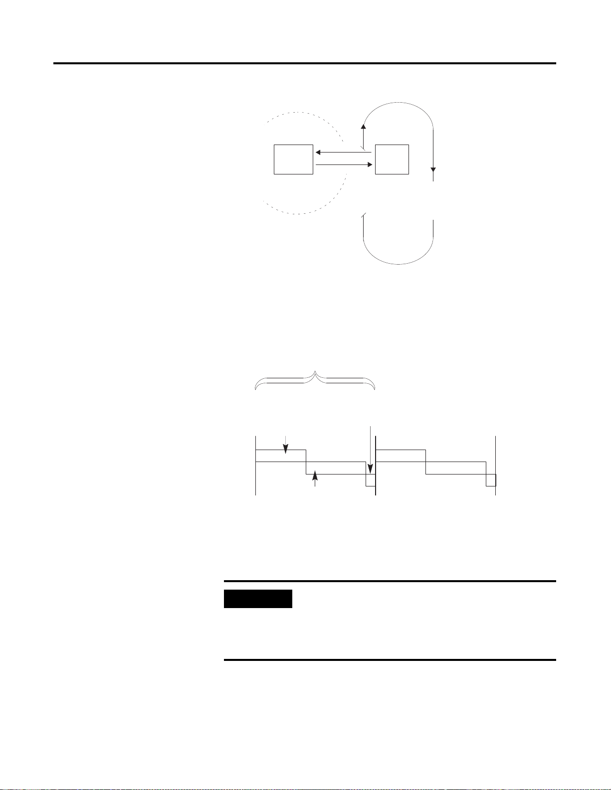
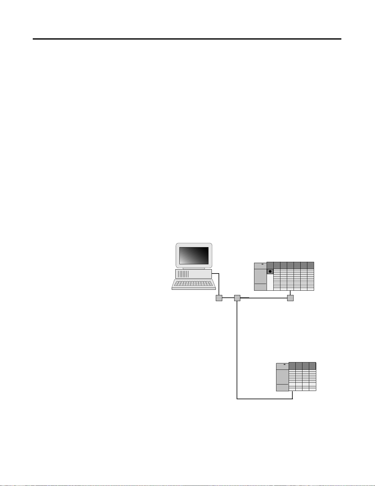
Hardware Setup
The following hardware setup is referenced throughout this example.
Computer with:
• RSLogix 500 Software
• RSLinx Software
• RSNetWorx Software for ControlNet
• 1784-KTCX15 ControlNet PC Card
tap
tap
ControlNet
SLC 5/04
tap
1747-SCNR
1747-ACN15
1746-IA16
1746-OB16
1746-IV16
Publication 1747-UM003A-EN-P
Page 31

Application Examples 4-3
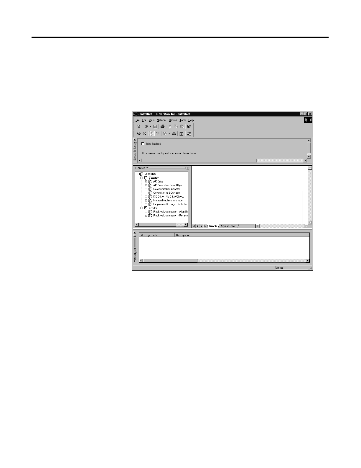
Configuring The ControlNet Network with RSNetWorx™ for ControlNet
Start RSNetWorx for ControlNet by double clicking on its icon. The following
screen appears:
At this point, you could configure your ControlNet network off-line and then
download it to the network. This example will, instead, go on-line and
configure the network. Therefore, click on the on-line icon or click on the
Network pull-down menu and select On-line.
A Browse for Network window appears, where you must select the
communication path previously configured in RSLinx for communicating
with your ControlNet network. In this example, a KTC ControlNet PC card
was used. Click on the KTCX15 card to select it and then click OK.
Publication 1747-UM003 A-EN-P
Page 32

4-4 Application Examples
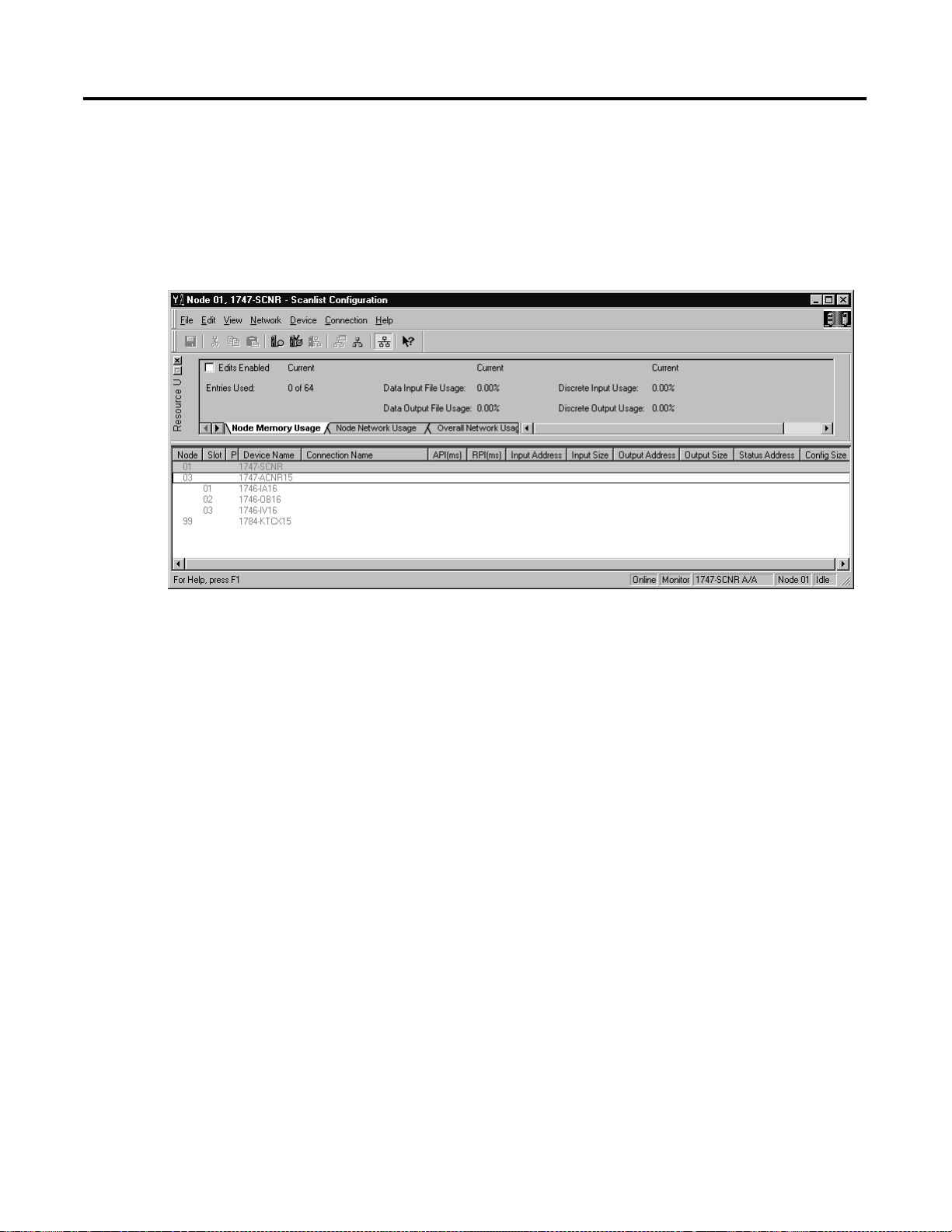
The software attempts to communicate with all possible node numbers on the
network, from 1 to 99. Click on the Edits Enabled box to allow changes to be
made. For this example, the on-line network screen should look like the
following, where node 99 is the programming terminal.
Node 1 is the 1747-SCNR and node 3 is the 1747-ACN15. The
1747-ACN15 resides in slot 0 of its chassis, while slot 1 contains a 1746-IA16,
slot 2 contains a 1746-OB16, and slot 3 contains a 1746-IV16. For this
example, a single 16-bit rack connection will be configured to read/write the
three discrete I/O modules.
Before creating the connection, verify the chassis configuration for the
1747-ACN15 chassis. To do this, right click on the 1747-ACN15, then choose
Edit Chassis. Verify that the chassis configuration is as follows:
slot 0: 1747-ACNR15
slot 1: 1746-IA16
slot 2: 1746-OB16
slot 3: 1746-IV16
If the chassis is not already configured, manually configure it by dragging the
appropriate modules from the list on the right to the proper slot on the left of
the chassis configuration screen. When on-line, the software reads the module
types for you. When this is complete, click Apply, then OK.
Publication 1747-UM003A-EN-P
Page 33
Application Examples 4-5
Configuring a Chassis Connection
You are now ready to configure the necessary ControlNet connection to read/
write data from the SLC processor to the discrete I/O modules. Right click on
the 1747-SCNR and choose Scanlist Configuration. (If you are prompted to
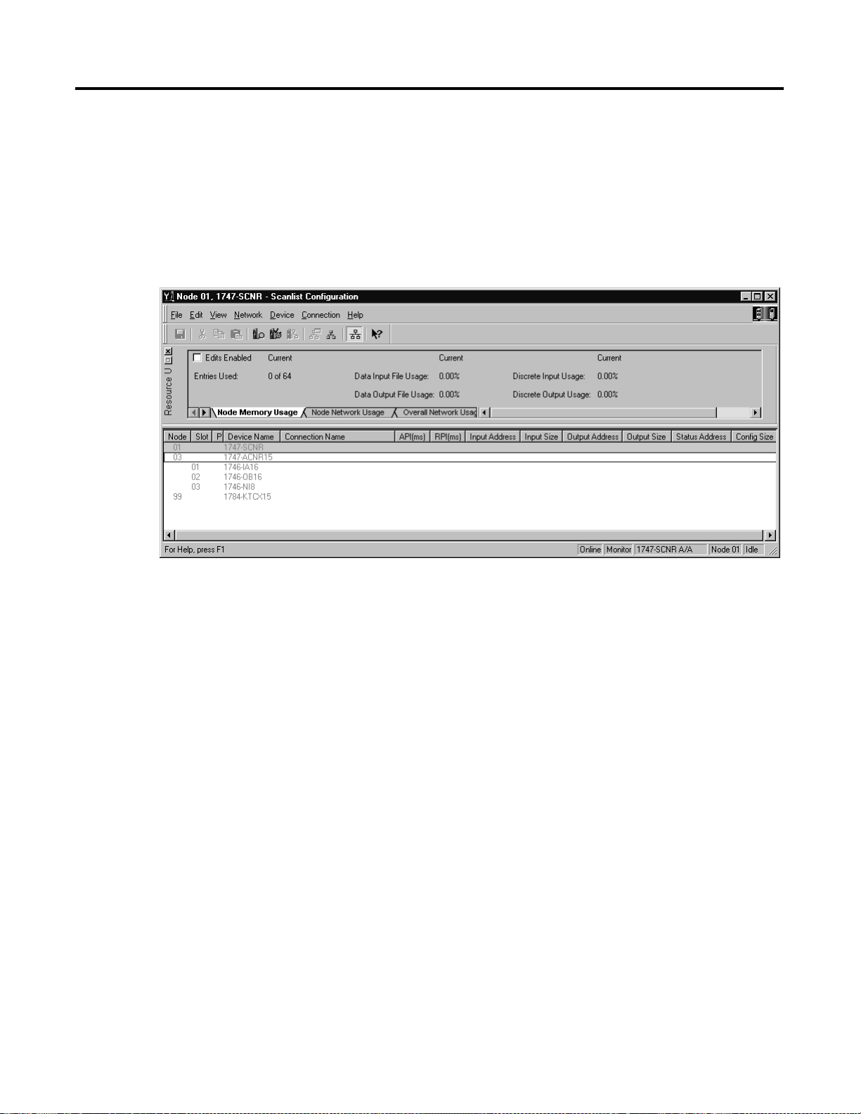
enter the edit mode, click YES.) The following screen appears:
Publication 1747-UM003 A-EN-P
Page 34

4-6 Application Examples
The 1747-SCNR and 1747-ACN15 are shown as nodes 1 and 3 respectively.
Under the 1747-ACN15, the 3 I/O modules in slots 1 through 3 of the
1747-ACN15 chassis are listed. In order to establish a 16-bit rack connection
to the 1747-ACN15 chassis, right click on the 1747-ACN15 and choose Insert
Connection. The following window opens:
Publication 1747-UM003A-EN-P
Note that addresses in the Connection Properties screen above are already filled
in. To have RSNetWorx choose the next available valid I/O or M-file addresses
for all connections, click on the Auto Address Preferences button. Next, click on
the box next to Enable Automatic Addressing on Insert so a check mark appears
in the box. Then click OK. Auto Addressing enabled is the default.
IMPORTANT
RSNetWorx allows more than one exclusive owner rack
connection type to be configured to a 1747 adapter (e.g.
8-bit exclusive owner, 16-bit exclusive owner, and 32-bit
exclusive owner), however only one exclusive owner rack
connection can be operational at one time. It is
recommended that only one exclusive owner rack
connection type be configured to the adapter to avoid
contention between multiple connections.
Page 35

Application Examples 4-7
IMPORTANT
If a rack connection type is changed to a smaller bit
configuration e.g. 32-bit to 16-bit, or 16-bit to 8-bit, the
unused bits for the new connection remains in their
previously programmed states for program mode or lost
communications e.g. last state, safe state, reset off.
The Connection Name, by default, is Discrete 16-Bit Exclusive Owner and this is
the 16-bit rack connection you want. The first available I/O addresses are I:3.1
and O:3.1, where the 1747-SCNR is in slot 3 of the processor chassis. The first
available starting I/O addresses have been placed into the Input Address and
Output Address fields, because automatic addressing was previously selected in
the Auto Address Preference screen. Words I:3.0 and O:3.0 contain status and
control data and are not used for I/O data.
Note that the input data from the 1746-IA16 is found in the processor’s input
image word I:3.3 and the output data written to the 1746-OB16 module is
from the processor’s output image word O:3.2. The input data from the
1746-IV16 is in the processor’s input image word I:3.5.
NOTE
There is a 2-word offset for input data for rack connections.
Therefore, for this example, the input data for the input
module in slot 1 of the remote 1747-ACN15 chassis is
written to I:3.3 in the SLC processor’s input image. The
input module in slot 3 is written to I:3.5.
The starting input address configured in RSNetWorx for
this rack connection was I:3.1, but I:3.1 and I:3.2 are used
for rack slot status information. Note the resulting input
size of 5 shown in the Connection Properties screen.
Therefore, the actual input data begins after the 2 words of
status information. I:3.4 is not used in this example because
an output module resides in slot 2.
Also, note that there is no offset for the outputs in a rack
connection. O:3.2 is the output image word written to the
output module located in slot 2 of the 1747-ACN15
chassis. O:3.1 is also not used in this example because an
input card is in slot 1.
The Status Address field must also be filled in. This field supplies Connection
Status information to the processor for each unique connection. The starting
bit address for this field must be an even number because two consecutive bits
are used as status for each connection. The even numbered bit indicates
whether the connection is open or closed. The odd numbered bit indicates
whether the connection is in normal operation or Idle mode. In this example,
the starting address chosen is the first available bit pair, M1:3.600/00.
Publication 1747-UM003 A-EN-P
Page 36

4-8 Application Examples
You have successfully configured a rack connection to the remote chassis to
communicate with the discrete I/O modules. At this point, you may also
configure the state of the outputs in the remote ControlNet chassis when the
controlling processor is placed into the Program mode or if communications
are lost to the remote chassis. This is optional. The default is to turn all outputs
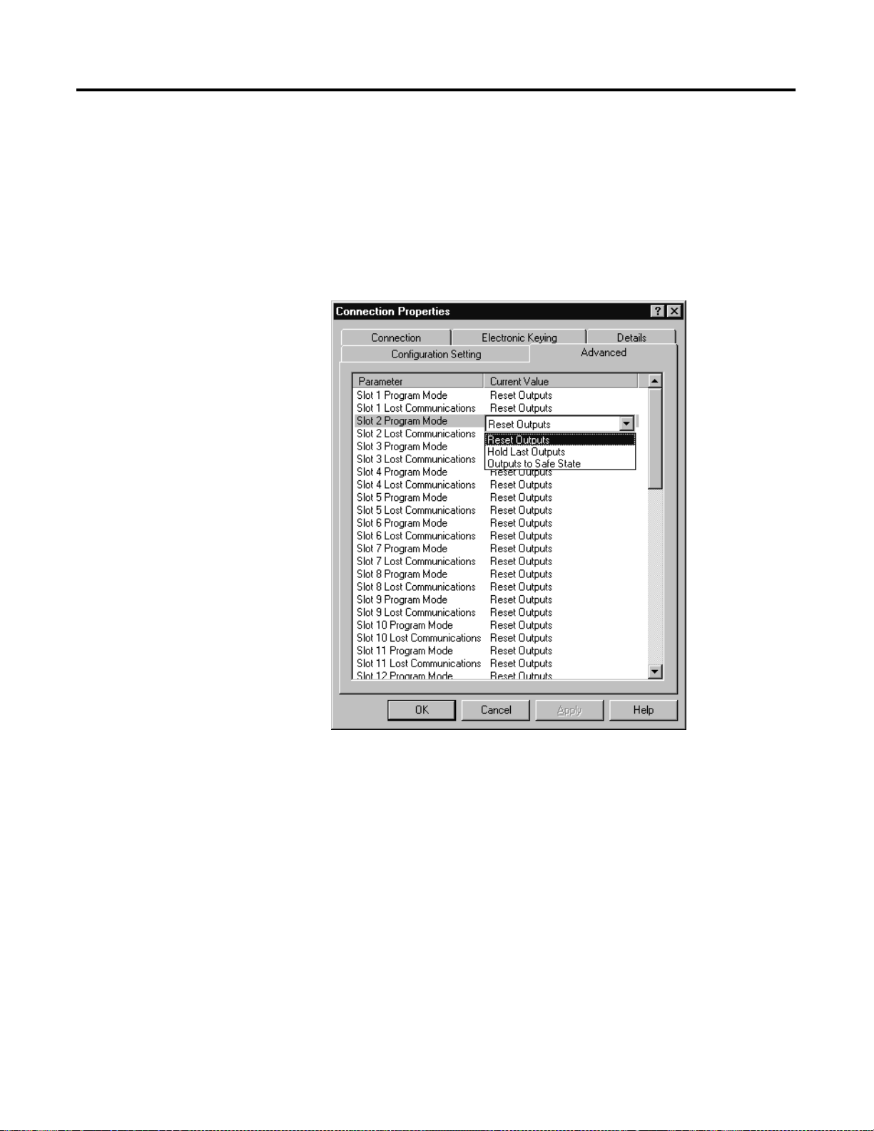
off when one of the two conditions occur. To select other options, click on the
Advanced tab in the Connection Properties window. The following window
appears:
Publication 1747-UM003A-EN-P
By default, outputs in all slots in the remote chassis are reset if the processor is
placed into the Program mode or if communications are lost for any reason.
Two other choices are offered when one of the two conditions occur. They are:
• Hold Last Outputs
• Outputs to Safe State
Hold Last Outputs holds outputs in their last state if one of the two conditions
occur. Safe State allows you to choose the exact state of each output. If Safe
State is selected, you must click on the Configuration Settings tab and enter your
Safe State data for each output word in decimal. Then, if the SLC processor is
Page 37

Application Examples 4-9
placed in the Program mode or if communications are lost to the ACN15
adapter, the outputs revert to the Safe State data you entered for each output
word.
Click Apply, then OK to return to the ScanList Configuration window which
should look like the following:
You have now successfully configured your rack connection to read/write data
between the SLC processor and the remote ControlNet chassis. All that
remains is to Save this configuration to the network keeper which, in this case,
is the 1747-SCNR.
Click on the Save icon or choose the File pull-down menu and select Save. You
are prompted to Optimize and re-write schedule for all connections. Click OK,
then click YES to the subsequent warning message. Your network
configuration information is then written to the network keeper and scanner
devices.
The display on the front of your 1747-SCNR should show a Full Glass next to
I/O. This indicates that all configured connections have been successfully
downloaded to the scanner. In addition, the A and OK LEDs should be solid
green and the B LED should be off, unless you are using the redundant media
option, which is not being used in this example. The 1747-ACN15 should be
displaying that it is active (ACTV) and its LEDs should be solid green for A
and OK.
Publication 1747-UM003 A-EN-P
Page 38

4-10 Application Examples
Create a Ladder Logic Program
The final step is to write a ladder program for the SLC processor, including
configuring the 1747-SCNR for slot 3 of the processor’s chassis. After
downloading the program to your processor, place it into the RUN mode. Your
program should now be able to read data from the 1746-IA16 in word I:3.3,
write to the 1746-OB16 in word O:3.2 and read data from the 1746-IV16 in
word I:3.5.
Note that your ladder program should also contain an unconditional rung with
an OTE instruction addressed to the SCNR scanner’s RUN/IDLE bit, O:3.0/
10 for this example. When the SLC processor is placed into the RUN mode,
this rung sets the SCNR scanner’s RUN/IDLE bit and places the scanner into
the RUN mode as well. The scanner begins executing the configured
connections when the RUN/IDLE bit is set.
Publication 1747-UM003A-EN-P
Page 39

Application Examples 4-11
Example 2
1747-SCNR ControlNet Scanner Controlling Discrete and Analog I/O on
ControlNet via a 1747-ACN15 ControlNet Adapter Using a Rack Connection
This example is organized into the following sections:
• Hardware Setup
• Configuring The ControlNet Network with RSNetWorx™ for
ControlNet
• Create a Ladder Program
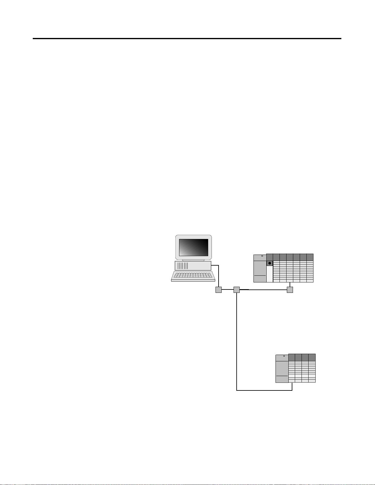
Hardware Setup
The following hardware setup is referenced throughout this example.
Computer with:
• RSLogix 500 Software
• RSLinx Software
• RSNetWorx Software for ControlNet
• 1784-KTCX15 ControlNet PC Card
tap
tap
ControlNet
SLC 5/04
tap
1747-SCNR
1747-ACN15
1746-IA16
1746-OB16
1746-NIO4V
Publication 1747-UM003 A-EN-P
Page 40

4-12 Application Examples
Configuring The ControlNet Network with RSNetWorx™ for ControlNet
Start RSNetWorx for ControlNet by double clicking on its icon. The following
screen appears:
Publication 1747-UM003A-EN-P
At this point, you could configure your ControlNet network off-line and then
download it to the network. This example, instead, goes on-line and configure
the network. Therefore, click on the on-line icon or click on the Network
pull-down menu and select On-line.
A Browse for Network window appears, where you must select the
communication path previously configured in RSLinx for communicating
with your ControlNet network. In this example, a 1784-KTCX15 ControlNet
PC card was used. Click on the KTC card to select it and then click OK.
Page 41

Application Examples 4-13
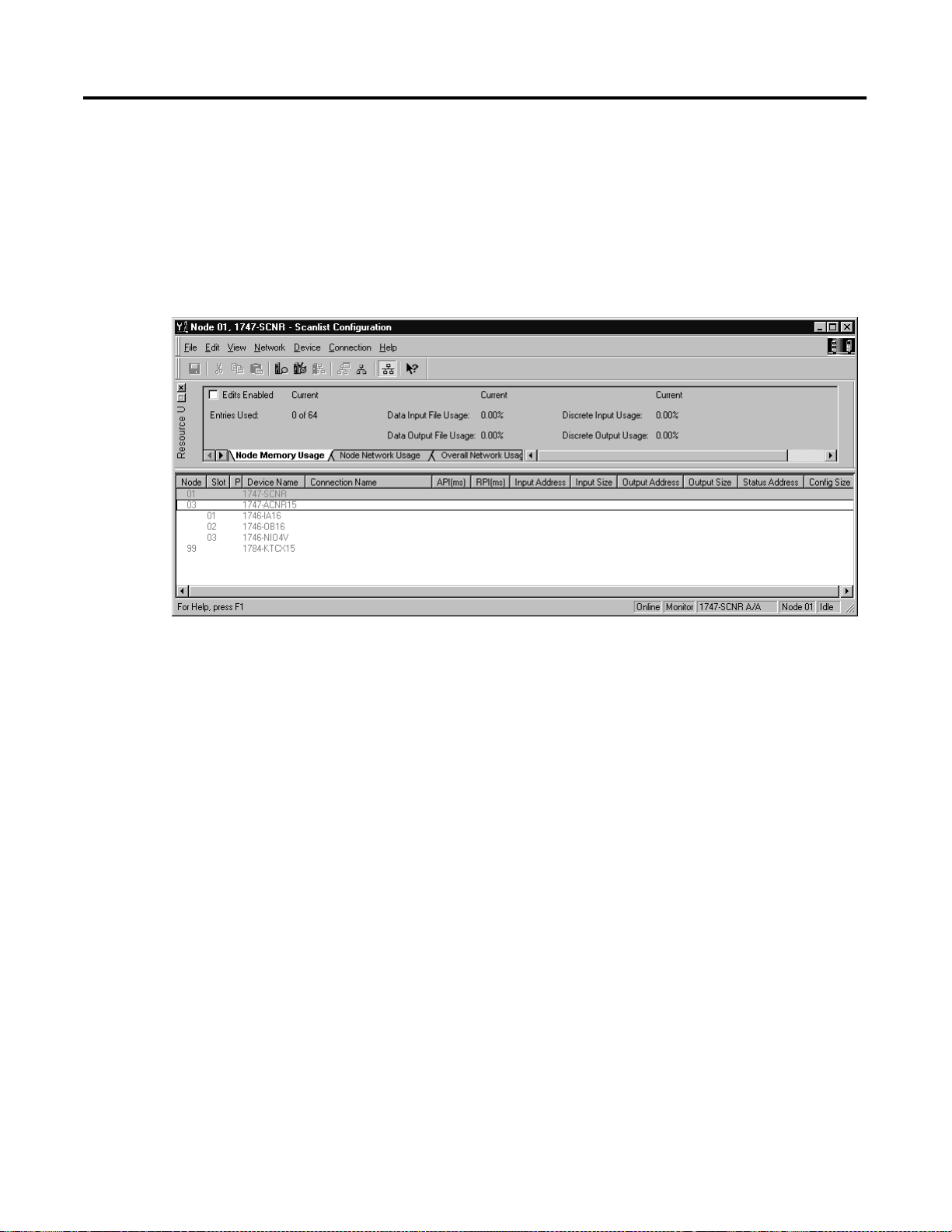
The software attempts to communicate with all possible node numbers on the
network, from 1 to 99. Click the Edits Enabled box to allow changes to be
made. For this example, the on-line network screen should look like the
following, where node 99 is the programming terminal.
Node 1 is the 1747-SCNR and node 3 is the 1747-ACN15. The
1747-ACN15 resides in slot 0 of its chassis, while slot 1 contains a 1746-IA16,
slot 2 contains a 1746-OB16, and slot 3 contains a 1746-NIO4V. For this
example, a single 32-bit rack controller is configured to read/write the three I/
O modules.
Before creating the connection, verify the chassis configuration for the
1747-ACN15 chassis. To do this, right click on the 1747-ACN15, then choose
Edit Chassis. Verify that the chassis configuration is as follows:
slot 0: 1747-ACNR15
slot 1: 1746-IA16
slot 2: 1746-OB16
slot 3: 1746-NIO4V
If the chassis is not already configured, manually configure it by dragging the
appropriate modules from the list on the right to the proper slot on the left of
the chassis configuration screen. When on-line, the software reads the module
types for you. When this is complete, click Apply, then OK.
Publication 1747-UM003 A-EN-P
Page 42
4-14 Application Examples
Configuring a Rack Connection
You are now ready to configure the necessary ControlNet connection to read/
write data from the SLC processor to the discrete I/O modules and to the
1746-NIO4V analog module. Right click on the 1747-SCNR and choose
Scanlist Configuration. (If you are prompted to enter the edit mode, click YES.)
The following screen appears:
Publication 1747-UM003A-EN-P
Page 43

Application Examples 4-15
The 1747-SCNR and 1747-ACN15 are shown as nodes 1 and 3 respectively.
Under the 1747-ACN15, the 3 I/O modules in slots 1 through 3 of the
1747-ACN15 chassis are listed. We specify a 32-bit rack connection so that the
two words of analog input and two words of analog output data from the
1746-NIO4V module can be transferred via the rack connection. In order to
establish a 32-bit rack connection to the 1747-ACN15 chassis, right click on
the 1747-ACN15 and choose Insert Connection. The following window opens:
Note that addresses in the Connection Properties screen above are already filled
in. To have RSNetWorx choose the next available valid I/O or M-file addresses
for all connections, click on the Auto Address Preferences button. Next, click on
the box next to Enable Automatic Addressing on Insert so a check mark appears
in the box. Then click OK. Automatic Addressing enabled is the default.
Publication 1747-UM003 A-EN-P
Page 44

4-16 Application Examples
IMPORTANT
RSNetWorx allows more than one exclusive owner rack
connection type to be configured to a 1747 adapter (e.g.
8-bit exclusive owner, 16-bit exclusive owner, and 32-bit
exclusive owner), however only one exclusive owner rack
connection can be operational at one time. It is
recommended that only one exclusive owner rack
connection type be configured to the adapter to avoid
contention between multiple connections.
IMPORTANT
If a rack connection type is changed to a smaller bit
configuration e.g. 32-bit to 16-bit, or 16-bit to 8-bit, the
unused bits for the new connection remains in their
previously programmed states for program mode or lost
communications e.g. last state, safe state, reset off.
The Connection Name, by default, is Discrete 16-Bit Exclusive Owner. Change
this to Discrete 32-bit Exclusive Owner. The first available I/O addresses are
I:3.1 and O:3.1, where the 1747-SCNR is in slot 3 of the processor chassis.
The first available starting I/O addresses have been placed into the Input
Address and Output Address fields, because automatic addressing was previously
selected in the Auto Address Preference screen. Words I:3.0 and O:3.0 are used
for status and control data.
Note that the input data from the 1746-IA16 is found in the processor’s input
image word I:3.3 and the output data written to the 1746-OB16 module is
from the processor’s output image word O:3.3. The 1746-NIO4V input data
is in I:3.7 and I:3.8, and the output data is in O:3.5 and O:3.6.
Publication 1747-UM003A-EN-P
Page 45

Application Examples 4-17
NOTE
There is a 2-word offset for input data for rack connections.
Therefore, for this example, the input data for the input
module in slot 1 of the remote 1747-ACN15 chassis is
written to I:3.3 in the SLC processor’s input image.
The starting input address configured in RSNetWorx for
this rack connection was I:3.1, but I:3.1 and I:3.2 are used
for rack slot status information. Therefore, the actual input
data begins after the 2 words of status information. I:3.4 is
not used in this example because although 32 input bits are
assigned to slot 1, the 1746-IA16 only uses the first 16
input bits.
I:3.5 and I:3.6 are not used in this example because an
output module resides in slot 2. Also, note that there is no
offset for the outputs in a rack connection. O:3.3 is the
output image word written to the output module located in
slot 2 of the 1747-ACN15 chassis.
The Status Address field must also be filled in. This field supplies Connection
Status information to the processor for each unique connection. The starting
bit address for this field must be an even number because two consecutive bits
are used as status for each connection. The even numbered bit indicates
whether the connection is open or closed. The odd numbered bit indicates
whether the connection is in normal operation or Idle mode. In this example,
the starting address chosen is the first available bit pair, M1:3.600/00.
Publication 1747-UM003 A-EN-P
Page 46
4-18 Application Examples
You have successfully configured a rack connection to the remote chassis to
communicate with the two discrete and one analog I/O modules. At this point
you may also configure the state of the outputs in the remote ControlNet
chassis when the processor is placed into the Program mode or if
communications are lost to the remote chassis. This is optional. The default is
to turn all outputs off when one of the two conditions occur. To select other
options, click on the Advanced tab in the Connection Properties window. The
following window will appear:
Publication 1747-UM003A-EN-P
By default, outputs in all slots in the remote chassis are reset if the processor is
placed into the Program mode or if communications are lost for any reason.
Two other choices are offered when one of the two conditions occur. They are:
• Hold Last Outputs
• Outputs to Safe State
Hold Last Outputs holds outputs in their last state if one of the two conditions
occur. Safe State allows you to choose the exact state of each output. If Safe
State is selected, you must click on the Configuration Settings tab and enter your
Safe State data for each output word in decimal. Then, if the SLC processor is
placed in the Program mode or if communications are lost to the ACN15
adapter, the outputs revert to the Safe State data you entered for each output
word.
Click Apply, then OK to return to the ScanList Configuration screen.
Page 47
Application Examples 4-19
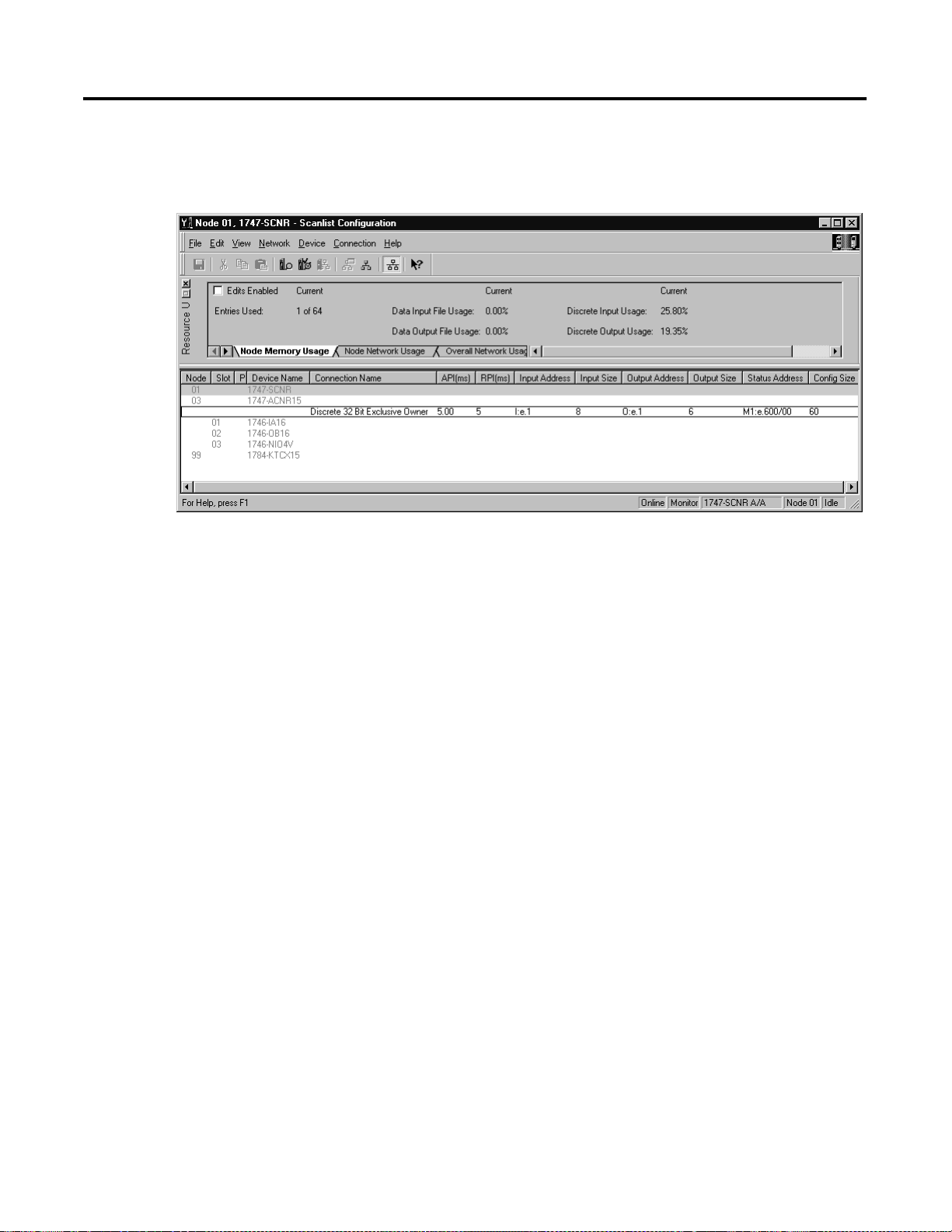
Click Apply, then OK. The Connection Properties window closes and the Scanlist
Configuration window appears and looks like the following:
You have now successfully configured your connection to read/write data
between the SLC processor and the remote ControlNet chassis. All that
remains is to Save this configuration to the network keeper which, in this case,
is the 1747-SCNR.
Click on the Save icon or choose the File pull-down menu and select Save. You
are prompted to Optimize and re-write schedule for all connections. Click OK,
then click YES to the subsequent warning message. Your network
configuration information is then written to the network keeper.
The display on the front of your 1747-SCNR should show a Full Glass next to
I/O. This indicates that all configured connections have been successfully
downloaded to the scanner. In addition, the A and OK LEDs should be solid
green and the B LED should be off, unless you are using the redundant media
option, which is not being used in this example. The 1747-ACN15 should be
displaying that it is active (ACTV) and its LEDs should be solid green for A
and OK.
Publication 1747-UM003 A-EN-P
Page 48

4-20 Application Examples
Create a Ladder Program
The final step is to write a ladder program for the SLC processor, including
configuring the 1747-SCNR for slot 3 of the processor’s chassis. After
downloading the program to your processor, place it into the RUN mode. Your
program should now be able to read data from the 1746-IA16 in word I:3.3
and write to the 1746-OB16 in word O:3.3. The analog input data resides in
words I:3.7 and I:3.8, while the analog output data must be copied to words
O:3.5 and O:3.6.
Note that your ladder program should also contain an unconditional rung with
an OTE instruction addressed to the SCNR scanner’s RUN/IDLE bit, O:3.0/
10 for this example. When the SLC processor is placed into the RUN mode,
this rung sets the SCNR scanner’s RUN/IDLE bit and places the scanner into
the RUN mode as well. The scanner begins executing the configured
connections when the RUN/IDLE bit is set.
Publication 1747-UM003A-EN-P
Page 49
Application Examples 4-21
Example 3
1747-SCNR ControlNet Scanner Controlling Discrete and Analog I/O on
ControlNet via a 1747-ACN15 ControlNet Adapter Using Rack and Module
Connections
This example is organized into the following sections:
• Hardware Setup
• Configuring The ControlNet Network with RSNetWorx™ for
ControlNet
• Create a Ladder Logic Program
Hardware Setup
The following hardware setup is referenced throughout this example.
Computer with:
• RSLogix 500 Software
• RSLinx Software
• RSNetWorx Software for ControlNet
• 1784-KTCX15 ControlNet PC Card
tap
tap
ControlNet
SLC 5/04
tap
1747-SCNR
1747-ACN15
1746-IA16
1746-OB16
1746-NI8
Publication 1747-UM003 A-EN-P
Page 50
4-22 Application Examples
Configuring The ControlNet Network with RSNetWorx™ for ControlNet
Start RSNetWorx for ControlNet by double clicking on its icon. The following
screen appears:
Publication 1747-UM003A-EN-P
At this point, you could configure your ControlNet network off-line and then
download it to the network. This example, instead, goes on-line and configure
the network. Therefore, click on the on-line icon or click on the Network
pull-down menu and select On-line.
A Browse for Network window appears, where you must select the
communication path previously configured in RSLinx for communicating
with your ControlNet network. In this example, a KTC ControlNet PC card
was used. Click on the KTC card to select it and then click OK.
Page 51

Application Examples 4-23
The software attempts to communicate with all possible node numbers on the
network, from 1 to 99. Click on the Edits Enabled box allow changes to be
made. For this example, the on-line network screen should look like the
following, where node 99 is the programming terminal.
Node 1 is the 1747-SCNR and node 3 is the 1747-ACN15. The
1747-ACN15 resides in slot 0 of its chassis, while slot 1 contains a 1746-IA16,
slot 2 contains a 1746-OB16, and slot 3 contains a 1746-NI8. For this
example, 2 separate ControlNet connections are configured. The first is a
Discrete 16 Bit Exclusive Owner rack connection for the 2 discrete I/O modules
and the second is an Module Connection to the 1746-NI8 8-input analog
module.
Before creating these necessary connections, verify the chassis configuration for
the 1747-ACN15 chassis. To do this, right click on the 1747-ACN15, then
choose Edit Chassis. Verify that the chassis configuration is as follows:
slot 0: 1747-ACNR15
slot 1: 1746-IA16
slot 2: 1746-OB16
slot 3: 1746-NI8
If the chassis is not already configured, manually configure it by dragging the
appropriate modules from the list on the right to the proper slot on the left of
the chassis configuration screen. When on-line, the software reads the module
types for you. When this is complete, click Apply, then OK.
Publication 1747-UM003 A-EN-P
Page 52
4-24 Application Examples
Configuring a Rack Connection
You are now ready to configure the necessary ControlNet connections to read/
write data from the SLC processor to the discrete I/O modules and to the
analog input module. Right click on the 1747-SCNR and choose Scanlist
Configuration. (If you are prompted to enter the edit mode, click YES.) The
following screen appears:
Publication 1747-UM003A-EN-P
Page 53

Application Examples 4-25
As you can see, the 1747-SCNR and 1747-ACN15 are shown as nodes 1 and 3
respectively. Under the 1747-ACN15, the 3 I/O modules in slots 1 through 3
of the 1747-ACN15 chassis are listed. In order to establish a 16-bit rack
connection to the 1747-ACN15 chassis, right click on the 1747-ACN15 and
choose ControlNet Configuration. The following window opens:
Note that addresses in the Connection Properties screen above are already filled
in. To have RSNetWorx choose the next available valid I/O or M-file addresses
for all connections, click on the Auto Address Preferences button. Next, click on
the box next to Enable Automatic Addressing on Insert so a check mark appears
in the box. Then click OK. Automatic Addressing enabled is the default.
IMPORTANT
RSNetWorx allows more than one exclusive owner rack
connection type to be configured to a 1747 adapter (e.g.
8-bit exclusive owner, 16-bit exclusive owner, and 32-bit
exclusive owner), however only one exclusive owner rack
connection can be operational at one time. It is
recommended that only one exclusive owner rack
connection type be configured to the adapter to avoid
contention between multiple connections.
Publication 1747-UM003 A-EN-P
Page 54

4-26 Application Examples
IMPORTANT
If a rack connection type is changed to a smaller bit
configuration e.g. 32-bit to 16-bit, or 16-bit to 8-bit, the
unused bits for the new connection remains in their
previously programmed states for program mode or lost
communications e.g. last state, safe state, reset off.
The Connection Name by default is Discrete 16-Bit Exclusive Owner and this is
the 16-bit rack connection you want. The first available I/O addresses are I:3.1
and O:3.1, where the 1747-SCNR is in slot 3 of the processor chassis. The first
available starting I/O addresses have been placed into the Input Address and
Output Address fields, because automatic addressing was previously selected in
the Auto Address Preference screen. Words I:3.0 and O:3.0 are used for status
and control data.
Note that the input data from the 1746-IA16 is found in the processor’s input
image word I:3.3 and the output data written to the 1746-OB16 module is
from the processor’s output image word O:3.2.
NOTE
There is a 2-word offset for input data for rack
connections. Therefore, for this example, the input data for
the input module in slot 1 of the remote 1747-ACN15
chassis is written to I:3.3 in the SLC processor’s input
image.
The starting input address configured in RSNetWorx for
this rack connection was I:3.1, but I:3.1 and I:3.2 are used
for rack slot st atus information. Therefore, the actual input
data begins after the 2 words of status information. I:3.4
and I:3.5 are not used in this example because an output
module resides in slot 2 and an analog module resides in
slot 3.
Also, note that there is no offset for the outputs in a rack
connection. O:3.2 is the output image word written to the
output module located in slot 2 of the 1747-ACN15
chassis. O:3.1 is not used because an input module resides
in slot 1. In addition, no offset applies to module
connections at all.
The Status Address field must also be filled in. This field supplies Connection
Status information to the processor for each unique connection. The starting
bit address for this field must be an even number because two consecutive bits
are used as status for each connection. The even numbered bit indicates
whether the connection is open or closed. The odd numbered bit indicates
whether the connection is in normal operation or Idle mode. In this example,
the starting address chosen is the first available bit pair, M1:3.600/00.
Publication 1747-UM003A-EN-P
Page 55

Application Examples 4-27
You have successfully configured a rack connection to the remote chassis to
communicate with the two discrete I/O modules. At this point you may also
configure the state of the outputs in the remote ControlNet chassis when the
processor is placed into the Program Mode or if communications are lost to the
remote chassis. This is optional. The default is to turn all outputs off when one
of the two conditions occur. To select other options, click on the Advanced tab
in the Connection Properties window. The following window appears:
By default, outputs in all slots in the remote chassis are reset if the processor is
placed into the Program mode or if communications are lost for any reason.
Two other choices are offered when one of the two conditions occur. They are:
• Hold Last Outputs
• Outputs to Safe State
Hold Last Output holds outputs in their last state if one of the two conditions
occur. Safe State allows you to choose the exact state of each output. If Safe
State is selected, you must click on the Configuration Settings tab and enter you
Safe State data for each output word in decimal. Then, if the SLC processor is
placed in the Program mode or if communications are lost to the ACN adapter,
the outputs revert to the Safe State data you entered for each output word.
Publication 1747-UM003 A-EN-P
Page 56

4-28 Application Examples
Configuring a Module Connection
Next, you need to configure a module connection for the 1746-NI8 8-input
analog module. If the previous window is still open, click Apply, then OK to
accept the rack connection.
Right click on the 1746-NI8 module in the Scanlist Configuration window and
select Insert Connection. A Connection Properties window again appears. Choose
Exclusive Owner for the Connection Name.
In this case choose M-file addresses for the 8-input analog module. The NI8
module must use Class 3 operation in a 1747-ACN15 chassis. It requires 12
output words and 16 input words. M-file words are used for this in the
1747-SCNR. M0:3.3 through M0:3.14 are used for the 12 output words to
configure the module. M1:3.3 through M1:3.18 are used for the input
information, including actual analog data and analog channel status. Refer to
your 1746-NI8 User’s Manual for additional information on this module.
M-file words M1:3.0 through M1:3.2 and M0:3.0 through M0:3.2 are
reserved. The next available Status Address is M1:3.600/02 since bits 0 and 1
are used by the 1747-SCNR for the rack connection. The Connection Properties
window for the module connection should look like the following.
Publication 1747-UM003A-EN-P
Page 57

4-29
Click Apply, then OK. The Connection Properties window closes and the Scanlist
Configuration window appears and looks like the following:
You have now successfully confi gured your two connections to read/write
data between the SLC processor and the remote ControlNet chassis. All that
remains is to Save this configuration to the network keeper which, in this case,
is the 1747-SCNR.
Click on the Save icon or choose the File pull-down menu and select Save. You
are prompted to Optimize and re-write schedule for all connections. Click OK, then
click YES to the subsequent warning message. Your net work configuration
information is then written to the network keeper.
The display on the front of your 1747-SCNR should show a Full Glass next to
I/O. This indicates that all configured connections were successfully
downloaded to the scanner. In addition, t he A and OK LEDs should be solid
green and the B LED shou ld be of f, unless you are using the redundant media
option, which is not being used in this example. The 1747-ACN15 should be
displaying that it is active (ACTV) and its LEDs should be solid green for A
and OK and the B LED should be off.
Publication 1747-UM003 A-EN-P
Page 58

4-30
Create a Ladder Logic Program
The final step is to write a ladder program for the SLC processor, including
configuring the 1747-SCNR for slot 3 of the processor’s chassis. After
downloading the program to your processor, place it into the RUN mode.
Your program should now be able to read data from the 1746-IA16 in word
I:3.3 and write to the 1746-OB16 in word O:3.2. The analog input data and
channel status will reside in words M1:3.3 through M1:3.18, while the analog
module configuration data must be copied to words M0:3.3 through M0:3.14.
Note that your ladder program should also contain an unconditional rung with
an OTE instruction addressed to the SCNR scanner’s RUN/IDLE bit,
O:3.0/10 for this example. When the SLC processor is placed into the RUN
mode, this rung sets the SCNR scanner’s RUN/IDLE bit and places the
scanner into the RUN mode as well. The scanner begins executing the
configured connections when the RUN/IDLE bit is set.
Publication 1747-UM003A-EN-P
Page 59

4-31
Example 4
1747-SCNR ControlNet Scanner Controlling Discrete I/O and Serial Data with
a 1746-BAS Module on ControlNet via a 1747-ACN15 ControlNet Adapter
Using Rack and Module Connections
This example is organized into the following sections:
• Hardware Setup
• Configuring The ControlNet Net work with RSNetWorx™ for ControlNet
• Create Ladder Logic and Basic Module Programs
Hardware Setup
The following hardware setup is referenced throughout this example.
Computer with:
• RSLogix 500 Software
• RSLinx Software
• RSNetWorx Software for ControlNet
• 1784-KTCX15 ControlNet PC Card
tap
tap
ControlNet
SLC 5/04
tap
1747-SCNR
1747-ACN15
1746-IA16
1746-OB16
1746-BAS, Series B
Publication 1747-UM003 A-EN-P
Page 60

4-32
Configuring The ControlNet Network with RSNetWorx™ for ControlNet
Start RSNetWorx for ControlNet by double clicking on its icon. The following
screen appears:
Publication 1747-UM003A-EN-P
At this point, you could configure your ControlNet network off-line and then
download it to the network. This example, instead, goes on-line and configure
the network. Therefore, click on the on-line icon or click on the Network
pull-down menu and select On-line.
A Browse for Network window appears, where you must select the
communication path previously configured in RSLinx for communicating
with your ControlNet network. In this example, a KTCX ControlNet PC card
was used. Click on the KTCX15 card to select it and then click OK.
Page 61

4-33
The software attempts to communicate with all possible node numbers on the
network, from 1 to 99. Click on the Edits Enabled box to allow changes to be
made. For this example, the on-line network screen should look like the
following, where node 99 is the programming terminal.
Node 1 is the 1747-SCNR and node 3 is the 1747-ACN15. The
1747-ACN15 resides in slot 0 of its chassis, while slot 1 contains a 1746-IA16,
slot 2 contains a 1746-OB16, and slot 3 contains a Series B 1746-BAS. For
this example, 2 separate ControlNet connections are configured. The first is a
Discrete 16 Bit Exclusive Owner rack connection for the 2 discrete I/O modules
and the second is an Exclusive Owner - Advanced module connection to the
1746-BAS module.
Before creating these necessary connections, verify the chassis configuration for
the 1747-ACN15 chassis. To do this, right click on the 1747-ACN15, then
choose Edit Chassis. Verify that the chassis configuration is as follows:
slot 0: 1747-ACNR15
slot 1: 1746-IA16
slot 2: 1746-OB16
slot 3: 1746-BAS
If the chassis is not already configured, manually configure it by dragging the
appropriate modules from the list on the right to the proper slot on the left of
the chassis configuration screen. When on-line, the software reads the module
types for you. When this is complete, click Apply, then OK.
Publication 1747-UM003 A-EN-P
Page 62

4-34
Configuring a Rack Connection
You are now ready to configure the necessary ControlNet connections to read/
write data from the SLC processor to the discrete I/O modules and to the Basic
module. Right click on the 1747-SCNR and choose Scanlist Configuration. (If
you are prompted to enter the edit mode, click YES.) The following screen
appears:
As you can see, the 1747-SCNR and 1747-ACN15 are shown as nodes 1 and 3
respectively. Under the 1747-ACN15, the 3 I/O modules in slots 1 through 3
of the 1747-ACN15 chassis are listed. In order to establish a 16-bit rack
connection to the 1747-ACN15 chassis, right click on the 1747-ACN15 and
choose Insert Connection. The following window opens:
Publication 1747-UM003A-EN-P
Page 63

4-35
NOTE
There is a 2-word offset for input data for rack connections.
Therefore, for this example, the input data for the input
module in slot 1 of the remote 1747-ACN15 chassis is
written to I:3.3 in the SLC processor’s input image.
The starting input address configured in RSNetWorx for
this rack connection was I:3.1, but I:3.1 and I:3.2 are used
for status information. Therefore, the actual input data
begins after the 2 words of status information. I:3.4 is not
used in this example because an output module resides in
slot 2.
Also, note that there is no offset for the outputs in a rack
connection. O:3.2 is the output image word written to the
output module located in slot 2 of the 1747-ACN15
chassis. O:3.1 is not used because an input module resides
in slot 1. In addition, no offset applies to module
connections at all.
Publication 1747-UM003 A-EN-P
Page 64

4-36
IMPORTANT
RSNetWorx allows more than one exclusive owner rack
connection type to be configured to a 1747 adapter (e.g.
8-bit exclusive owner, 16-bit exclusive owner, and 32-bit
exclusive owner), however only one exclusive owner rack
connection can be operational at one time. It is
recommended that only one exclusive owner rack
connection type be configured to the adapter to avoid
contention between multiple connections.
IMPORTANT
If a rack connection type is changed to a smaller bit
configuration e.g. 32-bit to 16-bit, or 16-bit to 8-bit, the
unused bits for the new connection remains in their
previously programmed st ates for program mode or lost
communications e.g. last state, safe state, reset off.
You have successfully configured a rack connection to the remote chassis to
communicate with the two discrete I/O modules. At this point you may also
configure the state of the outputs in the remote ControlNet chassis when the
processor is placed into the Program Mode or if communications are lost to the
remote chassis. This is optional. The default is to turn all outputs off when one
of the two conditions occur. To select other options, click on the Advanced tab
in the Connection Properties window. The following window appears:
Publication 1747-UM003A-EN-P
Page 65

4-37
By default, outputs in all slots in the remote chassis are reset if the processor is
placed into the Pr ogram mode or if communication s are lost for any reason.
Two other choices are offe red when one of the two conditions occur. They
are:
• Hold Last Outputs
• Outputs to Safe State
Hold Last Outputs holds outputs in their last state if one of the two conditions
occur. Safe State allows you to choose the exact state of each output. If Safe
State is selected, you must click on the Configuration Settings tab and enter you
Safe State data for each output word in decimal. Then, if the SLC processor is
placed in the Program mode or if communications are lost to the ACN adapter,
the outputs revert to the Safe State data you entered for each output word.
Publication 1747-UM003 A-EN-P
Page 66

4-38
Configuring a Module Connection
Next, you need to configure a module connection for the 1746-BAS module.
If the previous window is still open, click Apply, then OK to accept the rack
connection.
Right click on the 1746-BAS module in the Scanlist Configuration window and
select Insert Connection. A Connection Properties window again appears. Choose
Exclusive Owner-Advanced for the Connection Name.
In this case, you must choose M-file addresses for this type of connection. The
series B Basic module communicates via 8 I/O words and 64 M1 and 64 M0
file words. These Basic module M-file words are independent of the M-file
words used to transfer up to 72 words to and from the Basic module. Those 72
M0 and 72 M1 file words reside in the 1747-SCNR and are used to store the
data sent to the 1747-ACN15 from the SLC-5/04 processor and to store the
data received from the 1747-ACN15 for the SLC-5/04 processor.
The M0 file words in the 1747-SCNR, which are assigned in the Connection
Properties screen, are M0:3.3 through M0:3.74. These are the 72 words sent
from the SLC-5/04 processor to the 1747-SCNR. Words M1:3.3 through
M1:3.74 are the 72 words received from the 1747-ACN15. M-file words
M1:3.0 through M1:3.2 and M0:3.0 through M0:3.2 are reserved (refer to the
1747-SCNR User Manual for details). The next available Status Address is
M1:3.600/02, since bits 0 and 1 are used for the rack connection. The
Connection Properties window for the module connection should look like the
following.
Publication 1747-UM003A-EN-P
Page 67

4-39
You must now configure this connection for the 8 I/O words and the
64 M0/M1 file words. Click on the “Advanced” tab in the Connection Properties
window. The following screen appears:
Publication 1747-UM003 A-EN-P
Page 68

4-40
By default, the Chunk 1 Output File is the output image file for the Basic
module and the Chunk 1 Input File is the input image file for the Basic
module. You must then assign the Chunk 2 Output File as the Basic module’s
M0 file and the Chunk 2 Input File as the Basic module’s M1 file.
The size for each of these files is 64 words. The total number of words
transferred bi-directionally between the SLC processor and the Basic module
will be 72. The first 8 will be the Basic module’s I/O image and the last 64
words will be the Basic module’s M-file words. This order is determined by the
Chunk numbers. The Advanced screen should then look like the following:
Publication 1747-UM003A-EN-P
Page 69

4-41
Safe State data is available under the Configuration Settings tab. For 1746-BAS
module connections, it is recommended that outputs be reset to 0 when the
SLC processor is placed into the PROGRAM mode or if communications are
lost to the 1747-ACN15. The Hold Last State option is not available for the
1746-BAS.
Click Apply, then OK. The Connection Properties window closes and the Scanlist
Configuration window appears and looks like the following:
Publication 1747-UM003 A-EN-P
Page 70

4-42
You have now successfully configured your two connections to read/write data
between the SLC processor and the remote ControlNet chassis. All that
remains is to Save this configuration to the network keeper which, in this case,
is the 1747-SCNR.
Click on the Save icon or choose the File pull-down menu and select Save. You
are prompted to Optimize and re-write schedule for all connections. Click OK,
then click YES to the subsequent warning message. Your network
configuration information is then written to the network keeper.
The display on the front of your 1747-SCNR should show a Full Glass next to
I/O. This indicates that all configured connections were successfully
downloaded to the scanner. In addition, the A and OK LEDs should be solid
green and the B LED should be off, unless you are using the redundant media
option, which is not being used in this example. The 1747-ACN15 should be
displaying that it is active (ACTV) and its LEDs should be solid green for A
and OK.
Publication 1747-UM003A-EN-P
Page 71

4-43
Create Ladder Logic and Basic Module Programs
The final step is to write a ladder program for the SLC processor and a BASIC
program for the Basic module. After downloading the program to your
processor and to your basic module, place the processor into the RUN mode
and run your BASIC program as well. Your programs should now be able to
read data from the 1746-IA16 in word I:3.3 and write to the 1746-OB16 in
word O:3.2.
The attached BASIC program contains a CALL 23 interrupt CALL for PRT1
and a CALL 22 interrupt CALL for PRT2. The CALL 23 sends data out PRT1
when data is received from the SLC processor and CALL 22 transfers data sent
in PRT2 to the SLC. Remember, the first 8 words beginning with M1:3.3 and
M0:3.3 are from the Basic module’s Input and Output image. The following
64 words are from the Basic module’s M1 and M0 files. The handshaking
required between the SLC processor and the Basic module to transfer data, is
shown in the ladder logic program to follow.
Please refer to the 1746-BAS User Manual for a complete description of CALL
22 and 23, as well as the required handshaking. The only difference in the
handshake logic when using these Basic module CALLs is that the I/O image
words used for the handshaking are stored in the SCNR’s M-files, so they
appear as M-file addresses in the ladder logic instead of I/O addresses.
Connect an RS-232 cable between PRT1 and PRT2 on the Basic module. A
1747-CP3 cable works for this purpose. When up to 64 words of data are
placed into the SLC processor’s data table beginning at N12:0, it is sent to the
1747-SCNR, then to the Basic module via ControlNet and the 1747-ACN15
and is ultimately sent out PRT1 of the BAS module. If you used a cable to loop
the data back in PRT2, this data is sent to the 1747-SCNR via ControlNet and
ultimately appears in the SLC processor’s data table beginning with address
N13:0.
Note that your ladder program should also contain an unconditional rung with
an OTE instruction addressed to the 1747-SCNR scanner’s RUN/IDLE bit,
O:3.0/10 for this example. When the SLC processor is placed into the RUN
mode, this rung sets the 1747-SCNR scanner’s RUN/IDLE bit and places the
scanner into the RUN mode as well. The scanner begins executing the
configured connections when the RUN/IDLE bit is set.
Publication 1747-UM003 A-EN-P
Page 72

4-44
When the Basic module is placed into the RUN mode, any data placed into
the SLC processor’s data table beginning with N12:0 is sent to the
1747-SCNR, which sends it to the 1747-ACN15 via ControlNet and then to
the Basic module. The Basic module sends the data out PRT1 and this data is
looped right back in the Basic module’s PRT2. The module sends the data to
the 1747-ACN15, which sends it to the SCNR via ControlNet. The SLC
processor then retrieves this data and places it into its data table beginning at
N13:0.
Basic Module BASIC Program Listing
10 REM Test Program for CNET
20 MODE(PRT1,9600,N,8,1,N,R)
30 MODE(PRT2,9600,N,8,1,N,R)
40 PUSH 2
50 CALL 37
60 PUSH 2
70 CALL 96
80 REM CALL 23 for PRT1
90 PUSH 2
100 REM SEND DATA OUT PRT1
110 PUSH 1
120 REM GET DATA FROM M0 FILE
130 PUSH 0
140 REM NO OFFSET
150 PUSH 0
160 REM NO STRING USED
170 PUSH 1
180 REM ENABLE BYTE SWAPPING
190 CALL 23
200 POP S1
210 REM STATUS OF CALL 23 SETUP
220 IF (S1<>0) THEN P. "UNSUCCESSFUL CALL 23 SETUP"
230 REM CALL 22 FOR PRT2
240 PUSH 2
250 REM GET DATA FROM PRT2
260 PUSH 126
270 REM MAXIMUM OF 126 CHARACTERS PER TRANSFER
280 PUSH 13
290 REM CR TERMINATION CHARACTER
300 PUSH 1
310 REM SEND DATA TO M1 FILE
320 PUSH 0
330 REM NO OFFSET
340 PUSH O
350 REM NO STRING
360 PUSH 1
370 REM ENABLE BYTE SWAPPING
380 CALL 22
390 POP S2
400 REM CALL 22 SETUP STATUS
410 IF (S2<>0) THEN P. "UNSUCCESSFUL CALL 22 SETUP"
420 GOTO 420
Publication 1747-UM003A-EN-P
Page 73

SLC Processor Ladder Program
This rung gives the next rung a false-to-true transition every 1 second.
4-45
0000
0001
0002
0003
T4:1
TON
Timer On Delay
DN
Timer T4:1
Time Base 0.01
Preset 100<
Accum 86 <
This rung copies up to 64 words (beginning with N12:0) to
the SCNR for transfer to the Basic module on ControlNet.
T4:1
Copy File
DN
Source #N12:0
Dest #M0:3.11
Length 64
This rung completes the handshaking between the SLC processor
and, ultimately, the Basic module to accomplish the CALL 23.
CALL 23 Input Handshake Bit
M1:3.3
6
This rung copies up to 64 words of data received from the Basic module when the
handshake bit, M1:3.3/9, is set. When data is received by the Basic module in PRT2,
the CALL 22 transfers it to the SCNR and, ultimately, to the SLC processor.
CALL 22 Input Handshake Bit
M1:3.3
Copy File
9
Source #M1:3.11
Dest #N13:0
Length 64
EN
DN
COP
CALL 23 Output
Handshake Bit
M0:3.3
L
6
CALL 23 Output Handshake Bit
M0:3.3
U
6
COP
0004
0005
CALL 22 Output
Handshake Bit
M0:3.3
9
1747-SCNR
RUN/IDLE Bit
O:3
10
1747-SCNR
END
Publication 1747-UM003 A-EN-P
Page 74

4-46
Example 5
1747-SCNR ControlNet Scanner Controlling Discrete I/O and Specialty
Modules Requiring M0 File Configuration on ControlNet via a 1747-ACN15
ControlNet Adapter Using Rack and Module Connections
This example is organized into the following sections:
• Hardware Setup
• Configuring The ControlNet Network with RSNetworx for ControlNet
• Create Ladder Logic
Hardware Setup
The following hardware setup is referenced throughout this example.
Computer with:
• RSLogix 500 Software
• RSLinx Software
• RSNetWorx Software for ControlNet
• 1784-KTCX15 ControlNet PC Card
tap
tap
ControlNet
SLC 5/04
tap
1747-SCNR
1747-ACN15
1746-IA16
1746-OB16
1746-HSCE
Publication 1747-UM003A-EN-P
Page 75

4-47
Configuring The ControlNet Network with RSNetWorx for ControlNet
Start RSNetWorx for ControlNet by double clicking on its icon. The following
screen should appear:
At this point, you could configure your ControlNet network off-line and then
download it to the network. This example will, instead, go on-line and
configure the network. Therefore, click on the on-line icon or click on the
Network pull-down menu and select On-line.
A Browse for Network window appears, where you must select the
communication path previously configured in RSLinx for communicating with
your ControlNet network. In this example, a KTC ControlNet PC card was
used. Click on the KTC card to select it and then click OK.
Publication 1747-UM003 A-EN-P
Page 76
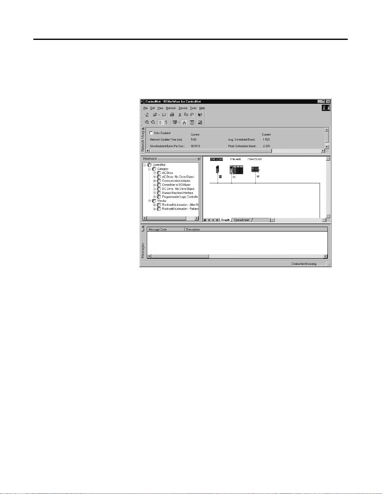
4-48
The software attempts to communicate with all possible node numbers on the
network, from 1 to 99. Click on the Edits Enabled box allow changes to be
made. For this example, the on-line network screen should look like the
following, where node 99 is the programming terminal.
Node 1 is the 1747-SCNR and node 3 is the 1747-ACN15. The 1747-ACN15
resides in slot 0 of its chassis, while slot 1 contains a 1746-IA16, slot 2 contains
a 1746-OB16, and slot 3 contains a 1746-HSCE. For this example, 2 separate
ControlNet connections are configured. The first is a Discrete 16 Bit Exclusive
Owner rack connection for the 2 discrete I/O module s and the second is an
Exclusive Owner Advanced (module connection) to the 1746-HSCE high
speed counter module.
Before creating these necessary connections, verify the chassis configuration
for the 1747-ACN15 chassis. To do this, right click on the 1747-ACN15, then
choose Edit Chassis. Verify that the chassis configuration is as follows:
slot 0: 1747-ACNR15
slot 1: 1746-IA16
slot 2: 1746-OB16
slot 3: 1746-HSCE
If the chassis is not already configured, manually configure it by dragging the
appropriate modules from the list on the right t o the proper slot on the left of
the chassis configur ation screen. When on-line, the software reads the modul e
types for you. When this is complete, click Apply, then OK.
Publication 1747-UM003A-EN-P
Page 77

4-49
Configuring a Rack Connection
You are now ready to configure the necessary ControlNet connections to
read/write data from the SLC processor to the discrete I/O modules and to
the high speed counter module. Right click on the 1747-SCNR and choose
Scanlist Configuration. (If you are prompted to enter the edit mode, click YES.)
The following screen appears:
Publication 1747-UM003 A-EN-P
Page 78

4-50
As you can see, the 1747-SCNR and 1747-ACN15 are shown as nodes 1 and 3
respectively. Under the 1747-ACN15, the 3 I/O modules in slots 1 through 3
of the 1747-ACN15 chassis are listed. In order to establish a 16-bit rack
connection to the 1747-ACN15 chassis, right click on the 1747-ACN15 and
choose ControlNet Configuration. The following window opens:
Publication 1747-UM003A-EN-P
Note that addresses in the Connection Properties screen above are already filled in.
To have RSNETWORX choose the next available valid I/O or M-file
addresses for all connections, click on the Auto Address Preferences button. Next,
click on the box next to Enable Automatic Addressing on Insert so a check mark
appears in the box. Then click OK. Automatic Addressing enabled is the
default.
IMPORTANT
RSNetWorx allows more than one exclusive owner rack
connection type to be configured to a 1747 adapter (e.g.
8-bit exclusive owner, 16-bit exclusive owner, and 32-bit
exclusive owner), however only one exclusive owner rack
connection can be operational at one time. It is
recommended that only one exclusive owner rack
connection type be configured to the adapter to avoid
contention between multiple connections.
Page 79

4-51
IMPORTANT
If a rack connection type is changed to a smaller bit
configuration e.g. 32-bit to 16-bit, or 16-bit to 8-bit, the
unused bits for the new connection remains in their
previously programmed st ates for program mode or lost
communications e.g. last state, safe state, reset off.
The Connection Name by default is Discrete 16-Bit Exclusive Owner and this is the
16-bit rack connection you want. The first available I/O addresses are I:3.1
and O:3.1, where the 1747-SCNR is in slot 3 of the processor chassis. The first
available starting I/O addresses have been placed into the Input Address and
Output Address fields, because automatic addressing was previously selected in
the Auto Address Preference screen. Wo rd s I:3.0 and O:3.0 are used for status and
control data.
Note that the input data from the 1746-IA1 6 is found in the proces sor’s input
image word I:3.3 and the output data written to the 1746-OB16 module is
from the processor’s output image word O:3.2.
NOTE
There is a 2-word offset for input data for rack
connections. Therefore, for this example, the input data for
the input module in slot 1 of the remote 1747-ACN15
chassis is written to I:3.3 in the SLC processor’s input
image.
The starting input address configured in RSNetWorx for
this rack connection was I:3.1, but I:3.1 and I:3.2 are used
for rack slot st atus information. There fore, the actual input
data begins after the 2 words of status information. I:3.4
and I:3.5 are not used in this example because an output
module resides in slot 2 and an analog module resides in
slot 3.
Also, note that there is no offset for the outputs in a rack
connection. O:3.2 is the output image word written to the
output module located in slot 2 of the 1747-ACN15
chassis. O:3.1 is not used because an input module resides
in slot 1. In addition, no offset applies to module
connections at all.
The Status Addr ess field must also be filled in. This field supplies Connection
Status information to the processor for each unique connection. The starting
bit address for this field must be an even number because two consecutive bits
are used as status for each connection. The even numbered bit indicates
whether the connectio n is open or closed. The odd numbere d bit indicates
whether the connection is in normal operation or Idle mode. In this example,
the starting address chosen is the first available bit pair, M1:3.600/00.
Publication 1747-UM003 A-EN-P
Page 80

4-52
You have successfully configured a rack connection to the remote chassis to
communicate with the two discrete I/O modules. At this point you may also
configure the state of the o utputs in the remote Control Net chassis when the
processor is placed into the Program Mode or if communications are lost to the
remote chassis. This is optional. The default is to turn all outputs off when one
of the two conditions occur. To select other options, click on the Advanced tab
in the Connection Properties window. The following window appears:
Publication 1747-UM003A-EN-P
By default, outputs in all slots in the remote chassis are reset if the processor is
placed into the Pr ogram mode or if communications are lost for any reason.
Two other choices are offe red when one of the two conditions occur. They
are:
• Hold Last Outputs
• Outputs to Safe State
Hold Las t Outp uts holds outputs in their last state if one of the two condit ions
occur. Safe State allow s you to choose the exact state of each output. If Safe
State is selected, you must click on the Configuration Settings tab and enter you
Safe State data for each output word in decimal. Then, if the SLC processor is
placed in the Pr ogram mode or if communications are lost to the ACN adapter,
the outputs revert to the Safe State data you entered for each output word.
Page 81
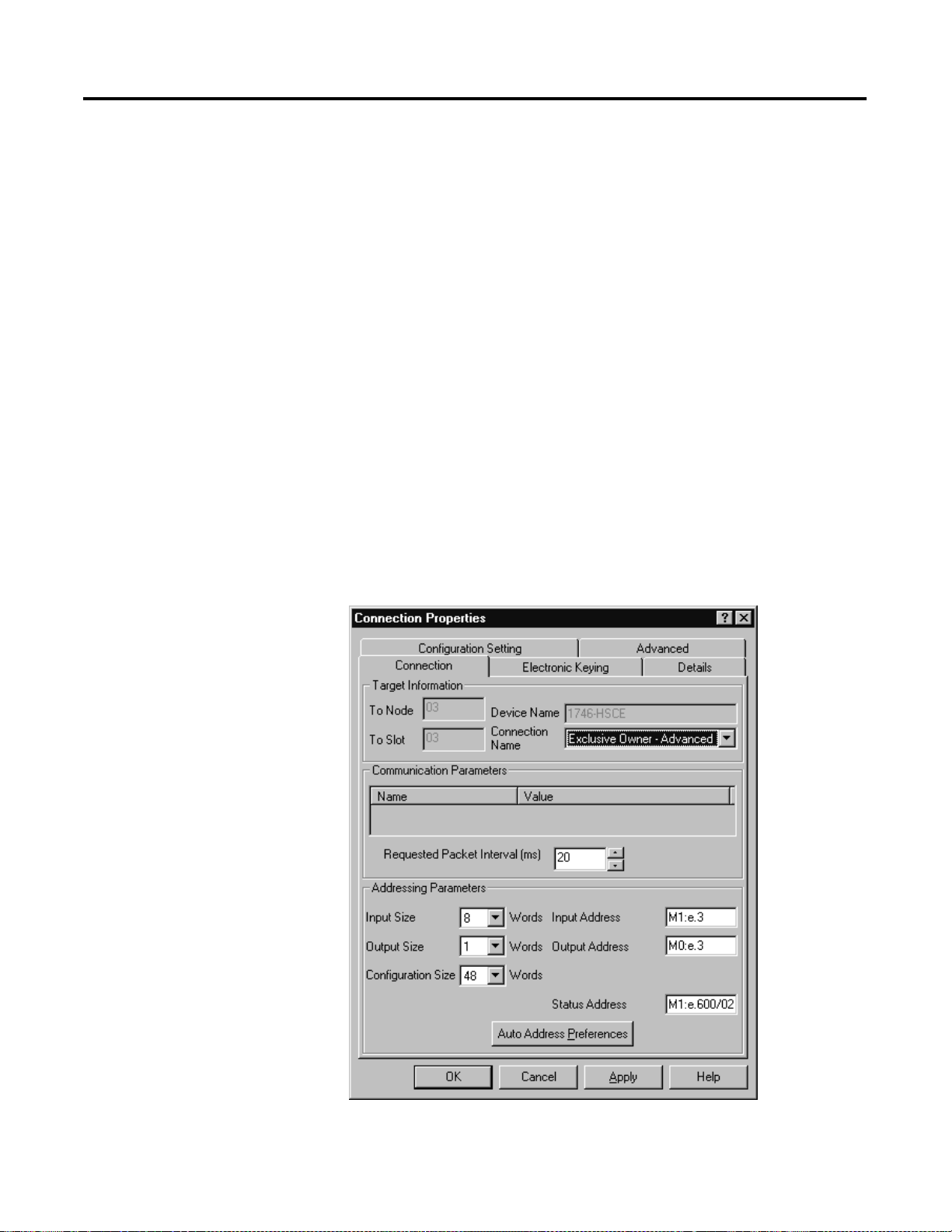
4-53
Configuring a Module Connection
Next, you need to configure a module connection for the 1746-HSCE high
speed counter module. If the previous window is still open, click Apply, then
OK to accept the rack connection.
Right click on the 1746-HSCE module in the Scanlist Configuration window and
select Insert Connection. A Connection Properties window again appears. Choose
Exclusive Owner Advanced for the Connection Name.
In this case choose M-file addresses for the high speed counter module. It
requires 1 output word and 8 input words. M-file words are used for this in the
1747-SCNR. M0:3.3 is used for the output word. M1:3.3 through M1:3.10 are
used for the input information. Refer to your 1746-HSCE User’s Manual for
additional information on this module.
M-file words M1:3.0 through M1:3.2 and M0:3.0 through M0:3.2 are reserved
(refer to the 1747-SCNR User Manual for details). The next available Status
Address is M1:3.600/02 since bits 0 and 1 are used for the rack connection. The
Connection Properties window for the module connection should look like the
following.
Publication 1747-UM003 A-EN-P
Page 82

4-54
Since the 1746-HSCE module uses 42 M0 file words for configuration, the
user must enter the configuration values under the Configurati on Setting tab so
that the 1747-SCNR scanner can write the configuration values each time a
module configuration i s made to the HSCE module. Below are the example
configuration values for set ting up the 1746-HSCE module in basic count- only
mode. See your 1746-HSCE User Manual for more information on
configuring the module.
Publication 1747-UM003A-EN-P
Page 83

4-55
Publication 1747-UM003 A-EN-P
Page 84

4-56
Click Apply, then OK. The Connection Properties window closes and the Scanlist
Configuration window appears and looks like the following:
You have now successfully confi gured your two connections to read/write
data between the SLC processor and the remote ControlNet chassis. All that
remains is to Save this configuration to the network keeper which, in this case,
is the 1747-SCNR.
Click on the Save icon or choose the File pull-down menu and select Save. You
are prompted to Optimize and re-write schedule for all connections. Click OK, then
click YES to the subs equent warning message. Your network configuration
information is then written to the network keeper.
The display on the front of your 1747-SCNR should show a Full Glass next to
I/O. This indicates that all configured connections were successfully
downloaded to the scanner. In addition, the A an d OK LEDs should be solid
green and the B LED should be of f, unless you are using the redundant media
option, which is not being used in this example. The 1747-ACN15 should be
displaying that it is active (ACTV) and its LEDs should be solid green for A
and OK.
Publication 1747-UM003A-EN-P
Page 85

4-57
Create a Ladder Logic Program
The final step is to write a ladder program for the SLC processor, including
configuring the 1747-SCNR for slot 3 of the processor’s chassis. After
downloading the program to your processor, place it into the RUN mode.
Your program should now be able to read data from the 1746-IA16 in word
I:3.3 and write to the 1746-OB16 in word O:3.2. The HSCE input data will
reside in words M1:3.3 through M1:3.18, while the HSCE module output data
must be copied to word M0:3.3.
Note that your ladder program should also contain an unconditional rung with
an OTE instruction addressed to the SCNR scanner’s RUN/IDLE bit,
O:3.0/10 for this example. When the SLC processor is placed into the RUN
mode, this rung sets the SCNR scanner’s RUN/IDLE bit and places the
scanner into the RUN mode as well. The scanner begins executing the
configured connections when the RUN/IDLE bit is set.
Publication 1747-UM003 A-EN-P
Page 86

4-58
Publication 1747-UM003A-EN-P
Page 87

Troubleshooting
Chapter
5
Chapter Objectives
Troubleshooting With the Status Indicators and Status Display
In this chapter, you will learn how to use the indicators on the module
frontplate for troubleshooting the module. This includes:
• troubleshooting with the status indicators and status display, including:
– health indicators and display mnemonics
– ControlNet status indicators
The module has indicators on the front plate, as shown below. These indicators
consist of:
• health indicators
• status indicators
• display of status and address
Use these indicators for troubleshooting the module.
ADDRESS/STATUS
OK OK
ADDRESS/STATUS
BAA
Status Display
and Net Address
Health Indicators and
ControlNet Status Indicators
B
A
1747-ACN
The following tables describe problems that may occur, probable causes, and
recommended courses of action.
1 Publication 1747-UM003 A-EN-P
A
1747-ACNR
Page 88

5-2 Troubleshooting
Health Indicators and Display Mnemonics
OK LED Display Description Probable Cause Recommended Action
Off None Module is not communicating. Power supply fault. Check power supply, and seat
adapter firmly in chassis.
None Module is not communicating. Defective adapter. Contact Allen-Bradley service.
POST Adapter is running Power On Self
Te s t.
None None
Amber 0000
through
9999
A/A Adapter is displaying Series and
INIT Adapter is loading and
Solid Red FATL
Number
Number
Flashing
Red
Flashing
Green
A#00 ERR Module is not communicating. The node address switches are
DUP NODE Module is not communicating. The adapter has detected a
IDLE
NET ERR Module is not communicating. The adapter has detected a cable
Adapter is running Power On Self
Te s t.
Revision level.
initializing operating system.
Module is not communicating. The Adapter has either failed a
None None
None None
None Adapter requires ControlNet
hardware test, or gone into a
state from which it cannot
recover. The numbers following
the FATL describe the problem in
detail.
set to 00 which is not valid.
duplicated node address on the
network.
fault and is attempting to
recover. The adapter is sending
the three “NET ERR” packets.
configuration.
Document the numbers. Power
cycle the adapter. Contact
Allen-Bradley service.
Power the adapter off, remove
the adapter from the chassis,
change the node address switch
to something other than 00,
replace the adapter in the
chassis, and apply power.
Correct the duplicate node
address problem.
None, check cable if problem
persists.
Solid Green ACTV A#XX Module is working properly. None None
BOOT
A#XX
CODE
UPDT
Publication 1747-UM003A-EN-P
Module is on network, but not
supporting any connections.
Firmware update mode. Adapter firmware is being
The main code in the module has
failed, or the main code is being
updated.
updated via ControlFlash update
utility.
Update the main code with the
latest Series and Revision code.
None
Page 89
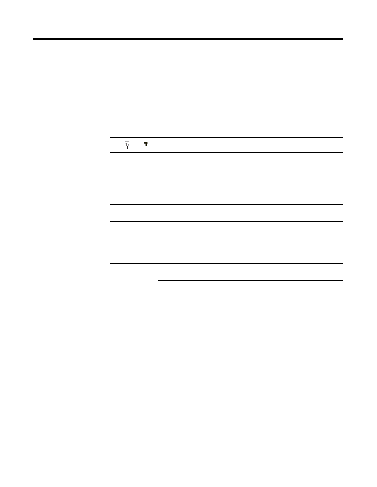
Troubleshooting 5-3
ControlNet Status Indicators
The following table explains module status when indicators are:
• steady - indicator is on continuously in the defined state.
• alternating - the two indicators alternate between the two defined states at
the same time (applies to both indicators viewed together). The two
indicators are always in opposite states, out of phase.
• flashing - the indicator alternates between the two defined states (applies to
each indicator viewed independent of the other). If both indicators are
flashing, they must flash together, in phase.
BA
Cause Action
Off No power None or power up
Steady red Faulted unit Cycle power
If fault persists, contact Allen-Bradley
representative or distributor.
Alternating red/
green
Alternating red/
off
Off Channel disabled Program network for redundant media, if required
Self-test None
Incorrect node
configuration
Check network address and other ControlNet
configuration parameters
Steady green Normal operation None
Flashing green/
off
Flashing red/off Media fault Check media for broken cables, loose connectors,
Flashing red/
green
Temporary errors None; unit will self-correct
Listen only Cycle power
missing terminators, etc.
No other nodes present
on network
Incorrect network
configuration
Add other nodes to the network
Cycle power or reset unit
If fault persists, contact Allen-Bradley
representative or distributor.
Publication 1747-UM003 A-EN-P
Page 90

5-4 Troubleshooting
Publication 1747-UM003A-EN-P
Page 91

Specifications
Description Specification
Module Location 1746 I/O chassis, leftmost slot
Appendix
A
Interconnect Cable Quad shield RG-6 coaxial cable - Refer to the
System Manual,
Power Dissipation 5 Watts
Thermal Dissipation 17.06 BTU/hr
Backplane Current 0.9A at 5V dc
Environmental Conditions:
• Operational Temperature
• Storage Temperature
• Relative Humidity
Agency Certification
(when product or packaging is
marked)
• +0°C to +60°C (+32F° to +140°F)
• -40C° to +85°C (-40F° to +185°F)
• 5% to 95% (without condensation)
• CSA certified
• CSA Class I, Division 2
Groups A, B, C, D certified
• UL listed
• CE compliant for all applicable directives
publication 1786-6.2 for more information.
ControlNet Cable
1 Publication 1747-UM003 A-EN-P
Page 92

A-2 Specifications
Publication 1747-UM003A-EN-P
Page 93

Appendix
B
Understanding Your SLC 500/1746 Control System
This appendix provides information on using SLC 500/1746 control systems. Topics
include:
• selecting your SLC 500/1746 control power supply
• system installation recommendations
• mounting your control system
• installing your I/O modules
• wiring the I/O modules
• calculating heat dissipation for your control system
When configuring a modular system, you must have an individual power supply for
each chassis. Careful system configuration results in the best performance. Excessive
loading of the power supply outputs can cause a power supply shutdown or
premature failure.
Selecting Your SLC 500/1746 Control Power Supply
There are three different ac power supplies and four dc power supplies. For ac power
supplies, the 120/240V selection is made by a jumper. Place the jumper to match the
input voltage. The power supply has an LED that illuminates when the power supply
is functioning properly. On the following page are the general specifications for the
power supplies.
1747-UM003A-US-P
Page 94

B-2 Understanding Your SLC 500/1746 Control System
Power Supply Specifications
Description: Specification: 1746-
P1 P2 P3 P4 P5 P6 P7
Line Voltage 85 to 132/170 to 265V ac 47
to 63 Hz
Typical Line
135 VA 180 VA 90 VA 240 VA 85 VA 100 VA 12V dc input:
Power Reqmnt.
Maximum
20A 45A 20A 20A (required for turn-on)
Inrush Current
Internal
Current
Capacity
Fuse
Protection
24V dc User
(2)
2A at 5V dc
0.46A at 24V
dc
1746-F1 or
equivalent
5A at 5V dc
0.96A at 24V
dc
1746-F2 or
(3)
equivalent
200 mA Not
Power Current
Capacity
24V dc User
18 to 30V dc 20.4 to 27.6V dc18 to 30V dc
Power Volt.
Range
Ambient
Operating
°C to +60°C (+32°F to +140°F)
0
Current capacity is derated 5% above +55
Temperature
Isolation
(6)
1800V ac RMS for 1s
19.2 to 28.8V dc85 to 130/170
3.6A at 5V dc
0.87A at 24V
dc
1746-F3 or
(4)
equivalent
Applicable
None
to 265V ac 47
90 to 146V dc 30 to 60V dc10 to 30V dc
to 63 Hz
24V dc input:
10.0A at 5V dc
2.88A at 24V
(1)
dc
5A at 5V dc
0.96A at 24V dc
50 VA
12V dc input:
2.0A at 5V dc
0.46A at 24V
dc
75 VA
24V dc input:
3.6A at 5V dc
0.87A at 24V
dc
Fuse is soldered in place.
(5)
°C.
(1)
1A
°C to +60°C
0
(+32
°F to
+140
°F) no
200mA Not Applicable
°C to +60°C (+32°F to +140°F)
0
Current capacity is derated 5% above +55
°C.
derating
(7)
2600V dc for 1s1800V ac RMS for 1s 600V ac RMS for 1s
CPU Hold-up
(8)
Time
20 ms (full load) 3000 ms (no
load)
5 ms (full
load)
1000 ms (no
load)
20 ms (full
load)
3000 ms (no
load)
20 ms (full
load)
3000 ms (no
load)
5 ms (full
load)
1500 ms
(no load)
12V dc input:
1.37 ms at 0V
dc (full load)
895 ms at 0V
dc (no load)
10 ms at 9V
dc (full load)
continuous at
9V dc (no
load)
24V dc input:
40 ms at 0V dc
(full load)
1860 ms at 0V
dc (no load)
790 ms at 11V
dc (full load)
continuous at
11V dc (no
load)
Certification UL listed
C-UL or CSA certified (as indicated by product or packaging markings)
CE compliant for all applicable directives
Hazardous
Class I, Division 2
Environment
Certification
(1) The combination of all output power (5 volt backplane, 24 volt backplane, and 24 volt user source) cannot exceed 70 watts.
(2) Power supply fuse is intended to guard against fire hazard due to short-circuit conditions. This fuse may not protect the supply from miswiring or excessive transient in the
power line.
(3) Equivalent fuses: 250V-3A fuse, Nagasawa ULCS-61ML-3, or BUSSMAN AGC 3.
(4) Equivalent fuse: 250V-3A fuse, SANO SOC SD4, or BUSSMAN AGC 3.
(5) Equivalent fuse: 125V-3A fuse, Nagasawa ULCS-61ML-5, or BUSSMAN AGC 5.
(6) Isolation is between input terminals and backplane.
(7) No isolation between input terminals and backplane. However, dielectric withstand between input terminals and chassis ground terminal is 600V ac RMS for 1s.
(8) CPU hold-up time is for 0V unless specified. Hold-up time is dependent on power supply loading.
Publication 1747-UM003A-EN-P
Page 95

Understanding Your SLC 500/1746 Control System B-3
Example for Selecting a 1746 Power Supply
Select a power supply for chassis 1 and chassis 2 for the control system below.
(The worksheets for this example start on Page B-4.)
Table B.1 Chassis 1
Chassis 1
PC
Chassis 2
? ?
1747-AIC
DH-485 Network
Chassis 1 Contains:
Slot
Number
0 Processor Unit 1747-L524 0.35 0.105
1 ControlNet Scanner 1747-SCNR 0.90 Not Applicable
2 Transistor Output
3 Triac Output Module 1746-OA16 0.37 Not Applicable
Peripheral
device
Description Catalog Number Power
Module
Isolated Link Coupler 1747-AIC Not
Total Current: 1.755
Slot Slot 012 3 012345 6
Power Supply at
Supply at 5V
24V dc (Amps)
dc (Amps)
1746-OB8 0.135 Not Applicable
0.085
Applicable
0.190
(1)
Table B.2 Chassis 2
(1) Power Supply 1746-P1 is sufficient for Chassis #1. The “Internal Current Capacity” for this power supply is 2 Amps at 5V
dc, 0.46 Amps at 24V dc.
Chassis 2 Contains:
Slot
Number
Description Catalog Number Power
Supply at 5V
dc (Amps)
0 ControlNet Adapter 1747-ACNR15 0.900 Not Applicable
1 Input Module 1746-IA16 0.085 Not Applicable
2 Input Module 1746-IA16 0.085 Not Applicable
3 Relay Output Modules 1746-OB32 0.452 Not Applicable
4 Relay Output Modules 1746-OB32 0.452 Not Applicable
5 Relay Output Modules 1746-OB32 0.452 Not Applicable
6 Combination Module 1746-IO12 0.09 0.07
Total Current: 2.616
(1) Power Supply 1746-P2 is sufficient for Chassis #2. The “Internal Current Capacity” for this power supply is 5 Amps at 5V dc,
0.96 Amps at 24V dc.
Publication 1747-UM003 A-EN-P
Power Supply at
24V dc (Amps)
(1)
0.07
Page 96

B-4 Understanding Your SLC 500/1746 Control System
Example - Worksheet for Selecting a 1746 Power Supply
Procedure
1. For each slot of the chassis that contains a module, list the slot number, the catalog number of the module, and its 5V and 24V
maximum currents.
Chassis Number: _______ Chassis Number: _______
slot _______
0
slot _______
1
slot _______
2
slot _______
3
slot _______
slot _______
slot _______
slot _______
Catalog
Number
_________
L524
_________
SCNR
_________
OB8
_________
OA16
_________
_________
_________
_________
Maximum Currents
5V 24V
______________
______________
______________
______________
0.350
0.900
0.135
0.370
0.105
NA
NA
NA
______________
______________
______________
______________
slot _______
0
slot _______
1
slot _______
2
slot _______
3
slot _______
4
slot _______
5
slot _______
6
slot _______
Catalog
Number
_ACNR15_
_________
IA16
_________
IA16
_________
OB32
_________
OB32
_________
OB32
_________
IO12
_________
Maximum Currents
5V 24V
______________
0.900
______________
0.085
______________
0.085
______________
0.452
______________
0.452
______________
0.452
______________
0.090
______________
NA
NA
NA
NA
NA
NA
0.070
Peripheral
Device
_________
AIC
______________
NA
0.190
Peripheral
Device
_________
______________
2. Add the power supply loading currents of
all the system devices ( at 5V and 24V).
Total Current:
When using the 1746-P4 power supply, use the formula below to calculate
total power consumption of all the system devices (at 5V and 24V). Note that
the 1746-P4 total power supply loading currents cannot exceed 70 W
you are not using a 1746-P4 power supply, proceed to step 3.
The user current @ 24V listed below is for example only. The current
required depends on the application.
Total current
@ 5V
x5V) + x24V)
Total current
@ 24V
+x
___________
User Current
@ 24V
24V)
0.1901.755
atts. If
Total Power
= W
Total current
@ 5V
+(
Total current
@ 24V
Total Current:
24V)
+
x5V)x
___________
User Current
@ 24V
x24V) = W
0.0702.516
Total Power
3. Compare the Total Current required for the chassis with the Internal Current Capacity of the power supplies.
To select the proper power supply for your chassis, make sure that the power supply loading current for the chassis is
less than
the
internal current capacity for the power supply, for both 5V and 24V loads.
Internal Current Capacity
5V 24V
Catalog Number 1746-P1
Catalog Number 1746-P2
Catalog Number 1746-P3
Catalog Number 1746-P4
Catalog Number 1746-P5
Catalog Number 1746-P6
Catalog Number 1746-P7
2.0A
5.0A
3.6A
10.0A
5.0A
5.0A
2.0A
(12V dc input)
3.6A
(24V dc input)
|
0.46A
| 0.96A
| 0.87A
| 2.88A
(70W maximum)
0.96A
|
0.96A
|
0.46A (12V dc input)
|
|
0.87A (24V dc input)
|
Required Power Supply for this Chassis: 1746-
Publication 1747-UM003A-EN-P
P1
Required Power Supply for this Chassis: 1746-
P2
Page 97
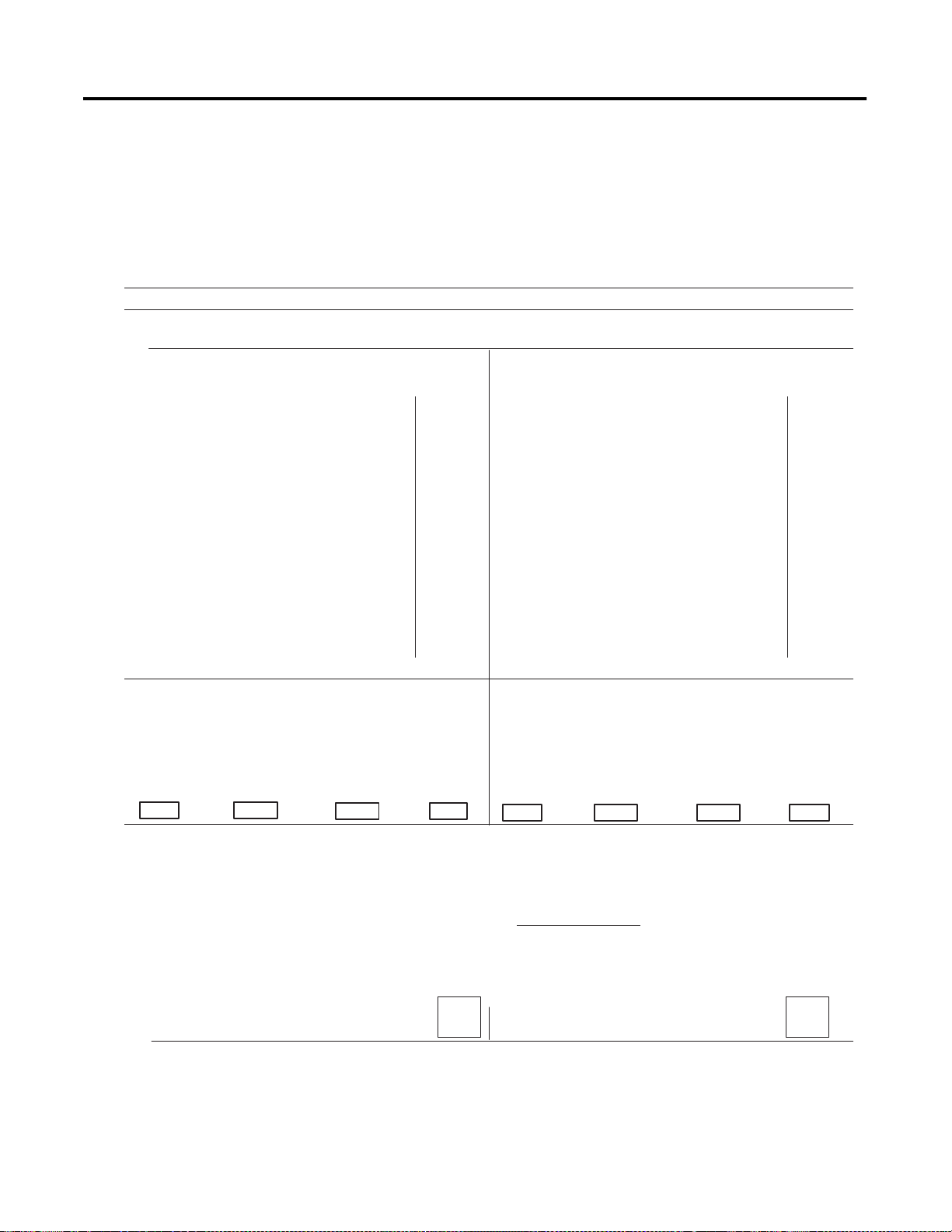
Understanding Your SLC 500/1746 Control System B-5
Worksheet for Selecting a 1746 Power Supply
Make copies of this worksheet as needed. For a detailed list of device load
currents, refer to the SLC 500 price sheet, product instruction sheet, or
appropriate product data.
Consider future system expansion when selecting a power supply.
Procedure
1. For each slot of the chassis that contains a module, list the slot number, the catalog number of the module, and its 5V and 24V
maximum currents.
Chassis Number: _______ Chassis Number: _______
slot _______
slot _______
slot _______
slot _______
slot _______
slot _______
slot _______
slot _______
Catalog
Number
_________
_________
_________
_________
_________
_________
_________
_________
Maximum Currents
5V 24V
______________
______________
______________
______________
______________
______________
______________
______________
slot _______
slot _______
slot _______
slot _______
slot _______
slot _______
slot _______
slot _______
Catalog
Number
_________
_________
_________
_________
_________
_________
_________
_________
Maximum Currents
5V 24V
______________
______________
______________
______________
______________
______________
______________
______________
Peripheral
Device
_________
______________
Peripheral
Device
_________
______________
2. Add the power supply loading currents of
all the system devices ( at 5V and 24V).
Total Current:
When using the 1746-P4 power supply, use the formula below to calculate
total power consumption of all the system devices (at 5V and 24V). Note that
the 1746-P4 total power supply loading currents cannot exceed 70 W
you are not using a 1746-P4 power supply, proceed to step 3.
The user current at 24V listed below is for example only. The current
required depends on the application.
Total current
at 5V
x5V) + x24V)
Total current
at 24V
+x
___________
User Current
at 24V
atts. If
Total Power
24V)
= W
Total current
at 5V
+(
Total current
at 24V
Total Current:
24V)
+
x5V)x
___________
User Current
at 24V
x24V) = W
Total Power
3. Compare the Total Current required for the chassis with the Internal Current Capacity of the power supplies.
To select the proper power supply for your chassis, make sure that the power supply loading current for the chassis is
less than
the
internal current capacity for the power supply, for both 5V and 24V loads.
Internal Current Capacity
5V 24V
Catalog Number 1746-P1
Catalog Number 1746-P2
Catalog Number 1746-P3
Catalog Number 1746-P4
2.0A
5.0A
3.6A
|
| 0.96A
| 0.87A
10.0A | 2.88A
0.46A
(70W maximum)
Required Power Supply for this Chassis: 1746-
Required Power Supply for this Chassis: 1746-
Publication 1747-UM003 A-EN-P
Page 98

B-6 Understanding Your SLC 500/1746 Control System
This section provides specific recommendations to help you install your SLC
500/1746 components. For general installation guidelines, also refer to the
requirements specific to your region.
SLC 500 System Installation Recommendations
• Europe: Reference the standards found in EN 60204 and your national
• United States: Refer to article 70E of the National Fire Protection
Typical Installation
The figure below consists of some components that make up a typical
installation.
(1) An IEC- or NEMA-rated enclosure suitable for your
application and environment that shields your adapter from
electrical noise and airborne contaminants.
(2) Disconnect device that allows you to remove power from
system.
(3) Fused isolation transformer or a constant voltage
transformer, as your application requires.
(4) Master control relay/emergency-stop circuit.
(5) Terminal blocks or wiring ducts.
(6) Suppression devices for limiting electromagnetic
interference (EMI) generation.
regulations.
Association (NFPA). It describes electrical safety requirements for
employee workplaces.
(1)
(2) Disconnect Device
(4)
(6)
(3) Isolation Transformer
(5)
Publication 1747-UM003A-EN-P
SLC 500 Chassis
Selecting an Enclosure
The enclosure protects the equipment from atmospheric contamination.
Standards established by the International Electrotechnical Commission (IEC)
and National Electrical Manufacturer’s Association (NEMA) define enclosure
types based on the degree of protection an enclosure provides. Select an IECor NEMA-rated enclosure that suits your application and environment.
Page 99

Understanding Your SLC 500/1746 Control System B-7
The enclosure should be equipped with a disconnect device. To calculate the
heat dissipation of your controller, Refer to Calculating Heat Dissipation for
Your Control System on page B-34.
Spacing Considerations
Up to three chassis can be connected (for a maximum of 30 I/O slots). Follow
the recommended minimum spacing shown below to allow for convection cooling
within the enclosure.
(2)
(1)
(3)
(3)
1746-C7 Cable
(4)
IMPORTANT
1746-C9 Cable
Be careful of metal chips when drilling mounting holes for
the chassis. Do not drill holes above a mounted control
system.
(3)
(1)
(2)
(1)
1746-C9 Cable
(2)(2)
1746-C9 Cable
Recommended Spacing:
1. 15.3 to 20 cm (6 to 8 in.) when using the 1746-C9 cable.
IMPORTANT
2. Greater than 10.2 cm (4 in.).
3. Greater than 15.3 cm (6 in.).
4. 7.7 to 10.2 cm (3 to 4 in.) when using the 1746-C7 cable.
When making a vertical connection between two A13 chassis with
a 1746-C9 cable, you must limit the space to 15.3 cm (6 in.) for
the C-9 cable to reach from chassis to chassis.
(3)
Publication 1747-UM003 A-EN-P
Page 100

B-8 Understanding Your SLC 500/1746 Control System
Preventing Excessive Heat
For most applications, normal convection cooling keeps the adapter
components within the specified operating range of 0° to +60° C (+32° to
+140° F). Proper spacing of components within the enclosure is usually
sufficient for heat dissipation.
In some applications, a substantial amount of heat is produced by other
equipment inside or outside the enclosure. In this case, place blower fans inside
the enclosure to assist in air circulation and to reduce “hot spots” near the
adapter.
Additional cooling provisions might be necessary when high ambient
temperatures are encountered.
IMPORTANT
Do not bring in unfiltered outside air. It may introduce
harmful contaminants of dirt that could cause improper
operation or damage to components. In extreme cases, you
may need to use air conditioning to protect against heat
build-up within the enclosure.
Wiring Layout
Careful wire routing within the enclosure helps to cut down electrical noise
between I/O lines. Follow these rules for routing your wires:
• Route incoming power to the power supply by a separate path from wiring
to I/O devices. Where paths must cross, their intersection should be
perpendicular.
IMPORTANT
• If wiring ducts are used, allow for at least 5 cm (2 in.) between I/O wiring
ducts and the adapter. If the terminal strips are used for I/O wiring,
allow for at least 5 cm (2 in.) between the terminal strips and the
adapter.
• Limit the cable length for the TTL input module to 15 m (50 ft.) per point
and 3 m (10 ft.) per point for the TTL output module. Use low power
dc I/O wiring even though it is less tolerant to electrical noise.
Do not run signal or communications wiring and power
wiring in the same conduit.
Publication 1747-UM003A-EN-P
 Loading...