

Page 1
Installation Instructions
SLC 500 Input Simulator
(Catalog Number 1746-SIM)
Application
The SLC 500 Input Simulator is designed for use on 16-point, 24V dc input modules
that incorporate a removable terminal block (RTB). The following table lists the
SLC 500 modules that may be used with the Input Simulator Module.
Catalog Number Module Description
1746-IB16 Current Sinking DC Input Module
1746-ITB16 Fast Response Current Sinking DC Input Module
1746-IV16 Current Sourcing DC Input Module
1746-ITV16 Fast Response Current Sourcing DC Input Module
1746-IN16 24V AC/DC (sinking) Input Module
Publication 1746-IN024A-EN-P - October 2001
Page 2
2 SLC 500 Input Simulator
Installing the Input Simulator
ATTENTION
Installing the 1746-SIM on a module other than those listed
above can damage the module and expose you to hazardous
voltages.
!
ATTENTION
Never install or remove RTBs (removable terminal blocks) or
modules while power is applied to the SLC system.
!
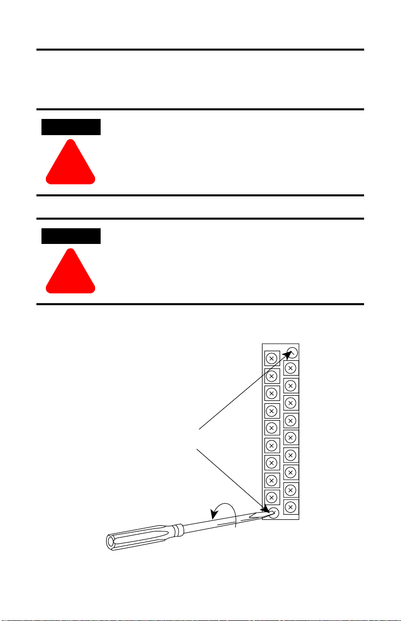
1. Remove the RTB from the input module. To avoid cracking the RTB,
alternate between the two release screws when loosening.
Terminal Block Release Screws
Maximum Torque = 0.7 to 0.9 Nm (6 to 8 in-lb)
Publication 1746-IN024A-EN-P - October 2001
Page 3

SLC 500 Input Simulator 3
2. Mount the 1746-SIM on the input module. Align the Input Simulator release
screws with the mating connector on the module and press the Input
Simulator firmly onto the connector contacts. To avoid damage to the Input
Simulator connector/RTB, alternate between the two screws when
tightening.
Secure the Input Simulator to the input module with the
captive screws. Alternate tighening to avoid damage.
11/64 inch dia.
15
through hole
24V dc
Input Power
Connector
USER POWER SUPPLY CONNECTION
128mA @ 24V dc max (All 16 inputs on)
Sourcing Input Module: A = DC COM B = +24V dc
Sinking Input Module: A = +24V dc B = DC COM
0
1
2
3
4
5
6
7
10
8
9
10
11
12
14
3. Connect the 24V dc power supply to the terminals labeled A and B as stated
in the instructions on the Input Simulator. In most instances, the 24V dc user
power available in the SLC 500 power supply can be used. The Input
Simulator A/B terminal block is removable for convenience in making this
connection.
Publication 1746-IN024A-EN-P - October 2001
Page 4

For More Information
For Refer to this Document Pub. No.
A more detailed description on how to
install and use your modular SLC 500
system.
Detailed information on installing and
wiring discrete I/O modules in an SLC
system.
If you would like a manual, you can:
• download a free electronic version from the internet:
www.theautomationbookstore.com
• purchase a printed manual by:
– contacting your local distributor or Rockwell Automation representative
– visiting www.theautomationbookstore.com and placing your order
– calling 1.800.963.9548 (USA/Canada)
or 001.330.725.1574 (Outside USA/Canada)
SLC 500 Modular Hardware
Style Installation and
Operation Manual
Discrete I/O Modules
Installation Instructions
1747-UM011C-EN-P
1746-IN005A-US-P
SLC 500 is a trademark of Rockwell Automation.
Publication 1746-IN024A-EN-P - October 2001 PN 40071-142-01(1)
Copyright © 2001 Rockwell Automation. All rights reserved. Printed in the U.S.A.
 Loading...