

Page 1
Installation Instructions
SLC 500™ 32-Point I/O Module Connector Kit
(Catalog Number 1746-N3)
Overview
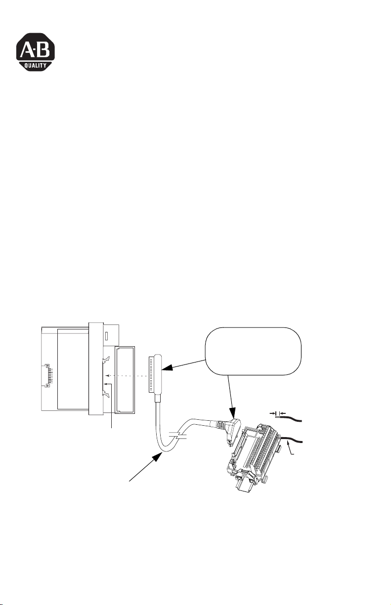
The 1746-N3 Connector Kit is used to terminate a cable which connects field I/O
devices to SLC 500 32-point I/O modules. The kit contains a keyed 40-pin socket
header with 45 socket crimp type contacts.
The N3 connector is compatible with 32-point I/O modules, catalog numbers
1746-IB32, -IV32, -OB32, -OB32E -OV32 and Allen-Bradley 1492-IFM40 terminal
blocks (see illustration). When the 1746-N3 is used to terminate the I/O cable at the
1492-IFM40 end, it should be wired in a straight-through manner (i.e. pin 1 to pin 1,
pin 2 to pin 2, etc.). For additional instructions, refer to the wiring instructions
provided with your 32-point I/O module.
Use 24 AWG wire with the 1746-N3. Maximum wire length to the user terminal
block is 10 meters for inputs and 3 meters for outputs with 7-strand, 24 AWG wire.
1746-N3 Connector
Keyed to prevent improper
insertion.
(one connector is provided with
each 32-point I/O module)
0.32 in. (8 mm) REF.
32-Point I/O Module
Male MIL-C-83503 Header
User Assembled Cable
(1) To maintain group isolation provided by 32-point I/O modules, use a 1492 terminal block that provides group isolation.
Consult 1492 documentation or your Allen-Bradley Sales Office for additional information.
(2) Maximum user cable length is dependent on how much voltage drop (current x (ohms/ft.) x (feet)) the user’s system can
tolerate. The user’s system should take into account the minimum turn-on voltage required by external loads connected to
the 32-point output modules and all of the voltage drops associated with wiring to and from the load, terminal blocks,
power sources and the module itself.
1492-IFM40xx DIN rail
mountable terminal block
24 to 12 AWG
(0.2 to 4mm
2
)
(1)
Publication 1746-IN025A-EN-P - June 2002
Page 2
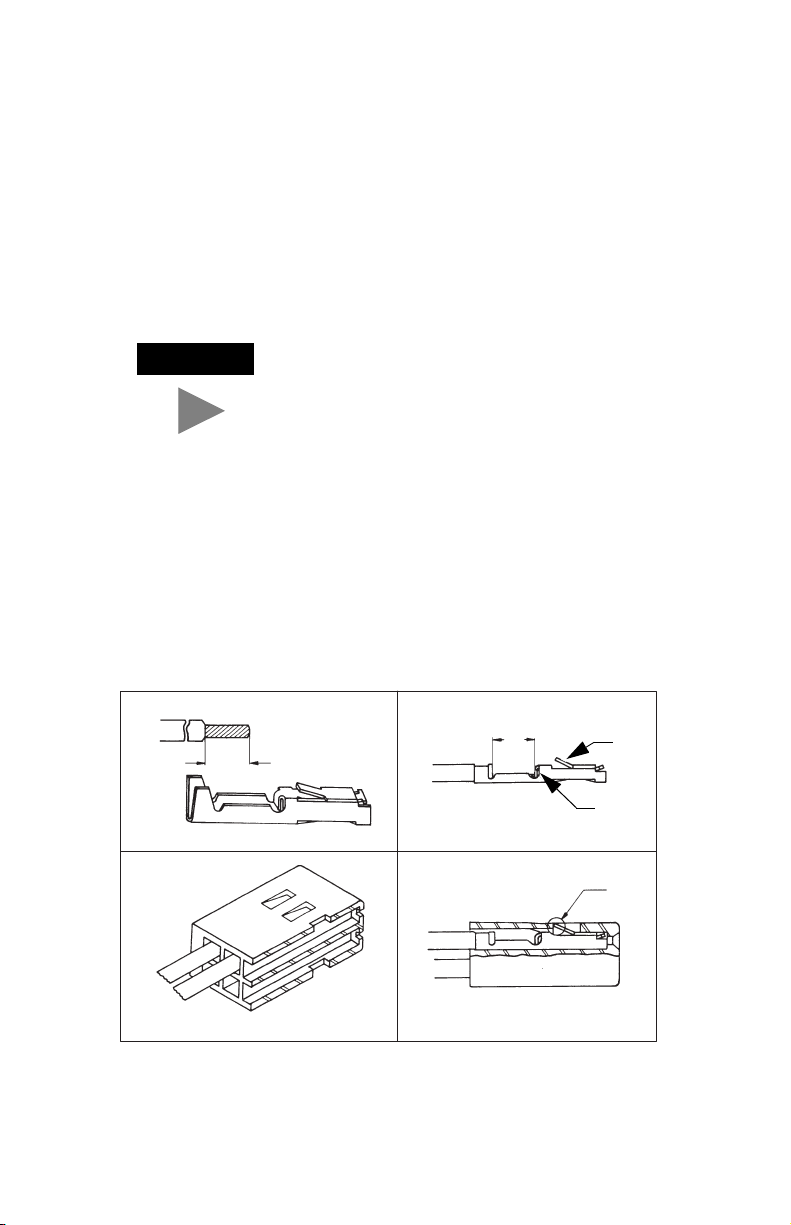
Assembly Procedure for Crimp Contacts
The following details the assembly procedure for the crimp type contacts.
1. Strip the wire insulation as shown in Figure 1.
2. Insert the wire up to the wire stop as shown in Figure 2.
3. Crimp with DDK crimp tool 357J-5538. Equivalent Amp part numbers are:
pin - 87666-2, connector - 102387-9, and crimp tool - 90418-1.
TIP
Pins and connectors from different manufacturers
cannot be assembled together. For example, Amp pins
cannot be used with a DDK connector.
If a crimp tool is not available, used the following crimping procedure:
a. Crimp the wire barrel around the wire using a small needle nose pliers.
b. Crimp the insulation barrel around the wire insulation using a small
needle nose pliers.
c. Solder wire and wire barrel together.
4. After completing above assembly, insert the cable into the socket housing as
shown in Figures 3 and 4. Check to make sure that the tang, shown as “A” in
Figure 4, is properly latched by gently pulling on the wire.
4 mm
4 mm
4 mm
(5/32 in)
(5/32 in)
Figure 1
4 mm
(5/32 in)
(5/32 in)
Figure 2
Tang
Wire Stop
A
A
Figure 3
Figure 4
Publication 1746-IN025A-EN-P - June 2002 PN 40071-147-01(1)
Supersedes Publication 40063-139-01(A ) - August 1992 © 2002 Rockwell International Corpor ation. Printed in the U.S.A.
 Loading...